EP2469635A1 - Method of making a solid oxide fuel cell stack - Google Patents
Method of making a solid oxide fuel cell stack Download PDFInfo
- Publication number
- EP2469635A1 EP2469635A1 EP11192014A EP11192014A EP2469635A1 EP 2469635 A1 EP2469635 A1 EP 2469635A1 EP 11192014 A EP11192014 A EP 11192014A EP 11192014 A EP11192014 A EP 11192014A EP 2469635 A1 EP2469635 A1 EP 2469635A1
- Authority
- EP
- European Patent Office
- Prior art keywords
- fuel cell
- separator plate
- conductive
- making
- cobalt
- Prior art date
- Legal status (The legal status is an assumption and is not a legal conclusion. Google has not performed a legal analysis and makes no representation as to the accuracy of the status listed.)
- Withdrawn
Links
- 239000000446 fuel Substances 0.000 title claims abstract description 80
- 238000004519 manufacturing process Methods 0.000 title claims abstract description 25
- 239000007787 solid Substances 0.000 title claims abstract description 11
- 238000000576 coating method Methods 0.000 claims abstract description 68
- 238000007789 sealing Methods 0.000 claims abstract description 46
- 239000011248 coating agent Substances 0.000 claims abstract description 42
- 239000011521 glass Substances 0.000 claims abstract description 38
- 230000002708 enhancing effect Effects 0.000 claims abstract description 27
- 239000000565 sealant Substances 0.000 claims abstract description 25
- 238000000034 method Methods 0.000 claims abstract description 17
- 238000010344 co-firing Methods 0.000 claims abstract description 13
- 230000000295 complement effect Effects 0.000 claims abstract description 6
- 238000005304 joining Methods 0.000 claims abstract 3
- 239000010941 cobalt Substances 0.000 claims description 22
- 229910017052 cobalt Inorganic materials 0.000 claims description 22
- GUTLYIVDDKVIGB-UHFFFAOYSA-N cobalt atom Chemical compound [Co] GUTLYIVDDKVIGB-UHFFFAOYSA-N 0.000 claims description 22
- 229910052782 aluminium Inorganic materials 0.000 claims description 10
- XAGFODPZIPBFFR-UHFFFAOYSA-N aluminium Chemical compound [Al] XAGFODPZIPBFFR-UHFFFAOYSA-N 0.000 claims description 10
- 239000011651 chromium Substances 0.000 claims description 9
- VYZAMTAEIAYCRO-UHFFFAOYSA-N Chromium Chemical compound [Cr] VYZAMTAEIAYCRO-UHFFFAOYSA-N 0.000 claims description 8
- 229910052804 chromium Inorganic materials 0.000 claims description 8
- 229910000428 cobalt oxide Inorganic materials 0.000 claims description 7
- IVMYJDGYRUAWML-UHFFFAOYSA-N cobalt(ii) oxide Chemical compound [Co]=O IVMYJDGYRUAWML-UHFFFAOYSA-N 0.000 claims description 7
- IJGRMHOSHXDMSA-UHFFFAOYSA-N Atomic nitrogen Chemical compound N#N IJGRMHOSHXDMSA-UHFFFAOYSA-N 0.000 claims description 6
- 239000001257 hydrogen Substances 0.000 claims description 6
- 229910052739 hydrogen Inorganic materials 0.000 claims description 6
- 239000000203 mixture Substances 0.000 claims description 6
- 239000001301 oxygen Substances 0.000 claims description 5
- 229910052760 oxygen Inorganic materials 0.000 claims description 5
- QVGXLLKOCUKJST-UHFFFAOYSA-N atomic oxygen Chemical compound [O] QVGXLLKOCUKJST-UHFFFAOYSA-N 0.000 claims description 4
- 238000007772 electroless plating Methods 0.000 claims description 4
- 238000009713 electroplating Methods 0.000 claims description 4
- 229910045601 alloy Inorganic materials 0.000 claims description 3
- 239000000956 alloy Substances 0.000 claims description 3
- 229910052757 nitrogen Inorganic materials 0.000 claims description 3
- 229910001220 stainless steel Inorganic materials 0.000 claims description 3
- 229910001256 stainless steel alloy Inorganic materials 0.000 claims description 3
- 238000005229 chemical vapour deposition Methods 0.000 claims description 2
- 238000000151 deposition Methods 0.000 claims description 2
- 230000008021 deposition Effects 0.000 claims description 2
- 238000010438 heat treatment Methods 0.000 claims description 2
- 239000002002 slurry Substances 0.000 claims description 2
- 238000004891 communication Methods 0.000 claims 2
- 125000004435 hydrogen atom Chemical class [H]* 0.000 claims 2
- 238000000429 assembly Methods 0.000 abstract description 2
- 230000000712 assembly Effects 0.000 abstract description 2
- 229910052751 metal Inorganic materials 0.000 description 8
- 239000002184 metal Substances 0.000 description 8
- 239000003792 electrolyte Substances 0.000 description 6
- WGLPBDUCMAPZCE-UHFFFAOYSA-N Trioxochromium Chemical compound O=[Cr](=O)=O WGLPBDUCMAPZCE-UHFFFAOYSA-N 0.000 description 5
- 239000000758 substrate Substances 0.000 description 5
- 239000000463 material Substances 0.000 description 4
- UFHFLCQGNIYNRP-UHFFFAOYSA-N Hydrogen Chemical compound [H][H] UFHFLCQGNIYNRP-UHFFFAOYSA-N 0.000 description 3
- 229910000423 chromium oxide Inorganic materials 0.000 description 3
- 230000008020 evaporation Effects 0.000 description 3
- 238000001704 evaporation Methods 0.000 description 3
- XEEYBQQBJWHFJM-UHFFFAOYSA-N Iron Chemical compound [Fe] XEEYBQQBJWHFJM-UHFFFAOYSA-N 0.000 description 2
- PXHVJJICTQNCMI-UHFFFAOYSA-N Nickel Chemical compound [Ni] PXHVJJICTQNCMI-UHFFFAOYSA-N 0.000 description 2
- 239000011230 binding agent Substances 0.000 description 2
- AYTAKQFHWFYBMA-UHFFFAOYSA-N chromium dioxide Chemical compound O=[Cr]=O AYTAKQFHWFYBMA-UHFFFAOYSA-N 0.000 description 2
- GAMDZJFZMJECOS-UHFFFAOYSA-N chromium(6+);oxygen(2-) Chemical compound [O-2].[O-2].[O-2].[Cr+6] GAMDZJFZMJECOS-UHFFFAOYSA-N 0.000 description 2
- 238000005260 corrosion Methods 0.000 description 2
- 230000007797 corrosion Effects 0.000 description 2
- 230000005611 electricity Effects 0.000 description 2
- 239000007789 gas Substances 0.000 description 2
- 230000003647 oxidation Effects 0.000 description 2
- 238000007254 oxidation reaction Methods 0.000 description 2
- 125000006850 spacer group Chemical group 0.000 description 2
- 229910052596 spinel Inorganic materials 0.000 description 2
- 239000011029 spinel Substances 0.000 description 2
- 229910052720 vanadium Inorganic materials 0.000 description 2
- GPPXJZIENCGNKB-UHFFFAOYSA-N vanadium Chemical compound [V]#[V] GPPXJZIENCGNKB-UHFFFAOYSA-N 0.000 description 2
- RYGMFSIKBFXOCR-UHFFFAOYSA-N Copper Chemical compound [Cu] RYGMFSIKBFXOCR-UHFFFAOYSA-N 0.000 description 1
- FYYHWMGAXLPEAU-UHFFFAOYSA-N Magnesium Chemical compound [Mg] FYYHWMGAXLPEAU-UHFFFAOYSA-N 0.000 description 1
- -1 Oxygen ions Chemical class 0.000 description 1
- PNEYBMLMFCGWSK-UHFFFAOYSA-N aluminium oxide Inorganic materials [O-2].[O-2].[O-2].[Al+3].[Al+3] PNEYBMLMFCGWSK-UHFFFAOYSA-N 0.000 description 1
- 230000015556 catabolic process Effects 0.000 description 1
- 238000006555 catalytic reaction Methods 0.000 description 1
- 229940117975 chromium trioxide Drugs 0.000 description 1
- MOEHVXSVUJUROX-UHFFFAOYSA-M chromium(3+);oxygen(2-);hydroxide Chemical compound [OH-].[O-2].[Cr+3] MOEHVXSVUJUROX-UHFFFAOYSA-M 0.000 description 1
- JOPOVCBBYLSVDA-UHFFFAOYSA-N chromium(6+) Chemical class [Cr+6] JOPOVCBBYLSVDA-UHFFFAOYSA-N 0.000 description 1
- 239000004020 conductor Substances 0.000 description 1
- 229910052802 copper Inorganic materials 0.000 description 1
- 239000010949 copper Substances 0.000 description 1
- 238000006731 degradation reaction Methods 0.000 description 1
- 238000010304 firing Methods 0.000 description 1
- 239000002241 glass-ceramic Substances 0.000 description 1
- 150000002431 hydrogen Chemical class 0.000 description 1
- 150000002500 ions Chemical class 0.000 description 1
- 229910052742 iron Inorganic materials 0.000 description 1
- 229910052749 magnesium Inorganic materials 0.000 description 1
- 239000011777 magnesium Substances 0.000 description 1
- WPBNNNQJVZRUHP-UHFFFAOYSA-L manganese(2+);methyl n-[[2-(methoxycarbonylcarbamothioylamino)phenyl]carbamothioyl]carbamate;n-[2-(sulfidocarbothioylamino)ethyl]carbamodithioate Chemical compound [Mn+2].[S-]C(=S)NCCNC([S-])=S.COC(=O)NC(=S)NC1=CC=CC=C1NC(=S)NC(=O)OC WPBNNNQJVZRUHP-UHFFFAOYSA-L 0.000 description 1
- 239000011159 matrix material Substances 0.000 description 1
- 229910052759 nickel Inorganic materials 0.000 description 1
- 239000007800 oxidant agent Substances 0.000 description 1
- 230000001590 oxidative effect Effects 0.000 description 1
- TWNQGVIAIRXVLR-UHFFFAOYSA-N oxo(oxoalumanyloxy)alumane Chemical compound O=[Al]O[Al]=O TWNQGVIAIRXVLR-UHFFFAOYSA-N 0.000 description 1
- 238000005240 physical vapour deposition Methods 0.000 description 1
- 231100000572 poisoning Toxicity 0.000 description 1
- 230000000607 poisoning effect Effects 0.000 description 1
- 239000000843 powder Substances 0.000 description 1
- 239000000376 reactant Substances 0.000 description 1
- 239000000126 substance Substances 0.000 description 1
- 238000009834 vaporization Methods 0.000 description 1
- 230000008016 vaporization Effects 0.000 description 1
- XLYOFNOQVPJJNP-UHFFFAOYSA-N water Substances O XLYOFNOQVPJJNP-UHFFFAOYSA-N 0.000 description 1
Images

Classifications
-
- H—ELECTRICITY
- H01—ELECTRIC ELEMENTS
- H01M—PROCESSES OR MEANS, e.g. BATTERIES, FOR THE DIRECT CONVERSION OF CHEMICAL ENERGY INTO ELECTRICAL ENERGY
- H01M8/00—Fuel cells; Manufacture thereof
- H01M8/02—Details
- H01M8/0202—Collectors; Separators, e.g. bipolar separators; Interconnectors
- H01M8/0204—Non-porous and characterised by the material
- H01M8/0206—Metals or alloys
-
- H—ELECTRICITY
- H01—ELECTRIC ELEMENTS
- H01M—PROCESSES OR MEANS, e.g. BATTERIES, FOR THE DIRECT CONVERSION OF CHEMICAL ENERGY INTO ELECTRICAL ENERGY
- H01M8/00—Fuel cells; Manufacture thereof
- H01M8/02—Details
- H01M8/0202—Collectors; Separators, e.g. bipolar separators; Interconnectors
- H01M8/0204—Non-porous and characterised by the material
- H01M8/0223—Composites
- H01M8/0228—Composites in the form of layered or coated products
-
- H—ELECTRICITY
- H01—ELECTRIC ELEMENTS
- H01M—PROCESSES OR MEANS, e.g. BATTERIES, FOR THE DIRECT CONVERSION OF CHEMICAL ENERGY INTO ELECTRICAL ENERGY
- H01M8/00—Fuel cells; Manufacture thereof
- H01M8/02—Details
- H01M8/0271—Sealing or supporting means around electrodes, matrices or membranes
- H01M8/028—Sealing means characterised by their material
- H01M8/0282—Inorganic material
-
- H—ELECTRICITY
- H01—ELECTRIC ELEMENTS
- H01M—PROCESSES OR MEANS, e.g. BATTERIES, FOR THE DIRECT CONVERSION OF CHEMICAL ENERGY INTO ELECTRICAL ENERGY
- H01M8/00—Fuel cells; Manufacture thereof
- H01M8/02—Details
- H01M8/0271—Sealing or supporting means around electrodes, matrices or membranes
- H01M8/0286—Processes for forming seals
-
- H—ELECTRICITY
- H01—ELECTRIC ELEMENTS
- H01M—PROCESSES OR MEANS, e.g. BATTERIES, FOR THE DIRECT CONVERSION OF CHEMICAL ENERGY INTO ELECTRICAL ENERGY
- H01M8/00—Fuel cells; Manufacture thereof
- H01M8/10—Fuel cells with solid electrolytes
- H01M8/12—Fuel cells with solid electrolytes operating at high temperature, e.g. with stabilised ZrO2 electrolyte
- H01M8/124—Fuel cells with solid electrolytes operating at high temperature, e.g. with stabilised ZrO2 electrolyte characterised by the process of manufacturing or by the material of the electrolyte
-
- H—ELECTRICITY
- H01—ELECTRIC ELEMENTS
- H01M—PROCESSES OR MEANS, e.g. BATTERIES, FOR THE DIRECT CONVERSION OF CHEMICAL ENERGY INTO ELECTRICAL ENERGY
- H01M8/00—Fuel cells; Manufacture thereof
- H01M8/10—Fuel cells with solid electrolytes
- H01M8/12—Fuel cells with solid electrolytes operating at high temperature, e.g. with stabilised ZrO2 electrolyte
- H01M2008/1293—Fuel cells with solid oxide electrolytes
-
- Y—GENERAL TAGGING OF NEW TECHNOLOGICAL DEVELOPMENTS; GENERAL TAGGING OF CROSS-SECTIONAL TECHNOLOGIES SPANNING OVER SEVERAL SECTIONS OF THE IPC; TECHNICAL SUBJECTS COVERED BY FORMER USPC CROSS-REFERENCE ART COLLECTIONS [XRACs] AND DIGESTS
- Y02—TECHNOLOGIES OR APPLICATIONS FOR MITIGATION OR ADAPTATION AGAINST CLIMATE CHANGE
- Y02E—REDUCTION OF GREENHOUSE GAS [GHG] EMISSIONS, RELATED TO ENERGY GENERATION, TRANSMISSION OR DISTRIBUTION
- Y02E60/00—Enabling technologies; Technologies with a potential or indirect contribution to GHG emissions mitigation
- Y02E60/30—Hydrogen technology
- Y02E60/50—Fuel cells
-
- Y—GENERAL TAGGING OF NEW TECHNOLOGICAL DEVELOPMENTS; GENERAL TAGGING OF CROSS-SECTIONAL TECHNOLOGIES SPANNING OVER SEVERAL SECTIONS OF THE IPC; TECHNICAL SUBJECTS COVERED BY FORMER USPC CROSS-REFERENCE ART COLLECTIONS [XRACs] AND DIGESTS
- Y02—TECHNOLOGIES OR APPLICATIONS FOR MITIGATION OR ADAPTATION AGAINST CLIMATE CHANGE
- Y02P—CLIMATE CHANGE MITIGATION TECHNOLOGIES IN THE PRODUCTION OR PROCESSING OF GOODS
- Y02P70/00—Climate change mitigation technologies in the production process for final industrial or consumer products
- Y02P70/50—Manufacturing or production processes characterised by the final manufactured product
Definitions
- the present disclosure is related to a method of making a Solid Oxide Fuel Cell (SOFC) stack; more particularly, a method of coating and assembling a SOFC stack.
- SOFC Solid Oxide Fuel Cell
- Fuel cells are used to produce electricity when supplied with fuels containing hydrogen and an oxidant such as air.
- a typical fuel cell includes an ion conductive electrolyte layer sandwiched between a cathode layer and an anode layer.
- SOFC solid oxide fuel cells
- SOFC are regarded as highly efficient electrical power generator that produces high power density with fuel flexibility.
- a fuel containing hydrogen is passed over the surface of the anode layer opposite that of the cathode layer.
- Oxygen ions from the air migrate from the cathode layer through the dense electrolyte to the anode layer in which it reacts with the hydrogen and CO in the fuel, forming water and CO 2 ; thereby, creating an electrical potential between the anode layer and the cathode layer of about 1 volt.
- Each individual SOFC is mounted within a metal frame, referred to in the art as a retainer, to form a cell-retainer assembly.
- the individual cell-retainer assembly is then joined to a metal separator plate, also known as an interconnector plate, to form a fuel cell cassette.
- the fuel cell cassettes are stacked in series with a seal applied about the perimeter of adjacent fuel cell cassettes to form a SOFC stack.
- the separator plate or interconnector plate, includes an anode facing surface, which is oriented toward the anode layer of the SOFC in the cell-retainer assembly to which it is attached, and an opposite cathode facing surface, which is oriented toward the cathode layer of the SOFC of the adjacent fuel cell cassette.
- the seal is applied between the sealing surfaces of the cathode facing surface of the separator plate and the sealing surfaces of the cell-retainer assembly of the adjacent cassette.
- Portions of the anode facing surface and cathode facing surface of the separator plate are conductive surfaces.
- conductive coatings are provided on the conductive surfaces for enhanced electron conduction and to prevent chromium poisoning of the cathode layer of the SOFC of the adjacent cassette.
- a seal enhancing coating is provided along the sealing surfaces of the separator plate to enhance the adhesion and strength of the seal.
- the separator plate is heat treated at a first temperature to sinter the conductive coatings onto the separator plate. Then, the seal enhancing coating is applied along the sealing surfaces of the separator plate. The separator plate is heat treated at a second temperature to sinter the seal enhancing coating onto the separator plate. It is known in the art to apply the seal enhancing coating first and then the conducting coating or vise-versa; however, each coating process requires heat treating at different temperatures, time periods, and atmosphere conditions. After the conductive and seal coatings are applied onto the separator plate and the separator plate is assembled into a cassette. A plurality of fuel cell cassettes is assembled into a SOFC stack with sealants, typically that of a glass matrix, therebetween fuel cell cassettes. The SOFC stack is then heat treated again at a third temperature, time period, and atmosphere to sinter the stack into one unit and to devitrify the sealant into a bonded glass joint.
- a method in accordance with the present invention is defined by the features of claim 1.
- An embodiment of the present invention provides a method of making a solid oxide fuel cell (SOFC) stack that includes the steps of providing a separator plate having an anode conductive surface, a cathode conductive surface opposite of the anode conductive surface, and a sealing surface.
- a conductive coating is applied onto at least one of the conductive surfaces and a seal enhancing coating is applied onto the sealing surface.
- the coatings are simultaneously co-fired such that the conductive coating and seal enhancing coating are bonded into at least one of conductive surfaces and the sealing surface, respectively.
- the coated separator plate is then joined to cell-retainer assembly to form a first fuel cell cassette.
- a second fuel cell cassette having a complementary sealing surface of the separator plate is provided.
- the first fuel cell cassette is assembled with the second fuel cell cassette with a glass sealant between the respective sealing surfaces to form a SOFC stack.
- the SOFC is then heat treated at a sufficiently high temperature and time to form a glass seal gasket therebetween the fuel cell cassettes.
- Another embodiment of the invention provides a method of making a solid oxide fuel cell (SOFC) stack that includes the steps of providing a first cell-retainer assembly, providing a first separator plate having an anode conductive surface, a cathode conductive surface opposite of the anode conductive surface, and a sealing surface.
- a seal enhancing coating is applied onto the sealing surface of the first separator plate and a conductive coating is applied onto at least one of the conductive surface of first separator plate.
- the separator plate is joined onto the first cell-retainer assembly, thereby forming a first fuel cell cassette.
- a second fuel cell cassette having a sealing surface complementary with the sealing surface of the separator plate is provided, wherein the second fuel cell cassette is formed by the same method of making the first fuel cell cassette.
- a glass sealant is applied onto the sealing surface of first fuel cell cassette.
- the first fuel cell cassette is assembled onto the second fuel cell cassette with the glass sealant therebetween, thereby forming a SOFC stack.
- the SOFC stack is then heat treated to simultaneously co-fire the seal enhancing coating, conductive coating, and glass sealant such that the seal enhancing and conductive coatings are bonded onto the sealing surface and the at least one of conductive surfaces, respectively, and the glass sealant forms a glass gasket.
- the improved method of coating and assembling a SOFC stack provides the advantages of a robust seal between the fuel cell cassettes as well as improved adherence of conductive and sealing coatings.
- the improve method reduces the complexity of manufacturing and lowers the costs of manufacturing a SOFC stack.
- FIG. 1 is a schematic drawing of a solid oxide fuel cell (SOFC) mounted in a retainer frame.
- SOFC solid oxide fuel cell
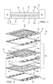
- FIG. 2 is an exploded isometric drawing of a portion of a SOFC stack employing a plurality of single-cell cassettes.
- Fig. 3 is an isometric drawing of the underside of the separator plate shown in Fig. 2 .
- FIG. 1 through 3 Shown in Figs. 1 through 3 , wherein like numerals indicate corresponding parts throughout the figures, is an exemplary solid oxide fuel cell (SOFC) stack 26 and components of the SOFC stack 26.
- SOFC solid oxide fuel cell
- FIG. 1 Shown in Fig. 1 is a schematic drawing of a cross-section of a fuel cell 10 mounted in a cell retainer 22.
- the fuel cell 10 includes an electrolyte layer 14, a cathode layer 12 bonded onto one side of the electrolyte layer 14, and an anode layer 16 bonded to the opposite side of the electrolyte layer 14.
- the cathode layer 12 includes a cathode layer surface 34 and the anode layer 16 includes an anode layer surface 31.
- the cathode layer surface 34 and anode layer surface 31 are oriented away from the electrolyte layer 14 in a direction opposite of each other.
- Each individual fuel cell 10 is mounted within a cell retainer 22 formed of a metal substrate.
- the cell retainer 22 defines a central opening or picture frame window 23.
- the fuel cell 10 is positioned in the picture frame window 23 and joined to the cell retainer 22 to form a cell-retainer assembly 24.
- the cell-retainer assembly 24 includes an anode side 24a and a cathode side 24b that correspond to the anode layer surface 31 and cathode layer surface 34 of the fuel cell 10, respectively.
- an intermediate process joins together each cell-retainer assembly 24 with a separator plate 28, an anode interconnect 30, and inlet and outlet anode spacers 29a, 29b to form an intermediate structure known as a fuel cell cassette 32.
- the separator plate 28 is typically stamped from a thin sheet of metal and formed to provide, when mated to the cell retainer 22 and joined to the anode spacers 29a, 29b, a flow space for the anode gas.
- the separator plate 28 is formed from a ferritic stainless steel alloy containing chromium (Cr) for low cost and corrosion protection.
- the anode interconnect 30 is positioned between the separator plate 28 and the anode layer surface 31 of the fuel cell 10 within the fuel cell cassette 32.
- a typical anode interconnect 30 is formed of a woven wire mesh of uniform thickness and is solid in the direction perpendicular to the anode layer surface 31 in a multitude of points.
- the anode interconnect 30 may also be stamped sheet metal with flow features and contacts such as flattened nails and ribs.
- a cathode interconnect 35 installed against the cathode layer surface 34 provides a cathode air flow space.
- the cathode interconnect 35 may also be of a woven wire mesh of uniform thickness and solid in the direction perpendicular to the cathode layer surface 34 in a multitude of points, as well as stamped sheet metal with flow features and contact features.
- FIG. 3 is an isometric drawing of the underside of the separator plate 28 shown in Fig. 2 .
- the separator plate 28 serves as a separator for air and fuel flow, as well as a conductor of current, between adjacent fuel cell cassettes 32 of the SOFC stack 26.
- the separator plate 28 includes an anode conductive surface 28a, which is oriented toward the anode side 24a of the cell-retainer assembly 24, to which it is attached, and an opposite cathode conductive surface 28b, which is oriented toward the cathode side 24b of the cell-retainer assembly 24 of the adjacent fuel cell cassette 32.
- the anode conductive surface 28a of the separator plate 28 is in electrical contact with the anode interconnect 30 of the immediate fuel cell cassette 32 and the cathode conductive surface 28b is in electrical contact with the cathode interconnect 35 of the adjacent fuel cell cassette 32.
- the separator plate 28 needs to retain its low electrical resistivity throughout the operating lifetime of the fuel cell 10 as well as high-temperature corrosion resistance.
- the desired characteristics for separator plate 28 can be satisfied by the use of chromium-oxide-forming high temperature materials. This group of materials formed at the typical SOFC operating temperatures includes a layer of chromium oxide that protects the material from rapid degradation by oxidation.
- the chromium oxide layer formed on the cathode conductive surface 28b of the separator plate 28 reacts with the oxygen in the air stream and H 2 O to form chromium trioxide (CrO 3 ) and/or chromium oxide hydroxide (CrO 2 (OH) 2 , CrO(OH) 4 ).
- CrO 3 chromium trioxide
- CrO 2 (OH) 2 , CrO(OH) 4 chromium oxide hydroxide
- These Cr(VI) compounds have relatively high vapor pressures at these elevated temperatures and react with the cathode layer 12 of the fuel cell 10 in the adjacent fuel cell cassette 32 to limit the catalytic reaction of the oxygen, thereby reducing the power density and efficiency of the SOFC stack 26 in producing electricity.
- cobalt, oxides of cobalt, and mixtures thereof have been used to coat the conductive surfaces of the separator plate 28 to reduce the chromium evaporation.
- Spinel coatings have also been used to suppress the chromium evaporation.
- a spinel coating encompassing an element from the group of manganese, magnesium, and vanadium and a further element from the group of cobalt, nickel, iron, copper, and vanadium, which when arranged on a chromium oxide forming substrate, prevents a vaporization of chromium from the substrate to temperatures of 1000 °C.
- a glass sealant 42 is disposed on the sealing surfaces 39 of adjacent fuel cell cassettes 32.
- a sealing surface 39 is located about the perimeter of the separator plate 28 on the same side as the cathode conductive surface 28b.
- the glass sealant 42 is heat treated to devitrify the glass to form a bonded glass seal joint to provide a gas-tight seal to separate and contain the reactant gases and electrically isolate adjacent separator plates 28.
- the corresponding sealing surfaces of the separator plate 28 and adjacent fuel cell cassette 32 may be coated with aluminum, aluminum oxide, or mixtures thereof.
- the glass sealant 42 may be of glass-ceramic or glass seal in powder or paste form and the glass sealant 42 is applied about the sealing surfaces of the separator plate of the cassette or about the sealing surfaces 39 of the cathode side 24b of the cell-retainer assembly 24 of the adjacent cassette. It is desirable for the resulting glass sealant 42 to have a coefficient of thermal expansion that is comparable with components of the SOFC stack 26, a suitable viscosity to fill the seal gaps between fuel cell 10 and separator plate 28 and sustain at the sealing surfaces of the SOFC stack 26 at working temperature while maintaining good thermal and chemical stability.
- An improved method of coating and assembly a SOFC stack includes applying a seal enhancing coating onto the sealing surfaces 39 of the separator plate 28 and applying a conductive coating onto the conductive surfaces 28a, 28b of the separator plate 28. It is preferable that the coating be applied by electroplating, electroless plating, and physical vapor deposition. It was found that these coating processes provide a desirable uniform coating of material having a low level of porosity. The coatings may also be applied by chemical vapor deposition or slurry deposition. After the application of the seal enhancing and conductive coatings, the separator plate 28 is heated treated in a reducing atmosphere such that the seal enhancing and conductive coatings are bonded onto their respective surfaces on the separator plate 28. In contrast to traditionally applying and co-firing the coatings separately, the improved method applies both coatings and then simultaneously co-firing the separator plate 28 to bond the coatings.
- a cobalt or cobalt oxide coating is used to coat the conductive surfaces 28a, 28b
- the coated separator plate 28 is then heat treated in a reducing atmosphere, which is selected from a group of atmospheres consisting of hydrogen, nitrogen (low partial oxygen), and vacuum at an elevated temperature and time such that the cobalt diffuses into the separator plate 28 forming a cobalt oxide layer near the conductive surface, a metallic cobalt layer beneath the cobalt oxide layer, and a cobalt rich stainless steel alloy beneath the metallic cobalt layer.
- a similar coating structure is also derived with the aluminum coated sealing surfaces where the aluminum diffuses into the metal substrate and a gradient of aluminum in the metal substrate and alumina in the surface is obtained which is desirable for glass seal bonding. It is desirable for the step of co-firing of the separator plate 28 at 800°C - 1000 °C for a time period for at least 15 minutes.
- the separator plate 28 is then assembled onto the cell-retainer assembly 24 to form a fuel cell cassette 32 as disclosed above.
- a plurality of fuel cell cassettes is assembled in a SOFC stack 26, with the glass sealant 42 applied between each of the fuel cell cassettes 32.
- the SOFC stack is heat treated a second time at 850°C - 1050 °C to devitrify the glass sealant 42 into a bonded glass joint and to sinter the stack into one complete unit.
- the seal enhancing and conductive coatings may be applied to a plurality of separator plates 28.
- the separator plates 28 are then assembled onto a plurality of complementary cell-retainer assemblies 24 to form a plurality of fuel cell cassettes 32.
- the fuel cell cassettes 32 are in turn assembled into a SOFC stack 26 with a glass sealant 42 applied between the sealing surfaces of each cassette 32.
- the glass sealant 42 may be applied as a glass paste or glass tape containing binders.
- the entire SOFC stack 26 is then co-fired within a reducing atmosphere, after the initial binders are burnt out, at between 850 °C to 1050 °C to concurrently bond the sealing and conductive coatings to their respective surfaces on the separator plate and to form a glass seal joint therebetween each cassette.
- the improved method of coating and assembling a SOFC stack provides the advantages of a robust seal between the fuel cell cassettes 32 as well as improved adherence of conductive and sealing coatings.
- the reduced number of high temperature processes results in reduced oxidation in uncoated surfaces of the SOFC stack components, thereby improving the robustness of the overall SOFC stack.
- the improve method is conducive to high volume manufacturability by reducing the number of high temperature firing steps required, thereby reducing the complexity of manufacturing and lowering cost.
Landscapes
- Chemical & Material Sciences (AREA)
- Engineering & Computer Science (AREA)
- Manufacturing & Machinery (AREA)
- Life Sciences & Earth Sciences (AREA)
- Sustainable Development (AREA)
- Sustainable Energy (AREA)
- Chemical Kinetics & Catalysis (AREA)
- Electrochemistry (AREA)
- General Chemical & Material Sciences (AREA)
- Inorganic Chemistry (AREA)
- Composite Materials (AREA)
- Fuel Cell (AREA)
Abstract
A method of making a solid oxide fuel cell (SOFC) stack that includes the steps of applying a seal enhancing coating and a conductive coating onto respective surfaces of a separator plate and simultaneously co-firing the coatings in a reducing atmosphere. The method may also include, prior to the step of co-firing, the step of assembling a plurality of separator plates with complementary cell-retainer assemblies to form a plurality of fuel cell cassettes. The fuel cell cassettes are then stacked with a glass sealant applied between the fuel cell cassettes to form a SOFC stack. The entire SOFC stack is then co-fired in a reducing atmosphere such that the seal enhancing and conductive coatings are bonded into the respective surfaces and the glass sealant devitrify to form a glass seal joining and sealing the cassettes of the SOFC stack.
Description
- The present disclosure is related to a method of making a Solid Oxide Fuel Cell (SOFC) stack; more particularly, a method of coating and assembling a SOFC stack.
- Fuel cells are used to produce electricity when supplied with fuels containing hydrogen and an oxidant such as air. A typical fuel cell includes an ion conductive electrolyte layer sandwiched between a cathode layer and an anode layer. There are several different types of fuel cells known in the art; amongst these are solid oxide fuel cells (SOFC). SOFC are regarded as highly efficient electrical power generator that produces high power density with fuel flexibility.
- In a typical SOFC, air is passed over the surface of the cathode layer and a fuel containing hydrogen is passed over the surface of the anode layer opposite that of the cathode layer. Oxygen ions from the air migrate from the cathode layer through the dense electrolyte to the anode layer in which it reacts with the hydrogen and CO in the fuel, forming water and CO2; thereby, creating an electrical potential between the anode layer and the cathode layer of about 1 volt.
- Each individual SOFC is mounted within a metal frame, referred to in the art as a retainer, to form a cell-retainer assembly. The individual cell-retainer assembly is then joined to a metal separator plate, also known as an interconnector plate, to form a fuel cell cassette. The fuel cell cassettes are stacked in series with a seal applied about the perimeter of adjacent fuel cell cassettes to form a SOFC stack.
- The separator plate, or interconnector plate, includes an anode facing surface, which is oriented toward the anode layer of the SOFC in the cell-retainer assembly to which it is attached, and an opposite cathode facing surface, which is oriented toward the cathode layer of the SOFC of the adjacent fuel cell cassette. The seal is applied between the sealing surfaces of the cathode facing surface of the separator plate and the sealing surfaces of the cell-retainer assembly of the adjacent cassette.
- Portions of the anode facing surface and cathode facing surface of the separator plate are conductive surfaces. Traditionally, before assembly of the separator plate to the cell-retainer assembly, conductive coatings are provided on the conductive surfaces for enhanced electron conduction and to prevent chromium poisoning of the cathode layer of the SOFC of the adjacent cassette. A seal enhancing coating is provided along the sealing surfaces of the separator plate to enhance the adhesion and strength of the seal.
- After the conductive coating is applied, the separator plate is heat treated at a first temperature to sinter the conductive coatings onto the separator plate. Then, the seal enhancing coating is applied along the sealing surfaces of the separator plate. The separator plate is heat treated at a second temperature to sinter the seal enhancing coating onto the separator plate. It is known in the art to apply the seal enhancing coating first and then the conducting coating or vise-versa; however, each coating process requires heat treating at different temperatures, time periods, and atmosphere conditions. After the conductive and seal coatings are applied onto the separator plate and the separator plate is assembled into a cassette. A plurality of fuel cell cassettes is assembled into a SOFC stack with sealants, typically that of a glass matrix, therebetween fuel cell cassettes. The SOFC stack is then heat treated again at a third temperature, time period, and atmosphere to sinter the stack into one unit and to devitrify the sealant into a bonded glass joint.
- This traditional process of coating and assembling a SOFC stack requires a multiple complex series of coating, heat treatment, and assembly operations for manufacturing a SOFC stack, which is labor intensive and costly. There is a need to have a method of coating and making of a SOFC stack that is simple and cost efficient.
- A method in accordance with the present invention is defined by the features of claim 1.
- An embodiment of the present invention provides a method of making a solid oxide fuel cell (SOFC) stack that includes the steps of providing a separator plate having an anode conductive surface, a cathode conductive surface opposite of the anode conductive surface, and a sealing surface. A conductive coating is applied onto at least one of the conductive surfaces and a seal enhancing coating is applied onto the sealing surface. The coatings are simultaneously co-fired such that the conductive coating and seal enhancing coating are bonded into at least one of conductive surfaces and the sealing surface, respectively.
- The coated separator plate is then joined to cell-retainer assembly to form a first fuel cell cassette. A second fuel cell cassette having a complementary sealing surface of the separator plate is provided. The first fuel cell cassette is assembled with the second fuel cell cassette with a glass sealant between the respective sealing surfaces to form a SOFC stack. The SOFC is then heat treated at a sufficiently high temperature and time to form a glass seal gasket therebetween the fuel cell cassettes.
- Another embodiment of the invention provides a method of making a solid oxide fuel cell (SOFC) stack that includes the steps of providing a first cell-retainer assembly, providing a first separator plate having an anode conductive surface, a cathode conductive surface opposite of the anode conductive surface, and a sealing surface. A seal enhancing coating is applied onto the sealing surface of the first separator plate and a conductive coating is applied onto at least one of the conductive surface of first separator plate. The separator plate is joined onto the first cell-retainer assembly, thereby forming a first fuel cell cassette. A second fuel cell cassette having a sealing surface complementary with the sealing surface of the separator plate is provided, wherein the second fuel cell cassette is formed by the same method of making the first fuel cell cassette. A glass sealant is applied onto the sealing surface of first fuel cell cassette. The first fuel cell cassette is assembled onto the second fuel cell cassette with the glass sealant therebetween, thereby forming a SOFC stack. The SOFC stack is then heat treated to simultaneously co-fire the seal enhancing coating, conductive coating, and glass sealant such that the seal enhancing and conductive coatings are bonded onto the sealing surface and the at least one of conductive surfaces, respectively, and the glass sealant forms a glass gasket.
- The improved method of coating and assembling a SOFC stack provides the advantages of a robust seal between the fuel cell cassettes as well as improved adherence of conductive and sealing coatings. The improve method reduces the complexity of manufacturing and lowers the costs of manufacturing a SOFC stack.
- Further features and advantages of the invention will appear more clearly on a reading of the following detailed description of an embodiment of the invention, which is given by way of non-limiting example only and with reference to the accompanying drawings.
- The present invention may best be understood from the following detailed description of the preferred embodiments illustrated in the drawings, wherein:
-
FIG. 1 is a schematic drawing of a solid oxide fuel cell (SOFC) mounted in a retainer frame. -
FIG. 2 is an exploded isometric drawing of a portion of a SOFC stack employing a plurality of single-cell cassettes. -
Fig. 3 is an isometric drawing of the underside of the separator plate shown inFig. 2 . - Shown in
Figs. 1 through 3 , wherein like numerals indicate corresponding parts throughout the figures, is an exemplary solid oxide fuel cell (SOFC)stack 26 and components of theSOFC stack 26. - Shown in
Fig. 1 is a schematic drawing of a cross-section of afuel cell 10 mounted in acell retainer 22. Thefuel cell 10 includes anelectrolyte layer 14, acathode layer 12 bonded onto one side of theelectrolyte layer 14, and ananode layer 16 bonded to the opposite side of theelectrolyte layer 14. Thecathode layer 12 includes acathode layer surface 34 and theanode layer 16 includes ananode layer surface 31. Thecathode layer surface 34 andanode layer surface 31 are oriented away from theelectrolyte layer 14 in a direction opposite of each other. - Each
individual fuel cell 10 is mounted within acell retainer 22 formed of a metal substrate. Thecell retainer 22 defines a central opening orpicture frame window 23. Thefuel cell 10 is positioned in thepicture frame window 23 and joined to thecell retainer 22 to form a cell-retainer assembly 24. The cell-retainer assembly 24 includes ananode side 24a and acathode side 24b that correspond to theanode layer surface 31 andcathode layer surface 34 of thefuel cell 10, respectively. - Referring to
Fig. 2 , an intermediate process joins together each cell-retainer assembly 24 with aseparator plate 28, ananode interconnect 30, and inlet andoutlet anode spacers fuel cell cassette 32. Theseparator plate 28 is typically stamped from a thin sheet of metal and formed to provide, when mated to thecell retainer 22 and joined to theanode spacers separator plate 28 is formed from a ferritic stainless steel alloy containing chromium (Cr) for low cost and corrosion protection. - The
anode interconnect 30 is positioned between theseparator plate 28 and theanode layer surface 31 of thefuel cell 10 within thefuel cell cassette 32. Atypical anode interconnect 30 is formed of a woven wire mesh of uniform thickness and is solid in the direction perpendicular to theanode layer surface 31 in a multitude of points. Theanode interconnect 30 may also be stamped sheet metal with flow features and contacts such as flattened nails and ribs. Acathode interconnect 35 installed against thecathode layer surface 34 provides a cathode air flow space. Thecathode interconnect 35 may also be of a woven wire mesh of uniform thickness and solid in the direction perpendicular to thecathode layer surface 34 in a multitude of points, as well as stamped sheet metal with flow features and contact features. - Best shown in
Fig. 3 is an isometric drawing of the underside of theseparator plate 28 shown inFig. 2 . Theseparator plate 28 serves as a separator for air and fuel flow, as well as a conductor of current, between adjacentfuel cell cassettes 32 of theSOFC stack 26. Theseparator plate 28 includes an anodeconductive surface 28a, which is oriented toward theanode side 24a of the cell-retainer assembly 24, to which it is attached, and an opposite cathodeconductive surface 28b, which is oriented toward thecathode side 24b of the cell-retainer assembly 24 of the adjacentfuel cell cassette 32. Once thefuel cell cassettes 32 are assembled into aSOFC stack 26, the anodeconductive surface 28a of theseparator plate 28 is in electrical contact with theanode interconnect 30 of the immediatefuel cell cassette 32 and the cathodeconductive surface 28b is in electrical contact with thecathode interconnect 35 of the adjacentfuel cell cassette 32. - The
separator plate 28 needs to retain its low electrical resistivity throughout the operating lifetime of thefuel cell 10 as well as high-temperature corrosion resistance. The desired characteristics forseparator plate 28 can be satisfied by the use of chromium-oxide-forming high temperature materials. This group of materials formed at the typical SOFC operating temperatures includes a layer of chromium oxide that protects the material from rapid degradation by oxidation. However, at higher temperatures (about 300 °C to 1200 °C) the chromium oxide layer formed on the cathodeconductive surface 28b of theseparator plate 28 reacts with the oxygen in the air stream and H2O to form chromium trioxide (CrO3) and/or chromium oxide hydroxide (CrO2(OH)2, CrO(OH)4). These Cr(VI) compounds have relatively high vapor pressures at these elevated temperatures and react with thecathode layer 12 of thefuel cell 10 in the adjacentfuel cell cassette 32 to limit the catalytic reaction of the oxygen, thereby reducing the power density and efficiency of theSOFC stack 26 in producing electricity. - To reduce the chromium evaporation and to enhance electrical conductivity, cobalt, oxides of cobalt, and mixtures thereof have been used to coat the conductive surfaces of the
separator plate 28 to reduce the chromium evaporation. Spinel coatings have also been used to suppress the chromium evaporation. A spinel coating encompassing an element from the group of manganese, magnesium, and vanadium and a further element from the group of cobalt, nickel, iron, copper, and vanadium, which when arranged on a chromium oxide forming substrate, prevents a vaporization of chromium from the substrate to temperatures of 1000 °C. - During the assembly of the
fuel cell cassettes 32 into aSOFC Stack 26, aglass sealant 42 is disposed on the sealing surfaces 39 of adjacentfuel cell cassettes 32. A sealingsurface 39 is located about the perimeter of theseparator plate 28 on the same side as the cathodeconductive surface 28b. Theglass sealant 42 is heat treated to devitrify the glass to form a bonded glass seal joint to provide a gas-tight seal to separate and contain the reactant gases and electrically isolateadjacent separator plates 28. To enhance the adhesion of theglass sealant 42, the corresponding sealing surfaces of theseparator plate 28 and adjacentfuel cell cassette 32 may be coated with aluminum, aluminum oxide, or mixtures thereof. - The
glass sealant 42 may be of glass-ceramic or glass seal in powder or paste form and theglass sealant 42 is applied about the sealing surfaces of the separator plate of the cassette or about the sealing surfaces 39 of thecathode side 24b of the cell-retainer assembly 24 of the adjacent cassette. It is desirable for the resultingglass sealant 42 to have a coefficient of thermal expansion that is comparable with components of theSOFC stack 26, a suitable viscosity to fill the seal gaps betweenfuel cell 10 andseparator plate 28 and sustain at the sealing surfaces of theSOFC stack 26 at working temperature while maintaining good thermal and chemical stability. - An improved method of coating and assembly a SOFC stack includes applying a seal enhancing coating onto the sealing surfaces 39 of the
separator plate 28 and applying a conductive coating onto theconductive surfaces separator plate 28. It is preferable that the coating be applied by electroplating, electroless plating, and physical vapor deposition. It was found that these coating processes provide a desirable uniform coating of material having a low level of porosity. The coatings may also be applied by chemical vapor deposition or slurry deposition. After the application of the seal enhancing and conductive coatings, theseparator plate 28 is heated treated in a reducing atmosphere such that the seal enhancing and conductive coatings are bonded onto their respective surfaces on theseparator plate 28. In contrast to traditionally applying and co-firing the coatings separately, the improved method applies both coatings and then simultaneously co-firing theseparator plate 28 to bond the coatings. - If a cobalt or cobalt oxide coating is used to coat the
conductive surfaces separator plate 28 is then heat treated in a reducing atmosphere, which is selected from a group of atmospheres consisting of hydrogen, nitrogen (low partial oxygen), and vacuum at an elevated temperature and time such that the cobalt diffuses into theseparator plate 28 forming a cobalt oxide layer near the conductive surface, a metallic cobalt layer beneath the cobalt oxide layer, and a cobalt rich stainless steel alloy beneath the metallic cobalt layer. A similar coating structure is also derived with the aluminum coated sealing surfaces where the aluminum diffuses into the metal substrate and a gradient of aluminum in the metal substrate and alumina in the surface is obtained which is desirable for glass seal bonding. It is desirable for the step of co-firing of theseparator plate 28 at 800°C - 1000 °C for a time period for at least 15 minutes. - After heat treating the
separator plate 28, theseparator plate 28 is then assembled onto the cell-retainer assembly 24 to form afuel cell cassette 32 as disclosed above. A plurality of fuel cell cassettes is assembled in aSOFC stack 26, with theglass sealant 42 applied between each of thefuel cell cassettes 32. The SOFC stack is heat treated a second time at 850°C - 1050 °C to devitrify theglass sealant 42 into a bonded glass joint and to sinter the stack into one complete unit. - In an alternative embodiment, the seal enhancing and conductive coatings may be applied to a plurality of
separator plates 28. Theseparator plates 28 are then assembled onto a plurality of complementary cell-retainer assemblies 24 to form a plurality offuel cell cassettes 32. Thefuel cell cassettes 32 are in turn assembled into aSOFC stack 26 with aglass sealant 42 applied between the sealing surfaces of eachcassette 32. Theglass sealant 42 may be applied as a glass paste or glass tape containing binders. Theentire SOFC stack 26 is then co-fired within a reducing atmosphere, after the initial binders are burnt out, at between 850 °C to 1050 °C to concurrently bond the sealing and conductive coatings to their respective surfaces on the separator plate and to form a glass seal joint therebetween each cassette. - The improved method of coating and assembling a SOFC stack provides the advantages of a robust seal between the
fuel cell cassettes 32 as well as improved adherence of conductive and sealing coatings. The reduced number of high temperature processes results in reduced oxidation in uncoated surfaces of the SOFC stack components, thereby improving the robustness of the overall SOFC stack. The improve method is conducive to high volume manufacturability by reducing the number of high temperature firing steps required, thereby reducing the complexity of manufacturing and lowering cost.
Claims (15)
- A method of making a solid oxide fuel cell (SOFC) stack (26) comprising the steps of:providing a separator plate (28) having an anode conductive surface (28a), a cathode conductive surface (28b) opposite of said anode conductive surface, and a sealing surface (39);applying a seal enhancing coating onto said sealing surface;applying a conductive coating onto at least one of said conductive surfaces;simultaneously co-firing said seal enhancing and conductive coatings such that said seal enhancing and conductive coatings are bonded into said sealing surface and said at least one of conductive surfaces, respectively.
- A method of making a SOFC stack of claim 1,
wherein said separator plate (28) comprises a ferritic stainless steel alloy including chromium;
wherein said sealing enhancing coating comprises aluminum, oxides of aluminum, or mixtures thereof;
wherein said conductive coating comprises cobalt, oxides of cobalt, or mixtures thereof;
wherein said step of co-firing includes heat treating said separator plate at an elevated temperature and time in a reducing atmosphere such that said aluminum and cobalt are partially diffused into said sealing surface and said at least one of conductive surfaces, respectively. - A method of making a SOFC stack of claim 2,
wherein said sealing enhancing coating and said conductive coating is applied onto said respective surfaces by a process selected from a group consisting of electroplating, electroless plating, chemical vapor deposition, slurry deposition and physical vapor disposition. - A method of making a SOFC stack of claim 2,
wherein said sealing enhancing coating and said conductive coating is applied onto said respective surfaces by a process selected from a group consisting of electroplating, electroless plating, and physical vapor disposition. - A method of making a SOFC stack of claim 4,
wherein said reducing atmosphere is selected from a group consisting of hydrogen, nitrogen, low partial oxygen, and vacuum. - A method of making a SOFC stack of claim 5,
wherein said step of co-firing seal enhancing and conducting coatings includes heat treating said separator plate at an elevated temperature and time in said reducing atmosphere such that said cobalt diffused into said separator plate forming a cobalt oxide layer near the surface, a metallic cobalt layer beneath the cobalt oxide layer, and a cobalt rich stainless steel alloy beneath the metallic cobalt layer. - The method of making a SOFC stack of claim 6, wherein said step of co-firing includes heat treating said separator plate at a temperature range from 800°C to 1050°C for a time period of at least 15 minutes.
- The method of making a SOFC stack of claim 7,
wherein said at least one of conductive surfaces is said cathode conductive surface (28b) and said sealing surface (39) is on same side of said separator plate (28) as said cathode conductive surface;
providing a cell-retainer assembly (24) having an anode layer surface (31); joining said separator plate onto said cell-retainer assembly wherein said anode conductive surface (28a) of said separator plate is in electrical communication with said anode layer surface of cell-retainer assembly, thereby forming a first fuel cell cassette (32);
providing a second fuel cell cassette having a sealing surface complementary with said sealing surface of said separator plate, wherein said second fuel cell cassette includes a cathode layer surface (34);
applying a glass sealant (42) onto one of said sealing surfaces; assembling said first fuel cell cassette onto said second fuel cell cassette with said glass sealant therebetween, wherein said cathode conductive surface of said separator plate is in electrical communication with said cathode layer surface of said second fuel cell cassette, thereby forming a fuel cell stack; and
heat treating said fuel cell stack at a sufficiently high temperature and time thereby forming a glass seal joint. - The method of making a SOFC stack of claim 8,
wherein said step of heating treating said fuel cell stack includes heat treating at a temperature from 850°C to 1050°C for a time period of at least 15 minutes. - The method of making a SOFC stack of claim 1 comprising the steps of:providing a first cell-retainer assembly (24);joining said separator plate (28) onto said first cell-retainer assembly, thereby forming a first fuel cell cassette (32);providing a second fuel cell cassette having a sealing surface complementary with said sealing surface of said separator plate, wherein said second fuel cell cassette is formed by above said method;applying a glass sealant (42) onto said sealing surface of first fuel cell cassette;assembling said first fuel cell cassette onto said second fuel cell cassette with said glass sealant therebetween, thereby forming a SOFC stack; andsimultaneously co-firing said seal enhancing, conductive coatings, and glass sealant such that said seal enhancing and conductive coatings are bonded onto said sealing surface and said at least one of conductive surfaces, respectively, and said glass sealant forms a glass seal joint.
- The method of making a SOFC stack of claim 10,
wherein said separator plate (28) comprises a ferritic stainless steel alloy including chromium;
wherein said sealing enhancing coating comprises aluminum, oxides of aluminum, or mixtures thereof;
wherein said conductive coating comprises cobalt, oxides of cobalt, or mixtures thereof;
wherein said step of co-firing includes heat treating said separator plate at an elevated temperature and time in a reducing atmosphere such that said aluminum and cobalt are partially diffused into said sealing surface and said at least one of conductive surfaces, respectively. - The method of making a SOFC stack of claim 11,
wherein said step of co-firing seal enhancing and conducting coatings includes heat treating said separator plate at an elevated temperature and time in said reducing atmosphere such that said cobalt diffused into said separator plate forming a cobalt oxide layer near the surface, a metallic cobalt layer beneath the cobalt oxide layer, and a cobalt rich stainless steel alloy beneath the metallic cobalt layer. - The method of making a SOFC stack of claim 10,
wherein said sealing enhancing coating and said conductive coating is applied onto said respective surfaces by a process selected from a group consisting of electroplating, electroless plating, and physical vapor disposition. - The method of making a SOFC stack of claim 10,
wherein said reducing atmosphere is selected from a group consisting of hydrogen, nitrogen, and vacuum. - The method of making a SOFC stack of claim 10,
wherein said step of co-firing seal includes heat treating at a temperature from 800°C to 1000°C for a time period of at least 15 minutes.
Applications Claiming Priority (1)
| Application Number | Priority Date | Filing Date | Title |
|---|---|---|---|
| US12/975,836 US20110269059A1 (en) | 2010-12-22 | 2010-12-22 | Method of making a solid oxide fuel cell stack |
Publications (1)
| Publication Number | Publication Date |
|---|---|
| EP2469635A1 true EP2469635A1 (en) | 2012-06-27 |
Family
ID=44858492
Family Applications (1)
| Application Number | Title | Priority Date | Filing Date |
|---|---|---|---|
| EP11192014A Withdrawn EP2469635A1 (en) | 2010-12-22 | 2011-12-05 | Method of making a solid oxide fuel cell stack |
Country Status (2)
| Country | Link |
|---|---|
| US (1) | US20110269059A1 (en) |
| EP (1) | EP2469635A1 (en) |
Families Citing this family (7)
| Publication number | Priority date | Publication date | Assignee | Title |
|---|---|---|---|---|
| DK2360767T3 (en) * | 2010-02-12 | 2016-11-14 | Hexis Ag | fuel Cell System |
| FR3000108B1 (en) | 2012-12-21 | 2015-02-27 | Commissariat Energie Atomique | ELECTRICAL INSULATION AND SEALING FRAME FOR WATER ELECTROLYSIS REACTOR (SOEC) OR FUEL CELL (SOFC). |
| US9356300B2 (en) | 2013-09-25 | 2016-05-31 | Delphi Technologies, Inc. | Fuel cell electrode interconnect contact material encapsulation and method |
| US20170162884A1 (en) * | 2014-07-17 | 2017-06-08 | FCO Power, Inc. | Stack structure for planar solid oxide fuel cell and system for solid oxide fuel cell |
| JP6486107B2 (en) * | 2015-01-05 | 2019-03-20 | 大阪瓦斯株式会社 | Manufacturing method of fuel cell member |
| KR101989499B1 (en) * | 2015-09-15 | 2019-06-14 | 주식회사 엘지화학 | Composition for solid oxide fuel cell sealant, sealant using the same and method for manufacturing the same |
| CN110073039B (en) * | 2016-12-16 | 2021-05-28 | 托普索公司 | Deposition of coatings on interconnects for solid oxide cell stacks |
Citations (3)
| Publication number | Priority date | Publication date | Assignee | Title |
|---|---|---|---|---|
| EP1677377A1 (en) * | 2004-12-30 | 2006-07-05 | Delphi Technologies, Inc. | Ceramic coatings for insulating modular fuel cell cassettes in a solid-oxide fuel cell stack |
| US20060193971A1 (en) * | 2003-02-18 | 2006-08-31 | Frank Tietz | Method for producing a protective coating for substrates that are subjected to high temperatures and form chromium oxide |
| JP2009152016A (en) * | 2007-12-19 | 2009-07-09 | Tokyo Gas Co Ltd | Method of coating protective film on interconnector for solid oxide fuel cell |
Family Cites Families (4)
| Publication number | Priority date | Publication date | Assignee | Title |
|---|---|---|---|---|
| US6843406B2 (en) * | 2002-09-27 | 2005-01-18 | Battelle Memorial Institute | Gas-tight metal/ceramic or metal/metal seals for applications in high temperature electrochemical devices and method of making |
| DE10306649A1 (en) * | 2003-02-18 | 2004-09-02 | Forschungszentrum Jülich GmbH | Protective layer for substrates exposed to high temperatures, and method for producing the same |
| US7645535B2 (en) * | 2005-11-14 | 2010-01-12 | General Electric Company | Method and materials for bonding electrodes to interconnect layers in solid oxide fuel cell stacks |
| US20090004531A1 (en) * | 2007-06-28 | 2009-01-01 | Haltiner Jr Karl J | Fuel cell stack having multiple parallel fuel cells |
-
2010
- 2010-12-22 US US12/975,836 patent/US20110269059A1/en not_active Abandoned
-
2011
- 2011-12-05 EP EP11192014A patent/EP2469635A1/en not_active Withdrawn
Patent Citations (3)
| Publication number | Priority date | Publication date | Assignee | Title |
|---|---|---|---|---|
| US20060193971A1 (en) * | 2003-02-18 | 2006-08-31 | Frank Tietz | Method for producing a protective coating for substrates that are subjected to high temperatures and form chromium oxide |
| EP1677377A1 (en) * | 2004-12-30 | 2006-07-05 | Delphi Technologies, Inc. | Ceramic coatings for insulating modular fuel cell cassettes in a solid-oxide fuel cell stack |
| JP2009152016A (en) * | 2007-12-19 | 2009-07-09 | Tokyo Gas Co Ltd | Method of coating protective film on interconnector for solid oxide fuel cell |
Also Published As
| Publication number | Publication date |
|---|---|
| US20110269059A1 (en) | 2011-11-03 |
Similar Documents
| Publication | Publication Date | Title |
|---|---|---|
| EP1979969B1 (en) | Fuel cell | |
| EP2469635A1 (en) | Method of making a solid oxide fuel cell stack | |
| US7550174B2 (en) | Low contact resistance bonding method for bipolar plates in a PEM fuel cell | |
| CN100423347C (en) | Fuel cell bipolar plates with conductive foam as coolant layer | |
| JPH08502851A (en) | High temperature fuel cell stack and manufacturing method thereof | |
| EP3960902B1 (en) | Cell, cell stack device, module, and module accommodation device | |
| US8652709B2 (en) | Method of sealing a bipolar plate supported solid oxide fuel cell with a sealed anode compartment | |
| EP1384280A2 (en) | Metal-supported solid electrolyte electrochemical cell and multi cell reactors incorporating same | |
| US20090317705A1 (en) | Fuel cell interconnect structures, and related devices and processes | |
| US7449261B2 (en) | Holding member for holding an electrochemical cell, a holding substrate for the same, an electrochemical system and a connecting member for electrochemical cells | |
| WO2008018950A2 (en) | Conductive coating for solid oxide fuel cell | |
| US8507145B2 (en) | Fuel cell and method of producing the fuel cell | |
| JP6906310B2 (en) | Manufacturing method of solid oxide fuel cell | |
| KR100979052B1 (en) | Separator for flat solid oxide fuel cell, fuel cell comprising same and method for manufacturing same | |
| TW202511533A (en) | Inert atmosphere sintering of electrochemical cell stack interconnects | |
| KR100259213B1 (en) | Method of processing a separator | |
| JP5017777B2 (en) | Separator for fuel cell, method for producing separator, and solid oxide fuel cell | |
| HK1120337B (en) | Fuel cell | |
| HK1120337A (en) | Fuel cell |
Legal Events
| Date | Code | Title | Description |
|---|---|---|---|
| AK | Designated contracting states |
Kind code of ref document: A1 Designated state(s): AL AT BE BG CH CY CZ DE DK EE ES FI FR GB GR HR HU IE IS IT LI LT LU LV MC MK MT NL NO PL PT RO RS SE SI SK SM TR |
|
| AX | Request for extension of the european patent |
Extension state: BA ME |
|
| PUAI | Public reference made under article 153(3) epc to a published international application that has entered the european phase |
Free format text: ORIGINAL CODE: 0009012 |
|
| STAA | Information on the status of an ep patent application or granted ep patent |
Free format text: STATUS: THE APPLICATION IS DEEMED TO BE WITHDRAWN |
|
| 18D | Application deemed to be withdrawn |
Effective date: 20130103 |