EP2469634A2 - Metal separator plate for fuel cell having coating film formed on surface and method for producing same - Google Patents
Metal separator plate for fuel cell having coating film formed on surface and method for producing same Download PDFInfo
- Publication number
- EP2469634A2 EP2469634A2 EP10810189A EP10810189A EP2469634A2 EP 2469634 A2 EP2469634 A2 EP 2469634A2 EP 10810189 A EP10810189 A EP 10810189A EP 10810189 A EP10810189 A EP 10810189A EP 2469634 A2 EP2469634 A2 EP 2469634A2
- Authority
- EP
- European Patent Office
- Prior art keywords
- coating film
- stainless steel
- steel sheet
- metal separator
- fuel cell
- Prior art date
- Legal status (The legal status is an assumption and is not a legal conclusion. Google has not performed a legal analysis and makes no representation as to the accuracy of the status listed.)
- Granted
Links
- 239000011248 coating agent Substances 0.000 title claims abstract description 94
- 238000000576 coating method Methods 0.000 title claims abstract description 94
- 239000000446 fuel Substances 0.000 title claims abstract description 79
- 229910052751 metal Inorganic materials 0.000 title claims abstract description 69
- 239000002184 metal Substances 0.000 title claims abstract description 69
- 238000004519 manufacturing process Methods 0.000 title claims abstract description 18
- 239000010935 stainless steel Substances 0.000 claims abstract description 61
- 229910001220 stainless steel Inorganic materials 0.000 claims abstract description 61
- 239000010931 gold Substances 0.000 claims abstract description 41
- 238000000034 method Methods 0.000 claims abstract description 33
- 229910052737 gold Inorganic materials 0.000 claims abstract description 24
- BASFCYQUMIYNBI-UHFFFAOYSA-N platinum Chemical compound [Pt] BASFCYQUMIYNBI-UHFFFAOYSA-N 0.000 claims abstract description 24
- PCHJSUWPFVWCPO-UHFFFAOYSA-N gold Chemical compound [Au] PCHJSUWPFVWCPO-UHFFFAOYSA-N 0.000 claims abstract description 23
- 239000011159 matrix material Substances 0.000 claims abstract description 19
- KJTLSVCANCCWHF-UHFFFAOYSA-N Ruthenium Chemical compound [Ru] KJTLSVCANCCWHF-UHFFFAOYSA-N 0.000 claims abstract description 8
- HTXDPTMKBJXEOW-UHFFFAOYSA-N dioxoiridium Chemical compound O=[Ir]=O HTXDPTMKBJXEOW-UHFFFAOYSA-N 0.000 claims abstract description 8
- 229910052741 iridium Inorganic materials 0.000 claims abstract description 8
- GKOZUEZYRPOHIO-UHFFFAOYSA-N iridium atom Chemical compound [Ir] GKOZUEZYRPOHIO-UHFFFAOYSA-N 0.000 claims abstract description 8
- 229910052697 platinum Inorganic materials 0.000 claims abstract description 8
- 229910052707 ruthenium Inorganic materials 0.000 claims abstract description 8
- WOCIAKWEIIZHES-UHFFFAOYSA-N ruthenium(iv) oxide Chemical compound O=[Ru]=O WOCIAKWEIIZHES-UHFFFAOYSA-N 0.000 claims abstract description 8
- 238000010438 heat treatment Methods 0.000 claims description 34
- PXHVJJICTQNCMI-UHFFFAOYSA-N Nickel Chemical compound [Ni] PXHVJJICTQNCMI-UHFFFAOYSA-N 0.000 claims description 12
- 239000010949 copper Substances 0.000 claims description 11
- OKTJSMMVPCPJKN-UHFFFAOYSA-N Carbon Chemical compound [C] OKTJSMMVPCPJKN-UHFFFAOYSA-N 0.000 claims description 10
- 239000011651 chromium Substances 0.000 claims description 10
- QVGXLLKOCUKJST-UHFFFAOYSA-N atomic oxygen Chemical compound [O] QVGXLLKOCUKJST-UHFFFAOYSA-N 0.000 claims description 8
- 229910052799 carbon Inorganic materials 0.000 claims description 8
- 239000001301 oxygen Substances 0.000 claims description 8
- 229910052760 oxygen Inorganic materials 0.000 claims description 8
- RYGMFSIKBFXOCR-UHFFFAOYSA-N Copper Chemical compound [Cu] RYGMFSIKBFXOCR-UHFFFAOYSA-N 0.000 claims description 7
- 229910052802 copper Inorganic materials 0.000 claims description 7
- 239000002105 nanoparticle Substances 0.000 claims description 7
- VYZAMTAEIAYCRO-UHFFFAOYSA-N Chromium Chemical compound [Cr] VYZAMTAEIAYCRO-UHFFFAOYSA-N 0.000 claims description 6
- 229910052804 chromium Inorganic materials 0.000 claims description 6
- XEEYBQQBJWHFJM-UHFFFAOYSA-N Iron Chemical compound [Fe] XEEYBQQBJWHFJM-UHFFFAOYSA-N 0.000 claims description 4
- ZOKXTWBITQBERF-UHFFFAOYSA-N Molybdenum Chemical compound [Mo] ZOKXTWBITQBERF-UHFFFAOYSA-N 0.000 claims description 4
- ATJFFYVFTNAWJD-UHFFFAOYSA-N Tin Chemical compound [Sn] ATJFFYVFTNAWJD-UHFFFAOYSA-N 0.000 claims description 4
- 239000012535 impurity Substances 0.000 claims description 4
- 229910052750 molybdenum Inorganic materials 0.000 claims description 4
- 239000011733 molybdenum Substances 0.000 claims description 4
- 229910052759 nickel Inorganic materials 0.000 claims description 4
- WFKWXMTUELFFGS-UHFFFAOYSA-N tungsten Chemical compound [W] WFKWXMTUELFFGS-UHFFFAOYSA-N 0.000 claims description 4
- 229910052721 tungsten Inorganic materials 0.000 claims description 4
- 239000010937 tungsten Substances 0.000 claims description 4
- 238000005260 corrosion Methods 0.000 abstract description 51
- 230000007797 corrosion Effects 0.000 abstract description 51
- 229910000831 Steel Inorganic materials 0.000 abstract description 2
- 239000010959 steel Substances 0.000 abstract description 2
- 230000000052 comparative effect Effects 0.000 description 28
- 238000011156 evaluation Methods 0.000 description 12
- 230000007774 longterm Effects 0.000 description 11
- 238000005259 measurement Methods 0.000 description 7
- 230000008569 process Effects 0.000 description 7
- 239000007789 gas Substances 0.000 description 5
- 239000000463 material Substances 0.000 description 5
- 230000009467 reduction Effects 0.000 description 5
- 239000001257 hydrogen Substances 0.000 description 4
- 229910052739 hydrogen Inorganic materials 0.000 description 4
- 239000012528 membrane Substances 0.000 description 4
- 239000007769 metal material Substances 0.000 description 4
- 230000005540 biological transmission Effects 0.000 description 3
- 238000006243 chemical reaction Methods 0.000 description 3
- -1 gold ions Chemical class 0.000 description 3
- 239000007770 graphite material Substances 0.000 description 3
- 230000006872 improvement Effects 0.000 description 3
- 238000002360 preparation method Methods 0.000 description 3
- 238000012360 testing method Methods 0.000 description 3
- UFHFLCQGNIYNRP-UHFFFAOYSA-N Hydrogen Chemical compound [H][H] UFHFLCQGNIYNRP-UHFFFAOYSA-N 0.000 description 2
- QAOWNCQODCNURD-UHFFFAOYSA-N Sulfuric acid Chemical compound OS(O)(=O)=O QAOWNCQODCNURD-UHFFFAOYSA-N 0.000 description 2
- 230000005587 bubbling Effects 0.000 description 2
- 238000009792 diffusion process Methods 0.000 description 2
- 230000000694 effects Effects 0.000 description 2
- 230000001747 exhibiting effect Effects 0.000 description 2
- 229910002804 graphite Inorganic materials 0.000 description 2
- 239000010439 graphite Substances 0.000 description 2
- 229910044991 metal oxide Inorganic materials 0.000 description 2
- 150000004706 metal oxides Chemical class 0.000 description 2
- 230000004048 modification Effects 0.000 description 2
- 238000012986 modification Methods 0.000 description 2
- 239000002245 particle Substances 0.000 description 2
- 239000005518 polymer electrolyte Substances 0.000 description 2
- 229910000838 Al alloy Inorganic materials 0.000 description 1
- 229910000990 Ni alloy Inorganic materials 0.000 description 1
- 229910001069 Ti alloy Inorganic materials 0.000 description 1
- 239000003570 air Substances 0.000 description 1
- QZPSXPBJTPJTSZ-UHFFFAOYSA-N aqua regia Chemical compound Cl.O[N+]([O-])=O QZPSXPBJTPJTSZ-UHFFFAOYSA-N 0.000 description 1
- 238000001479 atomic absorption spectroscopy Methods 0.000 description 1
- 229910001566 austenite Inorganic materials 0.000 description 1
- 239000002131 composite material Substances 0.000 description 1
- 230000006835 compression Effects 0.000 description 1
- 238000007906 compression Methods 0.000 description 1
- 238000011109 contamination Methods 0.000 description 1
- 239000000498 cooling water Substances 0.000 description 1
- 230000006866 deterioration Effects 0.000 description 1
- ZOMNIUBKTOKEHS-UHFFFAOYSA-L dimercury dichloride Chemical class Cl[Hg][Hg]Cl ZOMNIUBKTOKEHS-UHFFFAOYSA-L 0.000 description 1
- 238000007772 electroless plating Methods 0.000 description 1
- 239000003792 electrolyte Substances 0.000 description 1
- 238000005265 energy consumption Methods 0.000 description 1
- 238000005516 engineering process Methods 0.000 description 1
- 238000005530 etching Methods 0.000 description 1
- 238000002474 experimental method Methods 0.000 description 1
- 230000004907 flux Effects 0.000 description 1
- 235000012209 glucono delta-lactone Nutrition 0.000 description 1
- 150000002500 ions Chemical class 0.000 description 1
- 229910000457 iridium oxide Inorganic materials 0.000 description 1
- 238000012423 maintenance Methods 0.000 description 1
- 239000000203 mixture Substances 0.000 description 1
- 230000000704 physical effect Effects 0.000 description 1
- 238000007747 plating Methods 0.000 description 1
- 239000012495 reaction gas Substances 0.000 description 1
- 239000011347 resin Substances 0.000 description 1
- 229920005989 resin Polymers 0.000 description 1
- 229910001925 ruthenium oxide Inorganic materials 0.000 description 1
- 239000000126 substance Substances 0.000 description 1
- XLYOFNOQVPJJNP-UHFFFAOYSA-N water Substances O XLYOFNOQVPJJNP-UHFFFAOYSA-N 0.000 description 1
- 239000013585 weight reducing agent Substances 0.000 description 1
Images


Classifications
-
- H—ELECTRICITY
- H01—ELECTRIC ELEMENTS
- H01M—PROCESSES OR MEANS, e.g. BATTERIES, FOR THE DIRECT CONVERSION OF CHEMICAL ENERGY INTO ELECTRICAL ENERGY
- H01M8/00—Fuel cells; Manufacture thereof
- H01M8/02—Details
- H01M8/0202—Collectors; Separators, e.g. bipolar separators; Interconnectors
- H01M8/0204—Non-porous and characterised by the material
- H01M8/0223—Composites
- H01M8/0228—Composites in the form of layered or coated products
-
- H—ELECTRICITY
- H01—ELECTRIC ELEMENTS
- H01M—PROCESSES OR MEANS, e.g. BATTERIES, FOR THE DIRECT CONVERSION OF CHEMICAL ENERGY INTO ELECTRICAL ENERGY
- H01M8/00—Fuel cells; Manufacture thereof
- H01M8/02—Details
-
- C—CHEMISTRY; METALLURGY
- C23—COATING METALLIC MATERIAL; COATING MATERIAL WITH METALLIC MATERIAL; CHEMICAL SURFACE TREATMENT; DIFFUSION TREATMENT OF METALLIC MATERIAL; COATING BY VACUUM EVAPORATION, BY SPUTTERING, BY ION IMPLANTATION OR BY CHEMICAL VAPOUR DEPOSITION, IN GENERAL; INHIBITING CORROSION OF METALLIC MATERIAL OR INCRUSTATION IN GENERAL
- C23C—COATING METALLIC MATERIAL; COATING MATERIAL WITH METALLIC MATERIAL; SURFACE TREATMENT OF METALLIC MATERIAL BY DIFFUSION INTO THE SURFACE, BY CHEMICAL CONVERSION OR SUBSTITUTION; COATING BY VACUUM EVAPORATION, BY SPUTTERING, BY ION IMPLANTATION OR BY CHEMICAL VAPOUR DEPOSITION, IN GENERAL
- C23C8/00—Solid state diffusion of only non-metal elements into metallic material surfaces; Chemical surface treatment of metallic material by reaction of the surface with a reactive gas, leaving reaction products of surface material in the coating, e.g. conversion coatings, passivation of metals
- C23C8/02—Pretreatment of the material to be coated
-
- C—CHEMISTRY; METALLURGY
- C23—COATING METALLIC MATERIAL; COATING MATERIAL WITH METALLIC MATERIAL; CHEMICAL SURFACE TREATMENT; DIFFUSION TREATMENT OF METALLIC MATERIAL; COATING BY VACUUM EVAPORATION, BY SPUTTERING, BY ION IMPLANTATION OR BY CHEMICAL VAPOUR DEPOSITION, IN GENERAL; INHIBITING CORROSION OF METALLIC MATERIAL OR INCRUSTATION IN GENERAL
- C23C—COATING METALLIC MATERIAL; COATING MATERIAL WITH METALLIC MATERIAL; SURFACE TREATMENT OF METALLIC MATERIAL BY DIFFUSION INTO THE SURFACE, BY CHEMICAL CONVERSION OR SUBSTITUTION; COATING BY VACUUM EVAPORATION, BY SPUTTERING, BY ION IMPLANTATION OR BY CHEMICAL VAPOUR DEPOSITION, IN GENERAL
- C23C8/00—Solid state diffusion of only non-metal elements into metallic material surfaces; Chemical surface treatment of metallic material by reaction of the surface with a reactive gas, leaving reaction products of surface material in the coating, e.g. conversion coatings, passivation of metals
- C23C8/06—Solid state diffusion of only non-metal elements into metallic material surfaces; Chemical surface treatment of metallic material by reaction of the surface with a reactive gas, leaving reaction products of surface material in the coating, e.g. conversion coatings, passivation of metals using gases
- C23C8/08—Solid state diffusion of only non-metal elements into metallic material surfaces; Chemical surface treatment of metallic material by reaction of the surface with a reactive gas, leaving reaction products of surface material in the coating, e.g. conversion coatings, passivation of metals using gases only one element being applied
- C23C8/10—Oxidising
-
- H—ELECTRICITY
- H01—ELECTRIC ELEMENTS
- H01M—PROCESSES OR MEANS, e.g. BATTERIES, FOR THE DIRECT CONVERSION OF CHEMICAL ENERGY INTO ELECTRICAL ENERGY
- H01M8/00—Fuel cells; Manufacture thereof
- H01M8/02—Details
- H01M8/0202—Collectors; Separators, e.g. bipolar separators; Interconnectors
- H01M8/0204—Non-porous and characterised by the material
- H01M8/0206—Metals or alloys
- H01M8/0208—Alloys
- H01M8/021—Alloys based on iron
-
- H—ELECTRICITY
- H01—ELECTRIC ELEMENTS
- H01M—PROCESSES OR MEANS, e.g. BATTERIES, FOR THE DIRECT CONVERSION OF CHEMICAL ENERGY INTO ELECTRICAL ENERGY
- H01M8/00—Fuel cells; Manufacture thereof
- H01M8/04—Auxiliary arrangements, e.g. for control of pressure or for circulation of fluids
-
- H—ELECTRICITY
- H01—ELECTRIC ELEMENTS
- H01M—PROCESSES OR MEANS, e.g. BATTERIES, FOR THE DIRECT CONVERSION OF CHEMICAL ENERGY INTO ELECTRICAL ENERGY
- H01M8/00—Fuel cells; Manufacture thereof
- H01M8/10—Fuel cells with solid electrolytes
- H01M2008/1095—Fuel cells with polymeric electrolytes
-
- Y—GENERAL TAGGING OF NEW TECHNOLOGICAL DEVELOPMENTS; GENERAL TAGGING OF CROSS-SECTIONAL TECHNOLOGIES SPANNING OVER SEVERAL SECTIONS OF THE IPC; TECHNICAL SUBJECTS COVERED BY FORMER USPC CROSS-REFERENCE ART COLLECTIONS [XRACs] AND DIGESTS
- Y02—TECHNOLOGIES OR APPLICATIONS FOR MITIGATION OR ADAPTATION AGAINST CLIMATE CHANGE
- Y02E—REDUCTION OF GREENHOUSE GAS [GHG] EMISSIONS, RELATED TO ENERGY GENERATION, TRANSMISSION OR DISTRIBUTION
- Y02E60/00—Enabling technologies; Technologies with a potential or indirect contribution to GHG emissions mitigation
- Y02E60/30—Hydrogen technology
- Y02E60/50—Fuel cells
-
- Y—GENERAL TAGGING OF NEW TECHNOLOGICAL DEVELOPMENTS; GENERAL TAGGING OF CROSS-SECTIONAL TECHNOLOGIES SPANNING OVER SEVERAL SECTIONS OF THE IPC; TECHNICAL SUBJECTS COVERED BY FORMER USPC CROSS-REFERENCE ART COLLECTIONS [XRACs] AND DIGESTS
- Y02—TECHNOLOGIES OR APPLICATIONS FOR MITIGATION OR ADAPTATION AGAINST CLIMATE CHANGE
- Y02P—CLIMATE CHANGE MITIGATION TECHNOLOGIES IN THE PRODUCTION OR PROCESSING OF GOODS
- Y02P70/00—Climate change mitigation technologies in the production process for final industrial or consumer products
- Y02P70/50—Manufacturing or production processes characterised by the final manufactured product
Definitions
- the present invention relates to a metal separator for a fuel cell and a method for manufacturing the same, and more particularly to a metal separator for a polymer electrolyte membrane fuel cell (PEMFC) that has a coating film formed on the surface of the separator to provide excellent corrosion resistance, electrical conductivity and durability, and a method for manufacturing the same.
- PEMFC polymer electrolyte membrane fuel cell
- the fuel cell since a unit cell of a fuel cell generates too low a voltage to be used alone in practice, the fuel cell has several to several hundred unit cells stacked therein. When stacking the unit cells, a separator or bipolar plate is used to facilitate electrical connection between the unit cells and to separate reaction gases.
- the bipolar plate is an essential component of a fuel cell along with a membrane electrode assembly (MEA) and performs a variety of functions such as structural support for the MEA and gas diffusion layer (GDLs), collection and transmission of electric current, transmission and removal of reaction gas, transmission of cooling water used for removal of heat, and the like.
- MEA membrane electrode assembly
- GDLs gas diffusion layer
- graphite materials and composite graphite materials consisting of a resin and graphite mixture are used to form the separator.
- graphite materials exhibit lower strength and air-tightness than metallic materials, and suffer from higher manufacturing costs and lower productivity when applied to manufacture of separators.
- metallic separators have been actively investigated to overcome such problems of graphite separators.
- a separator When a separator is made of a metallic material, there are many advantages in that volume and weight reduction of a fuel cell stack can be accomplished via thickness reduction of the separator, and in that the separator can be fabricated by stamping, which facilitates mass production of the separators.
- the metallic material inevitably undergoes corrosion during use of the fuel cell, causing contamination of the MEA and performance deterioration of the fuel cell stack. Further, a thick oxide film can form on the surface of the metallic material after extended use of the fuel cell, causing an increase in internal resistance of the fuel cell.
- stainless steel, titanium alloys, aluminum alloys, nickel alloys, and the like have been proposed as candidate materials for the separator of the fuel cell.
- stainless steel has received attention for its lower price and good corrosion resistance, but further improvements in corrosion resistance and electrical conductivity are still needed.
- the present invention is directed to providing a metal separator for fuel cells that has corrosion resistance and contact resistance satisfying the standards set by the Department of Energy (DOE) not only at an initial stage but also after being exposed to high temperature/high humidity conditions in the fuel cell for a long period of time, and a method for manufacturing the same.
- DOE Department of Energy
- a method for manufacturing a metal separator for fuel cells includes: preparing a stainless steel sheet as a matrix of the metal separator; forming a discontinuous coating film on the surface of the stainless steel sheet, the coating film being composed of at least one selected from gold (Au), platinum (Pt), ruthenium (Ru), iridium (Ir), ruthenium oxide (RuO 2 ), and iridium oxide (IrO 2 ); and heat treating the stainless steel sheet having the discontinuous coating film to form an oxide film on a portion of the stainless steel sheet on which the coating film is not formed.
- the discontinuous coating film may have a coating density of 5 to 500 ⁇ g/cm 2 , and the heat treatment may be performed at a temperature of 80 to 300°C.
- the discontinuous coating film may be composed of nanoparticles, and the stainless steel sheet may include 0.08 wt% or less of carbon (C), 16 to 28 wt% of chromium (Cr), 0.1 to 20 wt% of nickel (Ni), 0.1 to 6 wt% of molybdenum (Mo), 0.1 to 5 wt% of tungsten (W), 0.1 to 2 wt% of tin (Sn), 0.1 to 2 wt% of copper (Cu), and the balance of iron (Fe) and unavoidable impurities.
- Heat treatment may be performed for 10 minutes to 3 hours. Further, heat treatment may be performed under at least one of a vacuum, an atmosphere, and an oxygen atmosphere.
- a metal separator for fuel cells includes: a stainless steel sheet as a matrix of the metal separator; a discontinuous coating film formed on the surface of the stainless steel sheet, the coating film being composed of at least one selected from gold (Au), platinum (Pt), ruthenium (Ru), iridium (Ir), ruthenium oxide (RuO 2 ), and iridium oxide (IrO 2 ); and an oxide film formed on a portion of the stainless steel sheet on which the coating film is not formed.
- the metal separator may have a corrosion current density of 1 ⁇ A/cm 2 or less and a contact resistance of 10 m ⁇ .cm 2 or less on both surfaces thereof.
- the metal separator for fuel cells according to embodiments of the invention has excellent corrosion resistance and electrical conductivity not only at an initial stage but also after long-term use in operational conditions of the fuel cell.
- the method for manufacturing a metal separator for fuel cells allows surface modification to obtain excellent durability even with a general inexpensive stainless steel sheet, thereby lowering manufacturing costs of the metal separator.
- the metal separator for fuel cells according to the embodiments of the invention has a corrosion current density of 1 ⁇ A/cm 2 or less and a contact resistance of 10 m ⁇ .cm 2 or less on both surfaces of the separator.
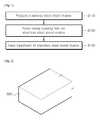
- Fig. 1 is a flowchart illustrating a method for manufacturing a metal separator for fuel cells according to one exemplary embodiment of the invention.
- operation S110 of preparing a stainless steel sheet as a matrix for a metal separator and operation S120 of forming a discontinuous coating film on the surface of the stainless steel sheet are performed.
- the discontinuous coating film is composed of nanoparticles and serves to enhance conductivity and corrosion resistance of the metal separator.
- such a discontinuous shape may expose a portion of the stainless steel sheet, thereby causing reduction of corrosion resistance.
- the method includes heat treating the stainless steel sheet in S 130 to form an oxide film on a region of the stainless steel sheet on which the discontinuous coating film has not been formed, that is, a region between the discontinuous coating films.
- the nanoparticles refer to particles having a particle size of 10 nm to 1 ⁇ m. Since the nanoparticles are coated at a density of 5 to 500 ⁇ g/cm 2 in consideration of economic feasibility for improving electrical conductivity, the coating film inevitably has a discontinuous shape. In other words, the preparation of a coating film having a higher density on the surface of the stainless steel sheet causes an increase in preparation cost.
- the coating film is discontinuously formed on the surface of the stainless steel sheet.
- the oxide film formed on a portion of the stainless steel sheet which is directly exposed to the outside is composed of at least one component selected from metal components contained in the stainless steel sheet.
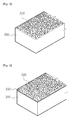
- Figs. 2 to 4 are perspective views of the metal separator in respective operations of the method of Fig. 1 .
- Fig. 5 is a sectional view of the separator of Fig. 3
- Fig. 6 is a sectional view of the separator of Fig. 4 .
- a stainless steel sheet matrix 200 is prepared.
- the stainless steel sheet matrix 200 may be a stainless steel sheet which contains 16 to 28 wt% of chromium. Specifically, the stainless steel sheet contains about 18 wt% of chromium.
- the stainless steel sheet matrix 200 includes 0.08 wt% or less of carbon (C), 16 to 28 wt% of chromium (Cr), 0.1 to 20 wt% of nickel (Ni), 0.1 to 6 wt% of molybdenum (Mo), 0.1 to 5 wt% of tungsten (W), 0.1 to 2 wt% of tin (Sn), 0.1 to 2 wt% of copper (Cu), and the balance of iron (Fe) and unavoidable impurities.
- the stainless steel sheet may be an austenite stainless steel such as SUS 316L 0.2t.
- Fig. 3 shows an operation of forming a discontinuous coating film 220 on the surface of the stainless steel sheet matrix 200.
- the discontinuous coating film 220 is formed for the following reasons.
- the discontinuous coating film 220 is formed of a material exhibiting excellent corrosion resistance and electrical conductivity.
- the separator for the fuel cell according to exemplary embodiments of the invention may be prepared to have excellent corrosion resistance and electrical conductivity not only at an initial operating stage but also after long-term operation.
- the material exhibiting excellent corrosion resistance and electrical conductivity may include any one selected from gold (Au), platinum (Pt), ruthenium (Ru), iridium (Ir), ruthenium oxide (RuO 2 ), and iridium oxide (IrO 2 ).
- the discontinuous coating film 220 may be formed by any process selected from electrolyte plating, electroless plating and a PVD process. In some embodiments, the discontinuous coating film 220 may have a coating density of 5 to 500 ⁇ g/cm 2 .
- the process of determining the coating density is an essential element and the coating density is measured as follows.
- the coating film 220 is discontinuously formed on the surface of the stainless steel sheet.
- the separator includes the coating film as shown therein.
- a process of forming an oxide film through heat treatment is performed.
- Fig. 4 is a perspective view of a heat treatment process for forming an oxide film and Fig. 6 is a sectional view of the separator shown in Fig. 4 .
- an oxide film 230 is formed on a portion of the stainless steel sheet matrix 200, on which the discontinuous coating film 220 is not formed, through heat treatment.
- the metal separator for fuel cells according to this embodiment is completely shielded by the discontinuous coating film 220 and the oxide film 230, thereby ensuring excellent corrosion resistance.
- heat treatment may be performed at 80 to 300°C for 10 minutes to 3 hours. Further, heat treatment may be performed under at least one of a vacuum, an atmosphere, and an oxygen atmosphere.
- the method according to the embodiment of the invention may provide a metal separator for fuel cells which has superior corrosion resistance and electrical conductivity not only at an initial stage but also after long-term use in operational conditions of the fuel cell.
- the metal separator for fuel cells manufactured by the method according to the embodiment of the invention includes the stainless steel sheet matrix 200, the discontinuous coating film 220 formed on the surface of the stainless steel sheet matrix 200 and composed of at least one selected from gold (Au), platinum (Pt), ruthenium (Ru), iridium (Ir), ruthenium oxide (RuO 2 ), and iridium oxide (IrO 2 ), and the oxide film 230 formed on a portion of the stainless steel sheet matrix 200 on which the discontinuous coating film 220 is not formed.
- 316L stainless steel was used as a stainless steel sheet matrix.
- a discontinuous coating film was formed on the surface of the stainless steel sheet matrix to secure electrical conductivity and an oxide film was formed thereon through heat treatment to secure corrosion resistance.
- the following experiment was performed to determine economically feasible and optimal conditions for forming a coating film and an oxide film.
- contact resistance was measured using a contact resistance tester to evaluate electrical conductivity.
- Fig. 7 is a sectional view of a contact resistance tester for measuring contact resistance of a stainless steel separator according to one exemplary embodiment of the invention.
- a modified Davies method was used to measure contact resistance between stainless steel SS and two pieces of carbon paper.
- the contact resistance was measured based on the principle of measuring four-wire current-voltage via a contact resistance tester available from Zahner Inc., Model IM6.
- Measurement of contact resistance was performed by application of DC 5 A and AC 0.5A to a measurement target through an electrode area of 25 cm 2 in a constant current mode at a frequency in the range of 10 kHz to 10 mHz.
- the carbon paper was 10 BB available from SGL Inc.
- a sample 500 was disposed between two pieces of carbon paper 520 and gold coated copper plates 510 connected to both a current supplier 530 and a voltage tester 540.
- the sample 500, carbon paper 520, and copper plates 510 were compressed to form a stack structure from both copper plates 510 of the contact resistance tester 50 using a pressure regulator (Model No. 5566, available from Instron Inc., compression maintenance test). Using the pressure regulator, a pressure of 50 to 150 N/cm 2 was applied to the contact resistance tester 50.
- Fig. 8 is a graph depicting results of evaluating contact resistance of a metal separator for fuel cells according to one exemplary embodiment of the invention.
- Fig. 8 the metal separator was not subjected to heat treatment in order to investigate conduction properties only through the coating film according to the present invention.
- the coating film was formed of gold (Au) at a coating density (Mass of Au deposit( ⁇ g/cm 2 )) of 3 to 1000 ⁇ g/cm 2 and the target value of the contact resistance (IRC) was set to 10 m ⁇ cm 2 at both sides of the separator under a pressure of 100 N/cm 2 .
- the metal separator when the coating density of gold was in the range of 5 to 500 ⁇ g/cm 2 , the metal separator exhibited desired contact resistance. Further, when comparing the contact resistance at a coating density of 500 ⁇ g/cm 2 with that at a coating density of 1000 ⁇ g/cm 2 , it can be seen that reduction in resistance is very insignificant and a coating density exceeding 500 ⁇ g/cm 2 is thus inefficient in terms of coating cost for increasing coating amount.
- the discontinuous coating film may have a coating density of 5 to 500 ⁇ g/cm 2 .
- Corrosion current density (hereinafter, "corrosion density") of the metal separator according to the present invention was measured using a corrosion current tester EG&G Model No. 273A. Tests for corrosion durability were performed in a simulated environment of a polymer electrolyte fuel cell (PEFC).
- PEFC polymer electrolyte fuel cell
- the stainless steel sheet samples were subjected to O 2 bubbling for 1 hour, and the corrosion current density thereof was measured at an open circuit potential (OCP) of-0.25V to 1V vs. SCE.
- OCP open circuit potential
- the measured properties were evaluated based on data of corrosion current at 0.6V vs. SCE in a simulated cathode environment of a fuel cell.
- the anode environment is an environment in which hydrogen is split into hydrogen ions and electrons while passing through a membrane electrode assembly (MEA), and the cathode environment is an environment in which oxygen combines with the hydrogen ions to produce water after passing through the MEA.
- MEA membrane electrode assembly
- corrosion resistance is preferably tested in the cathode environment.
- the stainless steel sheet have a corrosion current density of 1 ⁇ A/cm 2 or less for application to the PEMFC.
- Fig. 9 is a graph depicting results of evaluating corrosion current density of the metal separator for fuel cells according to the present invention.
- Fig. 9 the metal separator was subjected to heat treatment at 50 to 400°C for 30 minutes without forming the discontinuous coating film in order to evaluate pure corrosion resistance characteristics of the separator.
- the target value of corrosion current density was set to 1 ⁇ A/cm 2 or less.
- heat treatment may be performed at a temperature in the range of 80 to 300°C.
- a discontinuous gold (Au) coating film was formed at a coating density of 5 ⁇ g/cm 2 on a metal separator formed of stainless steel (316L). Heat treatment was performed at 80°C, 150°C, 200°C, 300°C and 400°C in order to evaluate the coating density according to the temperature for heat treatment. Heat treatment was performed for 30 minutes in an oxygen atmosphere.
- Example 2 The metal separator of Example 2 was obtained under the same conditions as Example 1 except that the gold (Au) coating film was formed at a coating density of 50 ⁇ g/cm 2 .
- Example 3 The metal separator of Example 3 was obtained under the same conditions as in Example 1 except that the gold (Au) coating film was formed at a coating density of 100 ⁇ g/cm 2 .
- Example 6 Each of platinum (Pt) (Example 4), iridium (Ir) (Example 5), and ruthenium (Ru) (Example 6) coating films was formed at a coating density of 50 ⁇ g/cm 2 and heat treatment was performed at 80°C for 10 minutes under vacuum.
- iridium oxide (Ir) Example 7
- ruthenium oxide (Ru) Example 8 coating films was formed at a coating density of 50 ⁇ g/cm 2 and heat treatment was performed at 100°C for 3 hours in an oxygen atmosphere.
- the metal separator of Comparative Example 1 was obtained under the same conditions as in Example 1 except that the gold (Au) coating film was formed at a coating density of 1000 ⁇ g/cm 2 .
- the metal separator of Comparative Example 2 was obtained under the same conditions as in Example 1 except that the gold coating film was formed at a coating density of 3 ⁇ g/cm 2 .
- the gold coating film was discontinuously formed at a coating density of 50 ⁇ g/cm 2 and heat treatment was performed at 50°C for 30 minutes in an atmosphere.
- EG&G Model No. 273A was used for a simulated fuel cell environment to evaluate corrosion current density of each of the metal separators for fuel cells according to Examples 1, 2 and 3 and Comparative Examples 1 and 2, EG&G Model No. 273A was used. As illustrated in Fig. 9 , heat treatment was performed at a temperature in the range of 80 to 400°C. After being immersed in 0.1N H 2 SO 4 + 2ppm HF at 80°C, stainless steel sheet samples were subjected to O 2 bubbling for 1 hour, followed by application of a constant voltage of 0.6 V vs. SCE thereto. After applying the constant voltage for a predetermined duration, the corrosion current density of each sample was measured.
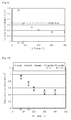
- Fig. 10 is a graph depicting results of evaluating corrosion current density of each of metal separators for fuel cells according to examples and comparative examples in a simulated fuel cell environment.
- the metal separator of Comparative Example 3 had a corrosion current density of 1.7 ⁇ g/cm 2 , which was much higher than those of the examples. Thus, it can be seen that corrosion resistance was significantly deteriorated due to heat treatment at 50°C, which was lower that the temperature for heat treatment in the examples.
- Example 1 For Comparative Example 1 in which the gold coating film was thickly formed, the corrosion current density was substantially similar to that in Example 3. Thus, it can be seen that usability is low due to insignificant improvement in efficiency through cost increase.
- Fig. 11 is a graph depicting results of evaluating contact resistance of each of the metal separators for fuel cells according to the examples and the comparative examples in a simulated fuel cell environment.
- the separator according to Comparative Example 2 did not satisfy a reference coating density and exhibited very high contact resistance. Thus, it can be seen that the separator according to Comparative Example 2 has very low electrical conductivity.
- the optimal conditions for manufacture of the metal separator for fuel cells were determined through combination of the aforementioned evaluation results, and long term durability of the metal separator for fuel cells fabricated by the method according to the present invention through application of the results was evaluated.
- Separators each having a serpentine passage for supplying reaction gases were used.
- Each fuel cell was prepared by interposing a membrane electrode assembly (Model 5710 of Gore Fuel Cell Technologies) and a gas diffusion layer (Model 10BA of SGL Ltd.) between the separators and compressing the same at a predetermined pressure.
- Performance of each of the fuel cells was evaluated using a unit cell.
- NSE Test Station 700W class was used as a fuel cell operator, and KIKUSUI E-Load was used as an electronic load for evaluating the performance of the fuel cell.
- a current cycle of 1 A/cm 2 current for 15 seconds was constantly applied for 2,000 hours.
- reaction gases hydrogen and air were supplied at a flux of maintaining a stoichiometric ratio of H 2 to air of 1.5:2.0 according to the electric current after being humidified to a relative humidity of 100 %.
- the performance of the fuel cell was evaluated at atmospheric pressure while maintaining the temperature of a humidifier and the cell at 65°C. At this time, active area was 25 cm 2 and operating pressure was 1 atm.
- Fig. 12 is a graph depicting results of evaluating long-term durability of each of the metal separators for fuel cells according to the examples and the comparative examples in a simulated fuel cell environment.
- the separator sample subjected to heat treatment at 150°C for 30 minutes in an oxygen atmosphere was used among the separator samples of Example 2 (coating density of 50 ⁇ g/cm 2 ), and the separator sample subjected to heat treatment at 150°C for 30 minutes in an oxygen atmosphere was used among the separator samples of Comparative Example 2 (coating density of 3 ⁇ g/cm 2 ). Further, the separator of Example 3 was subjected to evaluation of long-term durability of a fuel cell in a simulated fuel cell environment. Evaluation results are shown in Fig. 12 .
- the fuel cell of Comparative Example 2 generated a voltage of about 0.59V, which was much lower than the 0.69 V of Example 2, upon application of a current density of 1 A/cm 2 , and both exhibited similar difference in voltage generation after 2,000 hours. This result was caused by lower electrical conductivity of Comparative Example 2 than that of Example 2. In other words, since the metal separator of Comparative Example 2 had a significantly higher contact resistance, the fuel cell of Comparative Example 2 exhibited significantly low performance even at an initial stage.
- the fuel cell of Comparative Example 3 generated a voltage similar to that of Example 2 at an initial operating stage but underwent significant reduction in generation of voltage over time. This result was caused by low corrosion resistance regardless of similar electrical conductivity.
- the method for manufacturing a metal separator for fuel cells according to the present invention enables surface modification to obtain excellent durability even with a general inexpensive stainless steel sheet, thereby lowering manufacturing costs of the metal separator while improving efficiency thereof.
Abstract
Description
- The present invention relates to a metal separator for a fuel cell and a method for manufacturing the same, and more particularly to a metal separator for a polymer electrolyte membrane fuel cell (PEMFC) that has a coating film formed on the surface of the separator to provide excellent corrosion resistance, electrical conductivity and durability, and a method for manufacturing the same.
- In general, since a unit cell of a fuel cell generates too low a voltage to be used alone in practice, the fuel cell has several to several hundred unit cells stacked therein. When stacking the unit cells, a separator or bipolar plate is used to facilitate electrical connection between the unit cells and to separate reaction gases.
- The bipolar plate is an essential component of a fuel cell along with a membrane electrode assembly (MEA) and performs a variety of functions such as structural support for the MEA and gas diffusion layer (GDLs), collection and transmission of electric current, transmission and removal of reaction gas, transmission of cooling water used for removal of heat, and the like.
- Hence, it is necessary for materials of the separator to have excellent electrical and thermal conductivity, air-tightness, chemical stability, and the like.
- Generally, graphite materials and composite graphite materials consisting of a resin and graphite mixture are used to form the separator.
- However, graphite materials exhibit lower strength and air-tightness than metallic materials, and suffer from higher manufacturing costs and lower productivity when applied to manufacture of separators. Recently, metallic separators have been actively investigated to overcome such problems of graphite separators.
- When a separator is made of a metallic material, there are many advantages in that volume and weight reduction of a fuel cell stack can be accomplished via thickness reduction of the separator, and in that the separator can be fabricated by stamping, which facilitates mass production of the separators.
- In this case, however, the metallic material inevitably undergoes corrosion during use of the fuel cell, causing contamination of the MEA and performance deterioration of the fuel cell stack. Further, a thick oxide film can form on the surface of the metallic material after extended use of the fuel cell, causing an increase in internal resistance of the fuel cell.
- Stainless steel, titanium alloys, aluminum alloys, nickel alloys, and the like have been proposed as candidate materials for the separator of the fuel cell. Among these materials, stainless steel has received attention for its lower price and good corrosion resistance, but further improvements in corrosion resistance and electrical conductivity are still needed.
- The present invention is directed to providing a metal separator for fuel cells that has corrosion resistance and contact resistance satisfying the standards set by the Department of Energy (DOE) not only at an initial stage but also after being exposed to high temperature/high humidity conditions in the fuel cell for a long period of time, and a method for manufacturing the same.
- The technical problems of the present invention are not limited to the foregoing problems, and other technical problems will be clearly understood by those skilled in the art from the following description.
- In accordance with an aspect of the present invention, a method for manufacturing a metal separator for fuel cells includes: preparing a stainless steel sheet as a matrix of the metal separator; forming a discontinuous coating film on the surface of the stainless steel sheet, the coating film being composed of at least one selected from gold (Au), platinum (Pt), ruthenium (Ru), iridium (Ir), ruthenium oxide (RuO2), and iridium oxide (IrO2); and heat treating the stainless steel sheet having the discontinuous coating film to form an oxide film on a portion of the stainless steel sheet on which the coating film is not formed.
- The discontinuous coating film may have a coating density of 5 to 500 µg/cm2, and the heat treatment may be performed at a temperature of 80 to 300°C. The discontinuous coating film may be composed of nanoparticles, and the stainless steel sheet may include 0.08 wt% or less of carbon (C), 16 to 28 wt% of chromium (Cr), 0.1 to 20 wt% of nickel (Ni), 0.1 to 6 wt% of molybdenum (Mo), 0.1 to 5 wt% of tungsten (W), 0.1 to 2 wt% of tin (Sn), 0.1 to 2 wt% of copper (Cu), and the balance of iron (Fe) and unavoidable impurities. Heat treatment may be performed for 10 minutes to 3 hours. Further, heat treatment may be performed under at least one of a vacuum, an atmosphere, and an oxygen atmosphere.
- In accordance with another aspect of the present invention, a metal separator for fuel cells includes: a stainless steel sheet as a matrix of the metal separator; a discontinuous coating film formed on the surface of the stainless steel sheet, the coating film being composed of at least one selected from gold (Au), platinum (Pt), ruthenium (Ru), iridium (Ir), ruthenium oxide (RuO2), and iridium oxide (IrO2); and an oxide film formed on a portion of the stainless steel sheet on which the coating film is not formed.
- The metal separator may have a corrosion current density of 1 µA/cm2 or less and a contact resistance of 10 mΩ.cm2 or less on both surfaces thereof.
- The metal separator for fuel cells according to embodiments of the invention has excellent corrosion resistance and electrical conductivity not only at an initial stage but also after long-term use in operational conditions of the fuel cell.
- In addition, the method for manufacturing a metal separator for fuel cells according to embodiments of the invention allows surface modification to obtain excellent durability even with a general inexpensive stainless steel sheet, thereby lowering manufacturing costs of the metal separator.
- The metal separator for fuel cells according to the embodiments of the invention has a corrosion current density of 1 µA/cm2 or less and a contact resistance of 10 mΩ.cm2 or less on both surfaces of the separator.
-
-
Fig. 1 is a flowchart illustrating a method for manufacturing a metal separator for fuel cells according to one exemplary embodiment of the present invention; -
Figs. 2 to 4 are perspective views of the metal separator in respective operations of the method ofFig. 1 ; -
Fig. 5 is a sectional view of the separator ofFig. 3 ; -
Fig. 6 is a sectional view of the separator ofFig. 4 ; -
Fig. 7 is a schematic view of a contact resistance tester for measuring contact resistance of a stainless steel sheet according to the present invention; -
Fig. 8 is a graph depicting results of evaluating contact resistance of a metal separator for fuel cells according to the present invention; -
Fig. 9 is a graph depicting results of evaluating corrosion current density of a metal separator for fuel cells according to the present invention; -
Fig. 10 is a graph depicting results of evaluating corrosion current density of each of metal separators for fuel cells according to examples and comparative examples in a simulated fuel cell environment; -
Fig. 11 is a graph depicting results of evaluating contact resistance of each of the metal separators for fuel cells according to the examples and the comparative examples in a simulated fuel cell environment; and -
Fig. 12 is a graph depicting results of evaluating long-term durability of each of the metal separators for fuel cells according to the examples and the comparative examples in a simulated fuel cell environment. - Exemplary embodiments of the present invention will now be described in detail with reference to the accompanying drawings.
- It should be understood that the drawings are not to precise scale and may be exaggerated in thickness of lines or size of components for descriptive convenience and clarity only. Further, it should be understood that when a layer or film is referred to as being "on" another layer or film, it can be directly on the other layer or film, or intervening layers may also be present.
-
Fig. 1 is a flowchart illustrating a method for manufacturing a metal separator for fuel cells according to one exemplary embodiment of the invention. - Referring to
Fig. 1 , operation S110 of preparing a stainless steel sheet as a matrix for a metal separator and operation S120 of forming a discontinuous coating film on the surface of the stainless steel sheet are performed. In this embodiment, the discontinuous coating film is composed of nanoparticles and serves to enhance conductivity and corrosion resistance of the metal separator. However, such a discontinuous shape may expose a portion of the stainless steel sheet, thereby causing reduction of corrosion resistance. Thus, according to this embodiment, the method includes heat treating the stainless steel sheet inS 130 to form an oxide film on a region of the stainless steel sheet on which the discontinuous coating film has not been formed, that is, a region between the discontinuous coating films. - Here, the nanoparticles refer to particles having a particle size of 10 nm to 1 µm. Since the nanoparticles are coated at a density of 5 to 500 µg/cm2 in consideration of economic feasibility for improving electrical conductivity, the coating film inevitably has a discontinuous shape. In other words, the preparation of a coating film having a higher density on the surface of the stainless steel sheet causes an increase in preparation cost.
- Thus, in order to reduce the preparation cost as much as possible, the coating film is discontinuously formed on the surface of the stainless steel sheet.
- As a result, the surface of the stainless steel sheet is partially exposed to the outside.
- Furthermore, the oxide film formed on a portion of the stainless steel sheet which is directly exposed to the outside is composed of at least one component selected from metal components contained in the stainless steel sheet.
- Next, the method for manufacturing a metal separator according to the exemplary embodiment of the invention will be described in more detail.
-
Figs. 2 to 4 are perspective views of the metal separator in respective operations of the method ofFig. 1 . In addition,Fig. 5 is a sectional view of the separator ofFig. 3 andFig. 6 is a sectional view of the separator ofFig. 4 . - Referring to
Fig. 2 , in order to fabricate a metal separator for fuel cells according to one exemplary embodiment, a stainlesssteel sheet matrix 200 is prepared. - In this embodiment, the stainless
steel sheet matrix 200 may be a stainless steel sheet which contains 16 to 28 wt% of chromium. Specifically, the stainless steel sheet contains about 18 wt% of chromium. - More specifically, the stainless
steel sheet matrix 200 includes 0.08 wt% or less of carbon (C), 16 to 28 wt% of chromium (Cr), 0.1 to 20 wt% of nickel (Ni), 0.1 to 6 wt% of molybdenum (Mo), 0.1 to 5 wt% of tungsten (W), 0.1 to 2 wt% of tin (Sn), 0.1 to 2 wt% of copper (Cu), and the balance of iron (Fe) and unavoidable impurities. In some embodiments, the stainless steel sheet may be an austenite stainless steel such as SUS 316L 0.2t. - Next,
Fig. 3 shows an operation of forming adiscontinuous coating film 220 on the surface of the stainlesssteel sheet matrix 200. In this embodiment, thediscontinuous coating film 220 is formed for the following reasons. - When the surface of the stainless
steel sheet matrix 200 is exposed for long durations to high temperature/high humidity operating conditions of a fuel cell, metal oxides are formed on the surface of the stainlesssteel sheet matrix 200. The metal oxides can maintain corrosion resistance but have a negative influence on electrical conductivity. Therefore, according to the present invention, thediscontinuous coating film 220 is formed of a material exhibiting excellent corrosion resistance and electrical conductivity. As a result, the separator for the fuel cell according to exemplary embodiments of the invention may be prepared to have excellent corrosion resistance and electrical conductivity not only at an initial operating stage but also after long-term operation. - In some embodiments, the material exhibiting excellent corrosion resistance and electrical conductivity may include any one selected from gold (Au), platinum (Pt), ruthenium (Ru), iridium (Ir), ruthenium oxide (RuO2), and iridium oxide (IrO2).
- In some embodiments, the
discontinuous coating film 220 may be formed by any process selected from electrolyte plating, electroless plating and a PVD process. In some embodiments, thediscontinuous coating film 220 may have a coating density of 5 to 500 µg/cm2. - If the coating density is less than 5 µg/cm2, it can be difficult to secure a desired degree of electrical conductivity. If the coating density exceeds 500 µg/cm2, the effect of improving electrical conductivity is not obtained in proportion to the increase of the coating amount. Thus, in the present invention, the process of determining the coating density is an essential element and the coating density is measured as follows.
- When the coating film is formed of gold (Au), a steel sheet matrix (metal separator) coated with gold nanoparticles is dissolved in 3 liters of aqua regia and the concentration of gold ions is measured using atomic absorption spectroscopy (AAS) to calculate the coating density of gold (Au) according to Equation 1:

- As shown in
Figs. 3 and5 , thecoating film 220 is discontinuously formed on the surface of the stainless steel sheet. Generally, it is possible to secure desired characteristics of the metal separator when the separator includes the coating film as shown therein. However, in order to ensure that the metal separator has a corrosion current density of 1 µA/cm2 or less and a contact resistance of 10 mΩ·cm2 or less on both surfaces thereof, a process of forming an oxide film through heat treatment is performed. -
Fig. 4 is a perspective view of a heat treatment process for forming an oxide film andFig. 6 is a sectional view of the separator shown inFig. 4 . - Referring to
Figs. 4 and6 , anoxide film 230 is formed on a portion of the stainlesssteel sheet matrix 200, on which thediscontinuous coating film 220 is not formed, through heat treatment. - As such, the metal separator for fuel cells according to this embodiment is completely shielded by the
discontinuous coating film 220 and theoxide film 230, thereby ensuring excellent corrosion resistance. - In some embodiments, heat treatment may be performed at 80 to 300°C for 10 minutes to 3 hours. Further, heat treatment may be performed under at least one of a vacuum, an atmosphere, and an oxygen atmosphere.
- The method according to the embodiment of the invention may provide a metal separator for fuel cells which has superior corrosion resistance and electrical conductivity not only at an initial stage but also after long-term use in operational conditions of the fuel cell.
- Consequently, the metal separator for fuel cells manufactured by the method according to the embodiment of the invention includes the stainless
steel sheet matrix 200, thediscontinuous coating film 220 formed on the surface of the stainlesssteel sheet matrix 200 and composed of at least one selected from gold (Au), platinum (Pt), ruthenium (Ru), iridium (Ir), ruthenium oxide (RuO2), and iridium oxide (IrO2), and theoxide film 230 formed on a portion of the stainlesssteel sheet matrix 200 on which thediscontinuous coating film 220 is not formed. - Next, a description of the present invention will be given with reference to inventive examples and comparative examples. Further, measurement of corrosion resistance and electrical conductivity of the metal separator will be described with reference to a process of measuring corrosion current density and a process of measuring contact resistance.
- 316L stainless steel was used as a stainless steel sheet matrix. A discontinuous coating film was formed on the surface of the stainless steel sheet matrix to secure electrical conductivity and an oxide film was formed thereon through heat treatment to secure corrosion resistance. Here, the following experiment was performed to determine economically feasible and optimal conditions for forming a coating film and an oxide film.
- First, contact resistance was measured using a contact resistance tester to evaluate electrical conductivity.
-
Fig. 7 is a sectional view of a contact resistance tester for measuring contact resistance of a stainless steel separator according to one exemplary embodiment of the invention. - Referring to
Fig. 7 , in order to determine optimal parameters for cell assembly through measurement of contact resistance of astainless steel sheet 500, a modified Davies method was used to measure contact resistance between stainless steel SS and two pieces of carbon paper. - The contact resistance was measured based on the principle of measuring four-wire current-voltage via a contact resistance tester available from Zahner Inc., Model IM6.
- Measurement of contact resistance was performed by application of DC 5 A and AC 0.5A to a measurement target through an electrode area of 25 cm2 in a constant current mode at a frequency in the range of 10 kHz to 10 mHz. The carbon paper was 10 BB available from SGL Inc.
- In the
contact resistance tester 50, asample 500 was disposed between two pieces ofcarbon paper 520 and gold coatedcopper plates 510 connected to both acurrent supplier 530 and avoltage tester 540. - Next, voltage was measured by applying DC 5A/AC 0.5A to the
sample 500 through an electrode area of 25 cm2 using a current supplier 530 (available from Zahner Inc., Model IM6). - Then, the
sample 500,carbon paper 520, andcopper plates 510 were compressed to form a stack structure from bothcopper plates 510 of thecontact resistance tester 50 using a pressure regulator (Model No. 5566, available from Instron Inc., compression maintenance test). Using the pressure regulator, a pressure of 50 to 150 N/cm2 was applied to thecontact resistance tester 50. - The results of measurement using the
contact resistance tester 50 are shown inFig. 8 . -
Fig. 8 is a graph depicting results of evaluating contact resistance of a metal separator for fuel cells according to one exemplary embodiment of the invention. - In
Fig. 8 , the metal separator was not subjected to heat treatment in order to investigate conduction properties only through the coating film according to the present invention. - The coating film was formed of gold (Au) at a coating density (Mass of Au deposit(µg/cm2)) of 3 to 1000 µg/cm2 and the target value of the contact resistance (IRC) was set to 10 mΩ·cm2 at both sides of the separator under a pressure of 100 N/cm2.
- Referring to
Fig. 8 , when the coating density of gold was in the range of 5 to 500 µg/cm2, the metal separator exhibited desired contact resistance. Further, when comparing the contact resistance at a coating density of 500 µg/cm2 with that at a coating density of 1000 µg/cm2, it can be seen that reduction in resistance is very insignificant and a coating density exceeding 500 µg/cm2 is thus inefficient in terms of coating cost for increasing coating amount. - Therefore, according to the present invention, the discontinuous coating film may have a coating density of 5 to 500 µg/cm2.
- Next, the corrosion current density was measured in order to evaluate influence of heat treatment on the metal separator for fuel cells according to the present invention.
- Corrosion current density (hereinafter, "corrosion density") of the metal separator according to the present invention was measured using a corrosion current tester EG&G Model No. 273A. Tests for corrosion durability were performed in a simulated environment of a polymer electrolyte fuel cell (PEFC).
- After being etched at 80°C with 0.1N H2SO4 + 2ppm HF as an etching solution, the stainless steel sheet samples were subjected to O2 bubbling for 1 hour, and the corrosion current density thereof was measured at an open circuit potential (OCP) of-0.25V to 1V vs. SCE.
- Further, other physical properties were measured at -0.24V vs. SCE (saturated calomel electrode) for a PEFC anode environment and at 0.6V vs. SCE for a PEFC cathode environment.
- Here, the measured properties were evaluated based on data of corrosion current at 0.6V vs. SCE in a simulated cathode environment of a fuel cell.
- The anode environment is an environment in which hydrogen is split into hydrogen ions and electrons while passing through a membrane electrode assembly (MEA), and the cathode environment is an environment in which oxygen combines with the hydrogen ions to produce water after passing through the MEA.
- Since the cathode environment has a high potential and is a very corrosive environment, corrosion resistance is preferably tested in the cathode environment.
- Further, it is desirable that the stainless steel sheet have a corrosion current density of 1 µA/cm2 or less for application to the PEMFC.
-
Fig. 9 is a graph depicting results of evaluating corrosion current density of the metal separator for fuel cells according to the present invention. - In
Fig. 9 , the metal separator was subjected to heat treatment at 50 to 400°C for 30 minutes without forming the discontinuous coating film in order to evaluate pure corrosion resistance characteristics of the separator. Here, the target value of corrosion current density was set to 1 µA/cm2 or less. As a result, upon heat treatment at 50°C, the corrosion current exceeded the reference value, and upon heat treatment at 80°C or more, desired corrosion resistance could be obtained. - In addition, when comparing the corrosion density at 300°C with the corrosion density at 400°C, reduction in corrosion current density was very insignificant. As the temperature for heat treatment increases, energy consumption for heating increases. Thus, it can be seen that since there is no significant variation in corrosion current density for heat treatment at a temperature exceeding 300°C, usability of heat treatment is lowered. Therefore, according to the present invention, heat treatment may be performed at a temperature in the range of 80 to 300°C.
- In this invention, optimal conditions were determined through experimentation and suitability of these conditions was evaluated with reference to examples and comparative examples described below.
- A discontinuous gold (Au) coating film was formed at a coating density of 5 µg/cm2 on a metal separator formed of stainless steel (316L). Heat treatment was performed at 80°C, 150°C, 200°C, 300°C and 400°C in order to evaluate the coating density according to the temperature for heat treatment. Heat treatment was performed for 30 minutes in an oxygen atmosphere.
- The metal separator of Example 2 was obtained under the same conditions as Example 1 except that the gold (Au) coating film was formed at a coating density of 50 µg/cm2.
- The metal separator of Example 3 was obtained under the same conditions as in Example 1 except that the gold (Au) coating film was formed at a coating density of 100 µg/cm2.
- Each of platinum (Pt) (Example 4), iridium (Ir) (Example 5), and ruthenium (Ru) (Example 6) coating films was formed at a coating density of 50 µg/cm2 and heat treatment was performed at 80°C for 10 minutes under vacuum.
- Each of iridium oxide (Ir) (Example 7) and ruthenium oxide (Ru) (Example 8) coating films was formed at a coating density of 50 µg/cm2 and heat treatment was performed at 100°C for 3 hours in an oxygen atmosphere.
- The metal separator of Comparative Example 1 was obtained under the same conditions as in Example 1 except that the gold (Au) coating film was formed at a coating density of 1000 µg/cm2.
- The metal separator of Comparative Example 2 was obtained under the same conditions as in Example 1 except that the gold coating film was formed at a coating density of 3 µg/cm2.
- The gold coating film was discontinuously formed at a coating density of 50 µg/cm2 and heat treatment was performed at 50°C for 30 minutes in an atmosphere.
- For a simulated fuel cell environment to evaluate corrosion current density of each of the metal separators for fuel cells according to Examples 1, 2 and 3 and Comparative Examples 1 and 2, EG&G Model No. 273A was used. As illustrated in
Fig. 9 , heat treatment was performed at a temperature in the range of 80 to 400°C. After being immersed in 0.1N H2SO4 + 2ppm HF at 80°C, stainless steel sheet samples were subjected to O2 bubbling for 1 hour, followed by application of a constant voltage of 0.6 V vs. SCE thereto. After applying the constant voltage for a predetermined duration, the corrosion current density of each sample was measured. -
Fig. 10 is a graph depicting results of evaluating corrosion current density of each of metal separators for fuel cells according to examples and comparative examples in a simulated fuel cell environment. - As can be seen from
Fig. 10 , all of the metal separators according to the examples exhibited relatively stable characteristics through heat treatment after forming the gold coating film. - Further, although not shown in the figure, the metal separator of Comparative Example 3 had a corrosion current density of 1.7 µg/cm2, which was much higher than those of the examples. Thus, it can be seen that corrosion resistance was significantly deteriorated due to heat treatment at 50°C, which was lower that the temperature for heat treatment in the examples.
- For Comparative Example 1 in which the gold coating film was thickly formed, the corrosion current density was substantially similar to that in Example 3. Thus, it can be seen that usability is low due to insignificant improvement in efficiency through cost increase.
- A simulated fuel cell environment to evaluate contact resistance of each of the metal separators for fuel cells according to Examples 1, 2 and 3 and Comparative Examples 1 and 2 was the same as in
Fig. 8 , and results thereof are shown inFig. 11 . -
Fig. 11 is a graph depicting results of evaluating contact resistance of each of the metal separators for fuel cells according to the examples and the comparative examples in a simulated fuel cell environment. - Referring to
Fig. 11 , when the discontinuous coating film according to the invention was formed, the separator according to Comparative Example 2 did not satisfy a reference coating density and exhibited very high contact resistance. Thus, it can be seen that the separator according to Comparative Example 2 has very low electrical conductivity. - Further, for Comparative Example 1 in which the coating density exceeded the reference value, the contact resistance was substantially the same as that in Example 3. Thus, it can be seen that usability is low due to insignificant improvement in efficiency through cost increase.
- As such, the optimal conditions for manufacture of the metal separator for fuel cells were determined through combination of the aforementioned evaluation results, and long term durability of the metal separator for fuel cells fabricated by the method according to the present invention through application of the results was evaluated.
- Separators each having a serpentine passage for supplying reaction gases were used. Each fuel cell was prepared by interposing a membrane electrode assembly (Model 5710 of Gore Fuel Cell Technologies) and a gas diffusion layer (Model 10BA of SGL Ltd.) between the separators and compressing the same at a predetermined pressure.
- Performance of each of the fuel cells was evaluated using a unit cell. NSE Test Station 700W class was used as a fuel cell operator, and KIKUSUI E-Load was used as an electronic load for evaluating the performance of the fuel cell. A current cycle of 1 A/cm2 current for 15 seconds was constantly applied for 2,000 hours.
- As the reaction gases, hydrogen and air were supplied at a flux of maintaining a stoichiometric ratio of H2 to air of 1.5:2.0 according to the electric current after being humidified to a relative humidity of 100 %. The performance of the fuel cell was evaluated at atmospheric pressure while maintaining the temperature of a humidifier and the cell at 65°C. At this time, active area was 25 cm2 and operating pressure was 1 atm.
-
Fig. 12 is a graph depicting results of evaluating long-term durability of each of the metal separators for fuel cells according to the examples and the comparative examples in a simulated fuel cell environment. - In this evaluation, the separator sample subjected to heat treatment at 150°C for 30 minutes in an oxygen atmosphere was used among the separator samples of Example 2 (coating density of 50 µg/cm2), and the separator sample subjected to heat treatment at 150°C for 30 minutes in an oxygen atmosphere was used among the separator samples of Comparative Example 2 (coating density of 3 µg/cm2). Further, the separator of Example 3 was subjected to evaluation of long-term durability of a fuel cell in a simulated fuel cell environment. Evaluation results are shown in
Fig. 12 . - In addition, the separators of Examples 4 to 8 were subjected to evaluation of long-term durability of a fuel cell and evaluation results are listed in Table 1.
Table 1 Performance of fuel cell (V@1A/cm2) 0 hour 2,000 hours Example 4 0.68 0.67 Example 5 0.68 0.67 Example 6 0.69 0.68 Example 7 0.68 0.67 Example 8 0.69 0.67 - First, referring to
Fig. 12 , the fuel cell of Comparative Example 2 generated a voltage of about 0.59V, which was much lower than the 0.69 V of Example 2, upon application of a current density of 1 A/cm2, and both exhibited similar difference in voltage generation after 2,000 hours. This result was caused by lower electrical conductivity of Comparative Example 2 than that of Example 2. In other words, since the metal separator of Comparative Example 2 had a significantly higher contact resistance, the fuel cell of Comparative Example 2 exhibited significantly low performance even at an initial stage. - Further, the fuel cell of Comparative Example 3 generated a voltage similar to that of Example 2 at an initial operating stage but underwent significant reduction in generation of voltage over time. This result was caused by low corrosion resistance regardless of similar electrical conductivity.
- Next, as can be seen from the results of Table 1, all of the fuel cells according to the examples exhibited similar durability. This result is also shown in
Fig. 12 , and it can be seen that the fuel cells according to the examples exhibit superior performance to those of the comparative examples. - Therefore, the method for manufacturing a metal separator for fuel cells according to the present invention enables surface modification to obtain excellent durability even with a general inexpensive stainless steel sheet, thereby lowering manufacturing costs of the metal separator while improving efficiency thereof.
Claims (11)
- A method for manufacturing a metal separator for fuel cells, comprising:preparing a stainless steel sheet as a matrix of the metal separator;forming a discontinuous coating film on the surface of the stainless steel sheet, the coating film being composed of at least one selected from gold (Au), platinum (Pt), ruthenium (Ru), iridium (Ir), ruthenium oxide (RuO2), and iridium oxide (IrO2); andheat treating the stainless steel sheet having the discontinuous coating film to form an oxide film on a portion of the stainless steel sheet on which the coating film is not formed.
- The method of claim 1, wherein the discontinuous coating film has a coating density of 5 to 500 µg/cm2.
- The method of claim 1, wherein the heat treatment is performed at a temperature of 80 to 300°C.
- The method of claim 1, wherein the discontinuous coating film is composed of nanoparticles.
- The method of claim 1, wherein the stainless steel sheet comprises 0.08 wt% or less of carbon (C), 16 to 28 wt% of chromium (Cr), 0.1 to 20 wt% of nickel (Ni), 0.1 to 6 wt% of molybdenum (Mo), 0.1 to 5 wt% of tungsten (W), 0.1 to 2 wt% of tin (Sn), 0.1 to 2 wt% of copper (Cu), and the balance of iron (Fe) and unavoidable impurities.
- The method of claim 1, wherein the heat treatment is performed for 10 minutes to 3 hours.
- The method of claim 1, wherein the heat treatment is performed under at least one of a vacuum, an atmosphere, and an oxygen atmosphere.
- A metal separator for fuel cells comprising:a stainless steel sheet as a matrix of the metal separator;a discontinuous coating film formed on the surface of the stainless steel sheet, the coating film being composed of at least one selected from gold (Au), platinum (Pt), ruthenium (Ru), iridium (Ir), ruthenium oxide (RuO2), and iridium oxide (IrO2); andan oxide film formed on a portion of the stainless steel sheet on which the coating film is not formed.
- The metal separator of claim 8, wherein the discontinuous coating film has a coating density of 5 to 500 µg/cm2.
- The metal separator of claim 8, wherein the discontinuous coating film is composed of nanoparticles.
- The metal separator of claim 8, wherein the stainless steel sheet comprises 0.08 wt% or less of carbon (C), 16 to 28 wt% of chromium (Cr), 0.1 to 20 wt% of nickel (Ni), 0.1 to 6 wt% of molybdenum (Mo), 0.1 to 5 wt% of tungsten (W), 0.1 to 2 wt% of tin (Sn), 0.1 to 2 wt% of copper (Cu), and the balance of iron (Fe) and unavoidable impurities.
Applications Claiming Priority (2)
| Application Number | Priority Date | Filing Date | Title |
|---|---|---|---|
| KR20090077832A KR101165542B1 (en) | 2009-08-21 | 2009-08-21 | Metal separator for fuel cell having coating film and method for the same |
| PCT/KR2010/005525 WO2011021881A2 (en) | 2009-08-21 | 2010-08-20 | Metal separator plate for fuel cell having coating film formed on surface and method for producing same |
Publications (3)
| Publication Number | Publication Date |
|---|---|
| EP2469634A2 true EP2469634A2 (en) | 2012-06-27 |
| EP2469634A4 EP2469634A4 (en) | 2014-12-03 |
| EP2469634B1 EP2469634B1 (en) | 2019-03-13 |
Family
ID=43607495
Family Applications (1)
| Application Number | Title | Priority Date | Filing Date |
|---|---|---|---|
| EP10810189.0A Active EP2469634B1 (en) | 2009-08-21 | 2010-08-20 | Metal separator plate for fuel cell having coating film formed on surface and method for producing same |
Country Status (12)
| Country | Link |
|---|---|
| US (1) | US8778566B2 (en) |
| EP (1) | EP2469634B1 (en) |
| JP (1) | JP5734291B2 (en) |
| KR (1) | KR101165542B1 (en) |
| CN (1) | CN102484261B (en) |
| AU (1) | AU2010284790B2 (en) |
| BR (1) | BR112012003731B1 (en) |
| CA (1) | CA2771696C (en) |
| MX (1) | MX2012002218A (en) |
| RU (1) | RU2521077C2 (en) |
| SG (1) | SG178849A1 (en) |
| WO (1) | WO2011021881A2 (en) |
Cited By (2)
| Publication number | Priority date | Publication date | Assignee | Title |
|---|---|---|---|---|
| EP2768055A1 (en) | 2013-02-15 | 2014-08-20 | Commissariat A L'energie Atomique Et Aux Energies Alternatives | Bipolar metal plate for fuel cell with proton exchange membrane |
| EP3396758A4 (en) * | 2015-12-24 | 2018-11-21 | JFE Steel Corporation | Stainless steel sheet for fuel cell separators and method for producing same |
Families Citing this family (16)
| Publication number | Priority date | Publication date | Assignee | Title |
|---|---|---|---|---|
| JP5201256B1 (en) * | 2011-11-18 | 2013-06-05 | 新日鐵住金株式会社 | Titanium material for polymer electrolyte fuel cell separator, production method thereof, and polymer electrolyte fuel cell using the same |
| KR101357433B1 (en) * | 2012-05-15 | 2014-02-04 | 현대하이스코 주식회사 | Method for judging adhesion of discontinuous coating layer formed of in surface of metal- biopolar plate for a fuel cell |
| KR101410944B1 (en) * | 2012-12-21 | 2014-06-23 | 주식회사 포스코 | Fabrication of stainless steel for PEMFC bipolar plate |
| EP3139431A4 (en) * | 2014-06-16 | 2017-12-13 | Nippon Steel & Sumitomo Metal Corporation | Titanium material for separator of polymer electrolyte fuel cell, separator comprising same, and polymer electrolyte fuel cell equipped therewith |
| US10003089B2 (en) | 2015-02-11 | 2018-06-19 | Ford Global Technologies, Llc | Multilayer coating for corrosion resistant metal bipolar plate for a PEMFC |
| US10135077B2 (en) | 2015-02-12 | 2018-11-20 | Ford Global Technologies, Llc | Corrosion resistant metal bipolar plate for a PEMFC including a radical scavenger |
| MX2019009514A (en) | 2017-02-09 | 2019-11-05 | Jfe Steel Corp | Stainless steel plate substrate of steel plate for fuel cell separator, and method for producing same. |
| CN107681173A (en) * | 2017-08-03 | 2018-02-09 | 上海交通大学 | A kind of point-like conduction composite coating for fuel battery metal pole plate |
| GB201910455D0 (en) * | 2019-07-22 | 2019-09-04 | Teer Coatings Ltd | Coating for the surface of an article and process for forming the coating |
| KR102326043B1 (en) | 2019-12-19 | 2021-11-15 | 주식회사 포스코 | Stainless steel for polymer fuel cell separator with excellent corrosion resistance |
| DE102020210209A1 (en) | 2020-08-12 | 2022-02-17 | Ekpo Fuel Cell Technologies Gmbh | Bipolar plate, fuel cell and method for manufacturing a bipolar plate |
| KR102571306B1 (en) | 2021-05-28 | 2023-09-01 | 서진산업 주식회사 | Metallic Separator gasket for fuel cell using Multimaterial |
| WO2023080675A1 (en) * | 2021-11-04 | 2023-05-11 | 현대제철 주식회사 | Separator, having metal coating layer thereon, for fuel cell and manufacturing method therefor |
| KR20230127661A (en) | 2022-02-25 | 2023-09-01 | 주식회사 세종이브이 | Carbon layer for metal separator of fuel cell |
| KR20230127658A (en) | 2022-02-25 | 2023-09-01 | 주식회사 세종이브이 | Metal separator for fuel cell |
| DE102022108476A1 (en) | 2022-04-07 | 2023-10-12 | Ekpo Fuel Cell Technologies Gmbh | Bipolar plate, fuel cell and method for producing a bipolar plate |
Citations (4)
| Publication number | Priority date | Publication date | Assignee | Title |
|---|---|---|---|---|
| JPH11260382A (en) * | 1998-03-09 | 1999-09-24 | Nisshin Steel Co Ltd | Separator for low-temperature fuel cell |
| EP1235288A1 (en) * | 1999-09-17 | 2002-08-28 | Matsushita Electric Industrial Co., Ltd. | Polymer electrolyte fuel cell |
| US20070141370A1 (en) * | 2005-06-14 | 2007-06-21 | Material Interface, Inc. | Nanoparticle surface treatment |
| JP2008108685A (en) * | 2006-09-29 | 2008-05-08 | Kobe Steel Ltd | Manufacturing method of fuel cell separator, fuel cell separator, and fuel cell |
Family Cites Families (18)
| Publication number | Priority date | Publication date | Assignee | Title |
|---|---|---|---|---|
| RU2100877C1 (en) * | 1996-08-19 | 1997-12-27 | Александр Петрович Павлов | Chemical power supply separator |
| BR9815251B1 (en) * | 1997-10-14 | 2009-05-05 | separator for a low temperature fuel cell and process for its manufacture. | |
| JP2001297777A (en) | 2000-04-13 | 2001-10-26 | Matsushita Electric Ind Co Ltd | Macromolecular electrolyte fuel cell |
| JP3857873B2 (en) | 2000-11-09 | 2006-12-13 | 三洋電機株式会社 | FUEL CELL SEPARATOR, ITS MANUFACTURING METHOD, AND FUEL CELL |
| WO2003026052A1 (en) * | 2001-09-18 | 2003-03-27 | Furuya Metal Co., Ltd. | Bipolar plate for fuel cell and method for production thereof |
| CN1290219C (en) * | 2001-12-18 | 2006-12-13 | 本田技研工业株式会社 | Method of producing fuel cell-use separator and device for producing it |
| JP3930393B2 (en) * | 2002-08-06 | 2007-06-13 | 本田技研工業株式会社 | Metal separator for fuel cell and manufacturing method thereof |
| JP4494155B2 (en) * | 2004-09-29 | 2010-06-30 | 日本高純度化学株式会社 | Gold-plated structure and fuel cell separator comprising this gold-plated structure |
| US20090042084A1 (en) * | 2005-06-03 | 2009-02-12 | Koji Kobayashi | Separator for fuel cell and method for manufacturing the same |
| JP4557911B2 (en) * | 2006-03-07 | 2010-10-06 | 株式会社東芝 | Communication apparatus and communication method |
| KR101102905B1 (en) * | 2006-04-14 | 2012-01-11 | 어플라이드 머티어리얼스, 인코포레이티드 | Reliable fuel cell electrode design |
| JP2007323988A (en) * | 2006-06-01 | 2007-12-13 | Daido Steel Co Ltd | Metal separator for fuel cell, manufacturing method of the same, and fuel cell |
| JP2008004498A (en) * | 2006-06-26 | 2008-01-10 | Mitsubishi Materials Corp | Composite layer-covered metal plate with less ncreases in contact resistance even if exposed to oxidative environment for long period |
| JP4551429B2 (en) | 2006-09-29 | 2010-09-29 | 株式会社神戸製鋼所 | Method for manufacturing fuel cell separator, fuel cell separator and fuel cell |
| KR101107862B1 (en) | 2006-12-21 | 2012-01-31 | 가부시키가이샤 고베 세이코쇼 | Alloy coating film for metal separator of fuel cell, method for producing the same, sputtering target material, metal separator and fuel cell |
| JP4134257B2 (en) * | 2006-12-21 | 2008-08-20 | 株式会社神戸製鋼所 | Alloy film for metal separator of fuel cell, production method thereof, sputtering target material, metal separator and fuel cell |
| JP4434264B2 (en) | 2007-11-05 | 2010-03-17 | トヨタ自動車株式会社 | Fuel cell, fuel cell manufacturing method and fuel cell gas flow channel structure |
| KR100844023B1 (en) * | 2008-02-19 | 2008-07-04 | 현대하이스코 주식회사 | Stainless separator for fuel cell having metal coating surface and method for the same |
-
2009
- 2009-08-21 KR KR20090077832A patent/KR101165542B1/en active IP Right Grant
-
2010
- 2010-08-20 CN CN201080037133.6A patent/CN102484261B/en active Active
- 2010-08-20 SG SG2012012258A patent/SG178849A1/en unknown
- 2010-08-20 BR BR112012003731-5A patent/BR112012003731B1/en active IP Right Grant
- 2010-08-20 MX MX2012002218A patent/MX2012002218A/en active IP Right Grant
- 2010-08-20 AU AU2010284790A patent/AU2010284790B2/en active Active
- 2010-08-20 CA CA2771696A patent/CA2771696C/en active Active
- 2010-08-20 EP EP10810189.0A patent/EP2469634B1/en active Active
- 2010-08-20 US US13/391,013 patent/US8778566B2/en active Active
- 2010-08-20 RU RU2012112361/07A patent/RU2521077C2/en active
- 2010-08-20 JP JP2012523573A patent/JP5734291B2/en active Active
- 2010-08-20 WO PCT/KR2010/005525 patent/WO2011021881A2/en active Application Filing
Patent Citations (4)
| Publication number | Priority date | Publication date | Assignee | Title |
|---|---|---|---|---|
| JPH11260382A (en) * | 1998-03-09 | 1999-09-24 | Nisshin Steel Co Ltd | Separator for low-temperature fuel cell |
| EP1235288A1 (en) * | 1999-09-17 | 2002-08-28 | Matsushita Electric Industrial Co., Ltd. | Polymer electrolyte fuel cell |
| US20070141370A1 (en) * | 2005-06-14 | 2007-06-21 | Material Interface, Inc. | Nanoparticle surface treatment |
| JP2008108685A (en) * | 2006-09-29 | 2008-05-08 | Kobe Steel Ltd | Manufacturing method of fuel cell separator, fuel cell separator, and fuel cell |
Non-Patent Citations (1)
| Title |
|---|
| See also references of WO2011021881A2 * |
Cited By (3)
| Publication number | Priority date | Publication date | Assignee | Title |
|---|---|---|---|---|
| EP2768055A1 (en) | 2013-02-15 | 2014-08-20 | Commissariat A L'energie Atomique Et Aux Energies Alternatives | Bipolar metal plate for fuel cell with proton exchange membrane |
| US9406947B2 (en) | 2013-02-15 | 2016-08-02 | Commissariat A L'energie Atomique Et Aux Energies Alternatives | Metallic bipolar plate for a proton-exchange membrane fuel cell |
| EP3396758A4 (en) * | 2015-12-24 | 2018-11-21 | JFE Steel Corporation | Stainless steel sheet for fuel cell separators and method for producing same |
Also Published As
| Publication number | Publication date |
|---|---|
| JP5734291B2 (en) | 2015-06-17 |
| US20120148941A1 (en) | 2012-06-14 |
| AU2010284790A1 (en) | 2012-03-15 |
| EP2469634A4 (en) | 2014-12-03 |
| BR112012003731B1 (en) | 2021-03-09 |
| WO2011021881A2 (en) | 2011-02-24 |
| JP2013501340A (en) | 2013-01-10 |
| SG178849A1 (en) | 2012-04-27 |
| US8778566B2 (en) | 2014-07-15 |
| CN102484261A (en) | 2012-05-30 |
| WO2011021881A3 (en) | 2011-07-07 |
| BR112012003731A2 (en) | 2020-06-30 |
| CA2771696A1 (en) | 2011-02-24 |
| RU2521077C2 (en) | 2014-06-27 |
| MX2012002218A (en) | 2012-06-19 |
| RU2012112361A (en) | 2013-10-10 |
| KR101165542B1 (en) | 2012-07-16 |
| EP2469634B1 (en) | 2019-03-13 |
| CN102484261B (en) | 2014-08-20 |
| AU2010284790B2 (en) | 2013-06-13 |
| CA2771696C (en) | 2016-12-06 |
| KR20110020106A (en) | 2011-03-02 |
Similar Documents
| Publication | Publication Date | Title |
|---|---|---|
| EP2469634B1 (en) | Metal separator plate for fuel cell having coating film formed on surface and method for producing same | |
| US8852827B2 (en) | Metal separator plate for a fuel cell having a coating layer comprising carbon particles dispersed in a binder resin, and a production method therefor | |
| EP2168189B1 (en) | Stainless steel separator for fuel cell having m/mnx and moynz layer and method for manufacturing the same | |
| US9331343B2 (en) | Stainless separator for fuel cell and method of manufacturing the same | |
| US20080057371A1 (en) | Separator for Fuel Cell and Method for Producing Same | |
| US20150125620A1 (en) | Bipolar plate for a fuel cell and method of manufacturing the same | |
| US20120009496A1 (en) | Fuel cell separator material, fuel cell separator using same, fuel cell stack, and method for producing fuel cell separator material | |
| Li et al. | Investigation of single-layer and multilayer coatings for aluminum bipolar plate in polymer electrolyte membrane fuel cell | |
| KR100844023B1 (en) | Stainless separator for fuel cell having metal coating surface and method for the same |
Legal Events
| Date | Code | Title | Description |
|---|---|---|---|
| PUAI | Public reference made under article 153(3) epc to a published international application that has entered the european phase |
Free format text: ORIGINAL CODE: 0009012 |
|
| 17P | Request for examination filed |
Effective date: 20120220 |
|
| AK | Designated contracting states |
Kind code of ref document: A2 Designated state(s): AL AT BE BG CH CY CZ DE DK EE ES FI FR GB GR HR HU IE IS IT LI LT LU LV MC MK MT NL NO PL PT RO SE SI SK SM TR |
|
| DAX | Request for extension of the european patent (deleted) | ||
| A4 | Supplementary search report drawn up and despatched |
Effective date: 20141105 |
|
| RIC1 | Information provided on ipc code assigned before grant |
Ipc: H01M 8/02 20060101AFI20141030BHEP Ipc: H01M 8/04 20060101ALI20141030BHEP |
|
| RAP1 | Party data changed (applicant data changed or rights of an application transferred) |
Owner name: HYUNDAI STEEL COMPANY |
|
| STAA | Information on the status of an ep patent application or granted ep patent |
Free format text: STATUS: EXAMINATION IS IN PROGRESS |
|
| 17Q | First examination report despatched |
Effective date: 20170203 |
|
| RIC1 | Information provided on ipc code assigned before grant |
Ipc: H01M 8/02 20060101AFI20180816BHEP Ipc: C23C 8/10 20060101ALI20180816BHEP Ipc: C23C 8/02 20060101ALI20180816BHEP |
|
| GRAP | Despatch of communication of intention to grant a patent |
Free format text: ORIGINAL CODE: EPIDOSNIGR1 |
|
| STAA | Information on the status of an ep patent application or granted ep patent |
Free format text: STATUS: GRANT OF PATENT IS INTENDED |
|
| INTG | Intention to grant announced |
Effective date: 20180926 |
|
| GRAS | Grant fee paid |
Free format text: ORIGINAL CODE: EPIDOSNIGR3 |
|
| GRAA | (expected) grant |
Free format text: ORIGINAL CODE: 0009210 |
|
| STAA | Information on the status of an ep patent application or granted ep patent |
Free format text: STATUS: THE PATENT HAS BEEN GRANTED |
|
| AK | Designated contracting states |
Kind code of ref document: B1 Designated state(s): AL AT BE BG CH CY CZ DE DK EE ES FI FR GB GR HR HU IE IS IT LI LT LU LV MC MK MT NL NO PL PT RO SE SI SK SM TR |
|
| REG | Reference to a national code |
Ref country code: GB Ref legal event code: FG4D |
|
| REG | Reference to a national code |
Ref country code: CH Ref legal event code: EP Ref country code: AT Ref legal event code: REF Ref document number: 1108932 Country of ref document: AT Kind code of ref document: T Effective date: 20190315 |
|
| REG | Reference to a national code |
Ref country code: IE Ref legal event code: FG4D |
|
| REG | Reference to a national code |
Ref country code: DE Ref legal event code: R096 Ref document number: 602010057593 Country of ref document: DE |
|
| REG | Reference to a national code |
Ref country code: NL Ref legal event code: MP Effective date: 20190313 |
|
| REG | Reference to a national code |
Ref country code: LT Ref legal event code: MG4D |
|
| PG25 | Lapsed in a contracting state [announced via postgrant information from national office to epo] |
Ref country code: SE Free format text: LAPSE BECAUSE OF FAILURE TO SUBMIT A TRANSLATION OF THE DESCRIPTION OR TO PAY THE FEE WITHIN THE PRESCRIBED TIME-LIMIT Effective date: 20190313 Ref country code: NO Free format text: LAPSE BECAUSE OF FAILURE TO SUBMIT A TRANSLATION OF THE DESCRIPTION OR TO PAY THE FEE WITHIN THE PRESCRIBED TIME-LIMIT Effective date: 20190613 Ref country code: LT Free format text: LAPSE BECAUSE OF FAILURE TO SUBMIT A TRANSLATION OF THE DESCRIPTION OR TO PAY THE FEE WITHIN THE PRESCRIBED TIME-LIMIT Effective date: 20190313 Ref country code: FI Free format text: LAPSE BECAUSE OF FAILURE TO SUBMIT A TRANSLATION OF THE DESCRIPTION OR TO PAY THE FEE WITHIN THE PRESCRIBED TIME-LIMIT Effective date: 20190313 |
|
| PG25 | Lapsed in a contracting state [announced via postgrant information from national office to epo] |
Ref country code: BG Free format text: LAPSE BECAUSE OF FAILURE TO SUBMIT A TRANSLATION OF THE DESCRIPTION OR TO PAY THE FEE WITHIN THE PRESCRIBED TIME-LIMIT Effective date: 20190613 Ref country code: LV Free format text: LAPSE BECAUSE OF FAILURE TO SUBMIT A TRANSLATION OF THE DESCRIPTION OR TO PAY THE FEE WITHIN THE PRESCRIBED TIME-LIMIT Effective date: 20190313 Ref country code: NL Free format text: LAPSE BECAUSE OF FAILURE TO SUBMIT A TRANSLATION OF THE DESCRIPTION OR TO PAY THE FEE WITHIN THE PRESCRIBED TIME-LIMIT Effective date: 20190313 Ref country code: HR Free format text: LAPSE BECAUSE OF FAILURE TO SUBMIT A TRANSLATION OF THE DESCRIPTION OR TO PAY THE FEE WITHIN THE PRESCRIBED TIME-LIMIT Effective date: 20190313 Ref country code: GR Free format text: LAPSE BECAUSE OF FAILURE TO SUBMIT A TRANSLATION OF THE DESCRIPTION OR TO PAY THE FEE WITHIN THE PRESCRIBED TIME-LIMIT Effective date: 20190614 |
|
| REG | Reference to a national code |
Ref country code: AT Ref legal event code: MK05 Ref document number: 1108932 Country of ref document: AT Kind code of ref document: T Effective date: 20190313 |
|
| PG25 | Lapsed in a contracting state [announced via postgrant information from national office to epo] |
Ref country code: RO Free format text: LAPSE BECAUSE OF FAILURE TO SUBMIT A TRANSLATION OF THE DESCRIPTION OR TO PAY THE FEE WITHIN THE PRESCRIBED TIME-LIMIT Effective date: 20190313 Ref country code: SK Free format text: LAPSE BECAUSE OF FAILURE TO SUBMIT A TRANSLATION OF THE DESCRIPTION OR TO PAY THE FEE WITHIN THE PRESCRIBED TIME-LIMIT Effective date: 20190313 Ref country code: AL Free format text: LAPSE BECAUSE OF FAILURE TO SUBMIT A TRANSLATION OF THE DESCRIPTION OR TO PAY THE FEE WITHIN THE PRESCRIBED TIME-LIMIT Effective date: 20190313 Ref country code: PT Free format text: LAPSE BECAUSE OF FAILURE TO SUBMIT A TRANSLATION OF THE DESCRIPTION OR TO PAY THE FEE WITHIN THE PRESCRIBED TIME-LIMIT Effective date: 20190713 Ref country code: EE Free format text: LAPSE BECAUSE OF FAILURE TO SUBMIT A TRANSLATION OF THE DESCRIPTION OR TO PAY THE FEE WITHIN THE PRESCRIBED TIME-LIMIT Effective date: 20190313 Ref country code: ES Free format text: LAPSE BECAUSE OF FAILURE TO SUBMIT A TRANSLATION OF THE DESCRIPTION OR TO PAY THE FEE WITHIN THE PRESCRIBED TIME-LIMIT Effective date: 20190313 Ref country code: CZ Free format text: LAPSE BECAUSE OF FAILURE TO SUBMIT A TRANSLATION OF THE DESCRIPTION OR TO PAY THE FEE WITHIN THE PRESCRIBED TIME-LIMIT Effective date: 20190313 |
|
| PG25 | Lapsed in a contracting state [announced via postgrant information from national office to epo] |
Ref country code: SM Free format text: LAPSE BECAUSE OF FAILURE TO SUBMIT A TRANSLATION OF THE DESCRIPTION OR TO PAY THE FEE WITHIN THE PRESCRIBED TIME-LIMIT Effective date: 20190313 Ref country code: PL Free format text: LAPSE BECAUSE OF FAILURE TO SUBMIT A TRANSLATION OF THE DESCRIPTION OR TO PAY THE FEE WITHIN THE PRESCRIBED TIME-LIMIT Effective date: 20190313 |
|
| REG | Reference to a national code |
Ref country code: DE Ref legal event code: R097 Ref document number: 602010057593 Country of ref document: DE |
|
| PG25 | Lapsed in a contracting state [announced via postgrant information from national office to epo] |
Ref country code: AT Free format text: LAPSE BECAUSE OF FAILURE TO SUBMIT A TRANSLATION OF THE DESCRIPTION OR TO PAY THE FEE WITHIN THE PRESCRIBED TIME-LIMIT Effective date: 20190313 Ref country code: IS Free format text: LAPSE BECAUSE OF FAILURE TO SUBMIT A TRANSLATION OF THE DESCRIPTION OR TO PAY THE FEE WITHIN THE PRESCRIBED TIME-LIMIT Effective date: 20190713 |
|
| PLBE | No opposition filed within time limit |
Free format text: ORIGINAL CODE: 0009261 |
|
| STAA | Information on the status of an ep patent application or granted ep patent |
Free format text: STATUS: NO OPPOSITION FILED WITHIN TIME LIMIT |
|
| PG25 | Lapsed in a contracting state [announced via postgrant information from national office to epo] |
Ref country code: DK Free format text: LAPSE BECAUSE OF FAILURE TO SUBMIT A TRANSLATION OF THE DESCRIPTION OR TO PAY THE FEE WITHIN THE PRESCRIBED TIME-LIMIT Effective date: 20190313 |
|
| 26N | No opposition filed |
Effective date: 20191216 |
|
| PG25 | Lapsed in a contracting state [announced via postgrant information from national office to epo] |
Ref country code: SI Free format text: LAPSE BECAUSE OF FAILURE TO SUBMIT A TRANSLATION OF THE DESCRIPTION OR TO PAY THE FEE WITHIN THE PRESCRIBED TIME-LIMIT Effective date: 20190313 |
|
| PG25 | Lapsed in a contracting state [announced via postgrant information from national office to epo] |
Ref country code: TR Free format text: LAPSE BECAUSE OF FAILURE TO SUBMIT A TRANSLATION OF THE DESCRIPTION OR TO PAY THE FEE WITHIN THE PRESCRIBED TIME-LIMIT Effective date: 20190313 |
|
| PG25 | Lapsed in a contracting state [announced via postgrant information from national office to epo] |
Ref country code: LU Free format text: LAPSE BECAUSE OF NON-PAYMENT OF DUE FEES Effective date: 20190820 Ref country code: LI Free format text: LAPSE BECAUSE OF NON-PAYMENT OF DUE FEES Effective date: 20190831 Ref country code: CH Free format text: LAPSE BECAUSE OF NON-PAYMENT OF DUE FEES Effective date: 20190831 Ref country code: MC Free format text: LAPSE BECAUSE OF FAILURE TO SUBMIT A TRANSLATION OF THE DESCRIPTION OR TO PAY THE FEE WITHIN THE PRESCRIBED TIME-LIMIT Effective date: 20190313 |
|
| REG | Reference to a national code |
Ref country code: BE Ref legal event code: MM Effective date: 20190831 |
|
| PG25 | Lapsed in a contracting state [announced via postgrant information from national office to epo] |
Ref country code: IE Free format text: LAPSE BECAUSE OF NON-PAYMENT OF DUE FEES Effective date: 20190820 |
|
| PG25 | Lapsed in a contracting state [announced via postgrant information from national office to epo] |
Ref country code: BE Free format text: LAPSE BECAUSE OF NON-PAYMENT OF DUE FEES Effective date: 20190831 |
|
| PG25 | Lapsed in a contracting state [announced via postgrant information from national office to epo] |
Ref country code: CY Free format text: LAPSE BECAUSE OF FAILURE TO SUBMIT A TRANSLATION OF THE DESCRIPTION OR TO PAY THE FEE WITHIN THE PRESCRIBED TIME-LIMIT Effective date: 20190313 |
|
| PG25 | Lapsed in a contracting state [announced via postgrant information from national office to epo] |
Ref country code: MT Free format text: LAPSE BECAUSE OF FAILURE TO SUBMIT A TRANSLATION OF THE DESCRIPTION OR TO PAY THE FEE WITHIN THE PRESCRIBED TIME-LIMIT Effective date: 20190313 Ref country code: HU Free format text: LAPSE BECAUSE OF FAILURE TO SUBMIT A TRANSLATION OF THE DESCRIPTION OR TO PAY THE FEE WITHIN THE PRESCRIBED TIME-LIMIT; INVALID AB INITIO Effective date: 20100820 |
|
| PG25 | Lapsed in a contracting state [announced via postgrant information from national office to epo] |
Ref country code: MK Free format text: LAPSE BECAUSE OF FAILURE TO SUBMIT A TRANSLATION OF THE DESCRIPTION OR TO PAY THE FEE WITHIN THE PRESCRIBED TIME-LIMIT Effective date: 20190313 |
|
| PGFP | Annual fee paid to national office [announced via postgrant information from national office to epo] |
Ref country code: IT Payment date: 20230831 Year of fee payment: 14 Ref country code: GB Payment date: 20230824 Year of fee payment: 14 |
|
| PGFP | Annual fee paid to national office [announced via postgrant information from national office to epo] |
Ref country code: FR Payment date: 20230821 Year of fee payment: 14 Ref country code: DE Payment date: 20230717 Year of fee payment: 14 |