EP2469329A2 - Apparatus and method for manufacturing encapsulated liquid crystals and liquid crystal display including the encapsulated liquid crystals - Google Patents
Apparatus and method for manufacturing encapsulated liquid crystals and liquid crystal display including the encapsulated liquid crystals Download PDFInfo
- Publication number
- EP2469329A2 EP2469329A2 EP20110193757 EP11193757A EP2469329A2 EP 2469329 A2 EP2469329 A2 EP 2469329A2 EP 20110193757 EP20110193757 EP 20110193757 EP 11193757 A EP11193757 A EP 11193757A EP 2469329 A2 EP2469329 A2 EP 2469329A2
- Authority
- EP
- European Patent Office
- Prior art keywords
- liquid crystals
- flow duct
- liquid crystal
- encapsulation
- encapsulated
- Prior art date
- Legal status (The legal status is an assumption and is not a legal conclusion. Google has not performed a legal analysis and makes no representation as to the accuracy of the status listed.)
- Withdrawn
Links
Images




Classifications
-
- G—PHYSICS
- G02—OPTICS
- G02F—OPTICAL DEVICES OR ARRANGEMENTS FOR THE CONTROL OF LIGHT BY MODIFICATION OF THE OPTICAL PROPERTIES OF THE MEDIA OF THE ELEMENTS INVOLVED THEREIN; NON-LINEAR OPTICS; FREQUENCY-CHANGING OF LIGHT; OPTICAL LOGIC ELEMENTS; OPTICAL ANALOGUE/DIGITAL CONVERTERS
- G02F1/00—Devices or arrangements for the control of the intensity, colour, phase, polarisation or direction of light arriving from an independent light source, e.g. switching, gating or modulating; Non-linear optics
- G02F1/01—Devices or arrangements for the control of the intensity, colour, phase, polarisation or direction of light arriving from an independent light source, e.g. switching, gating or modulating; Non-linear optics for the control of the intensity, phase, polarisation or colour
- G02F1/13—Devices or arrangements for the control of the intensity, colour, phase, polarisation or direction of light arriving from an independent light source, e.g. switching, gating or modulating; Non-linear optics for the control of the intensity, phase, polarisation or colour based on liquid crystals, e.g. single liquid crystal display cells
- G02F1/133—Constructional arrangements; Operation of liquid crystal cells; Circuit arrangements
- G02F1/1333—Constructional arrangements; Manufacturing methods
- G02F1/1334—Constructional arrangements; Manufacturing methods based on polymer dispersed liquid crystals, e.g. microencapsulated liquid crystals
-
- B—PERFORMING OPERATIONS; TRANSPORTING
- B01—PHYSICAL OR CHEMICAL PROCESSES OR APPARATUS IN GENERAL
- B01J—CHEMICAL OR PHYSICAL PROCESSES, e.g. CATALYSIS OR COLLOID CHEMISTRY; THEIR RELEVANT APPARATUS
- B01J13/00—Colloid chemistry, e.g. the production of colloidal materials or their solutions, not otherwise provided for; Making microcapsules or microballoons
- B01J13/02—Making microcapsules or microballoons
- B01J13/06—Making microcapsules or microballoons by phase separation
- B01J13/14—Polymerisation; cross-linking
-
- C—CHEMISTRY; METALLURGY
- C09—DYES; PAINTS; POLISHES; NATURAL RESINS; ADHESIVES; COMPOSITIONS NOT OTHERWISE PROVIDED FOR; APPLICATIONS OF MATERIALS NOT OTHERWISE PROVIDED FOR
- C09K—MATERIALS FOR MISCELLANEOUS APPLICATIONS, NOT PROVIDED FOR ELSEWHERE
- C09K19/00—Liquid crystal materials
- C09K19/52—Liquid crystal materials characterised by components which are not liquid crystals, e.g. additives with special physical aspect: solvents, solid particles
- C09K19/54—Additives having no specific mesophase characterised by their chemical composition
- C09K19/542—Macromolecular compounds
- C09K19/544—Macromolecular compounds as dispersing or encapsulating medium around the liquid crystal
Definitions
- the general inventive concept relates to an apparatus and method for manufacturing encapsulated liquid crystals and a liquid crystal display (LCD) including the encapsulated liquid crystals.
- LCD liquid crystal display
- LCD devices are being focused on as flat panel display devices that may resolve problems seen in cathode ray tube (CRT) display apparatuses due to smaller size, lighter weight, smaller thickness, and lower power consumption.
- an LCD device is a display device that can change arrangements of liquid crystal molecules, which have material properties between those of liquids and those of solids, in liquid crystal cells by applying an external electric field to change optical properties including double refraction, circumpolarization, and light diffusion properties of the liquid crystal cells.
- a backlight e.g., a backlight, a connector, a printed circuit board (PCB), and a combination structure.
- PCB printed circuit board
- a liquid crystal display includes two sheets of substrates having electrodes formed therein and a liquid crystal layer inserted between the substrates and controls the amount of light passing therethrough by rearranging the liquid crystal molecules of the liquid crystal layer by supplying voltage to the electrodes.
- liquid crystal layer of the liquid crystal display (LCD) is formed of a plurality of encapsulated liquid crystals, a screen distortion phenomenon, occurring when the liquid crystal display (LCD) is bent or when pressure is applied to a surface of the liquid crystal display (LCD), can be minimized.
- the encapsulated liquid crystals are chiefly manufactured by stirring liquid crystals and an encapsulation film material using a stirrer. In this case, it is difficult to uniformly implement the size of the encapsulated liquid crystals.
- a liquid crystal display (LCD) using encapsulated liquid crystals of a non-uniform size has a different electro-optical characteristic according to the size of the encapsulated liquid crystals. Since the size of the encapsulated liquid crystals is non-uniform, scattering is generated because of a difference in the refractive index between the liquid crystals and the encapsulation film forming the encapsulated liquid crystals, thereby deteriorating an optical characteristic.
- the described technology has been made in an effort to provide an apparatus and method for manufacturing encapsulated liquid crystals and a liquid crystal display (LCD) including the encapsulated liquid crystals, having an advantage in that the encapsulated liquid crystals of a uniform size can be manufactured.
- LCD liquid crystal display
- An apparatus for manufacturing encapsulated liquid crystals may include at least one first flow duct configured to have liquid crystals flow there through, at least one second flow duct configured to have encapsulation film materials flow there through, a third flow duct configured to have an inflow portion connected to an outflow portion of the first flow duct and an outflow portion of the second flow duct and to have liquid crystal droplets in which the liquid crystals and the encapsulation film materials are mixed flow there through, and a curing machine configured to manufacture the encapsulated liquid crystals by curing the liquid crystal droplets.
- a liquid crystal droplet generator may be located where the outflow portion of the first flow duct, the outflow portion of the second flow duct, and the inflow portion of the third flow duct are met and it may manufacture the liquid crystal droplets by mixing the liquid crystals and the encapsulation film materials.
- the apparatus may further include a first injector for injecting the liquid crystals into the first flow duct and a second injector for injecting the encapsulation film materials into the second flow duct.
- the flux and flow rate of the liquid crystals flowing through the first flow duct may be controlled by adjusting the pressure of the first injector, and the flux and flow rate of the encapsulation film materials flowing through the second flow duct may be controlled by adjusting the pressure of the second injector.
- the encapsulation film materials may include a silica-based or fluorine-based UV-curable surface active agent or any one selected from among different kinds of curable surface active agents.
- the encapsulation film materials may include any one selected from among deionized gelatine, polyvinyl alcohol, and latex.
- the diameter of the first flow duct to the third flow duct may be a micrometer unit.
- the diameter of the first flow duct to the third flow duct ranges from 1 ⁇ m to 100 ⁇ m, more preferably from 10 ⁇ m to 100 ⁇ m.
- the second flow duct and the third flow duct may be placed on the same straight line, and the first flow duct may be orthogonal to the second flow duct and the third flow duct at the liquid crystal droplet generator.
- the first flow duct and the third flow duct may be placed on the same straight line, and the second flow duct may be orthogonal to the first flow duct and the third flow duct at the liquid crystal droplet generator.
- the first flow duct and the third flow duct may be placed on the same straight line, the second flow duct may be orthogonal to the first flow duct and the third flow duct at the liquid crystal droplet generator, and the second flow duct may include a second upper flow duct and a second lower flow duct which are met at the liquid crystal droplet generator.
- a method of manufacturing encapsulated liquid crystals may include injecting liquid crystals into a first flow duct using a first injector, injecting encapsulation film materials into a second flow duct using a second injector, producing liquid crystal droplets in which the liquid crystals and the encapsulation film materials are mixed at a liquid crystal droplet generator where an outflow portion of the first flow duct, an outflow portion of the second flow duct, and an inflow portion of the third flow duct are met, and manufacturing the encapsulated liquid crystals by curing the liquid crystal droplets.
- the encapsulated liquid crystals may be manufactured by curing the encapsulation film materials of the liquid crystal droplets flowing through the third flow duct.
- the encapsulated liquid crystals may be manufactured by curing the encapsulation film materials of the liquid crystal droplets drained from the third flow duct.
- the flux and flow rate of the liquid crystals flowing through the first flow duct may be controlled by adjusting the pressure of the first injector, and the flux and flow rate of the encapsulation film materials flowing through the second flow duct may be controlled by adjusting the pressure of the second injector.
- the encapsulation film materials may include any one selected from among a silica-based or fluorine-based UV-curable surface active agent, different kinds of curable surface active agents, deionized gelatine, polyvinyl alcohol, and latex.
- a liquid crystal display may include a first substrate, a first electrode formed on the first substrate, a second substrate configured to face the first substrate, a second electrode formed on the second substrate, and a liquid crystal layer formed between the first electrode and the second electrode and configured to include a plurality of encapsulated liquid crystals, including liquid crystals and encapsulation films each surrounding the liquid crystals.
- the diameter of the plurality of encapsulated liquid crystals may have a deviation of ⁇ 6.5%.
- the encapsulated liquid crystals may include cholesteric encapsulation liquid crystals, including cholesteric liquid crystals and cholesteric encapsulation films each surrounding the cholesteric liquid crystals.
- the encapsulated liquid crystals may include left-handed cholesteric encapsulation liquid crystals, including left-handed cholesteric liquid crystals and left-handed cholesteric encapsulation films each surrounding the left-handed cholesteric liquid crystals, and right-handed cholesteric encapsulation liquid crystals, including right-handed cholesteric liquid crystals and right-handed cholesteric encapsulation films each surrounding the right-handed cholesteric liquid crystals.
- the left-handed cholesteric encapsulation liquid crystals may form a left-handed cholestric liquid crystal encapsulation layer
- the right-handed cholesteric encapsulation liquid crystals may form a right-handed cholestric liquid crystal encapsulation layer.
- the encapsulated liquid crystals may include nematic encapsulation liquid crystals, including nematic liquid crystals and nematic encapsulation films each surrounding the nematic liquid crystals.
- the encapsulated liquid crystals may be dispersed.
- the encapsulated liquid crystals may form at least one layer.
- the liquid crystal display may further include nanoparticles dispersed between the encapsulated liquid crystals, and the nanoparticles may have a different dielectric constant from the encapsulation film.
- the encapsulated liquid crystals may have a diameter of 10 nm to 100 ⁇ m, preferably of 100nm to 100 ⁇ m, more preferably of 1 ⁇ m to 100 ⁇ m, even more preferably of 40 ⁇ m to 60 ⁇ m.
- the encapsulation film may have a thickness of 1 nm to 10 ⁇ m, preferably of 5nm to 1 ⁇ m, more preferably of 10nm to 100nm.
- encapsulated liquid crystals of a uniform size can be manufactured by introducing liquid crystals and an encapsulation film material into the first flow duct and the second flow duct, respectively, and controlling the flux, the flow rate, etc. of the liquid crystals and the encapsulation film material.
- liquid crystal display having a constant electro-optical characteristic and an excellent optical characteristic can be manufactured.
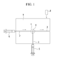
- FIG. 1 is a schematic diagram showing an apparatus for manufacturing encapsulated liquid crystals according to a first exemplary embodiment
- FIG. 2 is an enlarged view of a portion I in FIG. 1 ;
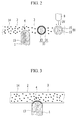
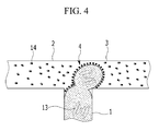
- FIGS. 3 and 4 are diagrams sequentially illustrating a method of manufacturing encapsulated liquid crystals using the apparatus for manufacturing encapsulated liquid crystals according to the first exemplary embodiment
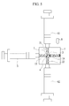
- FIG. 5 is a schematic diagram showing an apparatus for manufacturing encapsulated liquid crystals according to a second exemplary embodiment
- FIG. 6 is a cross-sectional view of a liquid crystal display (LCD) according to a first exemplary embodiment
- FIG. 7 is a cross-sectional view of a liquid crystal display (LCD) according to a second exemplary embodiment
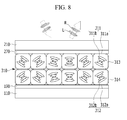
- FIG. 8 is a cross-sectional view of a liquid crystal display (LCD) according to a third exemplary embodiment
- FIG. 9 is a cross-sectional view of a liquid crystal display (LCD) according to a fourth exemplary embodiment
- FIG. 10 is a cross-sectional view of a liquid crystal display (LCD) according to a fifth exemplary embodiment.
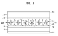
- FIG. 11 is a cross-sectional view of a liquid crystal display (LCD) according to a sixth exemplary embodiment.
- LCD liquid crystal display
- constituent elements having the same configuration are representatively described in a first exemplary embodiment by using the same reference numeral and only constituent elements other than the constituent elements described in the first exemplary embodiment will be described in other embodiments.
- FIGS. 1 and 2 An apparatus for manufacturing encapsulated liquid crystals according to a first exemplary embodiment is described in detail below with reference to FIGS. 1 and 2 .
- FIG. 1 is a schematic diagram showing the apparatus for manufacturing encapsulated liquid crystals according to the first exemplary embodiment
- FIG. 2 is an enlarged view of a portion I in FIG. 1 .
- the apparatus for manufacturing encapsulated liquid crystals according to the first exemplary embodiment may include a first flow duct 1 configured to have liquid crystals 13 flow there through, a second flow duct 2 configured to have encapsulation film materials 14 flow there through, and a third flow duct 3 configured to have an inflow portion coupled to the outflow portion of the first flow duct 1 and to the outflow portion of the second flow duct 2.
- the liquid crystals 13 may be cholesteric liquid crystals or nematic liquid crystals.
- the encapsulation film materials 14 may be a silica-based or fluorine-based UV-curable surface active agent or a different kind of a curable surface active agent. Furthermore, the encapsulation film materials 14 may be a water-soluble polymer material, such as deionized gelatine, polyvinyl alcohol, and latex.
- the first to third flow ducts 1, 2, and 3 may have a pipe pattern formed in a frame T made of polydimethylsiloxane (PDMS), silicon, or glass.
- PDMS polydimethylsiloxane
- the diameter of each of the first to third flow ducts 1, 2, and 3 may be measured in micrometer(s) ( ⁇ m).
- a first injector 5 for injecting the liquid crystals 13 into the first flow duct 1 may be connected to the inflow portion of the first flow duct 1
- a second injector 6 for injecting the encapsulation film materials 14 into the second flow duct 2 may be connected to the inflow portion of the second flow duct 2.
- the first injector 5 controls the flux and flow rate of the liquid crystals 13, flowing through the first flow duct 1, by controlling the pressure of the liquid crystals 13.
- the second injector 6 controls the flux and flow rate of the encapsulation film materials 14, flowing through the second flow duct 2, by controlling the pressure of the encapsulation film materials 14.
- a liquid crystal droplet generator 4 may be formed at a portion where the outflow portion of the first flow duct 1, the outflow portion of the second flow duct 2, and the inflow portion of the third flow duct 3 meet.
- the second flow duct 2 and the third flow duct 3 may be placed on the same straight line.
- the first flow duct 1 may be orthogonal to the second flow duct 2 and the third flow duct 3 at the liquid crystal droplet generator 4, and the locations of the first flow duct 1 and the second flow duct 2 may be exchanged.
- the liquid crystal droplet generator 4 produces liquid crystal droplets 10 by mixing the liquid crystals 13 and the encapsulation film materials 14.
- the liquid crystals 13 and the encapsulation film materials 14 are injected into the first flow duct 1 and the second flow duct 2 of approximately a micrometer in size, the liquid crystals 13 and the encapsulation film materials 14 are mixed in the liquid crystal droplet generator 4 where the first flow duct 1 and the second flow duct 2 meet by means of hydrodynamic instability, thus producing the liquid crystal droplets 10.
- the encapsulation film material 14 surrounds the liquid crystals 13 by means of a self-assembly effect.
- a curing machine 8 for curing the liquid crystal droplets 10 is spaced apart from the first to third flow ducts 1, 2, and 3.
- the curing machine 8 radiates ultraviolet light (UV) onto the liquid crystal droplets 10 to cure the encapsulation film materials 14 of the liquid crystal droplets 10 into encapsulation films 15, thereby making the liquid crystal droplets 10 into the encapsulated liquid crystals 30.
- UV ultraviolet light
- the size of the liquid crystal droplet 10 or the encapsulated liquid crystal 30 may be controlled by adjusting surface tension, viscosity, the flux, and the flow rate (or flow pressure) of the liquid crystals 13 and the encapsulation film materials 14.
- the diameter of the encapsulated liquid crystal 30 flowing through the third flow duct 3 may be in micrometer ( ⁇ m) units.
- the diameter of the encapsulated liquid crystal 30 may be 10 nm to 100 ⁇ m
- the plurality of encapsulated liquid crystals 30 manufactured using the apparatus for manufacturing encapsulated liquid crystals has a uniform size, and the encapsulated liquid crystals 30 may have a diameter within a deviation of ⁇ 6.5%.
- an encapsulated liquid crystal having a maximum diameter, from among manufactured encapsulated liquid crystals, is 4.62 ⁇ m in diameter
- an encapsulated liquid crystal having a minimum diameter, from among the manufactured encapsulated liquid crystals is 1.68 ⁇ m in diameter
- the manufactured encapsulated liquid crystals have an average diameter of 2.67 ⁇ m.
- the encapsulated liquid crystals have a large deviation of ⁇ 50% or higher on the basis of the diameter of the encapsulated liquid crystal having the average value.
- a liquid crystal display (LCD) using the encapsulated liquid crystals of a non-uniform size has a different electro-optical characteristic according to the size of the encapsulated liquid crystals. Furthermore, since the size of the encapsulated liquid crystals is non-uniform, scattering is generated owing to a difference in the refractive index between liquid crystals and an encapsulation film forming the encapsulated liquid crystals, thereby deteriorating an optical characteristic.
- the encapsulated liquid crystals 30 were manufactured using the apparatus for manufacturing encapsulated liquid crystals according to the first exemplary embodiment, when the flow rate of the liquid crystals 13 was 37 ⁇ l/min and the flow rate of the encapsulation film materials 14 was 5000 ⁇ l/min, a maximum diameter of the manufactured encapsulated liquid crystals 30 was 56.1 ⁇ m, a minimum diameter of the manufactured encapsulated liquid crystals 30 was 49.4 ⁇ m, and the manufactured encapsulated liquid crystals 30 had an average diameter of 52.9 ⁇ m. It can be seen that the encapsulated liquid crystals 30 have a uniform diameter within a deviation of ⁇ 6.5% on the basis of the average diameter of the encapsulated liquid crystals 30.
- liquid crystal display having a liquid crystal layer including the encapsulated liquid crystals 30 of a uniform size
- a screen distortion phenomenon resulting from external pressure such as brushing or pooling
- FIGS. 3 and 4 are diagrams sequentially illustrating the method of manufacturing the encapsulated liquid crystals using the apparatus for manufacturing encapsulated liquid crystals according to the first exemplary embodiment.
- the liquid crystals 13 may be injected into the first flow duct 1 using the first injector 5, and the encapsulation film materials 14 may be injected into the second flow duct 2 using the second injector 6.
- the encapsulation film materials 14 coming in contact with the liquid crystals 13 in the liquid crystal droplet generator 4 are adhered to surfaces of the liquid crystals 13.
- the liquid crystals 13 and the encapsulation film materials 14 flown into the liquid crystal droplet generator 4 are mixed together. That is, the encapsulation film materials 14 coming into contact with the liquid crystals 13 in the liquid crystal droplet generator 4 are adhered to the surfaces of the liquid crystals 13, thus surrounding the liquid crystals 13. At this time, the liquid crystals 13 are separated from each other in a droplet form by means of the flow pressure of the encapsulation film materials 14.
- the encapsulation film materials 14 surround the liquid crystals 13 of a droplet form by means of a self-assembly effect, thereby forming the liquid crystal droplets 10.
- UV ultraviolet light
- UV light may be radiated to the liquid crystal droplets 10, thus making the liquid crystal droplets 10 into the encapsulated liquid crystals 30.
- the size of the encapsulated liquid crystals 30 may be controlled by adjusting surface tension, viscosity, the flux, and the flow rate (or flow pressure) of the liquid crystals 13 and the encapsulation film materials 14.
- a plurality of the encapsulated liquid crystals 30 can be fabricated by repeating the above manufacturing process, and the encapsulated liquid crystals 30 of a uniform size can be fabricated.
- Each of the encapsulated liquid crystals 30 may have a diameter within a deviation of ⁇ 6.5%.
- liquid crystal display By manufacturing a liquid crystal display (LCD) having a liquid crystal layer including the encapsulated liquid crystals 30 of a uniform size as described above, a screen distortion phenomenon resulting from external pressure can be prevented.
- LCD liquid crystal display
- the second flow duct 2 through which the encapsulation film materials 14 flow and the third flow duct 3 through which the encapsulated liquid crystals 30 flow are illustrated to be placed on the same straight line, and the first flow duct 1 through which the liquid crystals 13 flow is illustrated to be orthogonal to the second flow duct 2 and the third flow duct 3 in the liquid crystal droplet generator 4.
- the first to third flow ducts 1, 2, and 3 may be disposed in various positions in order to optimize the size and manufacturing conditions of the encapsulated liquid crystals 30.
- FIG. 5 is a schematic diagram showing the apparatus for manufacturing encapsulated liquid crystals according to the second exemplary embodiment.
- the second exemplary embodiment is substantially equivalent to the first exemplary embodiment of FIGS. 1 and 2 except only the locations where a first flow duct to a third flow duct are disposed, and a description of overlapping portions is omitted for simplicity.
- the apparatus for manufacturing encapsulated liquid crystals includes a first flow duct 1 configured to have liquid crystals 13 flow there through, a second flow duct 2 configured to have encapsulation film materials 14 flow there through, and a third flow duct 3 configured to have an inflow portion connected to the outflow portion of the first flow duct 1 and the outflow portion of the second flow duct 2.
- the first flow duct 1 and the third flow duct 3 are placed on the same straight line.
- the second flow duct 2 includes a second upper flow duct 21 and a second lower flow duct 22 which meet at a liquid crystal droplet generator 4.
- the second upper flow duct 21 and the second lower flow duct 22 are orthogonal to the first flow duct 1 and the third flow duct 3 at the liquid crystal droplet generator 4.
- a first injector 5 for injecting the liquid crystals 13 into the first flow duct 1 is connected to the inflow portion of the first flow duct 1.
- a second upper injector 61 for injecting the encapsulation film materials 14 into the second upper flow duct 21 is connected to the inflow portion of the second upper flow duct 21.
- a second lower injector 62 for injecting the encapsulation film materials 14 into the second lower flow duct 22 may be connected to the inflow portion of the second lower flow duct 22.
- the liquid crystals 13 flowing through the first flow duct 1 are mixed with the encapsulation film materials 14, flowing through the second upper flow duct 21 and the second lower flow duct 22, in the liquid crystal droplet generator 4. At this time, the liquid crystals 13 are separated from each other in a droplet form by means of the flow pressure of the encapsulation film materials 14 flowing from the upper and lower sides to the liquid crystal droplet generator 4.
- the encapsulation film materials 14 surround the liquid crystals 13 of a droplet form by means of a self-assembly effect, thereby forming liquid crystal droplets 10.
- a curing machine 8 radiates ultraviolet light (UV) to the liquid crystal droplets 10, thus curing the encapsulation film materials 14 of the liquid crystal droplets 10 into encapsulation films 15. Accordingly, the liquid crystal droplets 10 are made into the encapsulated liquid crystals 30.
- the encapsulated liquid crystals 30 flow along the third flow duct 3.
- the curing machine 8 may radiate ultraviolet light (UV) to the liquid crystal droplets 10, thereby making the liquid crystal droplets 10 into the encapsulated liquid crystals 30.
- UV ultraviolet light
- a plurality of the encapsulated liquid crystals of a uniform size can be fabricated by repeating the above manufacturing process.
- a liquid crystal display including the encapsulated liquid crystals fabricated using the apparatus and method for manufacturing encapsulated liquid crystals according to the first and second exemplary embodiments is described in detail below with reference to FIG. 6 .
- FIG. 6 is a cross-sectional view of a liquid crystal display (LCD) according to a first exemplary embodiment.
- LCD liquid crystal display
- the liquid crystal display (LCD) includes a first substrate 110 and a second substrate 210 configured to face each other and a cholesteric liquid crystal layer 310 disposed between the two substrates 110 and 210.
- a first electrode 190 may be formed on the first substrate 110 and a second electrode 270 may be formed on the second substrate 210, so that an electric field can be formed between the first electrode 190 and the second electrode 270.
- Spacers may be disposed between the first substrate 110 and the second substrate 210 in order to control the thickness of the cholesteric liquid crystal layer 310.
- the first substrate 110 and the second substrate 210 may be formed of insulation substrates, such as transparent glass or plastic.
- a plurality of cholesteric encapsulation liquid crystals 31 having a uniform size is dispersed in the cholesteric liquid crystal layer 310.
- Each of the cholesteric encapsulation liquid crystals 31 includes cholesteric liquid crystals 31b placed within each of cholesteric encapsulation films 31a.
- the cholesteric liquid crystal 31b may have a helical pitch which reflects a visible ray having a wavelength of 380 nm to 770 nm.
- the cholesteric encapsulation film 31a may have a thickness of 1 nm to 10 ⁇ m. If the thickness of the cholesteric encapsulation film 31a is too small, the cholesteric encapsulation liquid crystals 31 are likely to be broken.
- the thickness of the cholesteric encapsulation film 31a may vary according to the physical properties of a material of the cholesteric encapsulation film 31a.
- the size of the plurality of cholesteric encapsulation liquid crystals 31 may range from 10 nm to 100 ⁇ m.
- the cholesteric encapsulation liquid crystals 31 are uniform and each may have a diameter within a deviation of ⁇ 6.5%.
- the cholesteric liquid crystal layer 310 has two stable states of a planar state and a focal conic state and can maintain the two stable states although external voltage is not supplied.
- the cholesteric liquid crystals 31b In the planar state, the cholesteric liquid crystals 31b have a helical structure and reflect light of a specific wavelength along the helical pitch.
- the focal conic state the cholesteric liquid crystals 31b have their helical axes arranged in a horizontal direction to the first electrode 190 and the second electrode 270 and transmit light.
- the cholesteric liquid crystal layer 310 including the cholesteric encapsulation liquid crystals 31 is formed as described above, a color shift according to the viewing angle can be minimized and a screen distortion phenomenon, occurring when a liquid crystal display (LCD) is bent or when pressure is applied to the surface of a liquid crystal display (LCD), can be minimized. Accordingly, the bistability of the cholesteric liquid crystal layer 310 can be maintained.
- cholesteric liquid crystal layer 310 including the cholesteric encapsulation liquid crystals 31 of a uniform size is formed, a screen distortion phenomenon resulting from external pressure can be prevented. Accordingly, a liquid crystal display (LCD) having a constant electro-optical characteristic and an excellent optical characteristic can be fabricated.
- LCD liquid crystal display
- the first electrode 190 and the second electrode 270 are illustrated to be formed in order to apply a vertical electric field. However, both the first electrode 190 and the second electrode 270 may be formed over the first substrate 110 in order to apply a horizontal electric field, or three or more electrodes may be formed in order to apply both the vertical electric field and the horizontal electric field.
- red reflection cholesteric liquid crystals, green reflection cholesteric liquid crystals, and blue reflection cholesteric liquid crystals for reflecting a red light, a green light, and a blue light, respectively, may be formed of the cholesteric encapsulation liquid crystals 31 having a uniform size. In this case, color can be implemented while a screen distortion phenomenon resulting from external pressure is prevented.
- the cholesteric encapsulation liquid crystals 31 of the cholesteric liquid crystal layer 310 may be left-handed or right-handed.
- the cholesteric liquid crystal layer 310 in which left-handed cholesteric encapsulation liquid crystals and right-handed cholesteric encapsulation liquid crystals 312 are mixed is possible.
- LCD liquid crystal display
- FIG. 7 is a cross-sectional view of the liquid crystal display (LCD) according to the second exemplary embodiment.
- the second exemplary embodiment is substantially equivalent to the first exemplary embodiment of FIG. 6 except that the cholesteric liquid crystal layer 310 includes both left-handed cholesteric encapsulation liquid crystals and right-handed cholesteric encapsulation liquid crystals, and a description of overlapping portions is omitted for simplicity.
- a plurality of left-handed cholesteric encapsulation liquid crystals 311 and a plurality of right-handed cholesteric encapsulation liquid crystals 312 of a uniform size are dispersed in a cholesteric liquid crystal layer 310.
- the left-handed cholesteric encapsulation liquid crystals 311 and the right-handed cholesteric encapsulation liquid crystals 312 have a uniform size and each may have a diameter within a deviation of ⁇ 6.5%. Accordingly, a liquid crystal display (LCD) having a constant electro-optical characteristic and an excellent optical characteristic can be fabricated because a screen distortion phenomenon resulting from external pressure can be prevented.
- LCD liquid crystal display
- the left-handed cholesteric encapsulation liquid crystals 311 include left-handed cholesteric liquid crystals 311b within each of left-handed cholesteric encapsulation films 311a.
- Each of the right-handed cholesteric encapsulation liquid crystals 312 includes right-handed cholesteric liquid crystals 312b within each of right-handed cholesteric encapsulation film 312a.
- the left-handed cholesteric liquid crystals 311b reflect a left-handed circular polarized light L
- the right-handed cholesteric liquid crystals 312b reflects a right-handed circular polarized light R.
- the liquid crystal display (LCD) of the first exemplary embodiment only one of the left-handed cholesteric encapsulation liquid crystals 311 and the right-handed cholesteric encapsulation liquid crystals 312 are included in the cholesteric liquid crystal layer 310. Accordingly, the reflectivity of the cholesteric liquid crystal layer 310 may not exceed a maximum of 50%. In the liquid crystal display (LCD) according to the second exemplary embodiment, however, the left-handed cholesteric encapsulation liquid crystals 311 and the right-handed cholesteric encapsulation liquid crystals 312 are mixed in the cholesteric liquid crystal layer 310 and thus the reflectivity of the cholesteric liquid crystal layer 310 may be maximized.
- the left-handed cholesteric encapsulation liquid crystals 311 and the right-handed cholesteric encapsulation liquid crystals 312 are randomly mixed to form the cholesteric liquid crystal layer 310.
- the left-handed cholesteric encapsulation liquid crystals 311 and the right-handed cholesteric encapsulation liquid crystals 312 may have a layered structure.
- LCD liquid crystal display
- FIG. 8 is a cross-sectional view of the liquid crystal display (LCD) according to the third exemplary embodiment.
- the third exemplary embodiment is substantially equivalent to the second exemplary embodiment of FIG. 7 except that the left-handed cholesteric encapsulation liquid crystals 311 and the right-handed cholesteric encapsulation liquid crystals 312 of a cholesteric liquid crystal layer 310 have a layered structure, and a description of overlapping portions is omitted for simplicity.
- the cholesteric liquid crystal layer 310 includes a left-handed cholesteric liquid crystal encapsulation layer 313 and a right-handed cholestric liquid crystal encapsulation layer 314 formed on the left-handed cholestric liquid crystal encapsulation layer 313.
- the left-handed cholestric liquid crystal encapsulation layer 313 includes a plurality of left-handed cholesteric encapsulation liquid crystals 311 having a uniform size.
- the right-handed cholestric liquid crystal encapsulation layer 314 includes a plurality of right-handed cholesteric encapsulation liquid crystals 312 having a uniform size.
- the left-handed cholesteric encapsulation liquid crystals 311 and the right-handed cholesteric encapsulation liquid crystals 312 have a uniform size and each may have a diameter within a deviation of ⁇ 6.5%. Accordingly, since a screen distortion phenomenon resulting from external pressure can be prevented, a liquid crystal display (LCD) having a constant electro-optical characteristic and an excellent optical characteristic can be fabricated.
- LCD liquid crystal display
- the cholesteric liquid crystal layer 310 is formed of the left-handed cholestric liquid crystal encapsulation layer 313 for reflecting a left-handed circular polarized light L and the right-handed cholestric liquid crystal encapsulation layer 314 for reflecting a right-handed circular polarized light R, both the left-handed circular polarized light L and the right-handed circular polarized light R can be reflected. Accordingly, the reflectivity of the cholesteric liquid crystal layer 310 may be maximized.
- the liquid crystal display (LCD) of the first exemplary embodiment is illustrated to include the cholesteric liquid crystal layer 310 including the cholesteric encapsulation liquid crystals, but may include a nematic liquid crystal layer including nematic encapsulation liquid crystals.
- LCD liquid crystal display
- FIG. 9 is a cross-sectional view of the liquid crystal display (LCD) according to the fourth exemplary embodiment.
- the fourth exemplary embodiment is substantially equivalent to the third exemplary embodiment of FIG. 8 except that a nematic liquid crystal layer is formed, and a description of overlapping portions is omitted for simplicity.
- the liquid crystal display (LCD) includes a first substrate 110 and a second substrate 210 configured to face each other and a nematic liquid crystal layer 320 disposed between the two substrates 110 and 210.
- a first electrode 190 may be formed on the first substrate 110
- a second electrode 270 may be formed on the second substrate 210.
- an electric field can be formed between the first electrode 190 and the second electrode 270.
- a first polarizing plate 111 and a second polarizing plate 211 are formed under the first substrate 110 and over the second substrate 210, respectively.
- the transmission axes of the first polarizing plate 111 and the second polarizing plate 211 may be vertical to each other or may have a specific angle.
- a phase delay film may be further formed in the first polarizing plate 111 and the second polarizing plate 211 in order to improve the viewing angle.
- a plurality of nematic encapsulation liquid crystals 32 having a uniform size is dispersed in the nematic liquid crystal layer 320.
- the nematic encapsulation liquid crystals 32 include nematic liquid crystals 32b within each of nematic encapsulation films 32a.
- the size of the nematic encapsulation liquid crystals 32 may have a deviation of ⁇ 6.5% in diameter. Accordingly, a liquid crystal display (LCD) having a constant electro-optical characteristic and an excellent optical characteristic can be fabricated because a screen distortion phenomenon resulting from external pressure is prevented.
- LCD liquid crystal display
- the nematic liquid crystals 32b may include twisted nematic (TN) liquid crystals, horizontally arranged nematic liquid crystals, axis-symmetrically arranged nematic liquid crystals, etc. and may be positive dielectric constant anisotropic liquid crystals or negative dielectric constant anisotropic liquid crystals.
- TN liquid crystals are shown in FIG. 9 .
- first electrode 190 and the second electrode 270 are illustrated to be formed in order to supply a vertical electric field. However, both the first electrode 190 and the second electrode 270 may be formed over the first substrate in order to supply a horizontal electric field, or three or more electrodes may be formed in order to supply both the vertical electric field and the horizontal electric field.
- an opening pattern for forming multiple domains may be formed in the first electrode or the second electrode in order to minimize a color shift according to the viewing angle.
- a rise of a driving voltage resulting from the encapsulation film can be minimized by adding nanoparticles to the nematic liquid crystal layer of the liquid crystal display (LCD) according to the fourth exemplary embodiment.
- LCD liquid crystal display
- FIG. 10 is a cross-sectional view of the liquid crystal display (LCD) according to the fifth exemplary embodiment.
- the fifth exemplary embodiment is substantially equivalent to the fourth exemplary embodiment of FIG. 9 except that nanoparticles are added to a nematic liquid crystal layer, and a description of overlapping portions is omitted for simplicity.
- the liquid crystal display (LCD) includes a first substrate 110 and a second substrate 210 configured to face each other and a nematic liquid crystal layer 320 disposed between the two substrates 110 and 210.
- a plurality of nematic encapsulation liquid crystals 32 having a uniform size is dispersed in the nematic liquid crystal layer 320.
- a plurality of nanoparticles 40 is dispersed between the nematic encapsulation liquid crystals 32.
- each of the nanoparticles 40 may be 10 nm to 1 ⁇ m, and the nanoparticles 40 may be any one selected from among gold, silver, carbon nanotube, and ferroelectric materials.
- the nematic encapsulation liquid crystals 32 include nematic liquid crystals 32b within each of encapsulation films 32a. Horizontally oriented nematic liquid crystals are shown in FIG. 10 .
- the plurality of nematic encapsulation liquid crystals 32 has a uniform size and each may have a diameter within a deviation of ⁇ 6.5%. Accordingly, a liquid crystal display (LCD) having a constant electro-optical characteristic and an excellent optical characteristic can be fabricated because a screen distortion phenomenon resulting from external pressure is prevented.
- LCD liquid crystal display
- Equation 1 An equation relating to the dielectric constant of a mixture of the nematic encapsulation film 32a and the nanoparticles 40 is written in Equation 1.
- ⁇ m is the dielectric constant of the mixture of the nematic encapsulation film 32a and the nanoparticles 40
- ⁇ 1 is the dielectric constant of the encapsulation film 32a
- ⁇ 2 is the dielectric constant of the nanoparticles 40
- B 1 is the volume of the nematic encapsulation film 32a
- B 2 is the volume of the nanoparticles 40.
- the dielectric constant ⁇ 1 of the encapsulation film 32a is different from the dielectric constant ⁇ 2 of the nanoparticles 40.
- the dielectric constant ⁇ m of the mixture of the nematic encapsulation film 32a and the nanoparticles 40 can be raised.
- the nematic encapsulation films 32a may function to prevent the generation of a voltage drop and thus prevent a driving voltage from rising.
- the nanoparticles 40 are illustrated to be dispersed in the nematic liquid crystal layer 320.
- the nanoparticles 40 may be dispersed in the cholesteric liquid crystal layer 310 of the previous embodiments.
- the nematic encapsulation liquid crystals 32 and the nanoparticles 40 are illustrated to be separated from each other and dispersed in the nematic liquid crystal layer 320.
- the nanoparticles 40 may come in contact with the nematic encapsulation liquid crystals 32.
- LCD liquid crystal display
- FIG. 11 is a cross-sectional view of the liquid crystal display (LCD) according to the sixth exemplary embodiment.
- the sixth exemplary embodiment is substantially equivalent to the fifth exemplary embodiment of FIG. 10 except that the plurality of nematic encapsulation liquid crystals is formed of a single layer and the nanoparticles 40 come in contact with the nematic encapsulation liquid crystals 32, and a description of overlapping portions is omitted for simplicity.
- the liquid crystal display (LCD) may include a first substrate 110 and a second substrate 210 configured to face each other and a nematic liquid crystal layer 320 disposed between the two substrates 110 and 210.
- a plurality of nematic encapsulation liquid crystals 32 having a uniform size comes in contact with each other in the nematic liquid crystal layer 320.
- the nematic encapsulation liquid crystals 32 include nematic liquid crystals 32b within each of nematic encapsulation films 32a. TN liquid crystals are shown in FIG. 11 .
- the plurality of nematic encapsulation liquid crystals 32 has a uniform size and each may have a diameter within a deviation of ⁇ 6.5%. Accordingly, a liquid crystal display (LCD) having a constant electro-optical characteristic and an excellent optical characteristic can be fabricated because a screen distortion phenomenon resulting from external pressure is prevented.
- LCD liquid crystal display
- the nematic encapsulation films 32a may function to prevent the generation of a voltage drop and thus prevent a driving voltage from rising.
Landscapes
- Chemical & Material Sciences (AREA)
- Physics & Mathematics (AREA)
- Organic Chemistry (AREA)
- Crystallography & Structural Chemistry (AREA)
- Nonlinear Science (AREA)
- Dispersion Chemistry (AREA)
- Materials Engineering (AREA)
- Mathematical Physics (AREA)
- Engineering & Computer Science (AREA)
- General Physics & Mathematics (AREA)
- Optics & Photonics (AREA)
- Chemical Kinetics & Catalysis (AREA)
- Liquid Crystal (AREA)
- Processing And Handling Of Plastics And Other Materials For Molding In General (AREA)
Abstract
Description
- The general inventive concept relates to an apparatus and method for manufacturing encapsulated liquid crystals and a liquid crystal display (LCD) including the encapsulated liquid crystals.
- Liquid crystal display (LCD) devices are being focused on as flat panel display devices that may resolve problems seen in cathode ray tube (CRT) display apparatuses due to smaller size, lighter weight, smaller thickness, and lower power consumption. Generally, an LCD device is a display device that can change arrangements of liquid crystal molecules, which have material properties between those of liquids and those of solids, in liquid crystal cells by applying an external electric field to change optical properties including double refraction, circumpolarization, and light diffusion properties of the liquid crystal cells. Recently, for miniaturization of an LCD device, continuous research is being performed on components constituting an LCD device, e.g., a backlight, a connector, a printed circuit board (PCB), and a combination structure.
- A liquid crystal display (LCD) includes two sheets of substrates having electrodes formed therein and a liquid crystal layer inserted between the substrates and controls the amount of light passing therethrough by rearranging the liquid crystal molecules of the liquid crystal layer by supplying voltage to the electrodes.
- In the case where the liquid crystal layer of the liquid crystal display (LCD) is formed of a plurality of encapsulated liquid crystals, a screen distortion phenomenon, occurring when the liquid crystal display (LCD) is bent or when pressure is applied to a surface of the liquid crystal display (LCD), can be minimized.
- The encapsulated liquid crystals are chiefly manufactured by stirring liquid crystals and an encapsulation film material using a stirrer. In this case, it is difficult to uniformly implement the size of the encapsulated liquid crystals. A liquid crystal display (LCD) using encapsulated liquid crystals of a non-uniform size has a different electro-optical characteristic according to the size of the encapsulated liquid crystals. Since the size of the encapsulated liquid crystals is non-uniform, scattering is generated because of a difference in the refractive index between the liquid crystals and the encapsulation film forming the encapsulated liquid crystals, thereby deteriorating an optical characteristic.
- The above information disclosed in this Related Art section is only for enhancement of understanding of the background of the described technology and therefore it may contain information that does not form the prior art that is already known in this country to a person of ordinary skill in the art.
- The described technology has been made in an effort to provide an apparatus and method for manufacturing encapsulated liquid crystals and a liquid crystal display (LCD) including the encapsulated liquid crystals, having an advantage in that the encapsulated liquid crystals of a uniform size can be manufactured.
- An apparatus for manufacturing encapsulated liquid crystals according to an exemplary embodiment may include at least one first flow duct configured to have liquid crystals flow there through, at least one second flow duct configured to have encapsulation film materials flow there through, a third flow duct configured to have an inflow portion connected to an outflow portion of the first flow duct and an outflow portion of the second flow duct and to have liquid crystal droplets in which the liquid crystals and the encapsulation film materials are mixed flow there through, and a curing machine configured to manufacture the encapsulated liquid crystals by curing the liquid crystal droplets.
- A liquid crystal droplet generator may be located where the outflow portion of the first flow duct, the outflow portion of the second flow duct, and the inflow portion of the third flow duct are met and it may manufacture the liquid crystal droplets by mixing the liquid crystals and the encapsulation film materials.
- The apparatus may further include a first injector for injecting the liquid crystals into the first flow duct and a second injector for injecting the encapsulation film materials into the second flow duct.
- The flux and flow rate of the liquid crystals flowing through the first flow duct may be controlled by adjusting the pressure of the first injector, and the flux and flow rate of the encapsulation film materials flowing through the second flow duct may be controlled by adjusting the pressure of the second injector.
- The encapsulation film materials may include a silica-based or fluorine-based UV-curable surface active agent or any one selected from among different kinds of curable surface active agents.
- The encapsulation film materials may include any one selected from among deionized gelatine, polyvinyl alcohol, and latex.
- The diameter of the first flow duct to the third flow duct may be a micrometer unit. Preferably, the diameter of the first flow duct to the third flow duct ranges from 1µm to 100 µm, more preferably from 10µm to 100µm.
- The second flow duct and the third flow duct may be placed on the same straight line, and the first flow duct may be orthogonal to the second flow duct and the third flow duct at the liquid crystal droplet generator.
- The first flow duct and the third flow duct may be placed on the same straight line, and the second flow duct may be orthogonal to the first flow duct and the third flow duct at the liquid crystal droplet generator.
- The first flow duct and the third flow duct may be placed on the same straight line, the second flow duct may be orthogonal to the first flow duct and the third flow duct at the liquid crystal droplet generator, and the second flow duct may include a second upper flow duct and a second lower flow duct which are met at the liquid crystal droplet generator.
- Furthermore, a method of manufacturing encapsulated liquid crystals according to an exemplary embodiment may include injecting liquid crystals into a first flow duct using a first injector, injecting encapsulation film materials into a second flow duct using a second injector, producing liquid crystal droplets in which the liquid crystals and the encapsulation film materials are mixed at a liquid crystal droplet generator where an outflow portion of the first flow duct, an outflow portion of the second flow duct, and an inflow portion of the third flow duct are met, and manufacturing the encapsulated liquid crystals by curing the liquid crystal droplets.
- The encapsulated liquid crystals may be manufactured by curing the encapsulation film materials of the liquid crystal droplets flowing through the third flow duct.
- The encapsulated liquid crystals may be manufactured by curing the encapsulation film materials of the liquid crystal droplets drained from the third flow duct.
- The flux and flow rate of the liquid crystals flowing through the first flow duct may be controlled by adjusting the pressure of the first injector, and the flux and flow rate of the encapsulation film materials flowing through the second flow duct may be controlled by adjusting the pressure of the second injector.
- The encapsulation film materials may include any one selected from among a silica-based or fluorine-based UV-curable surface active agent, different kinds of curable surface active agents, deionized gelatine, polyvinyl alcohol, and latex.
- Furthermore, a liquid crystal display (LCD) according to an exemplary embodiment may include a first substrate, a first electrode formed on the first substrate, a second substrate configured to face the first substrate, a second electrode formed on the second substrate, and a liquid crystal layer formed between the first electrode and the second electrode and configured to include a plurality of encapsulated liquid crystals, including liquid crystals and encapsulation films each surrounding the liquid crystals. The diameter of the plurality of encapsulated liquid crystals may have a deviation of ±6.5%.
- The encapsulated liquid crystals may include cholesteric encapsulation liquid crystals, including cholesteric liquid crystals and cholesteric encapsulation films each surrounding the cholesteric liquid crystals.
- The encapsulated liquid crystals may include left-handed cholesteric encapsulation liquid crystals, including left-handed cholesteric liquid crystals and left-handed cholesteric encapsulation films each surrounding the left-handed cholesteric liquid crystals, and right-handed cholesteric encapsulation liquid crystals, including right-handed cholesteric liquid crystals and right-handed cholesteric encapsulation films each surrounding the right-handed cholesteric liquid crystals.
- The left-handed cholesteric encapsulation liquid crystals may form a left-handed cholestric liquid crystal encapsulation layer, and the right-handed cholesteric encapsulation liquid crystals may form a right-handed cholestric liquid crystal encapsulation layer.
- The encapsulated liquid crystals may include nematic encapsulation liquid crystals, including nematic liquid crystals and nematic encapsulation films each surrounding the nematic liquid crystals.
- The encapsulated liquid crystals may be dispersed.
- The encapsulated liquid crystals may form at least one layer.
- The liquid crystal display may further include nanoparticles dispersed between the encapsulated liquid crystals, and the nanoparticles may have a different dielectric constant from the encapsulation film.
- The encapsulated liquid crystals may have a diameter of 10 nm to 100 µm, preferably of 100nm to 100µm, more preferably of 1µm to 100µm, even more preferably of 40µm to 60µm. The encapsulation film may have a thickness of 1 nm to 10 µm, preferably of 5nm to 1µm, more preferably of 10nm to 100nm.
- According to the present invention, encapsulated liquid crystals of a uniform size can be manufactured by introducing liquid crystals and an encapsulation film material into the first flow duct and the second flow duct, respectively, and controlling the flux, the flow rate, etc. of the liquid crystals and the encapsulation film material.
- Furthermore, since a liquid crystal layer including the encapsulated liquid crystals of a uniform size is formed, a liquid crystal display (LCD) having a constant electro-optical characteristic and an excellent optical characteristic can be manufactured.
- A more complete appreciation of the invention, and many of the attendant advantages thereof, will be readily apparent as the same becomes better understood by reference to the following detailed description when considered in conjunction with the accompanying drawings in which like reference symbols indicate the same or similar components, wherein:
-
FIG. 1 is a schematic diagram showing an apparatus for manufacturing encapsulated liquid crystals according to a first exemplary embodiment; -
FIG. 2 is an enlarged view of a portion I inFIG. 1 ; -
FIGS. 3 and4 are diagrams sequentially illustrating a method of manufacturing encapsulated liquid crystals using the apparatus for manufacturing encapsulated liquid crystals according to the first exemplary embodiment; -
FIG. 5 is a schematic diagram showing an apparatus for manufacturing encapsulated liquid crystals according to a second exemplary embodiment; -
FIG. 6 is a cross-sectional view of a liquid crystal display (LCD) according to a first exemplary embodiment; -
FIG. 7 is a cross-sectional view of a liquid crystal display (LCD) according to a second exemplary embodiment; -
FIG. 8 is a cross-sectional view of a liquid crystal display (LCD) according to a third exemplary embodiment; -
FIG. 9 is a cross-sectional view of a liquid crystal display (LCD) according to a fourth exemplary embodiment; -
FIG. 10 is a cross-sectional view of a liquid crystal display (LCD) according to a fifth exemplary embodiment; and -
FIG. 11 is a cross-sectional view of a liquid crystal display (LCD) according to a sixth exemplary embodiment. - The present invention will be described more fully hereinafter with reference to the accompanying drawings, in which some exemplary embodiments of the invention are shown. As those skilled in the art would realize, the described embodiments may be modified in various different ways, all without departing from the scope of the present invention. The present invention may be implemented in several different forms and is not limited to the exemplary embodiments.
- The size and thickness of each element shown in the drawings is arbitrary, for convenience of description, and the present invention is not limited thereto.
- Like reference numerals designate like elements throughout the specification. It will be understood that when an element such as a layer, film, region, or substrate is referred to as being Aon@ another element, it can be directly on the other element or intervening elements may also be present. Alternatively, when an element is referred to as being Adirectly on@ another element, there are no intervening elements present.
- In order to clarify the present invention, elements extrinsic to the description are omitted from the details of this description, and like reference numerals refer to like elements throughout the specification.
- In several exemplary embodiments, constituent elements having the same configuration are representatively described in a first exemplary embodiment by using the same reference numeral and only constituent elements other than the constituent elements described in the first exemplary embodiment will be described in other embodiments.
- An apparatus for manufacturing encapsulated liquid crystals according to a first exemplary embodiment is described in detail below with reference to
FIGS. 1 and2 . -
FIG. 1 is a schematic diagram showing the apparatus for manufacturing encapsulated liquid crystals according to the first exemplary embodiment, andFIG. 2 is an enlarged view of a portion I inFIG. 1 . - As shown in
FIGS. 1 and2 , the apparatus for manufacturing encapsulated liquid crystals according to the first exemplary embodiment may include afirst flow duct 1 configured to haveliquid crystals 13 flow there through, asecond flow duct 2 configured to haveencapsulation film materials 14 flow there through, and athird flow duct 3 configured to have an inflow portion coupled to the outflow portion of thefirst flow duct 1 and to the outflow portion of thesecond flow duct 2. - The
liquid crystals 13 may be cholesteric liquid crystals or nematic liquid crystals. Theencapsulation film materials 14 may be a silica-based or fluorine-based UV-curable surface active agent or a different kind of a curable surface active agent. Furthermore, theencapsulation film materials 14 may be a water-soluble polymer material, such as deionized gelatine, polyvinyl alcohol, and latex. - The first to
third flow ducts third flow ducts - A first injector 5 for injecting the
liquid crystals 13 into thefirst flow duct 1 may be connected to the inflow portion of thefirst flow duct 1, and a second injector 6 for injecting theencapsulation film materials 14 into thesecond flow duct 2 may be connected to the inflow portion of thesecond flow duct 2. The first injector 5 controls the flux and flow rate of theliquid crystals 13, flowing through thefirst flow duct 1, by controlling the pressure of theliquid crystals 13. The second injector 6 controls the flux and flow rate of theencapsulation film materials 14, flowing through thesecond flow duct 2, by controlling the pressure of theencapsulation film materials 14. - A liquid crystal droplet generator 4 may be formed at a portion where the outflow portion of the
first flow duct 1, the outflow portion of thesecond flow duct 2, and the inflow portion of thethird flow duct 3 meet. Thesecond flow duct 2 and thethird flow duct 3 may be placed on the same straight line. Thefirst flow duct 1 may be orthogonal to thesecond flow duct 2 and thethird flow duct 3 at the liquid crystal droplet generator 4, and the locations of thefirst flow duct 1 and thesecond flow duct 2 may be exchanged. The liquid crystal droplet generator 4 producesliquid crystal droplets 10 by mixing theliquid crystals 13 and theencapsulation film materials 14. - When the
liquid crystals 13 and theencapsulation film materials 14 are injected into thefirst flow duct 1 and thesecond flow duct 2 of approximately a micrometer in size, theliquid crystals 13 and theencapsulation film materials 14 are mixed in the liquid crystal droplet generator 4 where thefirst flow duct 1 and thesecond flow duct 2 meet by means of hydrodynamic instability, thus producing theliquid crystal droplets 10. Theencapsulation film material 14 surrounds theliquid crystals 13 by means of a self-assembly effect. - Furthermore, a curing machine 8 for curing the
liquid crystal droplets 10 is spaced apart from the first tothird flow ducts liquid crystal droplets 10 to cure theencapsulation film materials 14 of theliquid crystal droplets 10 intoencapsulation films 15, thereby making theliquid crystal droplets 10 into the encapsulatedliquid crystals 30. - In this case, the size of the
liquid crystal droplet 10 or the encapsulatedliquid crystal 30 may be controlled by adjusting surface tension, viscosity, the flux, and the flow rate (or flow pressure) of theliquid crystals 13 and theencapsulation film materials 14. - Since the diameter of each of the first to
third flow ducts liquid crystal 30 flowing through thethird flow duct 3 may be in micrometer (µm) units. For example, the diameter of the encapsulatedliquid crystal 30 may be 10 nm to 100 µm - Furthermore, the plurality of encapsulated
liquid crystals 30 manufactured using the apparatus for manufacturing encapsulated liquid crystals has a uniform size, and the encapsulatedliquid crystals 30 may have a diameter within a deviation of ±6.5%. - In the case where encapsulated liquid crystals are manufactured using a conventional apparatus for manufacturing encapsulated liquid crystals using a stirrer, when the amount of liquid crystals is 1 ml, the amount of encapsulation film materials is 100 ml, and the stirrer is rotated at the rate of 500 rpm for one hour, an encapsulated liquid crystal having a maximum diameter, from among manufactured encapsulated liquid crystals, is 4.62 µm in diameter, an encapsulated liquid crystal having a minimum diameter, from among the manufactured encapsulated liquid crystals, is 1.68 µm in diameter, and the manufactured encapsulated liquid crystals have an average diameter of 2.67 µm. Accordingly, the encapsulated liquid crystals have a large deviation of ±50% or higher on the basis of the diameter of the encapsulated liquid crystal having the average value. A liquid crystal display (LCD) using the encapsulated liquid crystals of a non-uniform size has a different electro-optical characteristic according to the size of the encapsulated liquid crystals. Furthermore, since the size of the encapsulated liquid crystals is non-uniform, scattering is generated owing to a difference in the refractive index between liquid crystals and an encapsulation film forming the encapsulated liquid crystals, thereby deteriorating an optical characteristic.
- However, in the case where the encapsulated
liquid crystals 30 were manufactured using the apparatus for manufacturing encapsulated liquid crystals according to the first exemplary embodiment, when the flow rate of theliquid crystals 13 was 37 µl/min and the flow rate of theencapsulation film materials 14 was 5000 µl/min, a maximum diameter of the manufactured encapsulatedliquid crystals 30 was 56.1 µm, a minimum diameter of the manufactured encapsulatedliquid crystals 30 was 49.4 µm, and the manufactured encapsulatedliquid crystals 30 had an average diameter of 52.9 µm. It can be seen that the encapsulatedliquid crystals 30 have a uniform diameter within a deviation of ±6.5% on the basis of the average diameter of the encapsulatedliquid crystals 30. - As described above, when a liquid crystal display (LCD) having a liquid crystal layer including the encapsulated
liquid crystals 30 of a uniform size is fabricated, a screen distortion phenomenon resulting from external pressure, such as brushing or pooling, can be prevented. - A method of manufacturing the encapsulated liquid crystals using the apparatus for manufacturing encapsulated liquid crystals according to the first exemplary embodiment, described above with reference to
FIGS. 1 and2 , is described in detail below with reference toFIGS. 2 to 4 . -
FIGS. 3 and4 are diagrams sequentially illustrating the method of manufacturing the encapsulated liquid crystals using the apparatus for manufacturing encapsulated liquid crystals according to the first exemplary embodiment. - First, as shown in
FIG. 3 , theliquid crystals 13 may be injected into thefirst flow duct 1 using the first injector 5, and theencapsulation film materials 14 may be injected into thesecond flow duct 2 using the second injector 6. Theencapsulation film materials 14 coming in contact with theliquid crystals 13 in the liquid crystal droplet generator 4 are adhered to surfaces of theliquid crystals 13. - Next, as shown in
FIG. 4 , theliquid crystals 13 and theencapsulation film materials 14 flown into the liquid crystal droplet generator 4 are mixed together. That is, theencapsulation film materials 14 coming into contact with theliquid crystals 13 in the liquid crystal droplet generator 4 are adhered to the surfaces of theliquid crystals 13, thus surrounding theliquid crystals 13. At this time, theliquid crystals 13 are separated from each other in a droplet form by means of the flow pressure of theencapsulation film materials 14. - Next, as shown in
FIG. 2 , theencapsulation film materials 14 surround theliquid crystals 13 of a droplet form by means of a self-assembly effect, thereby forming theliquid crystal droplets 10. - Next, ultraviolet light (UV) is radiated onto the
liquid crystal droplets 10, thus curing theencapsulation film materials 14 of theliquid crystal droplets 10 into theencapsulation films 15. Accordingly, theliquid crystal droplets 10 are made into the encapsulatedliquid crystals 30. The encapsulatedliquid crystals 30 flow along thethird flow duct 3. - Alternatively, after the
liquid crystal droplets 10 in which theencapsulation film materials 14 surround theliquid crystals 13 of a droplet form are drained from thethird flow duct 3, ultraviolet light (UV) may be radiated to theliquid crystal droplets 10, thus making theliquid crystal droplets 10 into the encapsulatedliquid crystals 30. In this case, the size of the encapsulatedliquid crystals 30 may be controlled by adjusting surface tension, viscosity, the flux, and the flow rate (or flow pressure) of theliquid crystals 13 and theencapsulation film materials 14. - A plurality of the encapsulated
liquid crystals 30 can be fabricated by repeating the above manufacturing process, and the encapsulatedliquid crystals 30 of a uniform size can be fabricated. Each of the encapsulatedliquid crystals 30 may have a diameter within a deviation of ±6.5%. - By manufacturing a liquid crystal display (LCD) having a liquid crystal layer including the encapsulated
liquid crystals 30 of a uniform size as described above, a screen distortion phenomenon resulting from external pressure can be prevented. - In the first exemplary embodiment, the
second flow duct 2 through which theencapsulation film materials 14 flow and thethird flow duct 3 through which the encapsulatedliquid crystals 30 flow are illustrated to be placed on the same straight line, and thefirst flow duct 1 through which theliquid crystals 13 flow is illustrated to be orthogonal to thesecond flow duct 2 and thethird flow duct 3 in the liquid crystal droplet generator 4. However, the first tothird flow ducts liquid crystals 30. - Hereinafter, an apparatus for manufacturing encapsulated liquid crystals according to a second exemplary embodiment is described in detail with reference to
FIG. 5 . -
FIG. 5 is a schematic diagram showing the apparatus for manufacturing encapsulated liquid crystals according to the second exemplary embodiment. - The second exemplary embodiment is substantially equivalent to the first exemplary embodiment of
FIGS. 1 and2 except only the locations where a first flow duct to a third flow duct are disposed, and a description of overlapping portions is omitted for simplicity. - As shown in
FIG. 5 , the apparatus for manufacturing encapsulated liquid crystals according to the second exemplary embodiment includes afirst flow duct 1 configured to haveliquid crystals 13 flow there through, asecond flow duct 2 configured to haveencapsulation film materials 14 flow there through, and athird flow duct 3 configured to have an inflow portion connected to the outflow portion of thefirst flow duct 1 and the outflow portion of thesecond flow duct 2. Thefirst flow duct 1 and thethird flow duct 3 are placed on the same straight line. Thesecond flow duct 2 includes a secondupper flow duct 21 and a secondlower flow duct 22 which meet at a liquid crystal droplet generator 4. The secondupper flow duct 21 and the secondlower flow duct 22 are orthogonal to thefirst flow duct 1 and thethird flow duct 3 at the liquid crystal droplet generator 4. - A first injector 5 for injecting the
liquid crystals 13 into thefirst flow duct 1 is connected to the inflow portion of thefirst flow duct 1. A secondupper injector 61 for injecting theencapsulation film materials 14 into the secondupper flow duct 21 is connected to the inflow portion of the secondupper flow duct 21. A secondlower injector 62 for injecting theencapsulation film materials 14 into the secondlower flow duct 22 may be connected to the inflow portion of the secondlower flow duct 22. - The
liquid crystals 13 flowing through thefirst flow duct 1 are mixed with theencapsulation film materials 14, flowing through the secondupper flow duct 21 and the secondlower flow duct 22, in the liquid crystal droplet generator 4. At this time, theliquid crystals 13 are separated from each other in a droplet form by means of the flow pressure of theencapsulation film materials 14 flowing from the upper and lower sides to the liquid crystal droplet generator 4. Next, theencapsulation film materials 14 surround theliquid crystals 13 of a droplet form by means of a self-assembly effect, thereby formingliquid crystal droplets 10. A curing machine 8 radiates ultraviolet light (UV) to theliquid crystal droplets 10, thus curing theencapsulation film materials 14 of theliquid crystal droplets 10 intoencapsulation films 15. Accordingly, theliquid crystal droplets 10 are made into the encapsulatedliquid crystals 30. The encapsulatedliquid crystals 30 flow along thethird flow duct 3. - Alternatively, after the
liquid crystal droplets 10 in which theencapsulation film materials 14 surround theliquid crystals 13 of a droplet form are drained from thethird flow duct 3, the curing machine 8 may radiate ultraviolet light (UV) to theliquid crystal droplets 10, thereby making theliquid crystal droplets 10 into the encapsulatedliquid crystals 30. - A plurality of the encapsulated liquid crystals of a uniform size can be fabricated by repeating the above manufacturing process.
- A liquid crystal display (LCD) including the encapsulated liquid crystals fabricated using the apparatus and method for manufacturing encapsulated liquid crystals according to the first and second exemplary embodiments is described in detail below with reference to
FIG. 6 . -
FIG. 6 is a cross-sectional view of a liquid crystal display (LCD) according to a first exemplary embodiment. - As shown in
FIG. 6 , the liquid crystal display (LCD) according to the first exemplary embodiment includes afirst substrate 110 and asecond substrate 210 configured to face each other and a cholestericliquid crystal layer 310 disposed between the twosubstrates first electrode 190 may be formed on thefirst substrate 110 and asecond electrode 270 may be formed on thesecond substrate 210, so that an electric field can be formed between thefirst electrode 190 and thesecond electrode 270. Spacers may be disposed between thefirst substrate 110 and thesecond substrate 210 in order to control the thickness of the cholestericliquid crystal layer 310. - The
first substrate 110 and thesecond substrate 210 may be formed of insulation substrates, such as transparent glass or plastic. - A plurality of cholesteric
encapsulation liquid crystals 31 having a uniform size is dispersed in the cholestericliquid crystal layer 310. Each of the cholestericencapsulation liquid crystals 31 includes cholesteric liquid crystals 31b placed within each of cholesteric encapsulation films 31a. The cholesteric liquid crystal 31b may have a helical pitch which reflects a visible ray having a wavelength of 380 nm to 770 nm. The cholesteric encapsulation film 31a may have a thickness of 1 nm to 10 µm. If the thickness of the cholesteric encapsulation film 31a is too small, the cholestericencapsulation liquid crystals 31 are likely to be broken. If the thickness of the cholesteric encapsulation film 31a is too great, elastic force of the cholestericencapsulation liquid crystals 31 is deteriorated and thus a screen distortion phenomenon may occur when external pressure is generated. The thickness of the cholesteric encapsulation film 31 a may vary according to the physical properties of a material of the cholesteric encapsulation film 31a. - The size of the plurality of cholesteric
encapsulation liquid crystals 31 may range from 10 nm to 100 µm. The cholestericencapsulation liquid crystals 31 are uniform and each may have a diameter within a deviation of ±6.5%. - The cholesteric
liquid crystal layer 310 has two stable states of a planar state and a focal conic state and can maintain the two stable states although external voltage is not supplied. In the planar state, the cholesteric liquid crystals 31b have a helical structure and reflect light of a specific wavelength along the helical pitch. In the focal conic state, the cholesteric liquid crystals 31b have their helical axes arranged in a horizontal direction to thefirst electrode 190 and thesecond electrode 270 and transmit light. - Since the cholesteric
liquid crystal layer 310 including the cholestericencapsulation liquid crystals 31 is formed as described above, a color shift according to the viewing angle can be minimized and a screen distortion phenomenon, occurring when a liquid crystal display (LCD) is bent or when pressure is applied to the surface of a liquid crystal display (LCD), can be minimized. Accordingly, the bistability of the cholestericliquid crystal layer 310 can be maintained. - Furthermore, since the cholesteric
liquid crystal layer 310 including the cholestericencapsulation liquid crystals 31 of a uniform size is formed, a screen distortion phenomenon resulting from external pressure can be prevented. Accordingly, a liquid crystal display (LCD) having a constant electro-optical characteristic and an excellent optical characteristic can be fabricated. - The
first electrode 190 and thesecond electrode 270 are illustrated to be formed in order to apply a vertical electric field. However, both thefirst electrode 190 and thesecond electrode 270 may be formed over thefirst substrate 110 in order to apply a horizontal electric field, or three or more electrodes may be formed in order to apply both the vertical electric field and the horizontal electric field. - Furthermore, red reflection cholesteric liquid crystals, green reflection cholesteric liquid crystals, and blue reflection cholesteric liquid crystals for reflecting a red light, a green light, and a blue light, respectively, may be formed of the cholesteric
encapsulation liquid crystals 31 having a uniform size. In this case, color can be implemented while a screen distortion phenomenon resulting from external pressure is prevented. - Meanwhile, the cholesteric
encapsulation liquid crystals 31 of the cholestericliquid crystal layer 310 may be left-handed or right-handed. However, the cholestericliquid crystal layer 310 in which left-handed cholesteric encapsulation liquid crystals and right-handed cholestericencapsulation liquid crystals 312 are mixed is possible. - Hereinafter, a liquid crystal display (LCD) according to a second exemplary embodiment is described with reference to
FIG. 7 . -
FIG. 7 is a cross-sectional view of the liquid crystal display (LCD) according to the second exemplary embodiment. - The second exemplary embodiment is substantially equivalent to the first exemplary embodiment of
FIG. 6 except that the cholestericliquid crystal layer 310 includes both left-handed cholesteric encapsulation liquid crystals and right-handed cholesteric encapsulation liquid crystals, and a description of overlapping portions is omitted for simplicity. - As shown in
FIG. 7 , a plurality of left-handed cholestericencapsulation liquid crystals 311 and a plurality of right-handed cholestericencapsulation liquid crystals 312 of a uniform size are dispersed in a cholestericliquid crystal layer 310. The left-handed cholestericencapsulation liquid crystals 311 and the right-handed cholestericencapsulation liquid crystals 312 have a uniform size and each may have a diameter within a deviation of ±6.5%. Accordingly, a liquid crystal display (LCD) having a constant electro-optical characteristic and an excellent optical characteristic can be fabricated because a screen distortion phenomenon resulting from external pressure can be prevented. - The left-handed cholesteric
encapsulation liquid crystals 311 include left-handed cholestericliquid crystals 311b within each of left-handedcholesteric encapsulation films 311a. Each of the right-handed cholestericencapsulation liquid crystals 312 includes right-handed cholestericliquid crystals 312b within each of right-handedcholesteric encapsulation film 312a. The left-handed cholestericliquid crystals 311b reflect a left-handed circular polarized light L, and the right-handed cholestericliquid crystals 312b reflects a right-handed circular polarized light R. - In the liquid crystal display (LCD) of the first exemplary embodiment, only one of the left-handed cholesteric
encapsulation liquid crystals 311 and the right-handed cholestericencapsulation liquid crystals 312 are included in the cholestericliquid crystal layer 310. Accordingly, the reflectivity of the cholestericliquid crystal layer 310 may not exceed a maximum of 50%. In the liquid crystal display (LCD) according to the second exemplary embodiment, however, the left-handed cholestericencapsulation liquid crystals 311 and the right-handed cholestericencapsulation liquid crystals 312 are mixed in the cholestericliquid crystal layer 310 and thus the reflectivity of the cholestericliquid crystal layer 310 may be maximized. - Meanwhile, in the second exemplary embodiment, the left-handed cholesteric
encapsulation liquid crystals 311 and the right-handed cholestericencapsulation liquid crystals 312 are randomly mixed to form the cholestericliquid crystal layer 310. However, the left-handed cholestericencapsulation liquid crystals 311 and the right-handed cholestericencapsulation liquid crystals 312 may have a layered structure. - Hereinafter, a liquid crystal display (LCD) according to a third exemplary embodiment is described in detail with reference to
FIG. 8 . -
FIG. 8 is a cross-sectional view of the liquid crystal display (LCD) according to the third exemplary embodiment. - The third exemplary embodiment is substantially equivalent to the second exemplary embodiment of
FIG. 7 except that the left-handed cholestericencapsulation liquid crystals 311 and the right-handed cholestericencapsulation liquid crystals 312 of a cholestericliquid crystal layer 310 have a layered structure, and a description of overlapping portions is omitted for simplicity. - As shown in
FIG. 8 , the cholestericliquid crystal layer 310 includes a left-handed cholesteric liquidcrystal encapsulation layer 313 and a right-handed cholestric liquidcrystal encapsulation layer 314 formed on the left-handed cholestric liquidcrystal encapsulation layer 313. - The left-handed cholestric liquid
crystal encapsulation layer 313 includes a plurality of left-handed cholestericencapsulation liquid crystals 311 having a uniform size. The right-handed cholestric liquidcrystal encapsulation layer 314 includes a plurality of right-handed cholestericencapsulation liquid crystals 312 having a uniform size. The left-handed cholestericencapsulation liquid crystals 311 and the right-handed cholestericencapsulation liquid crystals 312 have a uniform size and each may have a diameter within a deviation of ±6.5%. Accordingly, since a screen distortion phenomenon resulting from external pressure can be prevented, a liquid crystal display (LCD) having a constant electro-optical characteristic and an excellent optical characteristic can be fabricated. - Furthermore, since the cholesteric
liquid crystal layer 310 is formed of the left-handed cholestric liquidcrystal encapsulation layer 313 for reflecting a left-handed circular polarized light L and the right-handed cholestric liquidcrystal encapsulation layer 314 for reflecting a right-handed circular polarized light R, both the left-handed circular polarized light L and the right-handed circular polarized light R can be reflected. Accordingly, the reflectivity of the cholestericliquid crystal layer 310 may be maximized. - Meanwhile, the liquid crystal display (LCD) of the first exemplary embodiment is illustrated to include the cholesteric
liquid crystal layer 310 including the cholesteric encapsulation liquid crystals, but may include a nematic liquid crystal layer including nematic encapsulation liquid crystals. - Hereinafter, a liquid crystal display (LCD) according to a fourth exemplary embodiment is described in detail with reference to
FIG. 9 . -
FIG. 9 is a cross-sectional view of the liquid crystal display (LCD) according to the fourth exemplary embodiment. - The fourth exemplary embodiment is substantially equivalent to the third exemplary embodiment of
FIG. 8 except that a nematic liquid crystal layer is formed, and a description of overlapping portions is omitted for simplicity. - As shown in
FIG. 9 , the liquid crystal display (LCD) according to the fourth exemplary embodiment includes afirst substrate 110 and asecond substrate 210 configured to face each other and a nematicliquid crystal layer 320 disposed between the twosubstrates first electrode 190 may be formed on thefirst substrate 110, and asecond electrode 270 may be formed on thesecond substrate 210. Thus, an electric field can be formed between thefirst electrode 190 and thesecond electrode 270. A firstpolarizing plate 111 and a secondpolarizing plate 211 are formed under thefirst substrate 110 and over thesecond substrate 210, respectively. The transmission axes of the firstpolarizing plate 111 and the secondpolarizing plate 211 may be vertical to each other or may have a specific angle. A phase delay film may be further formed in the firstpolarizing plate 111 and the secondpolarizing plate 211 in order to improve the viewing angle. - A plurality of nematic
encapsulation liquid crystals 32 having a uniform size is dispersed in the nematicliquid crystal layer 320. The nematicencapsulation liquid crystals 32 include nematicliquid crystals 32b within each ofnematic encapsulation films 32a. The size of the nematicencapsulation liquid crystals 32 may have a deviation of ±6.5% in diameter. Accordingly, a liquid crystal display (LCD) having a constant electro-optical characteristic and an excellent optical characteristic can be fabricated because a screen distortion phenomenon resulting from external pressure is prevented. - The nematic
liquid crystals 32b may include twisted nematic (TN) liquid crystals, horizontally arranged nematic liquid crystals, axis-symmetrically arranged nematic liquid crystals, etc. and may be positive dielectric constant anisotropic liquid crystals or negative dielectric constant anisotropic liquid crystals. TN liquid crystals are shown inFIG. 9 . - In the above, the
first electrode 190 and thesecond electrode 270 are illustrated to be formed in order to supply a vertical electric field. However, both thefirst electrode 190 and thesecond electrode 270 may be formed over the first substrate in order to supply a horizontal electric field, or three or more electrodes may be formed in order to supply both the vertical electric field and the horizontal electric field. - Furthermore, an opening pattern for forming multiple domains may be formed in the first electrode or the second electrode in order to minimize a color shift according to the viewing angle.
- Meanwhile, a rise of a driving voltage resulting from the encapsulation film can be minimized by adding nanoparticles to the nematic liquid crystal layer of the liquid crystal display (LCD) according to the fourth exemplary embodiment.
- Hereinafter, a liquid crystal display (LCD) according to a fifth exemplary embodiment is described in detail with reference to
FIG. 10 . -
FIG. 10 is a cross-sectional view of the liquid crystal display (LCD) according to the fifth exemplary embodiment. - The fifth exemplary embodiment is substantially equivalent to the fourth exemplary embodiment of
FIG. 9 except that nanoparticles are added to a nematic liquid crystal layer, and a description of overlapping portions is omitted for simplicity. - As shown in
FIG. 10 , the liquid crystal display (LCD) according to the fifth exemplary embodiment includes afirst substrate 110 and asecond substrate 210 configured to face each other and a nematicliquid crystal layer 320 disposed between the twosubstrates - A plurality of nematic
encapsulation liquid crystals 32 having a uniform size is dispersed in the nematicliquid crystal layer 320. A plurality ofnanoparticles 40 is dispersed between the nematicencapsulation liquid crystals 32. - The diameter of each of the
nanoparticles 40 may be 10 nm to 1 µm, and thenanoparticles 40 may be any one selected from among gold, silver, carbon nanotube, and ferroelectric materials. - The nematic
encapsulation liquid crystals 32 include nematicliquid crystals 32b within each ofencapsulation films 32a. Horizontally oriented nematic liquid crystals are shown inFIG. 10 . The plurality of nematicencapsulation liquid crystals 32 has a uniform size and each may have a diameter within a deviation of ±6.5%. Accordingly, a liquid crystal display (LCD) having a constant electro-optical characteristic and an excellent optical characteristic can be fabricated because a screen distortion phenomenon resulting from external pressure is prevented. - Since the
nanoparticles 40 are dispersed in the nematicliquid crystal layer 320, the dielectric constant of thenematic encapsulation film 32a can rise. An equation relating to the dielectric constant of a mixture of thenematic encapsulation film 32a and thenanoparticles 40 is written inEquation 1.
- wherein εm is the dielectric constant of the mixture of the
nematic encapsulation film 32a and thenanoparticles 40, ε1 is the dielectric constant of theencapsulation film 32a, ε2 is the dielectric constant of thenanoparticles 40, B1 is the volume of thenematic encapsulation film 32a, and B2 is the volume of thenanoparticles 40. Here, the dielectric constant ε1 of theencapsulation film 32a is different from the dielectric constant ε2 of thenanoparticles 40. - As shown in
Equation 1, since thenanoparticles 40 having a specific volume and a specific dielectric constant are added to the nematicliquid crystal layer 320, the dielectric constant εm of the mixture of thenematic encapsulation film 32a and thenanoparticles 40 can be raised. - Accordingly, the
nematic encapsulation films 32a may function to prevent the generation of a voltage drop and thus prevent a driving voltage from rising. Furthermore, in the liquid crystal display (LCD) according to the fifth exemplary embodiment, thenanoparticles 40 are illustrated to be dispersed in the nematicliquid crystal layer 320. However, thenanoparticles 40 may be dispersed in the cholestericliquid crystal layer 310 of the previous embodiments. - Meanwhile, in the liquid crystal display (LCD) according to the fifth exemplary embodiment, the nematic
encapsulation liquid crystals 32 and thenanoparticles 40 are illustrated to be separated from each other and dispersed in the nematicliquid crystal layer 320. However, in the case where the plurality of nematicencapsulation liquid crystals 32 are formed of a single layer, thenanoparticles 40 may come in contact with the nematicencapsulation liquid crystals 32. - Hereinafter, a liquid crystal display (LCD) according to a sixth exemplary embodiment is described in detail with reference to
FIG. 11 . -
FIG. 11 is a cross-sectional view of the liquid crystal display (LCD) according to the sixth exemplary embodiment. - The sixth exemplary embodiment is substantially equivalent to the fifth exemplary embodiment of
FIG. 10 except that the plurality of nematic encapsulation liquid crystals is formed of a single layer and thenanoparticles 40 come in contact with the nematicencapsulation liquid crystals 32, and a description of overlapping portions is omitted for simplicity. - As shown in
FIG. 11 , the liquid crystal display (LCD) according to the sixth exemplary embodiment may include afirst substrate 110 and asecond substrate 210 configured to face each other and a nematicliquid crystal layer 320 disposed between the twosubstrates - A plurality of nematic
encapsulation liquid crystals 32 having a uniform size comes in contact with each other in the nematicliquid crystal layer 320. A plurality ofnanoparticles 40 adher between the nematicencapsulation liquid crystals 32. - The nematic
encapsulation liquid crystals 32 include nematicliquid crystals 32b within each ofnematic encapsulation films 32a. TN liquid crystals are shown inFIG. 11 . The plurality of nematicencapsulation liquid crystals 32 has a uniform size and each may have a diameter within a deviation of ±6.5%. Accordingly, a liquid crystal display (LCD) having a constant electro-optical characteristic and an excellent optical characteristic can be fabricated because a screen distortion phenomenon resulting from external pressure is prevented. - Furthermore, since the
nanoparticles 40 having a specific volume and a specific dielectric constant are added to the nematicliquid crystal layer 320, the dielectric constant εm of the mixture of thenematic encapsulation film 32a and thenanoparticles 40 can be raised. Accordingly, thenematic encapsulation films 32a may function to prevent the generation of a voltage drop and thus prevent a driving voltage from rising. - While this disclosure has been described in connection with what is presently considered to be practical exemplary embodiments, it is to be understood that the invention is not limited to the disclosed embodiments, but, on the contrary, is intended to cover various modifications and equivalent arrangements included within the scope of the appended claims.
Claims (18)
- An apparatus for manufacturing encapsulated liquid crystals, comprising:at least one first flow duct (1) configured to have liquid crystals (13) flowing there through;at least one second flow duct (2) configured to have encapsulation film material (14) flowing there through;a third flow duct (3) configured to have an inflow portion connected to an outflow portion of the first flow duct (1) and an outflow portion of the second flow duct (2) and to have liquid crystal droplets (10) comprising the liquid crystals (13) and the encapsulation film material (14) flowing there through; anda curing machine (8) configured to manufacture the encapsulated liquid crystals (30) by curing the liquid crystal droplets (10).
- The apparatus for manufacturing encapsulated liquid crystals of claim 1, further comprising a first injector (5) for injecting the liquid crystals (13) into the first flow duct (1);
a second injector (6) for injecting the encapsulation film material (14) into the second flow duct (2). - The apparatus for manufacturing encapsulated liquid crystals of claim 1, wherein the encapsulation film material (14) comprise any one selected from among a silica-based or fluorine-based UV-curable surface active agent, deionized gelatine, polyvinyl alcohol, and latex.
- The apparatus for manufacturing encapsulated liquid crystals of claim 1, wherein a diameter of the first flow duct (1) to the third flow duct (3) ranges from 1 µm to 100 µm.
- The apparatus for manufacturing encapsulated liquid crystals of one of the preceding claims, further comprising a liquid crystal droplet generator (4),
wherein the second flow duct (2) and the third flow duct (3) are placed on a same straight line, and the first flow duct (1) is orthogonal to the second flow duct (2) and the third flow duct (3) at the liquid crystal droplet generator (4), or
wherein the first flow duct (1) and the third flow duct (3) are placed on a same straight line, and the second flow duct (2) is orthogonal to the first flow duct (1) and the third flow duct (3) at the liquid crystal droplet generator (4). - The apparatus for manufacturing encapsulated liquid crystals of claim 5, wherein the first flow duct (1) and the third flow duct (3) are placed on a same straight line, the second flow duct (2) is orthogonal to the first flow duct (1) and the third flow duct (3) at the liquid crystal droplet generator (4), and the second flow duct (2) comprises a second upper flow duct (21) and a second lower flow duct (22) which meet at the liquid crystal droplet generator (4).
- A method of manufacturing encapsulated liquid crystals with the apparatus of one of the preceding claims, comprising:injecting liquid crystals into a first flow duct (1) using a first injector (5);injecting encapsulation film material (14) into a second flow duct (2) using a second injector (6);producing liquid crystal droplets (10) in which the liquid crystals (13) and the encapsulation film material (14) are mixed at a liquid crystal droplet generator (4) where an outflow portion of the first flow duct (1), an outflow portion of the second flow duct (2) and an inflow portion of the third flow duct (3) meet; andmanufacturing the encapsulated liquid crystals (30) by curing the liquid crystal droplets (10).
- The method of manufacturing encapsulated liquid crystals of claim 7, wherein the encapsulated liquid crystals (30) are manufactured by curing the encapsulation film material (14) of the liquid crystal droplets (10) flowing through the third flow duct (3) or
drained from the third flow duct (3). - The method of manufacturing encapsulated liquid crystals of one of claims 7 and 8, wherein a flux and flow rate of the liquid crystals (13) flowing through the first flow duct (1) is controlled by adjusting a pressure of the first injector (5), and
a flux and flow rate of the encapsulation film material (14) flowing through the second flow duct (2) is controlled by adjusting a pressure of the second injector (6). - A liquid crystal display, comprising:a first substrate (110);a first electrode (190) formed on the first substrate (110);a second substrate (210) facing the first substrate (110);a second electrode (270) formed on the second substrate (210); anda liquid crystal layer (310, 320) formed between the first electrode (190) and the second electrode (270) and including a plurality of encapsulated liquid crystals (31, 311, 312, 32), wherein each of the encapsulated liquid crystals (31, 311, 312, 32) comprises liquid crystals (31b, 311b, 312b, 32b) and encapsulation films (31a, 311a, 312a, 32a) surrounding the liquid crystals (31b, 311b, 312b, 32b),wherein a diameter of each of the plurality of encapsulated liquid crystals (31, 311, 312, 32) has a deviation of ±6.5% from an average diameter of the plurality of encapsulated liquid crystals (31, 311, 312, 32).
- The liquid crystal display of claim 10, wherein the encapsulated liquid crystals (31, 311, 312) comprise cholesteric encapsulation liquid crystals (31, 311, 312), including cholesteric liquid crystals (31b, 311b, 312b) and cholesteric encapsulation films (31a, 311a, 312a) surrounding the cholesteric liquid crystals (31b, 311b, 312b).
- The liquid crystal display of claim 10, wherein the encapsulated liquid crystals comprise:left-handed cholesteric encapsulation liquid crystals (311), including left-handed cholesteric liquid crystals (311b) and left-handed cholesteric encapsulation films (311a) surrounding the left-handed cholesteric liquid crystals (311b); andright-handed cholesteric encapsulation liquid crystals (312), including right-handed cholesteric liquid crystals (312b) and right-handed cholesteric encapsulation films (312a) surrounding the right-handed cholesteric liquid crystals (312b).
- The liquid crystal display of claim 12, wherein the left-handed cholesteric encapsulation liquid crystals (311) form a left-handed cholestric liquid crystal encapsulation layer (313), and
the right-handed cholesteric encapsulation liquid crystals (312) form a right-handed cholestric liquid crystal encapsulation layer (314). - The liquid crystal display of claim 10, wherein the encapsulated liquid crystals comprise nematic encapsulation liquid crystals (32), including nematic liquid crystals (32b) and nematic encapsulation films (32a) surrounding the nematic liquid crystals (32b).
- The liquid crystal display of one of claims 10-14, wherein the encapsulated liquid crystals (32) are evenly dispersed or
wherein the encapsulated liquid crystals (32) form at least one layer. - The liquid crystal display of one of claims 10-15, further comprising nanoparticles (40) dispersed between the encapsulated liquid crystals (32),
wherein the nanoparticles (40) have a different dielectric constant from the encapsulation film (32a). - The liquid crystal display of claim 10, wherein the encapsulated liquid crystals (31, 311, 312, 32) have a diameter of 10 nm to 100 µm.
- The liquid crystal display of claim 10, wherein the encapsulation film (31a, 311 a, 312a, 32a) has a thickness of 1 nm to 10 µm.
Applications Claiming Priority (1)
| Application Number | Priority Date | Filing Date | Title |
|---|---|---|---|
| KR1020100132661A KR101333784B1 (en) | 2010-12-22 | 2010-12-22 | Apparatus and method for making encapsulated liquid crystal, and liquid crystal display including encapsulated liquid crystal |
Publications (2)
| Publication Number | Publication Date |
|---|---|
| EP2469329A2 true EP2469329A2 (en) | 2012-06-27 |
| EP2469329A3 EP2469329A3 (en) | 2012-08-15 |
Family
ID=45445787
Family Applications (1)
| Application Number | Title | Priority Date | Filing Date |
|---|---|---|---|
| EP20110193757 Withdrawn EP2469329A3 (en) | 2010-12-22 | 2011-12-15 | Apparatus and method for manufacturing encapsulated liquid crystals and liquid crystal display including the encapsulated liquid crystals |
Country Status (6)
| Country | Link |
|---|---|
| US (1) | US9146415B2 (en) |
| EP (1) | EP2469329A3 (en) |
| JP (1) | JP6039173B2 (en) |
| KR (1) | KR101333784B1 (en) |
| CN (1) | CN102566131A (en) |
| TW (1) | TWI582504B (en) |
Families Citing this family (6)
| Publication number | Priority date | Publication date | Assignee | Title |
|---|---|---|---|---|
| US9016374B2 (en) * | 2009-06-12 | 2015-04-28 | Baker Hughes Incorporated | Heat removal in drilling and production operations |
| US10350597B2 (en) * | 2015-11-24 | 2019-07-16 | Kent State University | Liquid crystals with patterned molecular orientation as an electrolytic active medium |
| TWI632416B (en) * | 2017-10-06 | 2018-08-11 | 友達光電股份有限公司 | Display panel |
| CN115407572B (en) * | 2022-11-01 | 2023-02-03 | 合肥精卓光电有限责任公司 | Light modulation valve and light modulation glass assembly |
| KR102910829B1 (en) * | 2023-08-10 | 2026-01-13 | 주식회사 리비콘 | Polymer Dispersed Liquid Crystal Display with the improved image sticking |
| KR20250024593A (en) * | 2023-08-10 | 2025-02-19 | 주식회사 리비콘 | Polymer Dispersed Liquid Crystal Display with the improved angular haze for sunroof |
Citations (2)
| Publication number | Priority date | Publication date | Assignee | Title |
|---|---|---|---|---|
| JP2004122107A (en) * | 2002-04-25 | 2004-04-22 | Tosoh Corp | Microchannel structure, method for producing microparticles using the same, and solvent extraction method using microchannel structure |
| US20100187705A1 (en) * | 2009-01-23 | 2010-07-29 | The Industry & Academic Cooperation In Chungnam National University (Iac) | Preparation method for micro-capsule using a microfluidic chip system |
Family Cites Families (41)
| Publication number | Priority date | Publication date | Assignee | Title |
|---|---|---|---|---|
| US4435047A (en) | 1981-09-16 | 1984-03-06 | Manchester R & D Partnership | Encapsulated liquid crystal and method |
| US4662720A (en) * | 1983-03-30 | 1987-05-05 | Manchester R & D Partnership | Colored encapsulated liquid crystal devices using imbibition of colored dyes and scanned multicolor displays |
| US4596445A (en) * | 1983-03-30 | 1986-06-24 | Manchester R & D Partnership | Colored encapsulated liquid crystal apparatus using enhanced scattering |
| US5156452A (en) * | 1989-07-20 | 1992-10-20 | Paul Drzaic | Encapsulated liquid crystal apparatus having low off-axis haze and operable by a sine-wave power source |
| DE69212992T2 (en) | 1991-02-11 | 1997-04-03 | Raychem Corp | METHOD FOR PRODUCING ENCAPSED LIQUID CRYSTAL MATERIAL |
| JP3209993B1 (en) * | 1992-05-15 | 2001-09-17 | 富士通株式会社 | Polymer dispersed liquid crystal display |
| JP3231087B2 (en) | 1992-07-09 | 2001-11-19 | 大日本印刷株式会社 | Manufacturing method of liquid crystal optical element, microencapsulated liquid crystal and manufacturing method thereof |
| KR100339471B1 (en) | 1994-09-30 | 2002-12-28 | 로크웰 인터내셔널 코포레이션 | Viewing angle enhancement for vertically aligned cholesteric liquid crystal displays |
| JP3146945B2 (en) * | 1995-09-20 | 2001-03-19 | 株式会社日立製作所 | Liquid crystal display device and manufacturing method thereof |
| US5835174A (en) * | 1995-10-12 | 1998-11-10 | Rohm And Haas Company | Droplets and particles containing liquid crystal and films and apparatus containing the same |
| JPH09218421A (en) * | 1996-02-08 | 1997-08-19 | Fuji Xerox Co Ltd | Reflection type liquid crystal display device |
| JP3765869B2 (en) * | 1996-03-29 | 2006-04-12 | 株式会社東芝 | Reflective liquid crystal display element |
| US5847787A (en) * | 1996-08-05 | 1998-12-08 | Motorola, Inc. | Low driving voltage polymer dispersed liquid crystal display device with conductive nanoparticles |
| TW594190B (en) * | 1996-09-13 | 2004-06-21 | Matsushita Electric Industrial Co Ltd | Polymer dispersion type liquid crystal display element and producing method therefor |
| CN1179552A (en) | 1996-09-25 | 1998-04-22 | 松下电器产业株式会社 | High-molecular dispersed liquid crystal display element and its manufacturing method and apparatus using such method |
| US6452650B1 (en) | 1996-09-25 | 2002-09-17 | Matsushita Electric Industrial Co., Ltd. | Polymer dispersion type liquid crystal display element, producing method therefor and apparatus for use in the producing method |
| US20020197469A1 (en) | 1998-10-26 | 2002-12-26 | Richard Roy Clikeman | Particles and a process for preparing the same |
| US7758773B2 (en) | 2002-01-10 | 2010-07-20 | Kent State University | Non-synthetic method for modifying properties of liquid crystals |
| JP2004059802A (en) | 2002-07-30 | 2004-02-26 | Japan Science & Technology Corp | Method and apparatus for producing solid fine particles |
| KR100904269B1 (en) | 2002-12-31 | 2009-06-25 | 엘지디스플레이 주식회사 | LCD Display |
| TWI362644B (en) | 2003-01-16 | 2012-04-21 | Semiconductor Energy Lab | Liquid crystal display device and manufacturing method therof |
| US7229663B2 (en) * | 2003-07-14 | 2007-06-12 | Eastman Kodak Company | Display comprising a cholesteric liquid-crystal in hardened gelatin and method for making the same |
| JP4797321B2 (en) * | 2003-09-22 | 2011-10-19 | 富士ゼロックス株式会社 | High-viscosity microcapsule solution, microcapsule membrane and method for producing the same, and functional device and method for producing the same |
| JP4127204B2 (en) | 2003-12-17 | 2008-07-30 | セイコーエプソン株式会社 | Manufacturing method of liquid crystal display device |
| GB0330075D0 (en) * | 2003-12-27 | 2004-02-04 | Koninkl Philips Electronics Nv | Method for producing an electronic device and electronic device |
| KR100649039B1 (en) | 2004-01-15 | 2006-11-27 | 샤프 가부시키가이샤 | Display element, display device, and manufacturing method of display element |
| GB2427302B (en) * | 2004-01-28 | 2008-10-15 | Incorporated Kent Displays | Liquid crystal display films |
| JP4639614B2 (en) * | 2004-03-15 | 2011-02-23 | 富士ゼロックス株式会社 | Liquid crystal display element and manufacturing method thereof |
| JP2006058614A (en) * | 2004-08-20 | 2006-03-02 | Konica Minolta Holdings Inc | Display medium |
| US20060134564A1 (en) * | 2004-12-20 | 2006-06-22 | Eastman Kodak Company | Reflective display based on liquid crystal materials |
| KR101015344B1 (en) | 2005-06-20 | 2011-02-16 | 엘지디스플레이 주식회사 | Liquid crystal dropping system and liquid crystal dropping method, manufacturing method of liquid crystal display device using the same |
| US7351506B2 (en) | 2005-07-27 | 2008-04-01 | Kent Displays, Incorporated | Polymerization-encapsulated cholesteric liquid crystal for bistable reflective displays |
| JP4386025B2 (en) * | 2005-11-16 | 2009-12-16 | セイコーエプソン株式会社 | Liquid crystal device and projector |
| KR100663716B1 (en) | 2005-12-31 | 2007-01-03 | 성균관대학교산학협력단 | Method for uniformly dispersing carbon nanotubes in a liquid crystal material and the liquid crystal material formed thereby |
| KR100919772B1 (en) * | 2007-12-24 | 2009-10-07 | 연세대학교 산학협력단 | Manufacturing method and apparatus for core shell capsule using electrospinning |
| US8269924B2 (en) * | 2007-12-26 | 2012-09-18 | Nlt Technologies, Ltd. | Color filter substrate and liquid crystal display unit |
| JP2010156772A (en) * | 2008-12-26 | 2010-07-15 | Fuji Xerox Co Ltd | Liquid crystal-containing composition and liquid crystal display device |
| TWI588575B (en) * | 2009-01-09 | 2017-06-21 | Yu-Wen Chen | Liquid crystal structure and its making method |
| CN101794043A (en) | 2009-02-03 | 2010-08-04 | 财团法人工业技术研究院 | Reproducible liquid crystal film and method of making same |
| US20100315568A1 (en) * | 2009-06-16 | 2010-12-16 | Kent State University | Liquid crystal devices and methods providing fast switching mode |
| CN101735342A (en) * | 2009-12-25 | 2010-06-16 | 同济大学 | Macromolecular synthetic reaction device |
-
2010
- 2010-12-22 KR KR1020100132661A patent/KR101333784B1/en not_active Expired - Fee Related
-
2011
- 2011-08-17 US US13/211,513 patent/US9146415B2/en not_active Expired - Fee Related
- 2011-11-01 JP JP2011240452A patent/JP6039173B2/en not_active Expired - Fee Related
- 2011-11-23 CN CN2011103916196A patent/CN102566131A/en active Pending
- 2011-11-28 TW TW100143483A patent/TWI582504B/en not_active IP Right Cessation
- 2011-12-15 EP EP20110193757 patent/EP2469329A3/en not_active Withdrawn
Patent Citations (2)
| Publication number | Priority date | Publication date | Assignee | Title |
|---|---|---|---|---|
| JP2004122107A (en) * | 2002-04-25 | 2004-04-22 | Tosoh Corp | Microchannel structure, method for producing microparticles using the same, and solvent extraction method using microchannel structure |
| US20100187705A1 (en) * | 2009-01-23 | 2010-07-29 | The Industry & Academic Cooperation In Chungnam National University (Iac) | Preparation method for micro-capsule using a microfluidic chip system |
Also Published As
| Publication number | Publication date |
|---|---|
| JP6039173B2 (en) | 2016-12-07 |
| TW201227101A (en) | 2012-07-01 |
| EP2469329A3 (en) | 2012-08-15 |
| CN102566131A (en) | 2012-07-11 |
| JP2012133326A (en) | 2012-07-12 |
| KR20120071068A (en) | 2012-07-02 |
| US9146415B2 (en) | 2015-09-29 |
| TWI582504B (en) | 2017-05-11 |
| US20120162586A1 (en) | 2012-06-28 |
| KR101333784B1 (en) | 2013-11-29 |
Similar Documents
| Publication | Publication Date | Title |
|---|---|---|
| US9207485B2 (en) | Flexible transparent liquid crystal display and method for preparing same | |
| TWI375074B (en) | Polymer dispersed liquid crystal display and method of fabricating the same | |
| CN102072437B (en) | Illuminating device and display unit | |
| EP2469329A2 (en) | Apparatus and method for manufacturing encapsulated liquid crystals and liquid crystal display including the encapsulated liquid crystals | |
| WO2014183397A1 (en) | Display apparatus | |
| CN1429352A (en) | Bistable device for reflection display with inverse contrast | |
| US11137656B1 (en) | Flexible bistable light modulating device | |
| US8471998B2 (en) | Liquid crystal display element, display device, and method for driving the same | |
| KR102016958B1 (en) | Liquid crystal display and method for fabricating the same | |
| CN104536188B (en) | Transparent display and preparation method thereof | |
| CN106990589A (en) | Liquid crystal panel and liquid crystal display device | |
| CN102132198A (en) | Reflection type liquid crystal display device | |
| JP2020129055A (en) | Viewing angle control film, backlight unit and liquid crystal display device | |
| CN103345016A (en) | Light guide plate and manufacturing method thereof, backlight source and transparent display device | |
| CN103412438B (en) | Display base plate and preparation method thereof, bistable liquid crystal display panel | |
| CN108873444A (en) | Flexible light-conducting plate and flexible display | |
| KR101530082B1 (en) | Display device and manufacturing method thereof | |
| JP2006195112A (en) | Liquid crystal element, light control element using the same, and liquid crystal display device | |
| JP2004347686A (en) | Bistable nematic liquid crystal display device | |
| KR20050109177A (en) | Polymer dispersed liquid crystal display device and method for fabricating the same | |
| KR200353775Y1 (en) | Liquid Crystal Display | |
| JP2007033533A (en) | Dimmer object and laminated glass | |
| JP2007187850A (en) | Manufacturing method of liquid crystal display device | |
| JPH03163521A (en) | Liquid crystal display element and device | |
| KR20070038352A (en) | Reflective liquid crystal display device |
Legal Events
| Date | Code | Title | Description |
|---|---|---|---|
| AK | Designated contracting states |
Kind code of ref document: A2 Designated state(s): AL AT BE BG CH CY CZ DE DK EE ES FI FR GB GR HR HU IE IS IT LI LT LU LV MC MK MT NL NO PL PT RO RS SE SI SK SM TR |
|
| AX | Request for extension of the european patent |
Extension state: BA ME |
|
| PUAI | Public reference made under article 153(3) epc to a published international application that has entered the european phase |
Free format text: ORIGINAL CODE: 0009012 |
|
| PUAL | Search report despatched |
Free format text: ORIGINAL CODE: 0009013 |
|
| AK | Designated contracting states |
Kind code of ref document: A3 Designated state(s): AL AT BE BG CH CY CZ DE DK EE ES FI FR GB GR HR HU IE IS IT LI LT LU LV MC MK MT NL NO PL PT RO RS SE SI SK SM TR |
|
| AX | Request for extension of the european patent |
Extension state: BA ME |
|
| RIC1 | Information provided on ipc code assigned before grant |
Ipc: C09K 19/54 20060101ALI20120712BHEP Ipc: G02F 1/1334 20060101AFI20120712BHEP Ipc: B01J 13/14 20060101ALI20120712BHEP |
|
| RAP1 | Party data changed (applicant data changed or rights of an application transferred) |
Owner name: HOSEO UNIVERSITY ACADEMIC COOPERATION FOUNDATION Owner name: SAMSUNG DISPLAY CO., LTD. |
|
| 17P | Request for examination filed |
Effective date: 20130215 |
|
| 17Q | First examination report despatched |
Effective date: 20150316 |
|
| RAP1 | Party data changed (applicant data changed or rights of an application transferred) |
Owner name: HOSEO UNIVERSITY ACADEMIC COOPERATION FOUNDATION Owner name: SAMSUNG DISPLAY CO., LTD. |
|
| STAA | Information on the status of an ep patent application or granted ep patent |
Free format text: STATUS: EXAMINATION IS IN PROGRESS |
|
| STAA | Information on the status of an ep patent application or granted ep patent |
Free format text: STATUS: THE APPLICATION IS DEEMED TO BE WITHDRAWN |
|
| 18D | Application deemed to be withdrawn |
Effective date: 20180130 |