EP2469259A1 - Exhaust gas analyzing system and exhaust gas analyzing method - Google Patents
Exhaust gas analyzing system and exhaust gas analyzing method Download PDFInfo
- Publication number
- EP2469259A1 EP2469259A1 EP11010203A EP11010203A EP2469259A1 EP 2469259 A1 EP2469259 A1 EP 2469259A1 EP 11010203 A EP11010203 A EP 11010203A EP 11010203 A EP11010203 A EP 11010203A EP 2469259 A1 EP2469259 A1 EP 2469259A1
- Authority
- EP
- European Patent Office
- Prior art keywords
- exhaust gas
- engine
- path
- analytical instrument
- switching mechanism
- Prior art date
- Legal status (The legal status is an assumption and is not a legal conclusion. Google has not performed a legal analysis and makes no representation as to the accuracy of the status listed.)
- Granted
Links
Images


Classifications
-
- F—MECHANICAL ENGINEERING; LIGHTING; HEATING; WEAPONS; BLASTING
- F01—MACHINES OR ENGINES IN GENERAL; ENGINE PLANTS IN GENERAL; STEAM ENGINES
- F01N—GAS-FLOW SILENCERS OR EXHAUST APPARATUS FOR MACHINES OR ENGINES IN GENERAL; GAS-FLOW SILENCERS OR EXHAUST APPARATUS FOR INTERNAL-COMBUSTION ENGINES
- F01N11/00—Monitoring or diagnostic devices for exhaust-gas treatment apparatus
-
- F—MECHANICAL ENGINEERING; LIGHTING; HEATING; WEAPONS; BLASTING
- F01—MACHINES OR ENGINES IN GENERAL; ENGINE PLANTS IN GENERAL; STEAM ENGINES
- F01N—GAS-FLOW SILENCERS OR EXHAUST APPARATUS FOR MACHINES OR ENGINES IN GENERAL; GAS-FLOW SILENCERS OR EXHAUST APPARATUS FOR INTERNAL-COMBUSTION ENGINES
- F01N13/00—Exhaust or silencing apparatus characterised by constructional features
- F01N13/009—Exhaust or silencing apparatus characterised by constructional features having two or more separate purifying devices arranged in series
-
- G—PHYSICS
- G01—MEASURING; TESTING
- G01N—INVESTIGATING OR ANALYSING MATERIALS BY DETERMINING THEIR CHEMICAL OR PHYSICAL PROPERTIES
- G01N1/00—Sampling; Preparing specimens for investigation
- G01N1/02—Devices for withdrawing samples
- G01N1/22—Devices for withdrawing samples in the gaseous state
- G01N1/2247—Sampling from a flowing stream of gas
- G01N1/2252—Sampling from a flowing stream of gas in a vehicle exhaust
-
- F—MECHANICAL ENGINEERING; LIGHTING; HEATING; WEAPONS; BLASTING
- F01—MACHINES OR ENGINES IN GENERAL; ENGINE PLANTS IN GENERAL; STEAM ENGINES
- F01N—GAS-FLOW SILENCERS OR EXHAUST APPARATUS FOR MACHINES OR ENGINES IN GENERAL; GAS-FLOW SILENCERS OR EXHAUST APPARATUS FOR INTERNAL-COMBUSTION ENGINES
- F01N2240/00—Combination or association of two or more different exhaust treating devices, or of at least one such device with an auxiliary device, not covered by indexing codes F01N2230/00 or F01N2250/00, one of the devices being
- F01N2240/36—Combination or association of two or more different exhaust treating devices, or of at least one such device with an auxiliary device, not covered by indexing codes F01N2230/00 or F01N2250/00, one of the devices being an exhaust flap
-
- Y—GENERAL TAGGING OF NEW TECHNOLOGICAL DEVELOPMENTS; GENERAL TAGGING OF CROSS-SECTIONAL TECHNOLOGIES SPANNING OVER SEVERAL SECTIONS OF THE IPC; TECHNICAL SUBJECTS COVERED BY FORMER USPC CROSS-REFERENCE ART COLLECTIONS [XRACs] AND DIGESTS
- Y02—TECHNOLOGIES OR APPLICATIONS FOR MITIGATION OR ADAPTATION AGAINST CLIMATE CHANGE
- Y02T—CLIMATE CHANGE MITIGATION TECHNOLOGIES RELATED TO TRANSPORTATION
- Y02T10/00—Road transport of goods or passengers
- Y02T10/10—Internal combustion engine [ICE] based vehicles
- Y02T10/40—Engine management systems
Definitions
- the present invention relates to an exhaust gas analyzing system and an exhaust gas analyzing method that sample exhaust gas from an engine (internal combustion engine) to make an analysis.
- Patent literature 1 As a conventional exhaust gas analyzer, as disclosed in Patent literature 1, there is one that directly samples exhaust gas from a tail pipe through which the exhaust gas from an engine flows, and introduces the sampled exhaust gas into an exhaust gas analyzer.
- the present invention has a main desired object to, in exhaust gas analysis of a vehicle that stops rotation of an engine during driving the vehicle, solve the problems due to the engine stop at once.
- an exhaust gas analyzing system is provided with, on an upstream side of an analytical instrument, an exhaust gas introduction pipe of which one end is opened to an exhaust gas flow path through which exhaust gas from an engine flows and the other end is connected to the analytical instrument, and a switching mechanism that selectively switches between a sampling path that samples the exhaust gas from the exhaust gas introduction pipe to introduce the sampled exhaust gas into the analytical instrument and an air introduction path that introduces air into the analytical instrument, wherein when the engine is operated, a path to the analytical instrument is switched to the sampling path by the switching mechanism, whereas when the engine is stopped, the path is switched to the air introduction path by the switching mechanism.
- the exhaust gas introduction pipe has: an upstream side pipe of which one end is opened to the exhaust gas flow path; and a downstream side pipe of which another end is connected to the analytical instrument, and the switching mechanism is a three way valve of which a first port is connected to the upstream side pipe, a second port is connected with the downstream side pipe, and a third port is opened to air.
- a control device that has received an engine operation related signal indicating whether or not the engine is in an operating state (operated) controls the switching mechanism.
- an exhaust gas analyzing method is provided with, on an upstream side of an analytical instrument, an exhaust gas introduction pipe of which one end is opened to an exhaust gas flow path through which exhaust gas from an engine flows and the other end is connected to the analytical instrument, and a switching mechanism that selectively switches between a sampling path that samples the exhaust gas from the exhaust gas introduction pipe to introduce the sampled exhaust gas into the analytical instrument and an air introduction path that introduces air into the analytical instrument, wherein when the engine is operated, a path to the analytical instrument is switched to the sampling path by the switching mechanism, whereas when the engine is stopped, the path is switched to the air introduction path by the switching mechanism.
- problems such as an unexpected gas flow, catalyst temperature change, and pressure reduction of an exhaust port in the exhaust gas flow path at the time of engine stop can be solved. Also, it is not necessary to stop the pump of the analytical instrument, and therefore a problem due to a delay of a rise at the time of pump start or inertia at the time of pump stop can also be solved.
- An exhaust gas analyzing system 100 is one that analyzes exhaust gas from an engine attached to an engine dynamo 200.
- the exhaust gas analyzing system 100 is provided with: an exhaust gas analyzer 2 serving as an analytical instrument that analyzes the exhaust gas from the engine E; an exhaust gas introduction pipe 3 of which one end is opened to an exhaust gas flow path through which the exhaust gas from the engine E attached to the engine dynamo 200 flows and the other end is connected to the exhaust gas analyzer 2; a switching mechanism 4 that is provided in the exhaust gas introduction pipe 3 and selectively switches between a sampling path L1 that samples the exhaust gas from the exhaust gas introduction pipe 3 and an air introduction path L2 that introduces air; and a control device 5 that controls the switching mechanism 4.
- the exhaust gas introduction pipe 3, the switching mechanism 4, and the control device 5 constitute an exhaust gas sampling device.
- the exhaust gas analyzer 2 is one that measures concentrations of measurement components contained in the exhaust gas, and measures concentrations of, for example, CO and CO 2 by an NDIR method, THC by an FID method, and NO x by a CLD method.
- exhaust gas purification catalysts for purifying the exhaust gas are respectively provided.
- the switching mechanism 4 of the present embodiment is configured to have a three way solenoid valve that is provided in the exhaust gas introduction pipe 3.
- the three way solenoid valve 4 has: an upstream side port (first port) P1 that is connected with an upstream side pipe 31 constituting the exhaust gas introduction pipe 3; a downstream side port (second port) P2 that is connected with a downstream side pipe 32 constituting the exhaust gas introduction pipe 3; and an air opening port (third port) P3 that is opened to air.
- an upstream side opening of the upstream side pipe 31 is opened into the exhaust gas flow path 300.
- a downstream side of the downstream side pipe 32 is connected to a gas introduction port of the exhaust gas analyzer 2.
- the air opening port P3 may be connected with a pipe that is opened to air.
- the three way solenoid valve 4 is controlled by the after-mentioned control device 5, and as illustrated in FIG. 2 , selectively switches between the sampling path L1 (see FIG. 2 (A) ) that communicatively connects the upstream side port P1 and downstream side port P2 with each other and the air introduction path L2 (see FIG. 2 (B) ) that communicatively connects the air opening port P3 and downstream side port P2 with each other.
- the three way solenoid valve 4 is preferably close to a sampling point, and in the present embodiment, provided in the exhaust gas introduction pipe 3 near outside a pipe forming the exhaust gas flow path 300.
- the control device 5 is a dedicated or general-purpose computer that is provided with a CPU, a memory, an I/O channel, an A/D converter, and the like, and according to a control program stored in the memory, the CPU and its peripheral devices cooperatively works to thereby switch the three way solenoid valve 4 serving as the switching mechanism in accordance with operation/stop of the engine E.
- the control device 5 controls the three way solenoid valve 4 to thereby establish the sampling path L1
- the control device 5 controls the three way solenoid valve 4 to thereby establish the air introduction path L2.
- the control device 5 performs the switching control of the three way solenoid valve 4 on the basis of an engine operation related signal obtained from the engine E or a peripheral device of the engine E.
- the engine operation related signal is a signal indicating whether or not the internal combustion engine is in the operating state, i.e., the engine E is rotated (operation (ON)/stop (OFF) of the engine E), and for example, a detection signal obtained from a pickup sensor that detects a rotation number of the engine E, an ignition signal of the engine E, an engine rotation number signal obtained by analyzing vibration or noise of the engine E, an engine rotation number signal obtained from the engine dynamo 200 serving as a peripheral device, an exhaust gas flow rate signal obtained from a flow rate sensor that detects a flow rate of the exhaust gas that flows through the exhaust gas flow path 300, an intake air flow rate signal obtained from a flow rate sensor that detects an intake air flow rate of the engine E, or other signal.
- the control device 5 obtains the above engine operation related signal to determine whether or not the engine E is being rotated (ON/OFF of the engine E), and if determining that the engine E is OFF, switches the three way solenoid valve 4 to establish the air introduction path L2. On the other hand, if determining that the engine E is ON, the control device 5 switches the three way solenoid valve 4 to establish the sampling path L1.
- switching timing may be delayed relative to actual engine operation.
- an engine starting signal may be alternatively used.
- the switching mechanism 4 can also be switched at timing to switch ON/OFF the engine E to thereby switch between the sampling path L1 and the air introduction path L2.
- the three way solenoid valve 4 establishes the sampling path L1 when the engine is operated, whereas when the engine is stopped, it establishes the air introduction path L2, and therefore even in the case where the exhaust gas analyzer 2 remains operated, the gas is never sucked from the exhaust gas flow path 300 to the exhaust gas introduction pipe 3 when the engine is stopped.
- This enables the problems such as an unexpected gas flow, catalyst temperature change, and pressure reduction of an exhaust port in the exhaust gas flow path 300 at the time of engine stop to be solved.
- the use of the three way solenoid valve 4 enables not only a configuration of the exhaust gas analyzer 100 to be simplified and cost to be reduced to achieve a low price but an operation to be simplified.
- a delay time caused by the exhaust gas that flows from the sampling point to the analytical instrument 2 is also important for improving accuracy of exhaust amount calculation.
- the delay time is different depending on the type of the analytical instrument 2 or a pipe length, and therefore it is preferable to measure a delay time for each component to correct the delay time at the time of calculating the exhaust amount.
- a gas flow path is switched to the sampling path by the switching mechanism.
- a delay time at the time of measurement start is known.
- the gas flow path is switched to the air introduction path by the switching mechanism.
- a delay time at the time of measurement stop is known. Note that without separately providing a supply mechanism that supplies the standard gas of which the component concentrations are known, by bringing the engine into a steady state to make an exhaust gas concentration constant, a similar delay time can be measured.
- the switching mechanism 4 is the three way solenoid valve
- the control device 5 obtains the engine operation related signal to automatically switch the three way solenoid valve 4; however, a user may operate the control device 5 to thereby switch the three way solenoid valve 4.
- the present invention may be configured such that the switching mechanism 4 is configured to have a three way valve and a user manually switches the three way valve.
- the exhaust gas analyzing system of the above-described embodiment employs the exhaust gas analyzer 2 as an analytical instrument; however, the exhaust gas analyzing system may employ a PM analyzer instead.
- the present invention may be configured such that as the switching mechanism 4, as illustrated in FIG. 3 , an air opening pipe 41 that is branched from the exhaust gas introduction pipe 3 is provided, and on upstream sides of a point of the branch P, on/off valves 42 and 43 are respectively provided.
- the present invention may be adapted to use the exhaust gas analyzing system 100 to sample exhaust gas from each of upstream and downstream sides of an exhaust gas purification catalyst provided on the exhaust gas flow path 300, and analyze the sampled exhaust gas to thereby analyze purification efficiency of the catalyst.
- the exhaust gas analyzing system 100 is, as illustrated in FIG. 4 , provided with: a first exhaust gas introduction pipe 3A that samples exhaust gas from the upstream side of the exhaust gas purification catalyst; and a second exhaust gas introduction pipe 3B that samples exhaust gas from the downstream side of the exhaust gas purification catalyst, and each of the first and second exhaust gas introduction pipes 3A and 3B is provided with a switching mechanism 4A or 4B that selectively switches between a sampling path L1 and an air introduction path L2.
Landscapes
- Engineering & Computer Science (AREA)
- Chemical & Material Sciences (AREA)
- Life Sciences & Earth Sciences (AREA)
- Combustion & Propulsion (AREA)
- Mechanical Engineering (AREA)
- General Engineering & Computer Science (AREA)
- Health & Medical Sciences (AREA)
- Biomedical Technology (AREA)
- Chemical Kinetics & Catalysis (AREA)
- Molecular Biology (AREA)
- Physics & Mathematics (AREA)
- Analytical Chemistry (AREA)
- Biochemistry (AREA)
- General Health & Medical Sciences (AREA)
- General Physics & Mathematics (AREA)
- Immunology (AREA)
- Pathology (AREA)
- Sampling And Sample Adjustment (AREA)
Abstract
Description
- The present invention relates to an exhaust gas analyzing system and an exhaust gas analyzing method that sample exhaust gas from an engine (internal combustion engine) to make an analysis.
- In recent years, as the numbers of hybrid vehicles and idling stop vehicles increase, exhaust gas from a vehicle that stops an engine during driving tends to be measured.
- As a conventional exhaust gas analyzer, as disclosed in Patent literature 1, there is one that directly samples exhaust gas from a tail pipe through which the exhaust gas from an engine flows, and introduces the sampled exhaust gas into an exhaust gas analyzer.
- However, in the case of using the exhaust gas analyzer to measure exhaust gas of the above hybrid vehicle or the like, even if an engine is stopped, suction by a pump of the exhaust gas analyzer is applied. If so, inside the engine and a tail pipe, a gas flow that is different from a primary flow occurs, which may cause a problem, for example, a temperature of a catalyst provided in the tail pipe is changed, pressure of an exhaust port of the engine is reduced, or other problem.
- At this time, it is thought that simultaneously with the engine stop, the pump of the exhaust gas analyzer is stopped to stop the measurement; however, in the case of stopping the pump, there occurs a problem that the gas suction is not instantaneously stopped due to inertia of the pump to create negative pressure inside pipes such as the engine and tail pipe, and thereby an engine condition is changed, a load is placed on the pump itself of the analyzer, or the gas unexpectedly flows, or other problem. Also, after the stop of the pump of the exhaust gas analyzer, if the pump is activated simultaneously with the start of the engine, a delay in rise of the pump or the like is of concern.
-
- Patent literature 1:
JPA 2010-139340 - Therefore, the present invention has a main desired object to, in exhaust gas analysis of a vehicle that stops rotation of an engine during driving the vehicle, solve the problems due to the engine stop at once.
- That is, an exhaust gas analyzing system according to the present invention is provided with, on an upstream side of an analytical instrument, an exhaust gas introduction pipe of which one end is opened to an exhaust gas flow path through which exhaust gas from an engine flows and the other end is connected to the analytical instrument, and a switching mechanism that selectively switches between a sampling path that samples the exhaust gas from the exhaust gas introduction pipe to introduce the sampled exhaust gas into the analytical instrument and an air introduction path that introduces air into the analytical instrument, wherein when the engine is operated, a path to the analytical instrument is switched to the sampling path by the switching mechanism, whereas when the engine is stopped, the path is switched to the air introduction path by the switching mechanism.
- If so, when the engine is in an operating (rotating) state, the sampling path is established by the switching mechanism, whereas when the engine is stopped, the air introduction path is established, and therefore even if the analytical instrument remains operated when the engine is stopped, the gas is never sucked from the exhaust gas flow path to the exhaust gas introduction pipe. This enables problems such as an unexpected gas flow, catalyst temperature change, and pressure reduction of an exhaust port in the exhaust gas flow path at the time of engine stop to be solved. Also, even at the time of engine stop, it is not necessary to stop a pump of the analytical instrument, and therefore a problem due to a delay of a rise at the time of pump start or inertia at the time of pump stop can also be solved.
- In order to not only simplify a configuration of the exhaust gas analyzing system and reduce cost to achieve a low price, but simplify an operation, preferably, the exhaust gas introduction pipe has: an upstream side pipe of which one end is opened to the exhaust gas flow path; and a downstream side pipe of which another end is connected to the analytical instrument, and the switching mechanism is a three way valve of which a first port is connected to the upstream side pipe, a second port is connected with the downstream side pipe, and a third port is opened to air.
- Also, in order to automatically control the switching mechanism in accordance with the operation or stop of the engine, preferably, a control device that has received an engine operation related signal indicating whether or not the engine is in an operating state (operated) controls the switching mechanism.
- Further, an exhaust gas analyzing method according to the present invention is provided with, on an upstream side of an analytical instrument, an exhaust gas introduction pipe of which one end is opened to an exhaust gas flow path through which exhaust gas from an engine flows and the other end is connected to the analytical instrument, and a switching mechanism that selectively switches between a sampling path that samples the exhaust gas from the exhaust gas introduction pipe to introduce the sampled exhaust gas into the analytical instrument and an air introduction path that introduces air into the analytical instrument, wherein when the engine is operated, a path to the analytical instrument is switched to the sampling path by the switching mechanism, whereas when the engine is stopped, the path is switched to the air introduction path by the switching mechanism.
- According to the present invention configured as described, problems such as an unexpected gas flow, catalyst temperature change, and pressure reduction of an exhaust port in the exhaust gas flow path at the time of engine stop can be solved. Also, it is not necessary to stop the pump of the analytical instrument, and therefore a problem due to a delay of a rise at the time of pump start or inertia at the time of pump stop can also be solved.
-
-
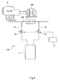
FIG. 1 is a diagram schematically illustrating a configuration of an exhaust gas analyzing system of the present embodiment; -
FIG. 2 is a diagram illustrating a sampling path and air introduction path in the same embodiment; -
FIG. 3 is a diagram illustrating a switching mechanism according to a variation; and -
FIG. 4 is a diagram schematically illustrating a configuration of another exhaust gas analyzing system. - In the following, one embodiment of an exhaust gas analyzing system according to the present invention is described referring to the drawings.
- An exhaust
gas analyzing system 100 according to the present embodiment is one that analyzes exhaust gas from an engine attached to anengine dynamo 200. - Specifically, the exhaust
gas analyzing system 100 is provided with: anexhaust gas analyzer 2 serving as an analytical instrument that analyzes the exhaust gas from the engine E; an exhaustgas introduction pipe 3 of which one end is opened to an exhaust gas flow path through which the exhaust gas from the engine E attached to the engine dynamo 200 flows and the other end is connected to theexhaust gas analyzer 2; aswitching mechanism 4 that is provided in the exhaustgas introduction pipe 3 and selectively switches between a sampling path L1 that samples the exhaust gas from the exhaustgas introduction pipe 3 and an air introduction path L2 that introduces air; and acontrol device 5 that controls theswitching mechanism 4. Note that the exhaustgas introduction pipe 3, theswitching mechanism 4, and thecontrol device 5 constitute an exhaust gas sampling device. - The
exhaust gas analyzer 2 is one that measures concentrations of measurement components contained in the exhaust gas, and measures concentrations of, for example, CO and CO2 by an NDIR method, THC by an FID method, and NOx by a CLD method. - Also, in the exhaust
gas flow path 300, on upstream and downstream sides with respect to the one end opening of the exhaustgas introduction pipe 3, exhaust gas purification catalysts for purifying the exhaust gas are respectively provided. - The
switching mechanism 4 of the present embodiment is configured to have a three way solenoid valve that is provided in the exhaustgas introduction pipe 3. The threeway solenoid valve 4 has: an upstream side port (first port) P1 that is connected with anupstream side pipe 31 constituting the exhaustgas introduction pipe 3; a downstream side port (second port) P2 that is connected with adownstream side pipe 32 constituting the exhaustgas introduction pipe 3; and an air opening port (third port) P3 that is opened to air. In addition, an upstream side opening of theupstream side pipe 31 is opened into the exhaustgas flow path 300. Also, a downstream side of thedownstream side pipe 32 is connected to a gas introduction port of theexhaust gas analyzer 2. In addition, the air opening port P3 may be connected with a pipe that is opened to air. - The three
way solenoid valve 4 is controlled by the after-mentionedcontrol device 5, and as illustrated inFIG. 2 , selectively switches between the sampling path L1 (seeFIG. 2 (A) ) that communicatively connects the upstream side port P1 and downstream side port P2 with each other and the air introduction path L2 (seeFIG. 2 (B) ) that communicatively connects the air opening port P3 and downstream side port P2 with each other. In order to enhance switching responsiveness, the threeway solenoid valve 4 is preferably close to a sampling point, and in the present embodiment, provided in the exhaustgas introduction pipe 3 near outside a pipe forming the exhaustgas flow path 300. - The
control device 5 is a dedicated or general-purpose computer that is provided with a CPU, a memory, an I/O channel, an A/D converter, and the like, and according to a control program stored in the memory, the CPU and its peripheral devices cooperatively works to thereby switch the threeway solenoid valve 4 serving as the switching mechanism in accordance with operation/stop of the engine E. - Specifically, when the engine E is in an operating state, the
control device 5 controls the threeway solenoid valve 4 to thereby establish the sampling path L1, whereas when the engine E is stopped, thecontrol device 5 controls the threeway solenoid valve 4 to thereby establish the air introduction path L2. On the basis of this, when the engine E is operated (rotated), a sample is introduced into theexhaust gas analyzer 2, whereas when the engine E is stopped, air is introduced into theexhaust gas analyzer 2. - The
control device 5 performs the switching control of the threeway solenoid valve 4 on the basis of an engine operation related signal obtained from the engine E or a peripheral device of the engine E. The engine operation related signal is a signal indicating whether or not the internal combustion engine is in the operating state, i.e., the engine E is rotated (operation (ON)/stop (OFF) of the engine E), and for example, a detection signal obtained from a pickup sensor that detects a rotation number of the engine E, an ignition signal of the engine E, an engine rotation number signal obtained by analyzing vibration or noise of the engine E, an engine rotation number signal obtained from theengine dynamo 200 serving as a peripheral device, an exhaust gas flow rate signal obtained from a flow rate sensor that detects a flow rate of the exhaust gas that flows through the exhaustgas flow path 300, an intake air flow rate signal obtained from a flow rate sensor that detects an intake air flow rate of the engine E, or other signal. - The
control device 5 obtains the above engine operation related signal to determine whether or not the engine E is being rotated (ON/OFF of the engine E), and if determining that the engine E is OFF, switches the threeway solenoid valve 4 to establish the air introduction path L2. On the other hand, if determining that the engine E is ON, thecontrol device 5 switches the threeway solenoid valve 4 to establish the sampling path L1. - Note that in the case of using any of the above signals as the engine operation related signal, switching timing may be delayed relative to actual engine operation. In such a case, as the engine operation related signal, an engine starting signal may be alternatively used. Alternatively, for example, in the case where as with an idling stop vehicle, ON/OFF of the engine E is clearly distinguished in a test mode interval, by using, as the engine operation related signal, an analysis signal obtained by analyzing a test mode, the
switching mechanism 4 can also be switched at timing to switch ON/OFF the engine E to thereby switch between the sampling path L1 and the air introduction path L2. - According to the exhaust
gas analyzing system 100 according to the present embodiment configured as described, the threeway solenoid valve 4 establishes the sampling path L1 when the engine is operated, whereas when the engine is stopped, it establishes the air introduction path L2, and therefore even in the case where theexhaust gas analyzer 2 remains operated, the gas is never sucked from the exhaustgas flow path 300 to the exhaustgas introduction pipe 3 when the engine is stopped. This enables the problems such as an unexpected gas flow, catalyst temperature change, and pressure reduction of an exhaust port in the exhaustgas flow path 300 at the time of engine stop to be solved. - Also, even at the time of engine stop, it is not necessary to stop the pump of the
exhaust gas analyzer 2, and therefore the problem due to a delay of the rise at the time of pump start or the inertia at the time of pump stop can also be solved. - Further, the use of the three
way solenoid valve 4 enables not only a configuration of theexhaust gas analyzer 100 to be simplified and cost to be reduced to achieve a low price but an operation to be simplified. - In addition, by providing the three
way solenoid valve 4, in the case like a warm up mode in which the exhaust gas is not sampled, gas can be flowed back from theexhaust gas analyzer 2 side to purge the exhaustgas introduction pipe 3. Also, even in the situation where in the case of making long time measurements, purging is required along the way, the purging can be performed without influencing the engine E side. - Note that the present invention is not limited to the above-described embodiment.
- In the case of stopping or starting the measurement in accordance with the stop or operation of the engine, corresponding timing is important. In the case of the exhaust
gas analyzing system 100 that performs exhaust gas sampling, a delay time caused by the exhaust gas that flows from the sampling point to theanalytical instrument 2 is also important for improving accuracy of exhaust amount calculation. The delay time is different depending on the type of theanalytical instrument 2 or a pipe length, and therefore it is preferable to measure a delay time for each component to correct the delay time at the time of calculating the exhaust amount. - In order to measure the delay time, for example, standard gas of which component concentrations are known, or the like, is supplied to the upstream side opening of the exhaust gas introduction pipe, and a gas flow path is switched to the sampling path by the switching mechanism. By comparing timing of the switching with rise timing of an indication of the analytical instrument, a delay time at the time of measurement start is known. Similarly, in a state where the standard gas of which the concentrations are known, or the like, is flowed, the gas flow path is switched to the air introduction path by the switching mechanism. By comparing timing of the switching with a fall timing of the indication of the analytical instrument, a delay time at the time of measurement stop is known. Note that without separately providing a supply mechanism that supplies the standard gas of which the component concentrations are known, by bringing the engine into a steady state to make an exhaust gas concentration constant, a similar delay time can be measured.
- Also, in the above-described embodiment, the
switching mechanism 4 is the three way solenoid valve, and thecontrol device 5 obtains the engine operation related signal to automatically switch the threeway solenoid valve 4; however, a user may operate thecontrol device 5 to thereby switch the threeway solenoid valve 4. - Also, the present invention may be configured such that the
switching mechanism 4 is configured to have a three way valve and a user manually switches the three way valve. - Further, the exhaust gas analyzing system of the above-described embodiment employs the
exhaust gas analyzer 2 as an analytical instrument; however, the exhaust gas analyzing system may employ a PM analyzer instead. - Besides, the present invention may be configured such that as the
switching mechanism 4, as illustrated inFIG. 3 , anair opening pipe 41 that is branched from the exhaustgas introduction pipe 3 is provided, and on upstream sides of a point of the branch P, on/offvalves - In addition, the present invention may be adapted to use the exhaust
gas analyzing system 100 to sample exhaust gas from each of upstream and downstream sides of an exhaust gas purification catalyst provided on the exhaustgas flow path 300, and analyze the sampled exhaust gas to thereby analyze purification efficiency of the catalyst. In this case, the exhaustgas analyzing system 100 is, as illustrated inFIG. 4 , provided with: a first exhaustgas introduction pipe 3A that samples exhaust gas from the upstream side of the exhaust gas purification catalyst; and a second exhaustgas introduction pipe 3B that samples exhaust gas from the downstream side of the exhaust gas purification catalyst, and each of the first and second exhaustgas introduction pipes switching mechanism - Besides, it should be appreciated that the present invention is not limited to any of the above-described embodiments, but can be variously modified without departing from the scope thereof.
-
- 100: Exhaust gas analyzing system
- 300: Exhaust gas flow path
- 2: Exhaust gas analyzer (analytical instrument)
- 3: Exhaust gas introduction pipe
- L1: Sampling path
- L2: Air introduction path
- 4: Switching mechanism (three way solenoid valve)
- 5: Control device
Claims (4)
- An exhaust gas analyzing system comprising, on an upstream side of an analytical instrument,
an exhaust gas introduction pipe of which one end is opened to an exhaust gas flow path through which exhaust gas from an engine flows and the other end is connected to the analytical instrument, and
a switching mechanism that selectively switches between a sampling path that samples the exhaust gas from the exhaust gas introduction pipe to introduce the sampled exhaust gas into the analytical instrument and an air introduction path that introduces air into the analytical instrument, wherein
when the engine is operated, a path to the analytical instrument is switched to the sampling path by the switching mechanism, whereas when the engine is stopped, the path is switched to the air introduction path by the switching mechanism. - The exhaust gas analyzing system according to claim 1, wherein
the exhaust gas introduction pipe has: an upstream side pipe of which one end is opened to the exhaust gas flow path; and a downstream side pipe of which another end is connected to the analytical instrument, and
the switching mechanism is a three way valve of which a first port is connected to the upstream side pipe, a second port is connected with the downstream side pipe, and a third port is opened to air. - The exhaust gas analyzing system according to claim 1, wherein
a control device that has received an engine operation related signal indicating whether or not the engine is in an operating state controls the switching mechanism. - An exhaust gas analyzing method comprising, on an upstream side of an analytical instrument,
an exhaust gas introduction pipe of which one end is opened to an exhaust gas flow path through which exhaust gas from an engine flows and the other end is connected to the analytical instrument, and
a switching mechanism that selectively switches between a sampling path that samples the exhaust gas from the exhaust gas introduction pipe to introduce the sampled exhaust gas into the analytical instrument and an air introduction path that introduces air into the analytical instrument, wherein
when the engine is operated, a path to the analytical instrument is switched to the sampling path by the switching mechanism, whereas when the engine is stopped, the path is switched to the air introduction path by the switching mechanism.
Applications Claiming Priority (1)
| Application Number | Priority Date | Filing Date | Title |
|---|---|---|---|
| JP2010289654A JP2012137374A (en) | 2010-12-27 | 2010-12-27 | Exhaust gas analysis system and exhaust gas analysis method |
Publications (2)
| Publication Number | Publication Date |
|---|---|
| EP2469259A1 true EP2469259A1 (en) | 2012-06-27 |
| EP2469259B1 EP2469259B1 (en) | 2014-02-19 |
Family
ID=45531128
Family Applications (1)
| Application Number | Title | Priority Date | Filing Date |
|---|---|---|---|
| EP11010203.5A Revoked EP2469259B1 (en) | 2010-12-27 | 2011-12-22 | Exhaust gas analyzing system and exhaust gas analyzing method |
Country Status (5)
| Country | Link |
|---|---|
| US (1) | US9074512B2 (en) |
| EP (1) | EP2469259B1 (en) |
| JP (1) | JP2012137374A (en) |
| CN (1) | CN102590445B (en) |
| DE (1) | DE202011110972U1 (en) |
Cited By (3)
| Publication number | Priority date | Publication date | Assignee | Title |
|---|---|---|---|---|
| JP2016040458A (en) * | 2014-08-12 | 2016-03-24 | 株式会社堀場製作所 | Information processing apparatus for exhaust gas measurement, exhaust gas measurement system and program |
| US9297726B2 (en) | 2012-05-23 | 2016-03-29 | Avl Test Systems, Inc. | Exhaust sampling system and method for water vapor management |
| US9518897B2 (en) | 2012-05-29 | 2016-12-13 | Avl Test Systems, Inc. | Intelligent bag filling for exhaust sampling system |
Families Citing this family (15)
| Publication number | Priority date | Publication date | Assignee | Title |
|---|---|---|---|---|
| JP5728366B2 (en) * | 2011-11-10 | 2015-06-03 | 株式会社堀場製作所 | Exhaust gas analyzer, exhaust gas analyzer management device, and exhaust gas analyzer management program |
| CN103454091B (en) * | 2013-09-12 | 2016-02-10 | 中国船舶重工集团公司第七一一研究所 | The flowing property token test device of internal combustion engine tee air inlet-outlet pipe |
| DE112016000305T5 (en) * | 2015-01-09 | 2017-09-28 | Avl Test Systems, Inc. | SYSTEM AND METHOD FOR DETECTING A LEAKAGE IN AN EXHAUST SAMPLING DEVICE |
| JP6752591B2 (en) * | 2015-04-24 | 2020-09-09 | 株式会社堀場製作所 | Exhaust gas measuring device |
| JP6646520B2 (en) * | 2016-05-24 | 2020-02-14 | 株式会社堀場製作所 | Exhaust gas analysis system, exhaust gas analysis system program, and exhaust gas analysis method |
| CN106644611A (en) * | 2017-02-16 | 2017-05-10 | 大友(苏州)风洞技术有限公司 | Discharge sampling tester of engine plateau simulation system |
| CN107143404B (en) * | 2017-04-20 | 2023-06-02 | 同济大学 | A diesel engine combined post-processor emission reduction performance test system |
| CN109254108B (en) * | 2017-07-12 | 2023-02-17 | 株式会社堀场制作所 | Analysis device and analysis method |
| US10724924B2 (en) | 2017-09-13 | 2020-07-28 | Avl Test Systems, Inc. | System and method for determining whether an engine is on or off based on a pressure of exhaust gas produced by the engine |
| JP6956002B2 (en) * | 2017-12-27 | 2021-10-27 | 株式会社堀場製作所 | Exhaust gas sampling device, exhaust gas analysis system, exhaust gas sampling method, and exhaust gas sampling program |
| CN108593856A (en) * | 2018-06-21 | 2018-09-28 | 天津索克汽车试验有限公司 | A kind of exhaust gas post-treatment device gas concentration measurement point switching device |
| CN110261124B (en) * | 2019-05-22 | 2021-07-16 | 同济大学 | Construction Method and Application of Particulate Matter Distribution Model in Diesel Engine Exhaust Aftertreatment System |
| CN113125160B (en) * | 2019-12-30 | 2023-08-18 | 宇通客车股份有限公司 | New energy vehicle emission detection device, emission test system and emission detection method |
| JP7820800B2 (en) * | 2022-02-18 | 2026-02-26 | 国立研究開発法人 海上・港湾・航空技術研究所 | Combustion gas analysis system and combustion gas analysis method |
| CN116754144B (en) * | 2023-06-01 | 2026-04-21 | 东风越野车有限公司 | A method and apparatus for detecting oil leakage in an engine exhaust system |
Citations (2)
| Publication number | Priority date | Publication date | Assignee | Title |
|---|---|---|---|---|
| EP0668495A2 (en) * | 1994-02-17 | 1995-08-23 | Pierburg Aktiengesellschaft | Measuring installation for the exhaust particles (soot) of combustion engines |
| JP2010139340A (en) | 2008-12-10 | 2010-06-24 | Toyota Motor Corp | Exhaust gas measuring device |
Family Cites Families (17)
| Publication number | Priority date | Publication date | Assignee | Title |
|---|---|---|---|---|
| SE7513901L (en) | 1974-12-19 | 1976-06-21 | United Technologies Corp | VEHICLE EXHAUST SYSTEM ANALYSIS. |
| US3957372A (en) | 1974-12-19 | 1976-05-18 | United Technologies Corporation | Vehicle exhaust gas analysis system |
| JPH0416197Y2 (en) * | 1984-11-07 | 1992-04-10 | ||
| JPS61247938A (en) * | 1985-04-25 | 1986-11-05 | Mazda Motor Corp | Measuring instrument for exhaust gas |
| JP2503232B2 (en) * | 1987-07-31 | 1996-06-05 | 日立テクノエンジニアリング株式会社 | Exhaust gas attracting device for engine |
| US6176125B1 (en) * | 1997-01-25 | 2001-01-23 | Horiba, Ltd. | Exhaust gas flow measuring equipment for internal combustion engines and processes for calibrating sensitivity of trace gas flow meters |
| JP3374077B2 (en) * | 1998-05-12 | 2003-02-04 | 株式会社堀場製作所 | Exhaust gas sampling device |
| JP2000221123A (en) * | 1999-02-01 | 2000-08-11 | Honda Motor Co Ltd | Exhaust gas sampling method |
| US6715338B1 (en) * | 1998-08-28 | 2004-04-06 | Taiwan Semiconductor Manufacturing Co., Ltd | Apparatus and method for detecting flammable gas in a gas mixture |
| JP4246867B2 (en) * | 1999-12-06 | 2009-04-02 | 株式会社堀場製作所 | Exhaust gas analysis system |
| US7404340B2 (en) * | 2001-07-10 | 2008-07-29 | Caterpillar Inc. | Exhaust gas particulate measuring system |
| US6615677B2 (en) * | 2001-07-10 | 2003-09-09 | Caterpillar Inc | Method for controlling dilution air |
| JP4300350B2 (en) * | 2003-08-08 | 2009-07-22 | 日産自動車株式会社 | Exhaust gas measuring device and exhaust gas measuring method |
| JP2009145219A (en) * | 2007-12-14 | 2009-07-02 | Denso Corp | NOx sensor diagnostic device for internal combustion engine |
| CN201149546Y (en) * | 2007-12-26 | 2008-11-12 | 江苏大学 | A vehicle fuel consumption test device measured by exhaust dilution |
| CN101196435A (en) * | 2007-12-26 | 2008-06-11 | 江苏大学 | A vehicle fuel consumption test device measured by exhaust dilution |
| JP2010139281A (en) * | 2008-12-09 | 2010-06-24 | Toyota Motor Corp | Instrument for measuring exhaust gas |
-
2010
- 2010-12-27 JP JP2010289654A patent/JP2012137374A/en active Pending
-
2011
- 2011-12-22 EP EP11010203.5A patent/EP2469259B1/en not_active Revoked
- 2011-12-22 DE DE202011110972.4U patent/DE202011110972U1/en not_active Expired - Lifetime
- 2011-12-23 US US13/336,094 patent/US9074512B2/en not_active Expired - Fee Related
- 2011-12-23 CN CN201110439516.2A patent/CN102590445B/en not_active Expired - Fee Related
Patent Citations (2)
| Publication number | Priority date | Publication date | Assignee | Title |
|---|---|---|---|---|
| EP0668495A2 (en) * | 1994-02-17 | 1995-08-23 | Pierburg Aktiengesellschaft | Measuring installation for the exhaust particles (soot) of combustion engines |
| JP2010139340A (en) | 2008-12-10 | 2010-06-24 | Toyota Motor Corp | Exhaust gas measuring device |
Cited By (5)
| Publication number | Priority date | Publication date | Assignee | Title |
|---|---|---|---|---|
| US9297726B2 (en) | 2012-05-23 | 2016-03-29 | Avl Test Systems, Inc. | Exhaust sampling system and method for water vapor management |
| US9518897B2 (en) | 2012-05-29 | 2016-12-13 | Avl Test Systems, Inc. | Intelligent bag filling for exhaust sampling system |
| US10422726B2 (en) | 2012-05-29 | 2019-09-24 | Avl Test Systems, Inc. | Intelligent bag filling for exhaust sampling system |
| US10921220B2 (en) | 2012-05-29 | 2021-02-16 | Avl Test Systems, Inc. | Intelligent bag filling for exhaust sampling system |
| JP2016040458A (en) * | 2014-08-12 | 2016-03-24 | 株式会社堀場製作所 | Information processing apparatus for exhaust gas measurement, exhaust gas measurement system and program |
Also Published As
| Publication number | Publication date |
|---|---|
| CN102590445B (en) | 2015-08-05 |
| CN102590445A (en) | 2012-07-18 |
| JP2012137374A (en) | 2012-07-19 |
| EP2469259B1 (en) | 2014-02-19 |
| US20120160009A1 (en) | 2012-06-28 |
| DE202011110972U1 (en) | 2017-11-20 |
| US9074512B2 (en) | 2015-07-07 |
Similar Documents
| Publication | Publication Date | Title |
|---|---|---|
| EP2469259B1 (en) | Exhaust gas analyzing system and exhaust gas analyzing method | |
| MX2015001896A (en) | Method of diagnosing an exhaust gas sensor. | |
| US20110056269A1 (en) | Method for Determining the Oxygen Storage Capacity | |
| JP6646520B2 (en) | Exhaust gas analysis system, exhaust gas analysis system program, and exhaust gas analysis method | |
| US10767542B2 (en) | Exhaust gas sampling apparatus, exhaust gas analysis system, exhaust gas sampling method, and exhaust gas sampling program | |
| JP2011242194A (en) | Exhaust gas measuring instrument and method for collecting exhaust gas | |
| JP6235106B2 (en) | Exhaust gas analysis system and exhaust gas analysis method | |
| JP2010139340A (en) | Exhaust gas measuring device | |
| JP4925489B1 (en) | Gas analyzer | |
| EP2755012A1 (en) | Gas analysis device and contamination detection method used in same | |
| US8041501B2 (en) | Method and system for monitoring an active hydrocarbon adsorber | |
| JP6051198B2 (en) | Exhaust gas analysis system and exhaust gas analysis method | |
| JP2010139281A (en) | Instrument for measuring exhaust gas | |
| JP4390737B2 (en) | Exhaust gas measuring device and exhaust gas measuring method | |
| JP6302593B1 (en) | Exhaust gas analyzer | |
| CN105223022A (en) | A kind of catalyzer checking device based on engine pedestal and method | |
| JP7778092B2 (en) | On-board exhaust gas analyzer and exhaust gas analysis method | |
| JP4300350B2 (en) | Exhaust gas measuring device and exhaust gas measuring method | |
| WO2023063139A1 (en) | Exhaust gas sampling device, exhaust gas analysis system, exhaust gas sampling method, and program for exhaust gas sampling device | |
| JP2003161144A (en) | Method and apparatus for diagnosing deterioration of exhaust gas control device | |
| JP6397691B2 (en) | Exhaust gas analysis system and exhaust gas analysis method | |
| RU75243U1 (en) | GAS ANALYZER AMMONIA | |
| KR20080055042A (en) | How to measure engine exhaust gas | |
| JP2006214949A (en) | Exhaust gas measuring device | |
| JPH11230872A (en) | Gas dilution device |
Legal Events
| Date | Code | Title | Description |
|---|---|---|---|
| REG | Reference to a national code |
Ref country code: DE Ref legal event code: R138 Ref document number: 202011110972 Country of ref document: DE Free format text: GERMAN DOCUMENT NUMBER IS 602011004969 |
|
| AK | Designated contracting states |
Kind code of ref document: A1 Designated state(s): AL AT BE BG CH CY CZ DE DK EE ES FI FR GB GR HR HU IE IS IT LI LT LU LV MC MK MT NL NO PL PT RO RS SE SI SK SM TR |
|
| AX | Request for extension of the european patent |
Extension state: BA ME |
|
| PUAI | Public reference made under article 153(3) epc to a published international application that has entered the european phase |
Free format text: ORIGINAL CODE: 0009012 |
|
| 17P | Request for examination filed |
Effective date: 20121221 |
|
| RIC1 | Information provided on ipc code assigned before grant |
Ipc: F02B 77/08 20060101ALI20130712BHEP Ipc: G01M 15/10 20060101AFI20130712BHEP |
|
| GRAP | Despatch of communication of intention to grant a patent |
Free format text: ORIGINAL CODE: EPIDOSNIGR1 |
|
| INTG | Intention to grant announced |
Effective date: 20130823 |
|
| GRAS | Grant fee paid |
Free format text: ORIGINAL CODE: EPIDOSNIGR3 |
|
| GRAA | (expected) grant |
Free format text: ORIGINAL CODE: 0009210 |
|
| AK | Designated contracting states |
Kind code of ref document: B1 Designated state(s): AL AT BE BG CH CY CZ DE DK EE ES FI FR GB GR HR HU IE IS IT LI LT LU LV MC MK MT NL NO PL PT RO RS SE SI SK SM TR |
|
| REG | Reference to a national code |
Ref country code: GB Ref legal event code: FG4D |
|
| REG | Reference to a national code |
Ref country code: CH Ref legal event code: EP |
|
| REG | Reference to a national code |
Ref country code: AT Ref legal event code: REF Ref document number: 652893 Country of ref document: AT Kind code of ref document: T Effective date: 20140315 |
|
| REG | Reference to a national code |
Ref country code: DE Ref legal event code: R096 Ref document number: 602011004969 Country of ref document: DE Effective date: 20140403 |
|
| REG | Reference to a national code |
Ref country code: IE Ref legal event code: FG4D |
|
| REG | Reference to a national code |
Ref country code: SE Ref legal event code: TRGR |
|
| REG | Reference to a national code |
Ref country code: NL Ref legal event code: VDEP Effective date: 20140219 |
|
| REG | Reference to a national code |
Ref country code: AT Ref legal event code: MK05 Ref document number: 652893 Country of ref document: AT Kind code of ref document: T Effective date: 20140219 |
|
| REG | Reference to a national code |
Ref country code: LT Ref legal event code: MG4D |
|
| PG25 | Lapsed in a contracting state [announced via postgrant information from national office to epo] |
Ref country code: LT Free format text: LAPSE BECAUSE OF FAILURE TO SUBMIT A TRANSLATION OF THE DESCRIPTION OR TO PAY THE FEE WITHIN THE PRESCRIBED TIME-LIMIT Effective date: 20140219 Ref country code: NO Free format text: LAPSE BECAUSE OF FAILURE TO SUBMIT A TRANSLATION OF THE DESCRIPTION OR TO PAY THE FEE WITHIN THE PRESCRIBED TIME-LIMIT Effective date: 20140519 Ref country code: IS Free format text: LAPSE BECAUSE OF FAILURE TO SUBMIT A TRANSLATION OF THE DESCRIPTION OR TO PAY THE FEE WITHIN THE PRESCRIBED TIME-LIMIT Effective date: 20140619 |
|
| PG25 | Lapsed in a contracting state [announced via postgrant information from national office to epo] |
Ref country code: PT Free format text: LAPSE BECAUSE OF FAILURE TO SUBMIT A TRANSLATION OF THE DESCRIPTION OR TO PAY THE FEE WITHIN THE PRESCRIBED TIME-LIMIT Effective date: 20140619 Ref country code: FI Free format text: LAPSE BECAUSE OF FAILURE TO SUBMIT A TRANSLATION OF THE DESCRIPTION OR TO PAY THE FEE WITHIN THE PRESCRIBED TIME-LIMIT Effective date: 20140219 Ref country code: CY Free format text: LAPSE BECAUSE OF FAILURE TO SUBMIT A TRANSLATION OF THE DESCRIPTION OR TO PAY THE FEE WITHIN THE PRESCRIBED TIME-LIMIT Effective date: 20140219 Ref country code: ES Free format text: LAPSE BECAUSE OF FAILURE TO SUBMIT A TRANSLATION OF THE DESCRIPTION OR TO PAY THE FEE WITHIN THE PRESCRIBED TIME-LIMIT Effective date: 20140219 Ref country code: AT Free format text: LAPSE BECAUSE OF FAILURE TO SUBMIT A TRANSLATION OF THE DESCRIPTION OR TO PAY THE FEE WITHIN THE PRESCRIBED TIME-LIMIT Effective date: 20140219 Ref country code: NL Free format text: LAPSE BECAUSE OF FAILURE TO SUBMIT A TRANSLATION OF THE DESCRIPTION OR TO PAY THE FEE WITHIN THE PRESCRIBED TIME-LIMIT Effective date: 20140219 |
|
| PG25 | Lapsed in a contracting state [announced via postgrant information from national office to epo] |
Ref country code: LV Free format text: LAPSE BECAUSE OF FAILURE TO SUBMIT A TRANSLATION OF THE DESCRIPTION OR TO PAY THE FEE WITHIN THE PRESCRIBED TIME-LIMIT Effective date: 20140219 Ref country code: HR Free format text: LAPSE BECAUSE OF FAILURE TO SUBMIT A TRANSLATION OF THE DESCRIPTION OR TO PAY THE FEE WITHIN THE PRESCRIBED TIME-LIMIT Effective date: 20140219 Ref country code: BE Free format text: LAPSE BECAUSE OF FAILURE TO SUBMIT A TRANSLATION OF THE DESCRIPTION OR TO PAY THE FEE WITHIN THE PRESCRIBED TIME-LIMIT Effective date: 20140219 Ref country code: RS Free format text: LAPSE BECAUSE OF FAILURE TO SUBMIT A TRANSLATION OF THE DESCRIPTION OR TO PAY THE FEE WITHIN THE PRESCRIBED TIME-LIMIT Effective date: 20140219 |
|
| PG25 | Lapsed in a contracting state [announced via postgrant information from national office to epo] |
Ref country code: EE Free format text: LAPSE BECAUSE OF FAILURE TO SUBMIT A TRANSLATION OF THE DESCRIPTION OR TO PAY THE FEE WITHIN THE PRESCRIBED TIME-LIMIT Effective date: 20140219 Ref country code: CZ Free format text: LAPSE BECAUSE OF FAILURE TO SUBMIT A TRANSLATION OF THE DESCRIPTION OR TO PAY THE FEE WITHIN THE PRESCRIBED TIME-LIMIT Effective date: 20140219 Ref country code: DK Free format text: LAPSE BECAUSE OF FAILURE TO SUBMIT A TRANSLATION OF THE DESCRIPTION OR TO PAY THE FEE WITHIN THE PRESCRIBED TIME-LIMIT Effective date: 20140219 Ref country code: RO Free format text: LAPSE BECAUSE OF FAILURE TO SUBMIT A TRANSLATION OF THE DESCRIPTION OR TO PAY THE FEE WITHIN THE PRESCRIBED TIME-LIMIT Effective date: 20140219 |
|
| REG | Reference to a national code |
Ref country code: DE Ref legal event code: R026 Ref document number: 602011004969 Country of ref document: DE |
|
| PLBI | Opposition filed |
Free format text: ORIGINAL CODE: 0009260 |
|
| PG25 | Lapsed in a contracting state [announced via postgrant information from national office to epo] |
Ref country code: PL Free format text: LAPSE BECAUSE OF FAILURE TO SUBMIT A TRANSLATION OF THE DESCRIPTION OR TO PAY THE FEE WITHIN THE PRESCRIBED TIME-LIMIT Effective date: 20140219 Ref country code: SK Free format text: LAPSE BECAUSE OF FAILURE TO SUBMIT A TRANSLATION OF THE DESCRIPTION OR TO PAY THE FEE WITHIN THE PRESCRIBED TIME-LIMIT Effective date: 20140219 |
|
| PLAX | Notice of opposition and request to file observation + time limit sent |
Free format text: ORIGINAL CODE: EPIDOSNOBS2 |
|
| 26 | Opposition filed |
Opponent name: AVL EMISSION TEST SYSTEMS GMBH Effective date: 20141119 |
|
| REG | Reference to a national code |
Ref country code: DE Ref legal event code: R026 Ref document number: 602011004969 Country of ref document: DE Effective date: 20141119 |
|
| PG25 | Lapsed in a contracting state [announced via postgrant information from national office to epo] |
Ref country code: RS Free format text: LAPSE BECAUSE OF FAILURE TO SUBMIT A TRANSLATION OF THE DESCRIPTION OR TO PAY THE FEE WITHIN THE PRESCRIBED TIME-LIMIT Effective date: 20140903 |
|
| PG25 | Lapsed in a contracting state [announced via postgrant information from national office to epo] |
Ref country code: IT Free format text: LAPSE BECAUSE OF FAILURE TO SUBMIT A TRANSLATION OF THE DESCRIPTION OR TO PAY THE FEE WITHIN THE PRESCRIBED TIME-LIMIT Effective date: 20140219 |
|
| PLAF | Information modified related to communication of a notice of opposition and request to file observations + time limit |
Free format text: ORIGINAL CODE: EPIDOSCOBS2 |
|
| PG25 | Lapsed in a contracting state [announced via postgrant information from national office to epo] |
Ref country code: SI Free format text: LAPSE BECAUSE OF FAILURE TO SUBMIT A TRANSLATION OF THE DESCRIPTION OR TO PAY THE FEE WITHIN THE PRESCRIBED TIME-LIMIT Effective date: 20140219 |
|
| PLBB | Reply of patent proprietor to notice(s) of opposition received |
Free format text: ORIGINAL CODE: EPIDOSNOBS3 |
|
| PG25 | Lapsed in a contracting state [announced via postgrant information from national office to epo] |
Ref country code: LU Free format text: LAPSE BECAUSE OF FAILURE TO SUBMIT A TRANSLATION OF THE DESCRIPTION OR TO PAY THE FEE WITHIN THE PRESCRIBED TIME-LIMIT Effective date: 20141222 |
|
| REG | Reference to a national code |
Ref country code: CH Ref legal event code: PL |
|
| REG | Reference to a national code |
Ref country code: IE Ref legal event code: MM4A |
|
| PG25 | Lapsed in a contracting state [announced via postgrant information from national office to epo] |
Ref country code: CH Free format text: LAPSE BECAUSE OF NON-PAYMENT OF DUE FEES Effective date: 20141231 Ref country code: IE Free format text: LAPSE BECAUSE OF NON-PAYMENT OF DUE FEES Effective date: 20141222 Ref country code: LI Free format text: LAPSE BECAUSE OF NON-PAYMENT OF DUE FEES Effective date: 20141231 |
|
| REG | Reference to a national code |
Ref country code: FR Ref legal event code: PLFP Year of fee payment: 5 |
|
| PG25 | Lapsed in a contracting state [announced via postgrant information from national office to epo] |
Ref country code: SM Free format text: LAPSE BECAUSE OF FAILURE TO SUBMIT A TRANSLATION OF THE DESCRIPTION OR TO PAY THE FEE WITHIN THE PRESCRIBED TIME-LIMIT Effective date: 20140219 |
|
| PG25 | Lapsed in a contracting state [announced via postgrant information from national office to epo] |
Ref country code: MC Free format text: LAPSE BECAUSE OF FAILURE TO SUBMIT A TRANSLATION OF THE DESCRIPTION OR TO PAY THE FEE WITHIN THE PRESCRIBED TIME-LIMIT Effective date: 20140219 |
|
| PG25 | Lapsed in a contracting state [announced via postgrant information from national office to epo] |
Ref country code: GR Free format text: LAPSE BECAUSE OF FAILURE TO SUBMIT A TRANSLATION OF THE DESCRIPTION OR TO PAY THE FEE WITHIN THE PRESCRIBED TIME-LIMIT Effective date: 20140520 Ref country code: BG Free format text: LAPSE BECAUSE OF FAILURE TO SUBMIT A TRANSLATION OF THE DESCRIPTION OR TO PAY THE FEE WITHIN THE PRESCRIBED TIME-LIMIT Effective date: 20140219 |
|
| PG25 | Lapsed in a contracting state [announced via postgrant information from national office to epo] |
Ref country code: HU Free format text: LAPSE BECAUSE OF FAILURE TO SUBMIT A TRANSLATION OF THE DESCRIPTION OR TO PAY THE FEE WITHIN THE PRESCRIBED TIME-LIMIT; INVALID AB INITIO Effective date: 20111222 Ref country code: MT Free format text: LAPSE BECAUSE OF FAILURE TO SUBMIT A TRANSLATION OF THE DESCRIPTION OR TO PAY THE FEE WITHIN THE PRESCRIBED TIME-LIMIT Effective date: 20140219 Ref country code: TR Free format text: LAPSE BECAUSE OF FAILURE TO SUBMIT A TRANSLATION OF THE DESCRIPTION OR TO PAY THE FEE WITHIN THE PRESCRIBED TIME-LIMIT Effective date: 20140219 |
|
| REG | Reference to a national code |
Ref country code: FR Ref legal event code: PLFP Year of fee payment: 6 |
|
| RDAF | Communication despatched that patent is revoked |
Free format text: ORIGINAL CODE: EPIDOSNREV1 |
|
| STAA | Information on the status of an ep patent application or granted ep patent |
Free format text: STATUS: THE PATENT HAS BEEN GRANTED |
|
| APBM | Appeal reference recorded |
Free format text: ORIGINAL CODE: EPIDOSNREFNO |
|
| APBP | Date of receipt of notice of appeal recorded |
Free format text: ORIGINAL CODE: EPIDOSNNOA2O |
|
| APAH | Appeal reference modified |
Free format text: ORIGINAL CODE: EPIDOSCREFNO |
|
| APBQ | Date of receipt of statement of grounds of appeal recorded |
Free format text: ORIGINAL CODE: EPIDOSNNOA3O |
|
| REG | Reference to a national code |
Ref country code: FR Ref legal event code: PLFP Year of fee payment: 7 |
|
| PG25 | Lapsed in a contracting state [announced via postgrant information from national office to epo] |
Ref country code: MK Free format text: LAPSE BECAUSE OF FAILURE TO SUBMIT A TRANSLATION OF THE DESCRIPTION OR TO PAY THE FEE WITHIN THE PRESCRIBED TIME-LIMIT Effective date: 20140219 |
|
| PG25 | Lapsed in a contracting state [announced via postgrant information from national office to epo] |
Ref country code: AL Free format text: LAPSE BECAUSE OF FAILURE TO SUBMIT A TRANSLATION OF THE DESCRIPTION OR TO PAY THE FEE WITHIN THE PRESCRIBED TIME-LIMIT Effective date: 20140219 |
|
| PGFP | Annual fee paid to national office [announced via postgrant information from national office to epo] |
Ref country code: DE Payment date: 20191210 Year of fee payment: 9 Ref country code: SE Payment date: 20191210 Year of fee payment: 9 |
|
| PGFP | Annual fee paid to national office [announced via postgrant information from national office to epo] |
Ref country code: FR Payment date: 20191115 Year of fee payment: 9 |
|
| PGFP | Annual fee paid to national office [announced via postgrant information from national office to epo] |
Ref country code: GB Payment date: 20191219 Year of fee payment: 9 |
|
| REG | Reference to a national code |
Ref country code: DE Ref legal event code: R064 Ref document number: 602011004969 Country of ref document: DE Ref country code: DE Ref legal event code: R103 Ref document number: 602011004969 Country of ref document: DE |
|
| APBU | Appeal procedure closed |
Free format text: ORIGINAL CODE: EPIDOSNNOA9O |
|
| RDAG | Patent revoked |
Free format text: ORIGINAL CODE: 0009271 |
|
| STAA | Information on the status of an ep patent application or granted ep patent |
Free format text: STATUS: PATENT REVOKED |
|
| REG | Reference to a national code |
Ref country code: FI Ref legal event code: MGE |
|
| 27W | Patent revoked |
Effective date: 20200714 |
|
| GBPR | Gb: patent revoked under art. 102 of the ep convention designating the uk as contracting state |
Effective date: 20200714 |
|
| REG | Reference to a national code |
Ref country code: SE Ref legal event code: ECNC |