EP2469163A2 - Leuchte mit Betätigungsmitteln - Google Patents
Leuchte mit Betätigungsmitteln Download PDFInfo
- Publication number
- EP2469163A2 EP2469163A2 EP11194489A EP11194489A EP2469163A2 EP 2469163 A2 EP2469163 A2 EP 2469163A2 EP 11194489 A EP11194489 A EP 11194489A EP 11194489 A EP11194489 A EP 11194489A EP 2469163 A2 EP2469163 A2 EP 2469163A2
- Authority
- EP
- European Patent Office
- Prior art keywords
- actuating means
- luminaire
- housing
- lamp
- luminaire housing
- Prior art date
- Legal status (The legal status is an assumption and is not a legal conclusion. Google has not performed a legal analysis and makes no representation as to the accuracy of the status listed.)
- Granted
Links
- 230000003287 optical effect Effects 0.000 claims description 2
- 238000000034 method Methods 0.000 description 3
- 238000012790 confirmation Methods 0.000 description 2
- 238000012937 correction Methods 0.000 description 1
- 230000001419 dependent effect Effects 0.000 description 1
- 238000013461 design Methods 0.000 description 1
- 238000011161 development Methods 0.000 description 1
- 230000018109 developmental process Effects 0.000 description 1
- 238000009434 installation Methods 0.000 description 1
- 238000012549 training Methods 0.000 description 1
Images
Classifications
-
- F—MECHANICAL ENGINEERING; LIGHTING; HEATING; WEAPONS; BLASTING
- F21—LIGHTING
- F21V—FUNCTIONAL FEATURES OR DETAILS OF LIGHTING DEVICES OR SYSTEMS THEREOF; STRUCTURAL COMBINATIONS OF LIGHTING DEVICES WITH OTHER ARTICLES, NOT OTHERWISE PROVIDED FOR
- F21V23/00—Arrangement of electric circuit elements in or on lighting devices
- F21V23/04—Arrangement of electric circuit elements in or on lighting devices the elements being switches
-
- F—MECHANICAL ENGINEERING; LIGHTING; HEATING; WEAPONS; BLASTING
- F21—LIGHTING
- F21V—FUNCTIONAL FEATURES OR DETAILS OF LIGHTING DEVICES OR SYSTEMS THEREOF; STRUCTURAL COMBINATIONS OF LIGHTING DEVICES WITH OTHER ARTICLES, NOT OTHERWISE PROVIDED FOR
- F21V15/00—Protecting lighting devices from damage
- F21V15/01—Housings, e.g. material or assembling of housing parts
-
- F—MECHANICAL ENGINEERING; LIGHTING; HEATING; WEAPONS; BLASTING
- F21—LIGHTING
- F21V—FUNCTIONAL FEATURES OR DETAILS OF LIGHTING DEVICES OR SYSTEMS THEREOF; STRUCTURAL COMBINATIONS OF LIGHTING DEVICES WITH OTHER ARTICLES, NOT OTHERWISE PROVIDED FOR
- F21V31/00—Gas-tight or water-tight arrangements
Definitions
- the present invention relates to a luminaire having a preferably completely closed luminaire housing, are arranged in the actuating means for programming, configuration or control of the luminaire.
- Luminaires which are arranged for example in a larger building, are often connected via a bus to a central control unit, which controls the lights accordingly. For this it is u.a. required that the luminaires be assigned a corresponding operating address.
- Such programming or configuration of the lamp has hitherto often been done via an external device, such as a PC, which is connected via a corresponding adapter cable with the lamp.
- an external device such as a PC
- This procedure is usually already before the final installation of the lights are used, since already installed lights a corresponding interface for a cable is not readily accessible and thus the programming or configuration is associated with a higher cost.
- the interface to which the cable for an external device is connected is open to the outside or has an easy-open cover, which can lead to problems especially with lights of higher protection, since such lights in the As a rule, the housing should be sealed as well as possible in order to protect the components arranged inside the housing from external influences.
- buttons or switches for programming or configuration.
- the subsequent address assignment is now much easier, since no external devices must be connected.
- the button or switch can be operated, holes are usually provided in the luminaire housing for the buttons or switches, which in turn can lead to leaks.
- the button or switch connected to the electronics within the luminaire housing must be, so that the luminaire housing must still have openings for connecting cable in spite of everything.
- Object of the present invention is therefore to provide a lamp in which the means which are provided for programming or configuration of the lamp, can not lead to leaks in the lamp housing.
- a luminaire which has a preferably completely closed luminaire housing, in which actuating means for programming, configuration or control of the luminaire are arranged, wherein the luminaire housing and the actuation means are configured such that the actuation means can be operated from outside the luminaire housing and at the same time Luminaire housing is closed in the region of the actuating means.
- the lamp housing is tubular and the actuating means abut the inner circumference or on the inner wall of the tubular body, wherein the actuating means may be a capacitive sensor, which is designed as a flexible printed circuit board.
- the actuating means also comprise a plurality of operating areas, each triggering different functions when they are actuated.
- the luminaire housing is designed to be transparent at least in the area of the actuating means, in which case the actuation means may comprise optical elements, in particular LEDs for outputting information about the programming, configuration or control, and an inscription on the actuation means may be provided which shows the functions of the actuating means.
- the actuating means may also comprise optical elements, in particular LEDs for outputting information about the programming, configuration or control, and an inscription on the actuation means may be provided which shows the functions of the actuating means.
- the lamp housing may have such a label.
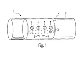
- FIG. 1 shows a lamp 1 according to the invention, wherein in FIG. 1 only the relevant for the invention section of the lamp 1 is shown.
- the lamp 1 according to the invention inter alia, a tubular lamp housing 2 and actuating means 3.
- the tubular luminaire housing 2 is in this case designed such that it is completely closed at least in the region in which the actuating means 3 are arranged.
- the luminaire housing 2 thus has no holes or openings in the area of the actuating means 3, as a result of which leaks in the luminaire housing 2 can not occur in this area, which is advantageous, in particular, in the case of luminaires with a higher degree of protection.
- the actuating means 3 have or are formed by a capacitive sensor, which is designed as a flexible printed circuit board. This makes it possible that the actuating means 3, as in FIG. 1 shown, abut the inner circumference or on the inner wall of the tubular lamp housing 2, whereby a programming, configuration or control of the lamp 1 can be made from the outside of the lamp housing 2 and additionally slipping of the actuating means 3 within the lamp 1 is largely prevented. It is particularly advantageous if the actuating means 3 have a similar shape as the tubular lamp housing 2.
- the design of the individual operating areas 4 depends essentially on what the actuating means 3 are to be used in detail.
- the actuating means can now be used in particular in the programming or configuration of the luminaire 1, for example in addressing.
- Another area of application is the control of a luminaire in normal operation. In this case, it would be conceivable, for example, for the lamp to be switched on and off or dimmed with the aid of the actuating means.
- actuating means 3 or operating areas 4 are now designed in particular for the address assignment, which will be explained in more detail by way of example.
- the luminaire housing 2 is designed to be substantially transparent, at least in the region of the actuating means 3, whereby at the in FIG. 1 shown embodiment, the actuating means 3 are visible from outside the lamp housing 2. Accordingly, the actuating means 3 also have a label 5 below the individual operating areas 4, which each briefly show the function of the individual operating areas 4. In addition, two LEDs 6 are arranged on the actuating means 3, which output, for example, in the address assignment information about the current status of the address assignment. Such a label could also be mounted on the lamp housing instead of on the actuating means, which is particularly advantageous in a non-transparent light housing.
- operating areas 4 are fields that are designed as s button. Conceivable, however, would be another training, for example as a sliding or rotary control.
- button of the controls 4 can now, as already explained, for example, a DMX address setting be made.
- the ⁇ +> and ⁇ -> keys are pressed together, then the ⁇ +> and ⁇ OK> keys and finally the ⁇ -> and ⁇ OK> keys.
- the lamp 1 of the invention changes into an addressing mode in which the one of the LEDs 6 permanently green lights.
- the "one" position of a DMX address can be set, the LEDs 6 give the user a corresponding feedback.
- the set value can then be accepted, again with confirmation via the LEDs 6.
- the same procedure can be used to enter the "tens" and "hundreds" digits of the address.
- a correction would be possible if the address was entered incorrectly, with the addressing process then starting again, for example.
- the address is input by a user directly to the luminaire 1 according to the invention. It would also be conceivable, for example, that the lamp is transmitted from a central control unit an address via a bus, which is then accepted by pressing a single button and taken over as a separate operating address for the light. In this case, it would be sufficient if the actuating means would have only one operating area with a button, since only confirmation would be necessary.
- luminaires in particular if they are designed as luminaires with a higher degree of protection or IP-protected luminaires, can also be used more frequently in outdoor areas, it can furthermore be provided that a specific, longer sequence of keys must be actuated before the start of addressing activate the luminaire or enable it for addressing. In this way it can be prevented that, on the one hand, an unauthorized input occurs due to unauthorized persons and, on the other hand, due to external influences, such as rain or the like, the luminaire is inadvertently reprogrammed.
- the actuating means are also provided for switching on and off the luminaire according to the invention.
- the actuating means could then have, for example, two operating areas.
Landscapes
- Engineering & Computer Science (AREA)
- General Engineering & Computer Science (AREA)
- Circuit Arrangement For Electric Light Sources In General (AREA)
- Non-Portable Lighting Devices Or Systems Thereof (AREA)
Abstract
Description
- Die vorliegende Erfindung betrifft eine Leuchte, die ein vorzugsweise vollständig geschlossenes Leuchtengehäuse aufweist, in dem Betätigungsmittel zur Programmierung, Konfiguration oder Steuerung der Leuchte angeordnet sind.
- Leuchten, die beispielsweise in einem größeren Gebäude angeordnet sind, werden häufig über einen Bus an eine zentrale Steuereinheit angeschlossen, die die Leuchten entsprechend steuert. Hierfür ist es u.a. erforderlich, dass den Leuchten eine entsprechende Betriebsadresse zugewiesen wird.
- Eine derartige Programmierung bzw. Konfiguration der Leuchte erfolgte bisher häufig über ein externes Gerät, beispielsweise einen PC, der über ein entsprechendes Adapterkabel mit der Leuchte verbunden wird. Diese Vorgehensweise kommt zumeist bereits vor der endgültigen Installation der Leuchten zum Einsatz, da bei bereits eingebauten Leuchten eine entsprechende Schnittstelle für ein Kabel nicht so ohne Weiteres frei zugänglich ist und dementsprechend die Programmierung bzw. Konfiguration mit einem höheren Aufwand verbunden ist. Zusätzlich ist es auch erforderlich, dass die Schnittstelle, an der das Kabel für ein externes Gerät angeschlossen wird, nach außen offen ist bzw. eine leicht zu öffnende Abdeckung aufweist, was insbesondere bei Leuchten höherer Schutzart zu Problemen führen kann, da derartige Leuchten in der Regel ein möglichst gut abgedichtetes Gehäuse aufweisen sollten, um die innerhalb des Gehäuses angeordneten Bauteile vor äußeren Einflüssen zu schützen.
- Eine ähnliche Problematik ergibt sich auch bei Leuchten, die Taster oder Schalter zur Programmierung oder Konfiguration aufweisen. Bei derartigen Leuchten ist zwar nun die nachträgliche Adressvergabe deutlich einfacher, da keine externen Geräte mehr angeschlossen werden müssen. Damit jedoch die Taster bzw. Schalter bedient werden können, sind im Leuchtengehäuse zumeist Bohrungen für die Taster bzw. Schalter vorgesehen, die wiederum zu Undichtigkeiten führen können. Auch bei der Anordnung der Taster oder Schalter außerhalb des Leuchtengehäuses besteht das Problem, dass die Taster bzw. Schalter mit der Elektronik innerhalb des Leuchtengehäuses verbunden werden müssen, wodurch das Leuchtengehäuse trotz allem Öffnungen für Verbindungskabel aufweisen muss.
- Aufgabe der vorliegenden Erfindung ist es somit, eine Leuchte zu schaffen, bei der die Mittel, welche zur Programmierung bzw. Konfiguration der Leuchte vorgesehen sind, nicht zu Undichtigkeiten des Leuchtengehäuses führen können.
- Die Aufgabe wird durch eine Leuchte gemäß Anspruch 1 gelöst. Vorteilhafte Weiterbildungen der Erfindung sind Gegenstand der abhängigen Ansprüche.
- Erfindungsgemäß wird eine Leuchte vorgeschlagen, die ein vorzugsweise vollständig geschlossenes Leuchtengehäuse aufweist, in dem Betätigungsmittel zur Programmierung, Konfiguration oder Steuerung der Leuchte angeordnet sind, wobei das Leuchtengehäuse und die Betätigungsmittel derart ausgestaltet sind, dass die Betätigungsmittel von außerhalb des Leuchtengehäuses bedienbar sind und gleichzeitig das Leuchtengehäuse im Bereich der Betätigungsmittel geschlossen ist.
- Hierbei kann es vorteilhafterweise vorgesehen sein, dass das Leuchtengehäuse rohrförmig ausgebildet ist und die Betätigungsmittel am Innenumfang bzw. an der Innenwand des rohrförmigen Körpers anliegen, wobei es sich bei den Betätigungsmitteln um eine kapazitive Sensorik handeln kann, die als flexible Leiterplatte ausgebildet ist.
- Bei der erfindungsgemäßen Leuchte sind nun keine nach außen ragenden Öffnungen für die Mittel zur Adressvergabe nötig, da die Betätigungsmittel zum einen innerhalb des an dieser Stelle geschlossenen Leuchtengehäuses angeordnet sind und zum anderen derart ausgestaltet sind, beispielsweise als kapazitive Sensorik, dass sie trotz des geschlossenen Leuchtengehäuses von außen bedienbar sind.
- Bei einer weiteren vorteilhaften Ausgestaltung der Erfindung, umfassen die Betätigungsmittel auch mehrere Bedienbereiche, die jeweils unterschiedliche Funktionen auslösen, wenn sie betätigt werden.
- Zusätzlich kann auch vorgesehen sein, dass das Leuchtengehäuse zumindest im Bereich der Betätigungsmittel transparent ausgebildet ist, wobei dann zum einen die Betätigungsmittel optische Elemente, insbesondere LEDs zur Ausgabe von Informationen über die Programmierung, Konfiguration oder Steuerung aufweisen können und zum anderen auf den Betätigungsmitteln eine Beschriftung vorgesehen sein kann, die die Funktionen der Betätigungsmittel zeigt. Anstelle der Betätigungsmittel kann aber auch das Leuchtengehäuse eine derartige Beschriftung aufweisen.
- Nachfolgend soll die Erfindung anhand von Ausführungsbeispielen und den beiliegenden Zeichnungen näher erläutert werden. Es zeigen:
-
Figur 1 : schematische Darstellung eines Teils einer erfindungsgemäßen Leuchte. -
Figur 1 zeigt eine erfindungsgemäße Leuchte 1, wobei inFigur 1 lediglich der für die Erfindung relevante Abschnitt der Leuchte 1 gezeigt ist. Wie ausFigur 1 hervorgeht, weist die erfindungsgemäße Leuchte 1 u.a. ein rohrförmiges Leuchtengehäuse 2 und Betätigungsmittel 3 auf. Das rohrförmige Leuchtengehäuse 2 ist hierbei derart ausgestaltet, dass es zumindest in dem Bereich, in dem die Betätigungsmittel 3 angeordnet sind, vollständig geschlossen ist. Das Leuchtengehäuse 2 weist somit im Bereich der Betätigungsmittel 3 keine Bohrungen bzw. Öffnungen auf, wodurch es in diesem Bereich nicht zu Undichtigkeiten des Leuchtengehäuses 2 kommen kann, was insbesondere bei Leuchten höherer Schutzart von Vorteil ist. - Die Betätigungsmittel 3 weisen eine kapazitive Sensorik auf bzw. sind durch diese gebildet, die als flexible Leiterplatte ausgebildet ist. Hierdurch ist es möglich, dass die Betätigungsmittel 3, wie in
Figur 1 gezeigt, am Innenumfang bzw. an der Innenwand des rohrförmigen Leuchtengehäuses 2 anliegen, wodurch eine Programmierung, Konfiguration oder Steuerung der Leuchte 1 von der Außenseite des Leuchtengehäuses 2 vorgenommen werden kann und zusätzlich ein Verrutschen der Betätigungsmittel 3 innerhalb der Leuchte 1 weitestgehend verhindert wird. Hierbei ist es insbesondere vorteilhaft, wenn die Betätigungsmittel 3 eine ähnliche Form wie das rohrförmige Leuchtengehäuse 2 aufweisen. - Die kapazitive Sensorik der Betätigungsmittel 3, die ähnlich einem Sensorfeld bei einer Herdplatte ausgeführt ist, weist dann zusätzlich auch noch mehrere Bedienbereiche 4 auf, durch deren Betätigung bzw. Anwählen dann im Einzelnen die Programmierung, Konfiguration oder Steuerung der erfindungsgemäßen Leuchte 1 vorgenommen werden kann. Die Ausgestaltung der einzelnen Bedienbereiche 4 hängt dabei im Wesentlichen davon ab, wofür die Betätigungsmittel 3 im Einzelnen eingesetzt werden sollen.
- Zum einen können die Betätigungsmittel nun insbesondere bei der Programmierung bzw. Konfiguration der Leuchte 1, beispielsweise bei der Adressierung, Anwendung finden. Ein anderer Anwendungsbereich ist die Steuerung einer Leuchte im Normalbetrieb. Hierbei wäre es beispielsweise denkbar, dass mit Hilfe der Betätigungsmittel die Leuchte ein- und ausgeschaltet oder gedimmt wird.
- Die in
Figur 1 gezeigten Betätigungsmittel 3 bzw. Bedienbereiche 4 sind nun insbesondere für die Adressvergabe ausgelegt, die beispielhaft noch näher erläutert werden soll. - Hierzu ist anzumerken, dass das Leuchtengehäuse 2 zumindest im Bereich der Betätigungsmittel 3 im Wesentlichen transparent ausgebildet ist, wodurch bei dem in
Figur 1 gezeigten Ausführungsbeispiel die Betätigungsmittel 3 auch von außerhalb des Leuchtengehäuses 2 sichtbar sind. Dementsprechend weisen die Betätigungsmittel 3 auch eine Beschriftung 5 unterhalb der einzelnen Bedienbereiche 4 auf, die jeweils kurz die Funktion der einzelnen Bedienbereiche 4 aufzeigen. Zusätzlich sind auf den Betätigungsmitteln 3 auch zwei Leuchtdioden 6 angeordnet, die beispielsweise bei der Adressvergabe Informationen über den aktuellen Status der Adressvergabe ausgeben. Eine derartige Beschriftung könnte aber auch anstatt auf den Betätigungsmitteln auf dem Leuchtengehäuse angebracht sein, was insbesondere bei einem nichttransparenten Leuchtengehäuse von Vorteil ist. - Bei den in
Figur 1 gezeigten Bedienbereichen 4 handelt es sich um Felder, die als s Taster ausgebildet sind. Denkbar wäre aber auch eine andere Ausbildung, beispielsweise als Schiebe- oder Drehregler. - Mit Hilfe der in
Figur 1 gezeigten Taster der Bedienelemente 4 kann nun, wie bereits erläutert, beispielsweise eine DMX-Adresseinstellung vorgenommen werden. Zu Beginn der Adressierung werden hierbei als erstes die <+>- und <->-Taste gemeinsam betätigt, dann die <+>- und <OK>-Taste und zuletzt die <->- und <OK>- Taste. Durch ein grünes Aufblinken einer der LEDs 6 wird die Eingabe dann bestätigt, und die erfindungsgemäße Leuchte 1 wechselt in einen Adressiermodus, in dem die eine der LEDs 6 dauerhaft grün leuchtet. - Als erstes kann dann mit der <+>-Taste, die "Einer"-Stelle einer DMX- Adresse eingestellt werden, wobei die LEDs 6 dem Nutzer eine entsprechende Rückmeldung geben. Mit Hilfe der <OK>-Taste kann anschließend der eingestellte Wert übernommen werden, wobei wiederum eine Bestätigung über die LEDs 6 erfolgt. Im Anschluss daran können dann mit gleicher Vorgehensweise, auch die "Zehner"- und "Hunderter"-Stellen der Adresse eingegeben werden. Mit Hilfe der <C>-Taste wäre bei falsch eingegebener Adresse eine Korrektur möglich, wobei der Adressiervorgang dann beispielsweise wieder von neuem beginnt.
- Bei der hier erläuterten Adresseinstellung wird die Adresse von einem Benutzer direkt an der erfindungsgemäßen Leuchte 1 eingegeben. Denkbar wäre es beispielsweise aber auch, dass der Leuchte von einer zentralen Steuereinheit eine Adresse über einen Bus übermittelt wird, die dann durch Betätigung eines einzelnen Tasters angenommen und als eigene Betriebsadresse für die Leuchte übernommen wird. In diesem Fall würde es ausreichen, wenn die Betätigungsmittel lediglich einen Bedienbereich mit einem Taster aufweisen würden, da lediglich eine Bestätigung notwendig wäre.
- Da derartige Leuchten, insbesondere wenn sie als Leuchten höherer Schutzart bzw. IPgeschützte Leuchten ausgestaltet sind, häufiger auch im Außenbereich zum Einsatz kommen können, kann des Weiteren noch vorgesehen sein, dass vor Beginn einer Adressierung eine bestimmte längere Reihenfolge von Tasten betätigt werden muss, um die Leuchte zu aktivieren bzw. für die Adressierung freizuschalten. Hierdurch kann verhindert werden, dass zum einen durch unberechtigte Personen eine unerwünschte Eingabe erfolgt und zum anderen durch äußere Einflüsse, wie z.B. Regen oder dergleichen, die Leuchte versehentlich umprogrammiert wird.
- Wie weiter oben bereits erläutert, wäre es auch denkbar, dass die Betätigungsmittel auch zum An- und Ausschalten der erfindungsgemäßen Leuchte vorgesehen sind. Hierfür könnten die Betätigungsmittel dann beispielsweise zwei Bedienbereiche aufweisen.
- Insgesamt ist es zur Programmierung oder Konfiguration bei der erfindungsgemäßen Leuchte nun nicht mehr erforderlich ein externes Gerät anzuschließen oder Öffnungen für Schalter im Leuchtengehäuse vorzusehen.
Claims (8)
- Leuchte (1) aufweisend• ein vorzugsweise vollständig geschlossenes Leuchtengehäuse (2) und• innerhalb des Leuchtengehäuses (2) angeordnete Betätigungsmittel (3) zur Programmierung, Konfiguration oder Steuerung der Leuchte (1),dadurch gekennzeichnet,
dass das Leuchtengehäuse (2) und die Betätigungsmittel (3) derart ausgestaltet sind, dass die Betätigungsmittel (3) von außerhalb des Leuchtengehäuses (2) bedienbar sind, wobei das Leuchtengehäuse (2) im Bereich der Betätigungsmittel (3) geschlossen ist. - Leuchte nach Anspruch 1,
dadurch gekennzeichnet,
dass es sich bei dem Leuchtengehäuse (2) um einen rohrförmigen Körper handelt und die Betätigungsmittel (3) am Innenumfang bzw. an der Innenwand des rohrförmigen Körpers anliegen. - Leuchte nach einem der Ansprüche 1-2,
dadurch gekennzeichnet,
dass die Betätigungsmittel (3) eine kapazitive Sensorik aufweisen, die als flexible Leiterplatte ausgebildet ist. - Leuchte nach einem der Ansprüche 1-3,
dadurch gekennzeichnet,
dass die Betätigungsmittel (3) mehrere Bedienbereiche (4) aufweisen. - Leuchte nach einem der Ansprüche 1-4,
dadurch gekennzeichnet,
dass das Leuchtengehäuse (2) zumindest im Bereich der Betätigungsmittel (3) transparent ausgebildet ist. - Leuchte nach Anspruch 5,
dadurch gekennzeichnet,
dass die Betätigungsmittel (3) optische Elemente, insbesondere LEDs (6), zur Ausgabe von Informationen über die Programmierung, Konfiguration oder Steuerung aufweisen. - Leuchte nach einem der Ansprüche 5-6,
dadurch gekennzeichnet,
dass die Betätigungsmittel (3) eine außerhalb des Leuchtengehäuses (2) sichtbare Beschriftung (5) aufweisen, die die Funktionen der Betätigungsmittel (3) zeigt. - Leuchte nach einem der Ansprüche 1-6,
dadurch gekennzeichnet,
dass das Leuchtengehäuse (2) im Bereich der Betätigungsmittel (3) eine Beschriftung (5) aufweist, die die Funktionen der Betätigungsmittel (3) zeigt.
Applications Claiming Priority (1)
| Application Number | Priority Date | Filing Date | Title |
|---|---|---|---|
| DE102010063916A DE102010063916A1 (de) | 2010-12-22 | 2010-12-22 | Leuchte mit Betätigungsmitteln |
Publications (3)
| Publication Number | Publication Date |
|---|---|
| EP2469163A2 true EP2469163A2 (de) | 2012-06-27 |
| EP2469163A3 EP2469163A3 (de) | 2014-06-11 |
| EP2469163B1 EP2469163B1 (de) | 2019-06-19 |
Family
ID=45444434
Family Applications (1)
| Application Number | Title | Priority Date | Filing Date |
|---|---|---|---|
| EP11194489.8A Active EP2469163B1 (de) | 2010-12-22 | 2011-12-20 | Leuchte mit Betätigungsmitteln |
Country Status (2)
| Country | Link |
|---|---|
| EP (1) | EP2469163B1 (de) |
| DE (1) | DE102010063916A1 (de) |
Cited By (2)
| Publication number | Priority date | Publication date | Assignee | Title |
|---|---|---|---|---|
| WO2016133892A1 (en) * | 2015-02-18 | 2016-08-25 | Zodiac Pool Systems, Inc. | Lighting assemblies |
| EP3130836A1 (de) * | 2015-08-12 | 2017-02-15 | Meljac | Berührungsempfindliche leselampe mit led |
Family Cites Families (9)
| Publication number | Priority date | Publication date | Assignee | Title |
|---|---|---|---|---|
| US4864474A (en) * | 1984-09-06 | 1989-09-05 | Mag Instrument, Inc. | Single cell flashlight |
| US6893141B2 (en) * | 2002-03-29 | 2005-05-17 | Pat Y. Mah | Faraday flashlight |
| US7311417B1 (en) * | 2005-02-22 | 2007-12-25 | Ocean Management Systems Inc. | Waterproof flashlight including electronic power switch actuated by a mechanical switch |
| DE202006001898U1 (de) * | 2006-02-03 | 2007-04-26 | Mylius, Harald W., Dipl.-Ing. | Hohlraumlampe |
| US8030851B2 (en) * | 2006-07-27 | 2011-10-04 | Vernondier David R | Switchable induction light |
| GB2455723A (en) * | 2007-12-18 | 2009-06-24 | Janina Internat Ltd | Automatically activated illumination device |
| WO2010039107A1 (en) * | 2008-10-02 | 2010-04-08 | Eveready Battery Company, Inc. | Portable lighting device and related method of operation |
| US20100245279A1 (en) * | 2009-03-31 | 2010-09-30 | Robe Lighting S.R.O. | Display and display control system for an automated luminaire |
| US8210705B2 (en) * | 2009-06-16 | 2012-07-03 | Hok Product Design, Llc | Touch-sensitive lighted hand rail |
-
2010
- 2010-12-22 DE DE102010063916A patent/DE102010063916A1/de not_active Withdrawn
-
2011
- 2011-12-20 EP EP11194489.8A patent/EP2469163B1/de active Active
Non-Patent Citations (1)
| Title |
|---|
| None |
Cited By (4)
| Publication number | Priority date | Publication date | Assignee | Title |
|---|---|---|---|---|
| WO2016133892A1 (en) * | 2015-02-18 | 2016-08-25 | Zodiac Pool Systems, Inc. | Lighting assemblies |
| US10072832B2 (en) | 2015-02-18 | 2018-09-11 | Zodiac Pool Systems Llc | Lighting assemblies |
| EP3130836A1 (de) * | 2015-08-12 | 2017-02-15 | Meljac | Berührungsempfindliche leselampe mit led |
| FR3040085A1 (fr) * | 2015-08-12 | 2017-02-17 | Meljac | Liseuse tactile a led |
Also Published As
| Publication number | Publication date |
|---|---|
| EP2469163B1 (de) | 2019-06-19 |
| DE102010063916A1 (de) | 2012-06-28 |
| EP2469163A3 (de) | 2014-06-11 |
Similar Documents
| Publication | Publication Date | Title |
|---|---|---|
| AT525242A4 (de) | Funktionsmodul und Verfahren zum Betrieb eines solchen | |
| DE102021132395A1 (de) | Funktionsmodul und Verfahren zum Betrieb eines solchen | |
| EP3018428B1 (de) | Bedienfeld für ein heizgerät | |
| EP2911141A1 (de) | Leuchte | |
| EP2530695A1 (de) | Multifunktions-Bediengerät mit Drehknopf und Funktionssymbolen | |
| EP2469163B1 (de) | Leuchte mit Betätigungsmitteln | |
| DE102011005051B4 (de) | Lampe mit mindestens einer LED und zwei relativ zueinander bewegbaren Gehäuseteilen | |
| EP3244431B1 (de) | Schaltmechanismus mit kombinierter schaltfunktion und statusanzeige | |
| EP1956754B1 (de) | Bediengerät der Gebäudesystemtechnik | |
| EP2113931B1 (de) | Handbedienung zur Bedienung eines elektromotorischen Möbelantriebs | |
| DE102012107216A1 (de) | Elektrischer/elektronischer Aktor | |
| DE102016104321A1 (de) | Bedieneinrichtung für ein beabstandet zu der Bedieneinrichtung angeordnetes elektrisches Gerät einer Gebäudetechnikinstallation | |
| DE102017105311A1 (de) | Verstelleinheit für eine Sanitärarmatur | |
| EP1344981A2 (de) | Herd | |
| DE20019896U1 (de) | Steuerungseinrichtung für eine Saunaanlage, Dampfbadanlage o.dgl. | |
| DE102023119333A1 (de) | Elektrisches installationsgerät | |
| DE19615827B4 (de) | Tastsensoren der Gebäudesystemtechnik mit verborgenen Bedienfunktionen | |
| DE10223168A1 (de) | Verfahren und Vorrichtung zum Verschalten eines Bewegungsmelders und entsprechende Schaltungsanordnung | |
| EP2181366B1 (de) | Bediengerät zum steuern von aktoren, wie beispielsweise leuchten und jalousien | |
| DE19814488A1 (de) | Funklichtdimmer für Glühlampen | |
| DE202015102332U1 (de) | Elektrisches/elektronisches Installationsgerät | |
| EP3188576B1 (de) | Leuchtensystem, verwendung eines leuchtensystems und leuchtenvorrichtung zur verwendung in einem leuchtensystem | |
| DE102005045874A1 (de) | Verfahren zur Bedienung eines Elektrogerätes und Elektrogerät | |
| EP3731039B1 (de) | Elektrisches/elektronisches installationssystem | |
| EP2996011B1 (de) | Elektrisches/elektronisches steuergerät |
Legal Events
| Date | Code | Title | Description |
|---|---|---|---|
| AK | Designated contracting states |
Kind code of ref document: A2 Designated state(s): AL AT BE BG CH CY CZ DE DK EE ES FI FR GB GR HR HU IE IS IT LI LT LU LV MC MK MT NL NO PL PT RO RS SE SI SK SM TR |
|
| AX | Request for extension of the european patent |
Extension state: BA ME |
|
| PUAI | Public reference made under article 153(3) epc to a published international application that has entered the european phase |
Free format text: ORIGINAL CODE: 0009012 |
|
| PUAL | Search report despatched |
Free format text: ORIGINAL CODE: 0009013 |
|
| AK | Designated contracting states |
Kind code of ref document: A3 Designated state(s): AL AT BE BG CH CY CZ DE DK EE ES FI FR GB GR HR HU IE IS IT LI LT LU LV MC MK MT NL NO PL PT RO RS SE SI SK SM TR |
|
| AX | Request for extension of the european patent |
Extension state: BA ME |
|
| RIC1 | Information provided on ipc code assigned before grant |
Ipc: F21V 31/00 20060101ALI20140508BHEP Ipc: F21V 23/04 20060101AFI20140508BHEP Ipc: H03K 17/96 20060101ALI20140508BHEP Ipc: F21V 15/01 20060101ALI20140508BHEP |
|
| 17P | Request for examination filed |
Effective date: 20141016 |
|
| RBV | Designated contracting states (corrected) |
Designated state(s): AL AT BE BG CH CY CZ DE DK EE ES FI FR GB GR HR HU IE IS IT LI LT LU LV MC MK MT NL NO PL PT RO RS SE SI SK SM TR |
|
| STAA | Information on the status of an ep patent application or granted ep patent |
Free format text: STATUS: EXAMINATION IS IN PROGRESS |
|
| 17Q | First examination report despatched |
Effective date: 20180509 |
|
| GRAP | Despatch of communication of intention to grant a patent |
Free format text: ORIGINAL CODE: EPIDOSNIGR1 |
|
| STAA | Information on the status of an ep patent application or granted ep patent |
Free format text: STATUS: GRANT OF PATENT IS INTENDED |
|
| INTG | Intention to grant announced |
Effective date: 20190327 |
|
| GRAS | Grant fee paid |
Free format text: ORIGINAL CODE: EPIDOSNIGR3 |
|
| GRAA | (expected) grant |
Free format text: ORIGINAL CODE: 0009210 |
|
| STAA | Information on the status of an ep patent application or granted ep patent |
Free format text: STATUS: THE PATENT HAS BEEN GRANTED |
|
| AK | Designated contracting states |
Kind code of ref document: B1 Designated state(s): AL AT BE BG CH CY CZ DE DK EE ES FI FR GB GR HR HU IE IS IT LI LT LU LV MC MK MT NL NO PL PT RO RS SE SI SK SM TR |
|
| REG | Reference to a national code |
Ref country code: GB Ref legal event code: FG4D Free format text: NOT ENGLISH |
|
| REG | Reference to a national code |
Ref country code: CH Ref legal event code: EP |
|
| REG | Reference to a national code |
Ref country code: IE Ref legal event code: FG4D Free format text: LANGUAGE OF EP DOCUMENT: GERMAN |
|
| REG | Reference to a national code |
Ref country code: DE Ref legal event code: R096 Ref document number: 502011015811 Country of ref document: DE |
|
| REG | Reference to a national code |
Ref country code: CH Ref legal event code: NV Representative=s name: VALIPAT S.A. C/O BOVARD SA NEUCHATEL, CH Ref country code: AT Ref legal event code: REF Ref document number: 1146002 Country of ref document: AT Kind code of ref document: T Effective date: 20190715 |
|
| REG | Reference to a national code |
Ref country code: NL Ref legal event code: MP Effective date: 20190619 |
|
| REG | Reference to a national code |
Ref country code: DE Ref legal event code: R084 Ref document number: 502011015811 Country of ref document: DE |
|
| PG25 | Lapsed in a contracting state [announced via postgrant information from national office to epo] |
Ref country code: NO Free format text: LAPSE BECAUSE OF FAILURE TO SUBMIT A TRANSLATION OF THE DESCRIPTION OR TO PAY THE FEE WITHIN THE PRESCRIBED TIME-LIMIT Effective date: 20190919 Ref country code: HR Free format text: LAPSE BECAUSE OF FAILURE TO SUBMIT A TRANSLATION OF THE DESCRIPTION OR TO PAY THE FEE WITHIN THE PRESCRIBED TIME-LIMIT Effective date: 20190619 Ref country code: SE Free format text: LAPSE BECAUSE OF FAILURE TO SUBMIT A TRANSLATION OF THE DESCRIPTION OR TO PAY THE FEE WITHIN THE PRESCRIBED TIME-LIMIT Effective date: 20190619 Ref country code: FI Free format text: LAPSE BECAUSE OF FAILURE TO SUBMIT A TRANSLATION OF THE DESCRIPTION OR TO PAY THE FEE WITHIN THE PRESCRIBED TIME-LIMIT Effective date: 20190619 Ref country code: AL Free format text: LAPSE BECAUSE OF FAILURE TO SUBMIT A TRANSLATION OF THE DESCRIPTION OR TO PAY THE FEE WITHIN THE PRESCRIBED TIME-LIMIT Effective date: 20190619 Ref country code: LT Free format text: LAPSE BECAUSE OF FAILURE TO SUBMIT A TRANSLATION OF THE DESCRIPTION OR TO PAY THE FEE WITHIN THE PRESCRIBED TIME-LIMIT Effective date: 20190619 |
|
| REG | Reference to a national code |
Ref country code: LT Ref legal event code: MG4D |
|
| PG25 | Lapsed in a contracting state [announced via postgrant information from national office to epo] |
Ref country code: BG Free format text: LAPSE BECAUSE OF FAILURE TO SUBMIT A TRANSLATION OF THE DESCRIPTION OR TO PAY THE FEE WITHIN THE PRESCRIBED TIME-LIMIT Effective date: 20190919 Ref country code: GR Free format text: LAPSE BECAUSE OF FAILURE TO SUBMIT A TRANSLATION OF THE DESCRIPTION OR TO PAY THE FEE WITHIN THE PRESCRIBED TIME-LIMIT Effective date: 20190920 Ref country code: RS Free format text: LAPSE BECAUSE OF FAILURE TO SUBMIT A TRANSLATION OF THE DESCRIPTION OR TO PAY THE FEE WITHIN THE PRESCRIBED TIME-LIMIT Effective date: 20190619 Ref country code: LV Free format text: LAPSE BECAUSE OF FAILURE TO SUBMIT A TRANSLATION OF THE DESCRIPTION OR TO PAY THE FEE WITHIN THE PRESCRIBED TIME-LIMIT Effective date: 20190619 |
|
| PG25 | Lapsed in a contracting state [announced via postgrant information from national office to epo] |
Ref country code: RO Free format text: LAPSE BECAUSE OF FAILURE TO SUBMIT A TRANSLATION OF THE DESCRIPTION OR TO PAY THE FEE WITHIN THE PRESCRIBED TIME-LIMIT Effective date: 20190619 Ref country code: SK Free format text: LAPSE BECAUSE OF FAILURE TO SUBMIT A TRANSLATION OF THE DESCRIPTION OR TO PAY THE FEE WITHIN THE PRESCRIBED TIME-LIMIT Effective date: 20190619 Ref country code: EE Free format text: LAPSE BECAUSE OF FAILURE TO SUBMIT A TRANSLATION OF THE DESCRIPTION OR TO PAY THE FEE WITHIN THE PRESCRIBED TIME-LIMIT Effective date: 20190619 Ref country code: PT Free format text: LAPSE BECAUSE OF FAILURE TO SUBMIT A TRANSLATION OF THE DESCRIPTION OR TO PAY THE FEE WITHIN THE PRESCRIBED TIME-LIMIT Effective date: 20191021 Ref country code: NL Free format text: LAPSE BECAUSE OF FAILURE TO SUBMIT A TRANSLATION OF THE DESCRIPTION OR TO PAY THE FEE WITHIN THE PRESCRIBED TIME-LIMIT Effective date: 20190619 Ref country code: CZ Free format text: LAPSE BECAUSE OF FAILURE TO SUBMIT A TRANSLATION OF THE DESCRIPTION OR TO PAY THE FEE WITHIN THE PRESCRIBED TIME-LIMIT Effective date: 20190619 |
|
| PG25 | Lapsed in a contracting state [announced via postgrant information from national office to epo] |
Ref country code: IS Free format text: LAPSE BECAUSE OF FAILURE TO SUBMIT A TRANSLATION OF THE DESCRIPTION OR TO PAY THE FEE WITHIN THE PRESCRIBED TIME-LIMIT Effective date: 20191019 Ref country code: SM Free format text: LAPSE BECAUSE OF FAILURE TO SUBMIT A TRANSLATION OF THE DESCRIPTION OR TO PAY THE FEE WITHIN THE PRESCRIBED TIME-LIMIT Effective date: 20190619 Ref country code: IT Free format text: LAPSE BECAUSE OF FAILURE TO SUBMIT A TRANSLATION OF THE DESCRIPTION OR TO PAY THE FEE WITHIN THE PRESCRIBED TIME-LIMIT Effective date: 20190619 Ref country code: ES Free format text: LAPSE BECAUSE OF FAILURE TO SUBMIT A TRANSLATION OF THE DESCRIPTION OR TO PAY THE FEE WITHIN THE PRESCRIBED TIME-LIMIT Effective date: 20190619 |
|
| PG25 | Lapsed in a contracting state [announced via postgrant information from national office to epo] |
Ref country code: TR Free format text: LAPSE BECAUSE OF FAILURE TO SUBMIT A TRANSLATION OF THE DESCRIPTION OR TO PAY THE FEE WITHIN THE PRESCRIBED TIME-LIMIT Effective date: 20190619 |
|
| PG25 | Lapsed in a contracting state [announced via postgrant information from national office to epo] |
Ref country code: PL Free format text: LAPSE BECAUSE OF FAILURE TO SUBMIT A TRANSLATION OF THE DESCRIPTION OR TO PAY THE FEE WITHIN THE PRESCRIBED TIME-LIMIT Effective date: 20190619 Ref country code: DK Free format text: LAPSE BECAUSE OF FAILURE TO SUBMIT A TRANSLATION OF THE DESCRIPTION OR TO PAY THE FEE WITHIN THE PRESCRIBED TIME-LIMIT Effective date: 20190619 |
|
| PG25 | Lapsed in a contracting state [announced via postgrant information from national office to epo] |
Ref country code: IS Free format text: LAPSE BECAUSE OF FAILURE TO SUBMIT A TRANSLATION OF THE DESCRIPTION OR TO PAY THE FEE WITHIN THE PRESCRIBED TIME-LIMIT Effective date: 20200224 |
|
| REG | Reference to a national code |
Ref country code: DE Ref legal event code: R097 Ref document number: 502011015811 Country of ref document: DE |
|
| PLBE | No opposition filed within time limit |
Free format text: ORIGINAL CODE: 0009261 |
|
| STAA | Information on the status of an ep patent application or granted ep patent |
Free format text: STATUS: NO OPPOSITION FILED WITHIN TIME LIMIT |
|
| PG2D | Information on lapse in contracting state deleted |
Ref country code: IS |
|
| REG | Reference to a national code |
Ref country code: CH Ref legal event code: PL |
|
| 26N | No opposition filed |
Effective date: 20200603 |
|
| REG | Reference to a national code |
Ref country code: BE Ref legal event code: MM Effective date: 20191231 |
|
| PG25 | Lapsed in a contracting state [announced via postgrant information from national office to epo] |
Ref country code: SI Free format text: LAPSE BECAUSE OF FAILURE TO SUBMIT A TRANSLATION OF THE DESCRIPTION OR TO PAY THE FEE WITHIN THE PRESCRIBED TIME-LIMIT Effective date: 20190619 Ref country code: MC Free format text: LAPSE BECAUSE OF FAILURE TO SUBMIT A TRANSLATION OF THE DESCRIPTION OR TO PAY THE FEE WITHIN THE PRESCRIBED TIME-LIMIT Effective date: 20190619 |
|
| PG25 | Lapsed in a contracting state [announced via postgrant information from national office to epo] |
Ref country code: LU Free format text: LAPSE BECAUSE OF NON-PAYMENT OF DUE FEES Effective date: 20191220 Ref country code: IE Free format text: LAPSE BECAUSE OF NON-PAYMENT OF DUE FEES Effective date: 20191220 |
|
| PG25 | Lapsed in a contracting state [announced via postgrant information from national office to epo] |
Ref country code: CH Free format text: LAPSE BECAUSE OF NON-PAYMENT OF DUE FEES Effective date: 20191231 Ref country code: BE Free format text: LAPSE BECAUSE OF NON-PAYMENT OF DUE FEES Effective date: 20191231 Ref country code: LI Free format text: LAPSE BECAUSE OF NON-PAYMENT OF DUE FEES Effective date: 20191231 |
|
| REG | Reference to a national code |
Ref country code: AT Ref legal event code: MM01 Ref document number: 1146002 Country of ref document: AT Kind code of ref document: T Effective date: 20191220 |
|
| PG25 | Lapsed in a contracting state [announced via postgrant information from national office to epo] |
Ref country code: CY Free format text: LAPSE BECAUSE OF FAILURE TO SUBMIT A TRANSLATION OF THE DESCRIPTION OR TO PAY THE FEE WITHIN THE PRESCRIBED TIME-LIMIT Effective date: 20190619 Ref country code: AT Free format text: LAPSE BECAUSE OF NON-PAYMENT OF DUE FEES Effective date: 20191220 |
|
| PG25 | Lapsed in a contracting state [announced via postgrant information from national office to epo] |
Ref country code: MT Free format text: LAPSE BECAUSE OF FAILURE TO SUBMIT A TRANSLATION OF THE DESCRIPTION OR TO PAY THE FEE WITHIN THE PRESCRIBED TIME-LIMIT Effective date: 20190619 Ref country code: HU Free format text: LAPSE BECAUSE OF FAILURE TO SUBMIT A TRANSLATION OF THE DESCRIPTION OR TO PAY THE FEE WITHIN THE PRESCRIBED TIME-LIMIT; INVALID AB INITIO Effective date: 20111220 |
|
| PG25 | Lapsed in a contracting state [announced via postgrant information from national office to epo] |
Ref country code: MK Free format text: LAPSE BECAUSE OF FAILURE TO SUBMIT A TRANSLATION OF THE DESCRIPTION OR TO PAY THE FEE WITHIN THE PRESCRIBED TIME-LIMIT Effective date: 20190619 |
|
| PGFP | Annual fee paid to national office [announced via postgrant information from national office to epo] |
Ref country code: GB Payment date: 20221220 Year of fee payment: 12 Ref country code: FR Payment date: 20221222 Year of fee payment: 12 |
|
| P01 | Opt-out of the competence of the unified patent court (upc) registered |
Effective date: 20230530 |
|
| GBPC | Gb: european patent ceased through non-payment of renewal fee |
Effective date: 20231220 |
|
| PG25 | Lapsed in a contracting state [announced via postgrant information from national office to epo] |
Ref country code: GB Free format text: LAPSE BECAUSE OF NON-PAYMENT OF DUE FEES Effective date: 20231220 |
|
| PG25 | Lapsed in a contracting state [announced via postgrant information from national office to epo] |
Ref country code: FR Free format text: LAPSE BECAUSE OF NON-PAYMENT OF DUE FEES Effective date: 20231231 |
|
| PG25 | Lapsed in a contracting state [announced via postgrant information from national office to epo] |
Ref country code: GB Free format text: LAPSE BECAUSE OF NON-PAYMENT OF DUE FEES Effective date: 20231220 Ref country code: FR Free format text: LAPSE BECAUSE OF NON-PAYMENT OF DUE FEES Effective date: 20231231 |
|
| PGFP | Annual fee paid to national office [announced via postgrant information from national office to epo] |
Ref country code: DE Payment date: 20241227 Year of fee payment: 14 |