EP2468596B1 - Verfahren zur Überwachung der Flugzeugbremsleistung und Vorrichtung zur Durchführung des Verfahrens - Google Patents
Verfahren zur Überwachung der Flugzeugbremsleistung und Vorrichtung zur Durchführung des Verfahrens Download PDFInfo
- Publication number
- EP2468596B1 EP2468596B1 EP11193500.3A EP11193500A EP2468596B1 EP 2468596 B1 EP2468596 B1 EP 2468596B1 EP 11193500 A EP11193500 A EP 11193500A EP 2468596 B1 EP2468596 B1 EP 2468596B1
- Authority
- EP
- European Patent Office
- Prior art keywords
- brake
- energy
- performance
- demand
- absorbed
- Prior art date
- Legal status (The legal status is an assumption and is not a legal conclusion. Google has not performed a legal analysis and makes no representation as to the accuracy of the status listed.)
- Not-in-force
Links
Images


Classifications
-
- B—PERFORMING OPERATIONS; TRANSPORTING
- B60—VEHICLES IN GENERAL
- B60T—VEHICLE BRAKE CONTROL SYSTEMS OR PARTS THEREOF; BRAKE CONTROL SYSTEMS OR PARTS THEREOF, IN GENERAL; ARRANGEMENT OF BRAKING ELEMENTS ON VEHICLES IN GENERAL; PORTABLE DEVICES FOR PREVENTING UNWANTED MOVEMENT OF VEHICLES; VEHICLE MODIFICATIONS TO FACILITATE COOLING OF BRAKES
- B60T17/00—Component parts, details, or accessories of power brake systems not covered by groups B60T8/00, B60T13/00 or B60T15/00, or presenting other characteristic features
- B60T17/18—Safety devices; Monitoring
- B60T17/22—Devices for monitoring or checking brake systems; Signal devices
-
- B—PERFORMING OPERATIONS; TRANSPORTING
- B60—VEHICLES IN GENERAL
- B60T—VEHICLE BRAKE CONTROL SYSTEMS OR PARTS THEREOF; BRAKE CONTROL SYSTEMS OR PARTS THEREOF, IN GENERAL; ARRANGEMENT OF BRAKING ELEMENTS ON VEHICLES IN GENERAL; PORTABLE DEVICES FOR PREVENTING UNWANTED MOVEMENT OF VEHICLES; VEHICLE MODIFICATIONS TO FACILITATE COOLING OF BRAKES
- B60T8/00—Arrangements for adjusting wheel-braking force to meet varying vehicular or ground-surface conditions, e.g. limiting or varying distribution of braking force
- B60T8/17—Using electrical or electronic regulation means to control braking
- B60T8/1701—Braking or traction control means specially adapted for particular types of vehicles
- B60T8/1703—Braking or traction control means specially adapted for particular types of vehicles for aircrafts
-
- B—PERFORMING OPERATIONS; TRANSPORTING
- B64—AIRCRAFT; AVIATION; COSMONAUTICS
- B64D—EQUIPMENT FOR FITTING IN OR TO AIRCRAFT; FLIGHT SUITS; PARACHUTES; ARRANGEMENT OR MOUNTING OF POWER PLANTS OR PROPULSION TRANSMISSIONS IN AIRCRAFT
- B64D45/00—Aircraft indicators or protectors not otherwise provided for
-
- F—MECHANICAL ENGINEERING; LIGHTING; HEATING; WEAPONS; BLASTING
- F01—MACHINES OR ENGINES IN GENERAL; ENGINE PLANTS IN GENERAL; STEAM ENGINES
- F01D—NON-POSITIVE DISPLACEMENT MACHINES OR ENGINES, e.g. STEAM TURBINES
- F01D5/00—Blades; Blade-carrying members; Heating, heat-insulating, cooling or antivibration means on the blades or the members
- F01D5/02—Blade-carrying members, e.g. rotors
- F01D5/021—Blade-carrying members, e.g. rotors for flow machines or engines with only one axial stage
-
- F—MECHANICAL ENGINEERING; LIGHTING; HEATING; WEAPONS; BLASTING
- F01—MACHINES OR ENGINES IN GENERAL; ENGINE PLANTS IN GENERAL; STEAM ENGINES
- F01D—NON-POSITIVE DISPLACEMENT MACHINES OR ENGINES, e.g. STEAM TURBINES
- F01D5/00—Blades; Blade-carrying members; Heating, heat-insulating, cooling or antivibration means on the blades or the members
- F01D5/02—Blade-carrying members, e.g. rotors
- F01D5/022—Blade-carrying members, e.g. rotors with concentric rows of axial blades
-
- F—MECHANICAL ENGINEERING; LIGHTING; HEATING; WEAPONS; BLASTING
- F01—MACHINES OR ENGINES IN GENERAL; ENGINE PLANTS IN GENERAL; STEAM ENGINES
- F01D—NON-POSITIVE DISPLACEMENT MACHINES OR ENGINES, e.g. STEAM TURBINES
- F01D5/00—Blades; Blade-carrying members; Heating, heat-insulating, cooling or antivibration means on the blades or the members
- F01D5/02—Blade-carrying members, e.g. rotors
- F01D5/025—Fixing blade carrying members on shafts
-
- F—MECHANICAL ENGINEERING; LIGHTING; HEATING; WEAPONS; BLASTING
- F01—MACHINES OR ENGINES IN GENERAL; ENGINE PLANTS IN GENERAL; STEAM ENGINES
- F01D—NON-POSITIVE DISPLACEMENT MACHINES OR ENGINES, e.g. STEAM TURBINES
- F01D5/00—Blades; Blade-carrying members; Heating, heat-insulating, cooling or antivibration means on the blades or the members
- F01D5/02—Blade-carrying members, e.g. rotors
- F01D5/08—Heating, heat-insulating or cooling means
-
- F—MECHANICAL ENGINEERING; LIGHTING; HEATING; WEAPONS; BLASTING
- F02—COMBUSTION ENGINES; HOT-GAS OR COMBUSTION-PRODUCT ENGINE PLANTS
- F02C—GAS-TURBINE PLANTS; AIR INTAKES FOR JET-PROPULSION PLANTS; CONTROLLING FUEL SUPPLY IN AIR-BREATHING JET-PROPULSION PLANTS
- F02C3/00—Gas-turbine plants characterised by the use of combustion products as the working fluid
- F02C3/04—Gas-turbine plants characterised by the use of combustion products as the working fluid having a turbine driving a compressor
- F02C3/06—Gas-turbine plants characterised by the use of combustion products as the working fluid having a turbine driving a compressor the compressor comprising only axial stages
- F02C3/073—Gas-turbine plants characterised by the use of combustion products as the working fluid having a turbine driving a compressor the compressor comprising only axial stages the compressor and turbine stages being concentric
-
- B—PERFORMING OPERATIONS; TRANSPORTING
- B64—AIRCRAFT; AVIATION; COSMONAUTICS
- B64C—AEROPLANES; HELICOPTERS
- B64C25/00—Alighting gear
- B64C25/32—Alighting gear characterised by elements which contact the ground or similar surface
- B64C25/42—Arrangement or adaptation of brakes
-
- B—PERFORMING OPERATIONS; TRANSPORTING
- B64—AIRCRAFT; AVIATION; COSMONAUTICS
- B64D—EQUIPMENT FOR FITTING IN OR TO AIRCRAFT; FLIGHT SUITS; PARACHUTES; ARRANGEMENT OR MOUNTING OF POWER PLANTS OR PROPULSION TRANSMISSIONS IN AIRCRAFT
- B64D45/00—Aircraft indicators or protectors not otherwise provided for
- B64D2045/0085—Devices for aircraft health monitoring, e.g. monitoring flutter or vibration
-
- Y—GENERAL TAGGING OF NEW TECHNOLOGICAL DEVELOPMENTS; GENERAL TAGGING OF CROSS-SECTIONAL TECHNOLOGIES SPANNING OVER SEVERAL SECTIONS OF THE IPC; TECHNICAL SUBJECTS COVERED BY FORMER USPC CROSS-REFERENCE ART COLLECTIONS [XRACs] AND DIGESTS
- Y02—TECHNOLOGIES OR APPLICATIONS FOR MITIGATION OR ADAPTATION AGAINST CLIMATE CHANGE
- Y02T—CLIMATE CHANGE MITIGATION TECHNOLOGIES RELATED TO TRANSPORTATION
- Y02T50/00—Aeronautics or air transport
- Y02T50/60—Efficient propulsion technologies, e.g. for aircraft
Definitions
- the present invention is concerned with a method of monitoring vehicle wheel brake performance, and an apparatus for performing such a method. More specifically, the present invention is concerned with a method of monitoring aircraft landing gear brake performance, and an apparatus for performing such a method.
- a significant proportion of aircraft braking is performed by the wheel brakes (in addition to airbrakes and thrust reversers). Braking events during taxiing and landing require a significant amount of kinetic energy of the aircraft to be dissipated. This kinetic energy is converted into thermal and acoustic energy by friction within the brake system.
- the performance of aircraft brakes is monitored and reported by the aircraft flight crew and ground crew. For example, the flight crew are aware if certified stopping distances are not met. Abnormal brake temperature detected by onboard sensors may be indicative of brake performance problems. Asymmetric braking is also indicative of a performance problem with one of the braking systems. Regular visual inspections of the brake systems are also carried out by ground crew to look for visual indicators (e.g. uneven or excessive wear).
- US 6 739 675 B1 discloses a brake effort monitor software logic program for a transit vehicle such as a railcar. A performance comparison signal is generated by dividing an actual energy sum signal by a requested energy sum signal.
- US 4 822 113 A discloses a system for controlling the torque developed by a fluid actuated brake.
- the above method provides a metric which can be compared to an ideal, or performing brake system. If the brake performance indicator falls outside the expected, or ideal, range, then the brake can be scheduled for service at the next appropriate occasion.
- the brake performance input variable is brake demand.
- the brake performance input variable is brake servo pressure.
- Brake servo pressure is then converted to an estimated brake torque demand.
- the estimated brake torque demand may be a percent (%) brake torque demand.
- the method comprises the steps of:
- the step of calculating the energy demand comprises the steps of:
- the use of the wheel speed in the calculation helps to eliminate events such as wheel slip or skid from affecting the calculation.
- the brake performance output variable is brake torque.
- brake torque is measured at the brake.
- the method comprises the steps of:
- the method comprises the steps of:
- the brake performance criterion is at least three standard deviations of a normal distribution of brake energy differentials from a relationship between energy demand and energy absorbed for a healthy brake.
- an alert is produced if impaired performance of the brake is detected.
- an aircraft wheel brake monitoring apparatus according to claim 13.
- an aircraft braking system 100 comprising a mechanical input 102.
- This is, for example, a brake pedal operated by the pilot.
- the input 102 is connected to a hydraulic master cylinder 104 via a servomechanism (not shown) comprising a piston 106 arranged to pressurise a working chamber 108.
- the working chamber 108 is in fluid communication with a brake line 110 which in turn is connected to a slave cylinder of a brake caliper 112 which is arranged to slow a wheel 114 of a landing gear 116 in order to decelerate the aircraft.
- the present invention is based on the ability to compare an energy demand (from the pilot) to the actual energy used by the brakes during a braking operation.
- this can be estimated (“pseudo" energy demand) using the input variable of torque demand applied by the pilot.
- this torque demand is not directly measured but instead is estimated from the brake servo pressure in chamber 108.
- a pressure transducer in the chamber 108 measures brake servo pressure.
- a plot of servo pressure over time can be seen in Figure 4 .
- a variation in brake servo pressure over time can be seen with time plotted on the x-axis 126 and servo pressure on the y-axis 128. It will be noted, for example, that a skid event 130 can be observed in which servo pressure drops.
- the x-axis 118 represents pilot brake pedal demand ranging from 0 to 100 percent.
- the y-axis 120 represents the servo pressure created in the working chamber 108 as a result.
- the x-axis 122 represents time and the y-axis 124 represents braking torque.
- the wheel speed is required.
- a typical landing gear comprises a speed sensor and, referring to Figure 5 , a variation in wheel speed is shown over time with time, plotted on the x-axis 132, and wheel speed on the y-axis 134. It will be noted that the skid event 130 is also visible on this graph.
- step 200 the start of a braking event is detected by an appropriate sensor (this may be the servo pressure transducer and/or the brake torque sensor).
- step 202 appropriate data files are created in the memory of an onboard computer.
- steps 204, 206 and 210 brake servo pressure, torque and speed at the wheel respectively are recorded during the braking event.
- brake servo pressure is converted to estimated torque demand as described above (i.e. by applying the linear pressure - torque demand model).
- step 214 the estimated torque demand 208 is multiplied by the wheel speed 210 to provide the power demand characteristic.
- step 216 the torque at the wheel 206 is multiplied by the wheel speed 210 to provide the actual power characteristic.
- the power characteristics are integrated over the braking event to produce a total estimated energy demand 220 and total energy absorbed 222 respectively.
- step 224 these two values are compared in order to produce a performance metric in the form of an energy differential 226.
- the energy differential is the amount by which the actual energy absorbed differs from an expected energy absorbed given the pseudo energy demand.
- the energy differential is compared to a statistical model (as will be described below) in order to determine brake performance. If brake performance is outside the expected range then an alert is produced at step 230. Otherwise, the system returns to a dormant state until the next braking operation.
- the brake performance metric is the difference between an expected energy absorbed and the actual energy absorbed at the brake (i.e. an energy differential).
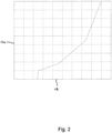
- pseudo-energy demand is plotted on x-axis 136 versus actual energy absorbed on y-axis 138 for a multitude of braking events for healthy brakes. As can be seen, there is an approximate linear relationship 140 between these two figures. Any deviation from this ideal relationship is indicative of detrimental performance of the brake.
- a histogram of brake energy differential (i.e. the difference between the actual energy absorbed and the ideal relationship 140) is plotted on the x-axis 142 with frequency on the y-axis 144. As can be seen, this follows a normal distribution having a mean of 0 and a standard deviation s.
- FIG. 9 this plot is identical to that of Figure 8 , but with a linear plot of three standard deviations 146 and four standard deviations 148 below the line 140. As can be seen, it is rare for the actual energy absorbed to drop three standard deviations below the expected value for a healthy brake (represented by line 140) and even rarer to drop four standard deviations below the line 140. The probability of the differential being over three standard deviations is 1 in 373, and over four standard deviations is 1 in 15787. As such, these values represent a suitable indicator of when a brake is malfunctioning.
- the system can be modified to produce an alert should the brake pressure differential fall outside three standard deviations more than once in a given number of braking events, thus indicating a repetitive problem with the brake. This would also eliminate false alerts from statistical anomalies.
Landscapes
- Engineering & Computer Science (AREA)
- Mechanical Engineering (AREA)
- General Engineering & Computer Science (AREA)
- Transportation (AREA)
- Aviation & Aerospace Engineering (AREA)
- Chemical & Material Sciences (AREA)
- Combustion & Propulsion (AREA)
- Regulating Braking Force (AREA)
- Valves And Accessory Devices For Braking Systems (AREA)
Claims (14)
- Verfahren zum Überwachen der Leistung einer Luftfahrzeugradbremse (112), das die folgenden Schritte umfasst:Bereitstellen eines Luftfahrzeugs, das eine Radbremse (112) aufweist,Messen von Bremsleistungseingangsgrößendaten während eines Bremsvorgangs,Berechnen eines durch die Bremse (112) über zumindest einen Teil des Bremsvorgangs aufzunehmenden Energiebedarfs unter Verwendung der Bremsleistungseingangsgrößendaten,Messen von Bremsleistungsausgangsgrößendaten während des Bremsvorgangs,Berechnen einer durch die Bremse (112) über zumindest einen Teil des Bremsvorgangs aufgenommenen Energie unter Verwendung der Bremsleistungsausgangsgrößendaten,Bestimmen einer Bremsleistungsmetrik aus dem Energiebedarf und der aufgenommenen Energie, wobei die Bremsleistungsmetrik eine Bremsenergiedifferenz ist, und wobei die Bremsenergiedifferenz eine Differenz zwischen (i) der aufgenommenen Energie und (ii) einer erwarteten aufgenommenen Energie für eine funktionsfähige Bremse (112) für den vorgegebenen Energiebedarf ist, undVergleichen der Bremsleistungsmetrik mit einem Bremsleistungskriterium, um eine beeinträchtigte Leistung der Bremse (112) zu detektieren,wobei das Bremsleistungskriterium mindestens drei Standardabweichungen einer Normalverteilung von Bremsenergiedifferenzen aus einem Verhältnis zwischen Energiebedarf und aufgenommener Energie für eine funktionsfähige Bremse (112) ist.
- Verfahren nach Anspruch 1, wobei die Bremsleistungseingangsgröße ein Bremsmomentbedarf ist.
- Verfahren nach Anspruch 1, wobei die Bremsleistungseingangsgröße ein Bremsservodruck ist.
- Verfahren nach Anspruch 3, umfassend den Schritt Umwandeln des Bremsservodrucks in einen geschätzten Bremsmomentbedarf.
- Verfahren nach Anspruch 4, wobei der geschätzte Bremsmomentbedarf ein Prozentsatz (%) eines Bremsmomentbedarfs ist.
- Verfahren nach Anspruch 4 oder 5, das die folgenden Schritte umfasst:Bereitstellen eines gebremsten Rads (114), das dazu angeordnet ist, durch die Luftfahrzeugradbremse (112) gebremst zu werden,Aufzeichnen der Drehzahl des gebremsten Rads (114) während des Bremsvorgangs,Verwenden der gebremsten Raddrehzahl, um den Energiebedarf zu berechnen.
- Verfahren nach Anspruch 6, wobei der Schritt Berechnen des Energiebedarfs die folgenden Schritte umfasst:Multiplizieren des geschätzten Bremsmomentbedarfs mit der Drehzahl des gebremsten Rads (114), um Leistungsbedarfsdaten zu berechnen,Integrieren der Leistungsbedarfsdaten über die Zeit, um den Energiebedarf zu berechnen.
- Verfahren nach einem der vorhergehenden Ansprüche, wobei die Bremsleistungsausgangsgröße ein Bremsmoment ist.
- Verfahren nach Anspruch 8, wobei das Bremsmoment an der Bremse (112) gemessen wird.
- Verfahren nach Anspruch 8 oder 9, das die folgenden Schritte umfasst:Bereitstellen eines gebremsten Rads (114), das dazu angeordnet ist, durch die Luftfahrzeugradbremse (112) gebremst zu werden,Überwachen der Drehzahl des gebremsten Rads (114) während des Bremsvorgangs,Verwenden der gebremsten Raddrehzahl, um die aufgenommene Energie zu berechnen.
- Verfahren nach Anspruch 10, wobei der Schritt Berechnen der aufgenommenen Energie die folgenden Schritte umfasst:Multiplizieren des Bremsmoments mit der Drehzahl des gebremsten Rads (114), um aufgenommene Leistungsdaten zu berechnen,Integrieren der aufgenommenen Leistungsdaten über die Zeit, um die aufgenommene Energie zu berechnen.
- Verfahren nach einem der vorhergehenden Ansprüche, das den folgenden Schritt umfasst:
Erzeugen einer Warnung, wenn eine beeinträchtigte Leistung der Bremse detektiert wird. - Einrichtung zum Überwachen einer Luftfahrzeugradbremse, die Folgendes umfasst:einen Speicher,einen ersten Sensor, der dazu angeordnet ist, Bremsleistungseingangsgrößendaten während eines Bremsvorgangs zu messen und die Bremsleistungseingangsgrößendaten an den Speicher zu senden,einen zweiten Sensor, der dazu angeordnet ist, Bremsleistungsausgangsgrößendaten während des Bremsvorgangs zu messen und die Bremsleistungsausgangsgrößendaten an den Speicher zu senden,einen Prozessor, der dazu angeordnet ist, auf den Speicher zuzugreifen, und zu Folgendem ausgelegt ist;(i) Berechnen eines durch die Bremse (112) über zumindest einen Teil eines Bremsvorgangs aufzunehmenden Energiebedarfs unter Verwendung der Bremssteuerungseingangsgrößendaten,(ii) Berechnen einer durch die Bremse (112) über zumindest einen Teil eines Bremsvorgangs aufgenommenen Energie unter Verwendung der Bremsleistungsausgangsgrößendaten,(iii) Berechnen einer Bremsleistungsmetrik aus dem Energiebedarf und der aufgenommenen Energie, wobei die Bremsleistungsmetrik eine Bremsenergiedifferenz ist, und wobei die Bremsenergiedifferenz eine Differenz zwischen (i) der aufgenommenen Energie und (ii) einer erwarteten aufgenommenen Energie für eine funktionsfähige Bremse (112) für den vorgegebenen Energiebedarf ist, und(iv) Vergleichen der Bremsleistungsmetrik mit einem Bremsleistungskriterium, um eine beeinträchtigte Leistung der Bremse (112) zu detektieren,
wobei das Bremsleistungskriterium mindestens drei Standardabweichungen einer Normalverteilung von Bremsenergiedifferenzen aus einem Verhältnis zwischen Energiebedarf und aufgenommener Energie für eine funktionsfähige Bremse (112) ist. - Einrichtung zum Überwachen einer Luftfahrzeugradbremse nach Anspruch 13, wobei der Prozessor ausgelegt ist zum (v) Erzeugen einer Warnung, wenn eine beeinträchtigte Leistung der Bremse (112) detektiert wird.
Applications Claiming Priority (1)
| Application Number | Priority Date | Filing Date | Title |
|---|---|---|---|
| GBGB1021545.7A GB201021545D0 (en) | 2010-12-21 | 2010-12-21 | A method of monitoring aircraft brake performance and apparatus for performing such a method |
Publications (3)
| Publication Number | Publication Date |
|---|---|
| EP2468596A2 EP2468596A2 (de) | 2012-06-27 |
| EP2468596A3 EP2468596A3 (de) | 2018-05-02 |
| EP2468596B1 true EP2468596B1 (de) | 2022-02-02 |
Family
ID=43598646
Family Applications (1)
| Application Number | Title | Priority Date | Filing Date |
|---|---|---|---|
| EP11193500.3A Not-in-force EP2468596B1 (de) | 2010-12-21 | 2011-12-14 | Verfahren zur Überwachung der Flugzeugbremsleistung und Vorrichtung zur Durchführung des Verfahrens |
Country Status (3)
| Country | Link |
|---|---|
| US (2) | US20120154177A1 (de) |
| EP (1) | EP2468596B1 (de) |
| GB (1) | GB201021545D0 (de) |
Cited By (1)
| Publication number | Priority date | Publication date | Assignee | Title |
|---|---|---|---|---|
| EP4393782A1 (de) | 2022-12-27 | 2024-07-03 | Airbus Defence and Space GmbH | Fehlerdiagnosesystem für ein flugzeugbremssystem |
Families Citing this family (9)
| Publication number | Priority date | Publication date | Assignee | Title |
|---|---|---|---|---|
| JP6154358B2 (ja) * | 2014-07-11 | 2017-06-28 | ファナック株式会社 | 回転テーブルを備えた工作機械 |
| GB201415364D0 (en) | 2014-08-29 | 2014-10-15 | Axscend Ltd | Method and apparatus for monitoring operation of a vehicle braking system |
| GB2549736A (en) * | 2016-04-26 | 2017-11-01 | Airbus Operations Ltd | Predicting brake cooling periods |
| GB2554097A (en) | 2016-09-20 | 2018-03-28 | Airbus Operations Ltd | Brake wear reduction apparatus |
| US10800392B2 (en) * | 2017-04-18 | 2020-10-13 | The Boeing Company | Brake health indicator systems using input and output energy |
| GB2579203B (en) * | 2018-11-23 | 2020-12-09 | Caterpillar Sarl | A method of monitoring the brake performance of a machine |
| US10882500B2 (en) * | 2018-11-30 | 2021-01-05 | Raytheon Technologies Corporation | Systems and methods for brake failure detection using retract braking |
| EP3753794B1 (de) * | 2019-06-19 | 2024-08-07 | KNORR-BREMSE Systeme für Nutzfahrzeuge GmbH | Verfahren und vorrichtung zur überwachung der bremsleistung eines fahrzeugs |
| CN120177056B (zh) * | 2025-05-22 | 2025-08-19 | 山东科大微机应用研究所有限公司 | 激光制动性能检测仪 |
Citations (1)
| Publication number | Priority date | Publication date | Assignee | Title |
|---|---|---|---|---|
| JP2008120105A (ja) * | 2006-11-08 | 2008-05-29 | Toyota Motor Corp | ブレーキ制御装置 |
Family Cites Families (25)
| Publication number | Priority date | Publication date | Assignee | Title |
|---|---|---|---|---|
| US3899916A (en) * | 1969-03-27 | 1975-08-19 | Clayton Manufacturing Co | Recorder and computer type brake analyzer and method |
| US4024756A (en) * | 1973-07-25 | 1977-05-24 | Clayton Manufacturing Company | Computer type brake analyzer |
| US4822113A (en) * | 1987-08-13 | 1989-04-18 | The Boeing Company | Braking torque control system |
| US4949021A (en) * | 1988-11-14 | 1990-08-14 | Sunstrand Corporation | Variable speed constant frequency start system with selectable input power limiting |
| US5109343A (en) * | 1990-06-06 | 1992-04-28 | Union Switch & Signal Inc. | Method and apparatus for verification of rail braking distances |
| FR2672350A1 (fr) * | 1991-02-06 | 1992-08-07 | Messier Bugatti | Dispositif de freinage controle d'un train de roues en particulier un train de roues d'avion. |
| US5390990A (en) * | 1993-11-24 | 1995-02-21 | Hydro-Aire Division Of Crane Company | Brake energy balancing system for multiple brake units |
| US5785392A (en) * | 1996-02-06 | 1998-07-28 | Westinghouse Air Brake Company | Selectable grade and uniform net shoe force braking for railway freight vehicle |
| US5833325A (en) * | 1996-02-06 | 1998-11-10 | Westinghouse Air Brake Company | Freight brake control using train net braking ratio |
| US6132016A (en) * | 1997-05-02 | 2000-10-17 | Hydro-Aire, Inc. | System and method for adaptive brake application and initial skid detection |
| US6722745B2 (en) * | 1997-05-02 | 2004-04-20 | Hydro-Aire, Inc. | System and method for adaptive brake application and initial skid detection |
| DE19911902C1 (de) * | 1999-03-17 | 2000-08-03 | Daimler Chrysler Ag | Verfahren und Vorrichtung zur variablen Einstellung der Bremskraft in einer hydraulischen Bremsanlage eines Kraftfahrzeugs |
| DE10026687B4 (de) * | 2000-05-30 | 2004-08-26 | Knorr-Bremse Systeme für Schienenfahrzeuge GmbH | Verfahren und Vorrichtung zur Wirkungsüberwachung von Fahrzeugbremsanlagen |
| US7748793B2 (en) * | 2002-05-28 | 2010-07-06 | Estop Gmbh | Fail-safe concept for an electromechanical brake |
| US6847869B2 (en) * | 2003-01-09 | 2005-01-25 | Westinghouse Air Brake Technologies Corporation | Software based brake shoe wear determination |
| US6739675B1 (en) * | 2003-01-10 | 2004-05-25 | Westinghouse Air Brake Technologies Corporation | Brake effort monitor |
| US9311676B2 (en) * | 2003-09-04 | 2016-04-12 | Hartford Fire Insurance Company | Systems and methods for analyzing sensor data |
| DE102006015034B4 (de) * | 2006-03-31 | 2010-11-18 | Continental Automotive Gmbh | Verfahren und Recheneinheit zur Bestimmung eines Leistungsparameters einer Bremse |
| US7694555B2 (en) * | 2007-03-27 | 2010-04-13 | Gm Global Technology Operations, Inc. | Brake pad prognosis system |
| FR2918637B1 (fr) * | 2007-07-09 | 2010-01-29 | Airbus France | Systeme d'egalisation des energies de freinage. |
| US8078376B2 (en) * | 2008-04-28 | 2011-12-13 | General Electric Company | System and method for verifying the availability of a level of a braking system in a powered system |
| JP2010064665A (ja) * | 2008-09-12 | 2010-03-25 | Mitsubishi Heavy Ind Ltd | 産業車両のブレーキ故障診断方法及び装置 |
| US8140206B2 (en) * | 2008-09-15 | 2012-03-20 | Caterpillar Inc. | Engine load management for traction vehicles |
| FR2941204B1 (fr) * | 2009-01-16 | 2011-02-25 | Messier Bugatti | Procede de commande d'un frein de vehicule avec correction en couple adaptative |
| FR2943037B1 (fr) * | 2009-03-11 | 2012-09-21 | Airbus France | Systeme de commande d'aeronef a architecture modulaire integre. |
-
2010
- 2010-12-21 GB GBGB1021545.7A patent/GB201021545D0/en not_active Ceased
-
2011
- 2011-02-17 US US13/029,333 patent/US20120154177A1/en not_active Abandoned
- 2011-12-14 EP EP11193500.3A patent/EP2468596B1/de not_active Not-in-force
-
2018
- 2018-03-05 US US15/912,342 patent/US20180281768A1/en not_active Abandoned
Patent Citations (1)
| Publication number | Priority date | Publication date | Assignee | Title |
|---|---|---|---|---|
| JP2008120105A (ja) * | 2006-11-08 | 2008-05-29 | Toyota Motor Corp | ブレーキ制御装置 |
Cited By (1)
| Publication number | Priority date | Publication date | Assignee | Title |
|---|---|---|---|---|
| EP4393782A1 (de) | 2022-12-27 | 2024-07-03 | Airbus Defence and Space GmbH | Fehlerdiagnosesystem für ein flugzeugbremssystem |
Also Published As
| Publication number | Publication date |
|---|---|
| EP2468596A2 (de) | 2012-06-27 |
| US20180281768A1 (en) | 2018-10-04 |
| GB201021545D0 (en) | 2011-02-02 |
| US20120154177A1 (en) | 2012-06-21 |
| EP2468596A3 (de) | 2018-05-02 |
Similar Documents
| Publication | Publication Date | Title |
|---|---|---|
| EP2468596B1 (de) | Verfahren zur Überwachung der Flugzeugbremsleistung und Vorrichtung zur Durchführung des Verfahrens | |
| US10696382B2 (en) | Fault detection based on brake torque and temperature | |
| US11136145B2 (en) | Brake temperature prediction and cooling time functionality | |
| US10882500B2 (en) | Systems and methods for brake failure detection using retract braking | |
| EP3257712B1 (de) | Systeme und verfahren zur detektion einer schleifenden bremse | |
| US10752230B2 (en) | Prognostics for pressure sensors of hydraulic brake systems | |
| US20110127828A1 (en) | Method of managing the braking of an aircraft, and a corresponding braking system | |
| US8843254B2 (en) | Systems and methods for dragging brake detection | |
| GB2571397A (en) | Vehicle braking | |
| EP3296170B1 (de) | Bremsenverschleissreduzierungsvorrichtung | |
| US11364884B2 (en) | Selective braking of carbon brakes to improve life | |
| EP2899081B1 (de) | Flugzeugbremsen-Gesundheitsüberwachungssystem und Verfahren | |
| CA2588524C (en) | Electrically actuated aircraft brakes | |
| CA2792202A1 (en) | Electronic motor actuators brake inhibit for aircraft braking system | |
| US10427664B2 (en) | Method and system for determining the effectiveness of a brake system | |
| CN113631399A (zh) | 轮胎监测 | |
| US20200317327A1 (en) | Distributed brake control systems and methods for high efficiency antiskid performance | |
| EP3659879A1 (de) | Temperaturüberwachung zur detektion des bremsenversagens | |
| US12128863B2 (en) | Detection of brake failure using wheel speed during landing gear retraction | |
| KR102200977B1 (ko) | 브레이크 제어전력 상실에 따른 항공기 착륙 사고 방지를 위한 항공기용 전자식 브레이크 시스템 | |
| Yang et al. | Abnormal detection technique for civil aircraft antiskid brake system based on LOF algorithm |
Legal Events
| Date | Code | Title | Description |
|---|---|---|---|
| AK | Designated contracting states |
Kind code of ref document: A2 Designated state(s): AL AT BE BG CH CY CZ DE DK EE ES FI FR GB GR HR HU IE IS IT LI LT LU LV MC MK MT NL NO PL PT RO RS SE SI SK SM TR |
|
| AX | Request for extension of the european patent |
Extension state: BA ME |
|
| PUAI | Public reference made under article 153(3) epc to a published international application that has entered the european phase |
Free format text: ORIGINAL CODE: 0009012 |
|
| PUAL | Search report despatched |
Free format text: ORIGINAL CODE: 0009013 |
|
| AK | Designated contracting states |
Kind code of ref document: A3 Designated state(s): AL AT BE BG CH CY CZ DE DK EE ES FI FR GB GR HR HU IE IS IT LI LT LU LV MC MK MT NL NO PL PT RO RS SE SI SK SM TR |
|
| AX | Request for extension of the european patent |
Extension state: BA ME |
|
| RIC1 | Information provided on ipc code assigned before grant |
Ipc: B60T 17/22 20060101AFI20180323BHEP Ipc: B60T 8/17 20060101ALI20180323BHEP Ipc: B64C 25/42 20060101ALI20180323BHEP |
|
| STAA | Information on the status of an ep patent application or granted ep patent |
Free format text: STATUS: REQUEST FOR EXAMINATION WAS MADE |
|
| 17P | Request for examination filed |
Effective date: 20181102 |
|
| RBV | Designated contracting states (corrected) |
Designated state(s): AL AT BE BG CH CY CZ DE DK EE ES FI FR GB GR HR HU IE IS IT LI LT LU LV MC MK MT NL NO PL PT RO RS SE SI SK SM TR |
|
| STAA | Information on the status of an ep patent application or granted ep patent |
Free format text: STATUS: EXAMINATION IS IN PROGRESS |
|
| 17Q | First examination report despatched |
Effective date: 20190506 |
|
| GRAP | Despatch of communication of intention to grant a patent |
Free format text: ORIGINAL CODE: EPIDOSNIGR1 |
|
| STAA | Information on the status of an ep patent application or granted ep patent |
Free format text: STATUS: GRANT OF PATENT IS INTENDED |
|
| INTG | Intention to grant announced |
Effective date: 20210803 |
|
| GRAS | Grant fee paid |
Free format text: ORIGINAL CODE: EPIDOSNIGR3 |
|
| GRAA | (expected) grant |
Free format text: ORIGINAL CODE: 0009210 |
|
| STAA | Information on the status of an ep patent application or granted ep patent |
Free format text: STATUS: THE PATENT HAS BEEN GRANTED |
|
| AK | Designated contracting states |
Kind code of ref document: B1 Designated state(s): AL AT BE BG CH CY CZ DE DK EE ES FI FR GB GR HR HU IE IS IT LI LT LU LV MC MK MT NL NO PL PT RO RS SE SI SK SM TR |
|
| REG | Reference to a national code |
Ref country code: GB Ref legal event code: FG4D |
|
| REG | Reference to a national code |
Ref country code: CH Ref legal event code: EP Ref country code: AT Ref legal event code: REF Ref document number: 1466512 Country of ref document: AT Kind code of ref document: T Effective date: 20220215 |
|
| REG | Reference to a national code |
Ref country code: DE Ref legal event code: R096 Ref document number: 602011072475 Country of ref document: DE |
|
| REG | Reference to a national code |
Ref country code: IE Ref legal event code: FG4D |
|
| REG | Reference to a national code |
Ref country code: LT Ref legal event code: MG9D |
|
| REG | Reference to a national code |
Ref country code: NL Ref legal event code: MP Effective date: 20220202 |
|
| REG | Reference to a national code |
Ref country code: AT Ref legal event code: MK05 Ref document number: 1466512 Country of ref document: AT Kind code of ref document: T Effective date: 20220202 |
|
| PG25 | Lapsed in a contracting state [announced via postgrant information from national office to epo] |
Ref country code: SE Free format text: LAPSE BECAUSE OF FAILURE TO SUBMIT A TRANSLATION OF THE DESCRIPTION OR TO PAY THE FEE WITHIN THE PRESCRIBED TIME-LIMIT Effective date: 20220202 Ref country code: RS Free format text: LAPSE BECAUSE OF FAILURE TO SUBMIT A TRANSLATION OF THE DESCRIPTION OR TO PAY THE FEE WITHIN THE PRESCRIBED TIME-LIMIT Effective date: 20220202 Ref country code: PT Free format text: LAPSE BECAUSE OF FAILURE TO SUBMIT A TRANSLATION OF THE DESCRIPTION OR TO PAY THE FEE WITHIN THE PRESCRIBED TIME-LIMIT Effective date: 20220602 Ref country code: NO Free format text: LAPSE BECAUSE OF FAILURE TO SUBMIT A TRANSLATION OF THE DESCRIPTION OR TO PAY THE FEE WITHIN THE PRESCRIBED TIME-LIMIT Effective date: 20220502 Ref country code: NL Free format text: LAPSE BECAUSE OF FAILURE TO SUBMIT A TRANSLATION OF THE DESCRIPTION OR TO PAY THE FEE WITHIN THE PRESCRIBED TIME-LIMIT Effective date: 20220202 Ref country code: LT Free format text: LAPSE BECAUSE OF FAILURE TO SUBMIT A TRANSLATION OF THE DESCRIPTION OR TO PAY THE FEE WITHIN THE PRESCRIBED TIME-LIMIT Effective date: 20220202 Ref country code: HR Free format text: LAPSE BECAUSE OF FAILURE TO SUBMIT A TRANSLATION OF THE DESCRIPTION OR TO PAY THE FEE WITHIN THE PRESCRIBED TIME-LIMIT Effective date: 20220202 Ref country code: ES Free format text: LAPSE BECAUSE OF FAILURE TO SUBMIT A TRANSLATION OF THE DESCRIPTION OR TO PAY THE FEE WITHIN THE PRESCRIBED TIME-LIMIT Effective date: 20220202 Ref country code: BG Free format text: LAPSE BECAUSE OF FAILURE TO SUBMIT A TRANSLATION OF THE DESCRIPTION OR TO PAY THE FEE WITHIN THE PRESCRIBED TIME-LIMIT Effective date: 20220502 |
|
| PG25 | Lapsed in a contracting state [announced via postgrant information from national office to epo] |
Ref country code: PL Free format text: LAPSE BECAUSE OF FAILURE TO SUBMIT A TRANSLATION OF THE DESCRIPTION OR TO PAY THE FEE WITHIN THE PRESCRIBED TIME-LIMIT Effective date: 20220202 Ref country code: LV Free format text: LAPSE BECAUSE OF FAILURE TO SUBMIT A TRANSLATION OF THE DESCRIPTION OR TO PAY THE FEE WITHIN THE PRESCRIBED TIME-LIMIT Effective date: 20220202 Ref country code: GR Free format text: LAPSE BECAUSE OF FAILURE TO SUBMIT A TRANSLATION OF THE DESCRIPTION OR TO PAY THE FEE WITHIN THE PRESCRIBED TIME-LIMIT Effective date: 20220503 Ref country code: FI Free format text: LAPSE BECAUSE OF FAILURE TO SUBMIT A TRANSLATION OF THE DESCRIPTION OR TO PAY THE FEE WITHIN THE PRESCRIBED TIME-LIMIT Effective date: 20220202 Ref country code: AT Free format text: LAPSE BECAUSE OF FAILURE TO SUBMIT A TRANSLATION OF THE DESCRIPTION OR TO PAY THE FEE WITHIN THE PRESCRIBED TIME-LIMIT Effective date: 20220202 |
|
| PG25 | Lapsed in a contracting state [announced via postgrant information from national office to epo] |
Ref country code: IS Free format text: LAPSE BECAUSE OF FAILURE TO SUBMIT A TRANSLATION OF THE DESCRIPTION OR TO PAY THE FEE WITHIN THE PRESCRIBED TIME-LIMIT Effective date: 20220602 |
|
| PG25 | Lapsed in a contracting state [announced via postgrant information from national office to epo] |
Ref country code: SM Free format text: LAPSE BECAUSE OF FAILURE TO SUBMIT A TRANSLATION OF THE DESCRIPTION OR TO PAY THE FEE WITHIN THE PRESCRIBED TIME-LIMIT Effective date: 20220202 Ref country code: SK Free format text: LAPSE BECAUSE OF FAILURE TO SUBMIT A TRANSLATION OF THE DESCRIPTION OR TO PAY THE FEE WITHIN THE PRESCRIBED TIME-LIMIT Effective date: 20220202 Ref country code: RO Free format text: LAPSE BECAUSE OF FAILURE TO SUBMIT A TRANSLATION OF THE DESCRIPTION OR TO PAY THE FEE WITHIN THE PRESCRIBED TIME-LIMIT Effective date: 20220202 Ref country code: EE Free format text: LAPSE BECAUSE OF FAILURE TO SUBMIT A TRANSLATION OF THE DESCRIPTION OR TO PAY THE FEE WITHIN THE PRESCRIBED TIME-LIMIT Effective date: 20220202 Ref country code: DK Free format text: LAPSE BECAUSE OF FAILURE TO SUBMIT A TRANSLATION OF THE DESCRIPTION OR TO PAY THE FEE WITHIN THE PRESCRIBED TIME-LIMIT Effective date: 20220202 Ref country code: CZ Free format text: LAPSE BECAUSE OF FAILURE TO SUBMIT A TRANSLATION OF THE DESCRIPTION OR TO PAY THE FEE WITHIN THE PRESCRIBED TIME-LIMIT Effective date: 20220202 |
|
| REG | Reference to a national code |
Ref country code: DE Ref legal event code: R097 Ref document number: 602011072475 Country of ref document: DE |
|
| PG25 | Lapsed in a contracting state [announced via postgrant information from national office to epo] |
Ref country code: AL Free format text: LAPSE BECAUSE OF FAILURE TO SUBMIT A TRANSLATION OF THE DESCRIPTION OR TO PAY THE FEE WITHIN THE PRESCRIBED TIME-LIMIT Effective date: 20220202 |
|
| PLBE | No opposition filed within time limit |
Free format text: ORIGINAL CODE: 0009261 |
|
| STAA | Information on the status of an ep patent application or granted ep patent |
Free format text: STATUS: NO OPPOSITION FILED WITHIN TIME LIMIT |
|
| 26N | No opposition filed |
Effective date: 20221103 |
|
| PG25 | Lapsed in a contracting state [announced via postgrant information from national office to epo] |
Ref country code: SI Free format text: LAPSE BECAUSE OF FAILURE TO SUBMIT A TRANSLATION OF THE DESCRIPTION OR TO PAY THE FEE WITHIN THE PRESCRIBED TIME-LIMIT Effective date: 20220202 |
|
| PG25 | Lapsed in a contracting state [announced via postgrant information from national office to epo] |
Ref country code: IT Free format text: LAPSE BECAUSE OF FAILURE TO SUBMIT A TRANSLATION OF THE DESCRIPTION OR TO PAY THE FEE WITHIN THE PRESCRIBED TIME-LIMIT Effective date: 20220202 |
|
| REG | Reference to a national code |
Ref country code: CH Ref legal event code: PL |
|
| REG | Reference to a national code |
Ref country code: BE Ref legal event code: MM Effective date: 20221231 |
|
| PG25 | Lapsed in a contracting state [announced via postgrant information from national office to epo] |
Ref country code: LU Free format text: LAPSE BECAUSE OF NON-PAYMENT OF DUE FEES Effective date: 20221214 |
|
| PG25 | Lapsed in a contracting state [announced via postgrant information from national office to epo] |
Ref country code: LI Free format text: LAPSE BECAUSE OF NON-PAYMENT OF DUE FEES Effective date: 20221231 Ref country code: IE Free format text: LAPSE BECAUSE OF NON-PAYMENT OF DUE FEES Effective date: 20221214 Ref country code: CH Free format text: LAPSE BECAUSE OF NON-PAYMENT OF DUE FEES Effective date: 20221231 |
|
| PG25 | Lapsed in a contracting state [announced via postgrant information from national office to epo] |
Ref country code: BE Free format text: LAPSE BECAUSE OF NON-PAYMENT OF DUE FEES Effective date: 20221231 |
|
| PGFP | Annual fee paid to national office [announced via postgrant information from national office to epo] |
Ref country code: GB Payment date: 20231220 Year of fee payment: 13 |
|
| PGFP | Annual fee paid to national office [announced via postgrant information from national office to epo] |
Ref country code: FR Payment date: 20231221 Year of fee payment: 13 Ref country code: DE Payment date: 20231214 Year of fee payment: 13 |
|
| PG25 | Lapsed in a contracting state [announced via postgrant information from national office to epo] |
Ref country code: HU Free format text: LAPSE BECAUSE OF FAILURE TO SUBMIT A TRANSLATION OF THE DESCRIPTION OR TO PAY THE FEE WITHIN THE PRESCRIBED TIME-LIMIT; INVALID AB INITIO Effective date: 20111214 |
|
| PG25 | Lapsed in a contracting state [announced via postgrant information from national office to epo] |
Ref country code: CY Free format text: LAPSE BECAUSE OF FAILURE TO SUBMIT A TRANSLATION OF THE DESCRIPTION OR TO PAY THE FEE WITHIN THE PRESCRIBED TIME-LIMIT Effective date: 20220202 |
|
| PG25 | Lapsed in a contracting state [announced via postgrant information from national office to epo] |
Ref country code: MK Free format text: LAPSE BECAUSE OF FAILURE TO SUBMIT A TRANSLATION OF THE DESCRIPTION OR TO PAY THE FEE WITHIN THE PRESCRIBED TIME-LIMIT Effective date: 20220202 |
|
| PG25 | Lapsed in a contracting state [announced via postgrant information from national office to epo] |
Ref country code: MC Free format text: LAPSE BECAUSE OF FAILURE TO SUBMIT A TRANSLATION OF THE DESCRIPTION OR TO PAY THE FEE WITHIN THE PRESCRIBED TIME-LIMIT Effective date: 20220202 |
|
| PG25 | Lapsed in a contracting state [announced via postgrant information from national office to epo] |
Ref country code: TR Free format text: LAPSE BECAUSE OF FAILURE TO SUBMIT A TRANSLATION OF THE DESCRIPTION OR TO PAY THE FEE WITHIN THE PRESCRIBED TIME-LIMIT Effective date: 20220202 Ref country code: MC Free format text: LAPSE BECAUSE OF FAILURE TO SUBMIT A TRANSLATION OF THE DESCRIPTION OR TO PAY THE FEE WITHIN THE PRESCRIBED TIME-LIMIT Effective date: 20220202 |
|
| PG25 | Lapsed in a contracting state [announced via postgrant information from national office to epo] |
Ref country code: MT Free format text: LAPSE BECAUSE OF FAILURE TO SUBMIT A TRANSLATION OF THE DESCRIPTION OR TO PAY THE FEE WITHIN THE PRESCRIBED TIME-LIMIT Effective date: 20220202 |
|
| REG | Reference to a national code |
Ref country code: DE Ref legal event code: R119 Ref document number: 602011072475 Country of ref document: DE |
|
| GBPC | Gb: european patent ceased through non-payment of renewal fee |
Effective date: 20241214 |
|
| PG25 | Lapsed in a contracting state [announced via postgrant information from national office to epo] |
Ref country code: DE Free format text: LAPSE BECAUSE OF NON-PAYMENT OF DUE FEES Effective date: 20250701 |
|
| PG25 | Lapsed in a contracting state [announced via postgrant information from national office to epo] |
Ref country code: GB Free format text: LAPSE BECAUSE OF NON-PAYMENT OF DUE FEES Effective date: 20241214 |
|
| PG25 | Lapsed in a contracting state [announced via postgrant information from national office to epo] |
Ref country code: FR Free format text: LAPSE BECAUSE OF NON-PAYMENT OF DUE FEES Effective date: 20241231 |