EP2468580A1 - Interior material mounting structure - Google Patents
Interior material mounting structure Download PDFInfo
- Publication number
- EP2468580A1 EP2468580A1 EP20110195072 EP11195072A EP2468580A1 EP 2468580 A1 EP2468580 A1 EP 2468580A1 EP 20110195072 EP20110195072 EP 20110195072 EP 11195072 A EP11195072 A EP 11195072A EP 2468580 A1 EP2468580 A1 EP 2468580A1
- Authority
- EP
- European Patent Office
- Prior art keywords
- interior material
- end portion
- front pillar
- projecting piece
- car body
- Prior art date
- Legal status (The legal status is an assumption and is not a legal conclusion. Google has not performed a legal analysis and makes no representation as to the accuracy of the status listed.)
- Granted
Links
Images


Classifications
-
- B—PERFORMING OPERATIONS; TRANSPORTING
- B60—VEHICLES IN GENERAL
- B60R—VEHICLES, VEHICLE FITTINGS, OR VEHICLE PARTS, NOT OTHERWISE PROVIDED FOR
- B60R13/00—Elements for body-finishing, identifying, or decorating; Arrangements or adaptations for advertising purposes
- B60R13/02—Internal Trim mouldings ; Internal Ledges; Wall liners for passenger compartments; Roof liners
- B60R13/0206—Arrangements of fasteners and clips specially adapted for attaching inner vehicle liners or mouldings
-
- B—PERFORMING OPERATIONS; TRANSPORTING
- B60—VEHICLES IN GENERAL
- B60R—VEHICLES, VEHICLE FITTINGS, OR VEHICLE PARTS, NOT OTHERWISE PROVIDED FOR
- B60R13/00—Elements for body-finishing, identifying, or decorating; Arrangements or adaptations for advertising purposes
- B60R13/02—Internal Trim mouldings ; Internal Ledges; Wall liners for passenger compartments; Roof liners
- B60R13/0212—Roof or head liners
-
- B—PERFORMING OPERATIONS; TRANSPORTING
- B60—VEHICLES IN GENERAL
- B60R—VEHICLES, VEHICLE FITTINGS, OR VEHICLE PARTS, NOT OTHERWISE PROVIDED FOR
- B60R13/00—Elements for body-finishing, identifying, or decorating; Arrangements or adaptations for advertising purposes
- B60R13/02—Internal Trim mouldings ; Internal Ledges; Wall liners for passenger compartments; Roof liners
- B60R13/0237—Side or rear panels
- B60R13/025—Pillars; Roof rails
-
- B—PERFORMING OPERATIONS; TRANSPORTING
- B60—VEHICLES IN GENERAL
- B60R—VEHICLES, VEHICLE FITTINGS, OR VEHICLE PARTS, NOT OTHERWISE PROVIDED FOR
- B60R13/00—Elements for body-finishing, identifying, or decorating; Arrangements or adaptations for advertising purposes
- B60R13/02—Internal Trim mouldings ; Internal Ledges; Wall liners for passenger compartments; Roof liners
- B60R2013/0293—Connection or positioning of adjacent panels
Definitions
- the present invention relates to an interior material mounting structure. More particularly, the present invention relates to an interior material mounting structure having: a car body panel; an upper interior material and a lower interior material mounted on the car body panel, with their end portions being connected to each other; and a rope-like body disposed from a space between the upper interior material and the car body panel to a space between the lower interior material and the car body panel.
- Some automobile is provided with a car body panel, and an upper interior material and a lower interior material mounted on the car body panel. An end portion of the upper interior material and an end portion of the lower interior material are connected to each other.
- the present invention was made in consideration of the above circumstances and has an object to provide an interior material mounting structure capable of improving outer appearance of a parting portion between an end portion of an upper interior material and an end portion of a lower interior material and simplifying shaping molds of the interior materials to reduce manufacturing cost of the shaping molds.
- the present invention is an interior material mounting structure in which an upper interior material and a lower interior material are mounted on a car body panel, an end portion of the upper interior material and an end portion of the lower interior material are connected to each other, and a rope-like body is disposed from a space between the lower interior material and the car body panel to a space between the upper interior material and the car body panel, the structure including a projecting piece provided on the end portion of at least one interior material out of the upper interior material and the lower interior material to project toward the car body panel, wherein the rope-like body is disposed to keep clear of the projecting piece.
- the projecting piece is provided on the end portion of the upper interior material, and a clip hole for a clip fixing the end portion of the lower interior material to the car body panel is formed in the car body panel below the projecting piece.
- a projection end portion of the projecting piece abuts on the car body panel.
- a convex portion formed on the projecting piece is fitted in a concave portion formed in the car body panel.
- the upper interior material is a roof lining
- the lower interior material is a front pillar trim
- the rope-like body is a tether belt of a head protection airbag.
- a front pillar 3 is disposed between a front window glass 1 and a front door 2 of a car 100.
- An upper end portion of the front pillar 3 is connected to a front corner C of a roof 4.
- 42 denotes an instrument panel
- 40 denotes a front seat
- 41 denotes a rear seat.
- the front pillar 3 includes: a front pillar inner panel 6 corresponding to a car body panel; and a front pillar trim 7 of resin corresponding to a lower interior material.
- the front pillar trim 7 is mounted on the front pillar inner panel 6 to cover a surface, of the front pillar inner panel 6, on a cabin inner side.
- the roof 4 includes a roof panel 18 corresponding to the car body panel and a roof lining 8 of resin corresponding to an upper interior material.
- the roof lining 8 is mounted on the roof panel 18 to cover the roof panel 18.
- the roof lining 8 is formed in a rectangular shape which is long in a front and rear direction of the car 100 in a top view. From the front corner C of the roof lining 8, a connection part 9 connected to the front pillar trim 7 extends downward. Both side portions of the connection part 9 in terms of the front and rear direction of the car 100 are bent toward the outside of the cabin. Bent portions are a front sidewall 10 and a rear sidewall 11. That is, the front sidewall 10 and the rear sidewall 11 (see Fig. 3 and Fig. 4 ) are formed on the connection part 9.
- a sun visor 14 is mounted on a front end portion of the roof 4.
- both side portions of the front pillar trim 7 in terms of the front and rear direction of the car 100 are bent toward the outside of the cabin. Bent portions are a front sidewall 12 and a rear sidewall 13.
- an upper end portion 7J of the front pillar trim 7 (this upper end portion 7J corresponds to an end portion of the lower interior material) and a lower end portion 9K of the connection part 9 of the roof lining 8 (this lower end portion 9K corresponds to an end portion of the upper interior material) are laid on each other in a car width direction to be connected to each other. Consequently, a parting line L is formed along a joint portion of the upper end portion 7J of the front pillar trim 7 and the lower end portion 9K of the connection part 9 of the roof lining 8 (see Fig. 3 ) .
- a washer hose feeder line 20 and a tether belt 21 of a curtain airbag each corresponding to a rope-like body are disposed from a space between the front pillar trim 7 and the front pillar inner panel 6 (that is, the inside of the front pillar 3) to a space between the roof lining 8 and the roof panel 18 (that is, the inside of the roof 4).
- the washer hose feeder line 20 passes through the inside of the front pillar 3 and a right side portion of the roof 4 and thus extends from a downward position of the front pillar 3 to a rear side Rr of the car 100.
- This washer hose feeder line 20 is fixed to the front pillar inner panel 6 via clamps 43 (see Fig. 4 ).
- the washer hose feeder line 20 feeds a washing liquid to washing liquid injection nozzles for the front window glass 1 and a back window glass 43 (see Fig. 2 ).
- the tether belt 21 of the curtain airbag corresponding to a head protection airbag extends from a front end portion of a bag main body of the curtain airbag.
- a bracket 48 at a tip portion side of the tether belt 21 is fastened to a widthwise center portion of the front pillar inner panel 6 by a screw S (see Fig. 4 ).
- the bag main body Upon side collision, the bag main body is fed with gas from an inflator to be inflated and deployed downward, and the tether belt 21 is drawn out to the cabin inner side from a reverse side of the front pillar trim 7 while pulled to the rear side Rr of the car 100 by the bag main body. Consequently, the tether belt 21 is located at a positioning and acting position to hold a position of a lower end portion of the bag main body, and the bag main body inflated and deployed in a predetermined shape protects the head of a passenger.
- a projecting piece 15 is integrally provided on a reverse surface of the lower end portion 9K of the connection part 9 of the roof lining 8.
- the projecting piece 15 has a trapezoidal structure in a top view and projects toward the front pillar inner panel 6.
- the washer hose feeder line 20 is disposed along a side portion, of the front pillar inner panel 6, located more on the front side Fr of the car 100 than the projecting piece 15 so as to be keep clear of the projecting piece 15.
- the tether belt 21 is disposed along a side portion, of the front pillar inner panel 6, located more on the rear side Rr of the car 100 than the projecting piece 15 so as to keep clear of the projecting piece 15 (see Fig. 4 ).
- a projection end portion 15T of the projecting piece 15 abuts on the front pillar inner panel 6.
- a gap between the front pillar inner panel 6 and the lower end portion 9K of the connection part 9 of the roof lining 8 is narrower on the rear side Rr of the car 100.
- a concave portion 6U is formed in the front pillar inner panel 6, and a convex portion 15C formed on the projecting piece 15 is fitted in the concave portion 6U.
- a rib 47 continuing to a base portion of the projecting piece 15 is projectingly provided along substantially the whole width of the lower end portion 9K of the connection part 9. This enables improvement in rigidity and strength of the projecting piece 15 to improve durability of the projecting piece 15.
- the reference 31 in Fig. 5 denotes a front door opening trim.
- a clip hole 16 is formed in the front pillar inner panel 6 below the projecting piece 15.
- the projecting piece 15 is in proximity to the clip hole 16 in an up and down direction.
- This clip hole 16 is a hole in which a clip 19 fixing the upper end portion 7J of the front pillar trim 7 to the front pillar inner panel 6 is fitted.
- a clip seat 17 having a trapezoidal cross section bulging toward the front pillar inner panel 6 is formed on the upper end portion 7J of the front pillar trim 7, and the clip 19 projects from a seat surface 17J of the clip seat 17.
- the curtain airbag is first mounted on the car body panel such as the front pillar inner panel 6. Thereafter, the roof lining 8 is mounted on the roof panel 18, and thereafter the front pillar trim 7 is mounted on the front pillar inner panel 6.
- This position restriction can prevent the lower end portion 9K of the connection part 9 of the roof lining 8 and the upper end portion 7J of the front pillar trim 7 from riding on the washer hose feeder line 20 and the tether belt 21. Accordingly, it is possible to prevent a gap from occurring at the parting portion between the lower end portion 9K of the connection part 9 of the roof lining 8 and the upper end portion 7J of the front pillar trim 7. This enables improvement in quality of outer appearance of the parting portion.
- the projecting piece 15 projecting toward the front pillar inner panel 6 only needs to be provided on the lower end portion 9K of the connection part 9 of the roof lining 8. This can simplify shaping molds of the roof lining 8 and the front pillar trim 7. Accordingly, it is possible to reduce manufacturing cost of the shaping molds.
- the projecting piece 15 projecting toward the front pillar inner panel 6 is provided on the lower end portion 9K of the connection part 9 of the roof lining 8, and the tether belt 21 is disposed to keep clear of the projecting piece 15. Consequently, the projecting piece 15 is capable of restricting the position of the tether belt 21. Therefore, it is possible to prevent the clip 19 from obstructing the smooth deployment of the airbag.
- an interior material mounting structure capable of improving outer appearance of a parting portion between an end portion of an upper interior material and an end portion of a lower interior material and simplifying shaping molds of the interior materials to reduce manufacturing cost of the shaping molds.
- the projecting piece projecting toward the car body panel is provided on the end portion of at least one interior material out of the upper interior material and the lower interior material, and the rope-like body is disposed to keep clear of the projecting piece, which enables the position restriction of the rope-like body by the projecting piece.
- This position restriction can prevent the end portion of the upper interior material and the end portion of the lower interior material from riding on the rope-like body and can prevent a gap from occurring at the parting portion between the end portion of the upper interior material and the end portion of the lower interior material, enabling improvement in the outer appearance of the parting portion.
- the projecting piece projecting toward the car body panel only needs to be provided on the end portion of at least one of the interior materials, which can simplify shaping molds of the interior materials to reduce manufacturing cost of the shaping molds.
- the projecting piece is capable of the position restriction of the rope-like body, which can prevent the rope-like body from getting caught between the clip and the clip hole when the end portion of the lower interior material is fixed to the car body panel.
- the present invention even if a force pressing the upper interior material (or the lower interior material) toward the outside of the cabin is generated when, for example, the lower interior material (or the upper interior material) is mounted on the car body panel, it is possible to prevent the end portion of the lower interior material (or the upper interior material) from bending, owing to the projecting piece abutting on the car body panel, which can prevent a problem that a gap is formed at the parting portion between the end portion of the lower interior material and the end portion of the upper interior material.
- the convex portion formed on the projecting piece is fitted in the concave portion formed in the car body panel, it is possible to prevent the positional displacement of the upper interior material with respect to the car body panel.
- the projecting piece projecting toward the car body panel is provided on the end portion of at least one of the roof lining and the front pillar trim, and the tether belt of the head protection airbag is disposed to keep clear of the projecting piece. Accordingly, the projecting piece is capable of the position restriction of the tether belt of the head protection airbag, which can prevent the clip from obstructing the smooth deployment of the airbag.
- an interior material mounting structure capable of improving outer appearance of a parting portion between an end portion of an upper interior material and an end portion of a lower interior material, and capable of simplifying molds of the interior materials to reduce manufacturing cost of the molds.
Landscapes
- Engineering & Computer Science (AREA)
- Mechanical Engineering (AREA)
- Vehicle Interior And Exterior Ornaments, Soundproofing, And Insulation (AREA)
- Air Bags (AREA)
Abstract
Description
- This application is based upon and claims the benefit of priority of the prior Japanese Patent Application No.
2010-290826, filed on December 27, 2010 - The present invention relates to an interior material mounting structure. More particularly, the present invention relates to an interior material mounting structure having: a car body panel; an upper interior material and a lower interior material mounted on the car body panel, with their end portions being connected to each other; and a rope-like body disposed from a space between the upper interior material and the car body panel to a space between the lower interior material and the car body panel.
- Some automobile is provided with a car body panel, and an upper interior material and a lower interior material mounted on the car body panel. An end portion of the upper interior material and an end portion of the lower interior material are connected to each other.
- In such an interior material mounting structure, various kinds of rope-like bodies such as a drain hose are sometimes disposed from a space between the lower interior material and the car body panel to a space between the upper interior material and the car body panel.
- When the end portion of the upper interior material or the end portion of the lower interior material rides on the rope-like bodies, a gap occurs at a parting portion between the end portion of the upper interior material and the end portion of the lower interior material, which has a problem of impairing outer appearance of the parting portion.
- Therefore, there have conventionally been used a structure to form a plurality of restricting pieces restricting arrangement paths of rope-like bodies over a long range and a structure to form paths of rope-like bodies in the interior materials as disclosed in
Patent Document 1 andPatent Document 2. - [Patent Document 1] Japanese Laid-open Patent Publication No.
11-34755 - [Patent Document 2] Japanese Laid-open Patent Publication No.
11-98658 - However, according to the above-described conventional structures, because of a need to form the plural restricting pieces or the paths of the rope-like bodies, the structure of shaping molds of the interior materials are complicated, causing an increase in cost of the shaping molds.
- The present invention was made in consideration of the above circumstances and has an object to provide an interior material mounting structure capable of improving outer appearance of a parting portion between an end portion of an upper interior material and an end portion of a lower interior material and simplifying shaping molds of the interior materials to reduce manufacturing cost of the shaping molds.
- In order to solve the aforesaid problem, the present invention is an interior material mounting structure in which an upper interior material and a lower interior material are mounted on a car body panel, an end portion of the upper interior material and an end portion of the lower interior material are connected to each other, and a rope-like body is disposed from a space between the lower interior material and the car body panel to a space between the upper interior material and the car body panel, the structure including a projecting piece provided on the end portion of at least one interior material out of the upper interior material and the lower interior material to project toward the car body panel, wherein the rope-like body is disposed to keep clear of the projecting piece.
- In the present invention, the projecting piece is provided on the end portion of the upper interior material, and a clip hole for a clip fixing the end portion of the lower interior material to the car body panel is formed in the car body panel below the projecting piece.
- In the present invention, a projection end portion of the projecting piece abuts on the car body panel.
- In the present invention, a convex portion formed on the projecting piece is fitted in a concave portion formed in the car body panel.
- In the present invention, the upper interior material is a roof lining, the lower interior material is a front pillar trim, and the rope-like body is a tether belt of a head protection airbag.
-
-
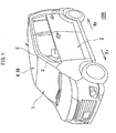
Fig. 1 is a perspective view of a car. -
Fig. 2 is a perspective view of the inside of a cabin of the car. -
Fig. 3 is a perspective view illustrating a connection part between a roof lining and a front pillar trim. -
Fig. 4 is a perspective view of a front pillar, with a front pillar trim being removed. -
Fig. 5 is a cross-sectional view taken along the V-V line inFig. 4 . -
Fig. 6 is a view illustrating a comparative example and is a view corresponding to the V-V section inFig. 4 . - Hereinafter, an embodiment of the present invention will be described based on the drawings.
- As illustrated in
Fig. 1 andFig. 2 , afront pillar 3 is disposed between afront window glass 1 and afront door 2 of acar 100. An upper end portion of thefront pillar 3 is connected to a front corner C of a roof 4. InFig. 2 , 42 denotes an instrument panel, 40 denotes a front seat, and 41 denotes a rear seat. - As illustrated in
Fig. 3 andFig. 4 , thefront pillar 3 includes: a front pillarinner panel 6 corresponding to a car body panel; and afront pillar trim 7 of resin corresponding to a lower interior material. Thefront pillar trim 7 is mounted on the front pillarinner panel 6 to cover a surface, of the front pillarinner panel 6, on a cabin inner side. The roof 4 includes a roof panel 18 corresponding to the car body panel and a roof lining 8 of resin corresponding to an upper interior material. The roof lining 8 is mounted on the roof panel 18 to cover the roof panel 18. - The roof lining 8 is formed in a rectangular shape which is long in a front and rear direction of the
car 100 in a top view. From the front corner C of the roof lining 8, aconnection part 9 connected to thefront pillar trim 7 extends downward. Both side portions of theconnection part 9 in terms of the front and rear direction of thecar 100 are bent toward the outside of the cabin. Bent portions are afront sidewall 10 and arear sidewall 11. That is, thefront sidewall 10 and the rear sidewall 11 (seeFig. 3 andFig. 4 ) are formed on theconnection part 9. Asun visor 14 is mounted on a front end portion of the roof 4. - As illustrated in
Fig. 5 , both side portions of thefront pillar trim 7 in terms of the front and rear direction of thecar 100 are bent toward the outside of the cabin. Bent portions are afront sidewall 12 and arear sidewall 13. As illustrated inFig. 3 andFig. 4 , anupper end portion 7J of the front pillar trim 7 (thisupper end portion 7J corresponds to an end portion of the lower interior material) and alower end portion 9K of theconnection part 9 of the roof lining 8 (thislower end portion 9K corresponds to an end portion of the upper interior material) are laid on each other in a car width direction to be connected to each other. Consequently, a parting line L is formed along a joint portion of theupper end portion 7J of thefront pillar trim 7 and thelower end portion 9K of theconnection part 9 of the roof lining 8 (seeFig. 3 ) . - Further, a washer
hose feeder line 20 and atether belt 21 of a curtain airbag each corresponding to a rope-like body are disposed from a space between thefront pillar trim 7 and the front pillar inner panel 6 (that is, the inside of the front pillar 3) to a space between the roof lining 8 and the roof panel 18 (that is, the inside of the roof 4). - The washer
hose feeder line 20 passes through the inside of thefront pillar 3 and a right side portion of the roof 4 and thus extends from a downward position of thefront pillar 3 to a rear side Rr of thecar 100. This washerhose feeder line 20 is fixed to the front pillarinner panel 6 via clamps 43 (seeFig. 4 ). The washerhose feeder line 20 feeds a washing liquid to washing liquid injection nozzles for thefront window glass 1 and a back window glass 43 (seeFig. 2 ). - The
tether belt 21 of the curtain airbag corresponding to a head protection airbag extends from a front end portion of a bag main body of the curtain airbag. Abracket 48 at a tip portion side of thetether belt 21 is fastened to a widthwise center portion of the front pillarinner panel 6 by a screw S (seeFig. 4 ). - Upon side collision, the bag main body is fed with gas from an inflator to be inflated and deployed downward, and the
tether belt 21 is drawn out to the cabin inner side from a reverse side of thefront pillar trim 7 while pulled to the rear side Rr of thecar 100 by the bag main body. Consequently, thetether belt 21 is located at a positioning and acting position to hold a position of a lower end portion of the bag main body, and the bag main body inflated and deployed in a predetermined shape protects the head of a passenger. - As illustrated in
Fig. 4 andFig. 5 , on a reverse surface of thelower end portion 9K of theconnection part 9 of the roof lining 8, aprojecting piece 15 is integrally provided. The projectingpiece 15 has a trapezoidal structure in a top view and projects toward the front pillarinner panel 6. The washerhose feeder line 20 is disposed along a side portion, of the front pillarinner panel 6, located more on the front side Fr of thecar 100 than the projectingpiece 15 so as to be keep clear of the projectingpiece 15. Further, thetether belt 21 is disposed along a side portion, of the front pillarinner panel 6, located more on the rear side Rr of thecar 100 than the projectingpiece 15 so as to keep clear of the projecting piece 15 (seeFig. 4 ). - On the reverse surface of the
lower end portion 9K of theconnection part 9 of the roof lining 8, the projectingpiece 15 is located at a center portion in terms of a width direction of thelower end portion 9K of the connection part 9 (= the front and rear direction of the car 100). Further, both plate surfaces of the projectingpiece 15 face a longitudinal direction of the washerhose feeder line 20 and the tether belt 21 (that is, a longitudinal direction of the front pillar trim 7). - A
projection end portion 15T of the projectingpiece 15 abuts on the front pillarinner panel 6. A gap between the front pillarinner panel 6 and thelower end portion 9K of theconnection part 9 of the roof lining 8 is narrower on the rear side Rr of thecar 100. - Further, a
concave portion 6U is formed in the front pillarinner panel 6, and a convex portion 15C formed on the projectingpiece 15 is fitted in theconcave portion 6U. Theconcave portion 6U and the convex portion 15C are each formed in an arc shape in a top view. This can prevent thelower end portion 9K of theconnection part 9 of the roof lining 8 from displacing in a width direction of the front pillar 3 (= the front and rear direction of the car 100) with respect to the front pillarinner panel 6. - As illustrated in
Fig. 4 andFig. 5 , on the reverse surface of thelower end portion 9K of theconnection part 9 of the roof lining 8, arib 47 continuing to a base portion of the projectingpiece 15 is projectingly provided along substantially the whole width of thelower end portion 9K of theconnection part 9. This enables improvement in rigidity and strength of the projectingpiece 15 to improve durability of the projectingpiece 15. Thereference 31 inFig. 5 denotes a front door opening trim. - Further, as illustrated in
Fig. 3 to Fig. 5 , aclip hole 16 is formed in the front pillarinner panel 6 below the projectingpiece 15. The projectingpiece 15 is in proximity to theclip hole 16 in an up and down direction. Thisclip hole 16 is a hole in which aclip 19 fixing theupper end portion 7J of the front pillar trim 7 to the front pillarinner panel 6 is fitted. - As illustrated in
Fig. 5 , aclip seat 17 having a trapezoidal cross section bulging toward the front pillarinner panel 6 is formed on theupper end portion 7J of thefront pillar trim 7, and theclip 19 projects from aseat surface 17J of theclip seat 17. - In the assembly of the
car 100, the curtain airbag is first mounted on the car body panel such as the front pillarinner panel 6. Thereafter, the roof lining 8 is mounted on the roof panel 18, and thereafter the front pillar trim 7 is mounted on the front pillarinner panel 6. - According to the above-described structure, the following effects are exhibited.
- (1) The projecting
piece 15 projecting toward the front pillarinner panel 6 is provided on thelower end portion 9K of theconnection part 9 of the roof lining 8. The washerhose feeder line 20 and thetether belt 21 are disposed to keep clear of the projectingpiece 15. Therefore, the projectingpiece 15 restricts the positions of the washerhose feeder line 20 and thetether belt 21. - This position restriction can prevent the
lower end portion 9K of theconnection part 9 of the roof lining 8 and theupper end portion 7J of the front pillar trim 7 from riding on the washerhose feeder line 20 and thetether belt 21. Accordingly, it is possible to prevent a gap from occurring at the parting portion between thelower end portion 9K of theconnection part 9 of the roof lining 8 and theupper end portion 7J of thefront pillar trim 7. This enables improvement in quality of outer appearance of the parting portion. - Further, as a means for the position restriction, the projecting
piece 15 projecting toward the front pillarinner panel 6 only needs to be provided on thelower end portion 9K of theconnection part 9 of the roof lining 8. This can simplify shaping molds of the roof lining 8 and thefront pillar trim 7. Accordingly, it is possible to reduce manufacturing cost of the shaping molds. - (2) The
clip hole 16 for theclip 19 fixing theupper end portion 7J of the front pillar trim 7 to the front pillarinner panel 6 is formed in the front pillarinner panel 6 below the projectingpiece 15. This can prevent the washerhose feeder line 20 and thetether belt 21 from getting caught between theclip 19 and theclip hole 16 when thelower end portion 9K of theconnection part 9 of the roof lining 8 is fixed to the front pillarinner panel 6. - (3) For example, when the front pillar trim 7 is mounted on the front pillar
inner panel 6, a force pressing the roof lining 8 toward the outside of the cabin is sometimes generated. Even in such a case, the projectingpiece 15 abutting on the front pillarinner panel 6 makes it possible to prevent thelower end portion 9K of theconnection part 9 of the roof lining 8 from bending. Therefore, it is possible to prevent a gap from occurring at the parting portion between the end portion of the front pillar trim 7 and the end portion of the roof lining 8. - (4) In a comparative example illustrated in
Fig. 6 , thetether belt 21 is sometimes disposed, for example, more on the front side Fr of thecar 100 than theclip 19 instead of being disposed along the proper place. In such a case, in the structure of the comparative example, when the curtain airbag is deployed, thetether belt 21 is pulled in an arrow A direction (the rear side Rr of the car 100) and is liable to be hooked on theclip 19. - On the other hand, according to the structure of the embodiment of the present invention, the projecting
piece 15 projecting toward the front pillarinner panel 6 is provided on thelower end portion 9K of theconnection part 9 of the roof lining 8, and thetether belt 21 is disposed to keep clear of the projectingpiece 15. Consequently, the projectingpiece 15 is capable of restricting the position of thetether belt 21. Therefore, it is possible to prevent theclip 19 from obstructing the smooth deployment of the airbag. -
- (1) Instead of the above-described structure or in addition to the above-described structure, the projecting
piece 15 may be provided on a reverse surface of theupper end portion 7J of the front pillar trim 7 so as to project toward the front pillarinner panel 6. The point is that the projectingpiece 15 only needs to be provided on at least one of the roof lining 8 as the upper interior material and the front pillar trim 7 as the lower interior material. - (2) The rope-like body may be a rope-like body other than the washer
hose feeder line 20 and thetether belt 21. The point is that the rope-like body may be any, provided that it is disposed from the space between the front pillar trim 7 and the front pillarinner panel 6 to the space between the roof lining 8 and the roof panel 18. - According to the present invention, it is possible to provide an interior material mounting structure capable of improving outer appearance of a parting portion between an end portion of an upper interior material and an end portion of a lower interior material and simplifying shaping molds of the interior materials to reduce manufacturing cost of the shaping molds.
- According to the present invention, the projecting piece projecting toward the car body panel is provided on the end portion of at least one interior material out of the upper interior material and the lower interior material, and the rope-like body is disposed to keep clear of the projecting piece, which enables the position restriction of the rope-like body by the projecting piece. This position restriction can prevent the end portion of the upper interior material and the end portion of the lower interior material from riding on the rope-like body and can prevent a gap from occurring at the parting portion between the end portion of the upper interior material and the end portion of the lower interior material, enabling improvement in the outer appearance of the parting portion. As a means for the position restriction, the projecting piece projecting toward the car body panel only needs to be provided on the end portion of at least one of the interior materials, which can simplify shaping molds of the interior materials to reduce manufacturing cost of the shaping molds.
- According to the present invention, the projecting piece is capable of the position restriction of the rope-like body, which can prevent the rope-like body from getting caught between the clip and the clip hole when the end portion of the lower interior material is fixed to the car body panel.
- According to the present invention, even if a force pressing the upper interior material (or the lower interior material) toward the outside of the cabin is generated when, for example, the lower interior material (or the upper interior material) is mounted on the car body panel, it is possible to prevent the end portion of the lower interior material (or the upper interior material) from bending, owing to the projecting piece abutting on the car body panel, which can prevent a problem that a gap is formed at the parting portion between the end portion of the lower interior material and the end portion of the upper interior material.
- According to the present invention, since the convex portion formed on the projecting piece is fitted in the concave portion formed in the car body panel, it is possible to prevent the positional displacement of the upper interior material with respect to the car body panel.
- If the tether belt is not disposed along the proper place, there is a possibility that the tether belt might be hooked on the clip when the curtain airbag is deployed. On the other hand, according to the present invention, the projecting piece projecting toward the car body panel is provided on the end portion of at least one of the roof lining and the front pillar trim, and the tether belt of the head protection airbag is disposed to keep clear of the projecting piece. Accordingly, the projecting piece is capable of the position restriction of the tether belt of the head protection airbag, which can prevent the clip from obstructing the smooth deployment of the airbag.
- It should be noted that the above embodiments merely illustrate concrete examples of implementing the present invention, and the technical scope of the present invention is not to be construed in a restrictive manner by these embodiments. That is, the present invention may be implemented in various forms without departing from the technical spirit or main features thereof.
- According to the present invention, it is possible to provide an interior material mounting structure capable of improving outer appearance of a parting portion between an end portion of an upper interior material and an end portion of a lower interior material, and capable of simplifying molds of the interior materials to reduce manufacturing cost of the molds.
Claims (5)
- An interior material mounting structure in which
an upper interior material and a lower interior material are mounted on a car body panel,
an end portion of the upper interior material and an end portion of the lower interior material are connected to each other, and
a rope-like body is disposed from a space between the lower interior material and the car body panel to a space between the upper interior material and the car body panel, the structure comprising
a projecting piece provided on the end portion of at least one interior material out of the upper interior material and the lower interior material to project toward the car body panel,
wherein the rope-like body is disposed to keep clear of the projecting piece. - The interior material mounting structure according to claim 1,
wherein the projecting piece is provided on the end portion of the upper interior material, and
wherein a clip hole for a clip fixing the end portion of the lower interior material to the car body panel is formed in the car body panel below the projecting piece. - The interior material mounting structure according to claim 1, wherein a projection end portion of the projecting piece abuts on the car body panel.
- The interior material mounting structure according to claim 3, wherein a convex portion formed on the projection end portion of the projecting piece is fitted in a concave portion formed in the car body panel.
- The interior material mounting structure according to claim 1,
wherein the upper interior material is a roof lining,
wherein the lower interior material is a front pillar trim, and
wherein the rope-like body is a tether belt of a head protection airbag.
Applications Claiming Priority (1)
| Application Number | Priority Date | Filing Date | Title |
|---|---|---|---|
| JP2010290826A JP5765663B2 (en) | 2010-12-27 | 2010-12-27 | Interior material mounting structure |
Publications (2)
| Publication Number | Publication Date |
|---|---|
| EP2468580A1 true EP2468580A1 (en) | 2012-06-27 |
| EP2468580B1 EP2468580B1 (en) | 2015-07-29 |
Family
ID=45444448
Family Applications (1)
| Application Number | Title | Priority Date | Filing Date |
|---|---|---|---|
| EP11195072.1A Active EP2468580B1 (en) | 2010-12-27 | 2011-12-22 | Interior material mounting structure |
Country Status (3)
| Country | Link |
|---|---|
| US (1) | US8955895B2 (en) |
| EP (1) | EP2468580B1 (en) |
| JP (1) | JP5765663B2 (en) |
Families Citing this family (7)
| Publication number | Priority date | Publication date | Assignee | Title |
|---|---|---|---|---|
| US8534744B2 (en) * | 2011-09-01 | 2013-09-17 | Toyota Motor Engineering & Manufacturing North America, Inc. | Pillar garnishments, interior garnishment assemblies incorporating the same, and methods for controlling alignment of interior garnishment assemblies |
| JP5971075B2 (en) * | 2012-10-16 | 2016-08-17 | マツダ株式会社 | Automobile front pillar structure |
| JP6167578B2 (en) * | 2013-03-14 | 2017-07-26 | スズキ株式会社 | Curtain airbag storage structure |
| US8919867B2 (en) | 2013-03-14 | 2014-12-30 | Honda Motor Co., Ltd. | Front pillar garnish |
| US11370367B2 (en) * | 2020-05-26 | 2022-06-28 | Ford Global Technology, Llc | Open-frame vehicle having a two-piece trim member |
| FR3155751A1 (en) * | 2023-11-23 | 2025-05-30 | Stellantis Auto Sas | ASSEMBLED PART SYSTEM, WITH ASSEMBLY FOLLOWING AN INCLINED DIRECTION ALLOWING PRECISE DOCKING |
| FR3155750B1 (en) * | 2023-11-24 | 2025-10-10 | Stellantis Auto Sas | ASSEMBLED SYSTEM OF PARTS AND DISPLAY COMBINATION, WITH SPECIAL ASSEMBLY ALLOWING PRECISE DOCKING OF AN EDGE OF THE DISPLAY COMBINATION |
Citations (5)
| Publication number | Priority date | Publication date | Assignee | Title |
|---|---|---|---|---|
| JPS61271148A (en) * | 1985-05-27 | 1986-12-01 | Nissan Shatai Co Ltd | End disposition make-up of headlining for vehicle |
| GB2283375A (en) * | 1993-10-28 | 1995-05-03 | Prince Corp | Vehicle trim panel with an electrical connection arrangement |
| JPH1134755A (en) | 1997-07-24 | 1999-02-09 | Pajiero Seizo Kk | Pillar trim for automobile |
| JPH1198658A (en) | 1997-09-19 | 1999-04-09 | Yazaki Corp | Locking structure of electric wire to resin molding |
| US20030178822A1 (en) * | 2002-03-20 | 2003-09-25 | Daisuke Yamamura | Vehicular passenger protecting apparatus |
Family Cites Families (6)
| Publication number | Priority date | Publication date | Assignee | Title |
|---|---|---|---|---|
| EP0170016B1 (en) | 1984-07-05 | 1988-12-07 | Siemens Aktiengesellschaft | Method to compensate the influence of roll excentricities |
| JPH0418048U (en) * | 1990-06-04 | 1992-02-14 | ||
| JP2004066973A (en) * | 2002-08-07 | 2004-03-04 | Fuji Heavy Ind Ltd | Vehicle trim mounting structure |
| JP3866733B2 (en) * | 2004-04-27 | 2007-01-10 | 本田技研工業株式会社 | Crew restraint system |
| US7404576B2 (en) * | 2005-04-01 | 2008-07-29 | Nissan Technical Center North America, Inc. | Pillar trim component |
| JP4720449B2 (en) * | 2005-11-14 | 2011-07-13 | スズキ株式会社 | Mounting structure for interior materials around the front pillar of an automobile |
-
2010
- 2010-12-27 JP JP2010290826A patent/JP5765663B2/en active Active
-
2011
- 2011-12-22 EP EP11195072.1A patent/EP2468580B1/en active Active
- 2011-12-22 US US13/334,252 patent/US8955895B2/en active Active
Patent Citations (5)
| Publication number | Priority date | Publication date | Assignee | Title |
|---|---|---|---|---|
| JPS61271148A (en) * | 1985-05-27 | 1986-12-01 | Nissan Shatai Co Ltd | End disposition make-up of headlining for vehicle |
| GB2283375A (en) * | 1993-10-28 | 1995-05-03 | Prince Corp | Vehicle trim panel with an electrical connection arrangement |
| JPH1134755A (en) | 1997-07-24 | 1999-02-09 | Pajiero Seizo Kk | Pillar trim for automobile |
| JPH1198658A (en) | 1997-09-19 | 1999-04-09 | Yazaki Corp | Locking structure of electric wire to resin molding |
| US20030178822A1 (en) * | 2002-03-20 | 2003-09-25 | Daisuke Yamamura | Vehicular passenger protecting apparatus |
Also Published As
| Publication number | Publication date |
|---|---|
| JP5765663B2 (en) | 2015-08-19 |
| EP2468580B1 (en) | 2015-07-29 |
| JP2012136183A (en) | 2012-07-19 |
| US8955895B2 (en) | 2015-02-17 |
| US20120161460A1 (en) | 2012-06-28 |
Similar Documents
| Publication | Publication Date | Title |
|---|---|---|
| EP2468580B1 (en) | Interior material mounting structure | |
| CN100509492C (en) | Structure for attaching interior trim panel around automotive front pillar | |
| US9669790B2 (en) | Roof headliner structure in which curtain airbag for vehicle is housed | |
| US20070075531A1 (en) | Interior parts for a vehicle | |
| US8297674B2 (en) | Vehicle interior trim panel | |
| US8303010B2 (en) | Vehicle interior trim panel | |
| JP5660206B2 (en) | Car ceiling material temporary storage structure and method of assembling the car ceiling material | |
| JP5527534B2 (en) | Automobile roof structure | |
| JP6051977B2 (en) | Vehicle airbag device | |
| JP2019131002A (en) | Front pillar structure | |
| US9527459B2 (en) | Front pillar garnish | |
| US8727373B2 (en) | Curtain shield airbag mounting structure | |
| KR102781092B1 (en) | Air―bag of sunshine roof for vehicle | |
| JP2012153188A (en) | Fixing clip | |
| JP7196505B2 (en) | Vehicle upper interior structure | |
| JP2017213996A (en) | Head protection airbag device | |
| JP5647653B2 (en) | Airbag arrangement structure | |
| JP6468530B2 (en) | Deployment structure of automotive curtain airbag | |
| JP6170464B2 (en) | Weather strip mounting structure | |
| JP4254338B2 (en) | Crew protection device | |
| JP2010095225A (en) | Incorrect attachment prevention structure for front pillar trim | |
| KR100552053B1 (en) | Head lining structure for vehicles with curtain airbags | |
| JP7189496B2 (en) | Vehicle upper interior structure | |
| JP7189497B2 (en) | Vehicle upper interior structure | |
| JP4429217B2 (en) | Rail garnish structure of roof side rail |
Legal Events
| Date | Code | Title | Description |
|---|---|---|---|
| AK | Designated contracting states |
Kind code of ref document: A1 Designated state(s): AL AT BE BG CH CY CZ DE DK EE ES FI FR GB GR HR HU IE IS IT LI LT LU LV MC MK MT NL NO PL PT RO RS SE SI SK SM TR |
|
| AX | Request for extension of the european patent |
Extension state: BA ME |
|
| PUAI | Public reference made under article 153(3) epc to a published international application that has entered the european phase |
Free format text: ORIGINAL CODE: 0009012 |
|
| 17P | Request for examination filed |
Effective date: 20121227 |
|
| 17Q | First examination report despatched |
Effective date: 20131204 |
|
| GRAP | Despatch of communication of intention to grant a patent |
Free format text: ORIGINAL CODE: EPIDOSNIGR1 |
|
| INTG | Intention to grant announced |
Effective date: 20141223 |
|
| GRAS | Grant fee paid |
Free format text: ORIGINAL CODE: EPIDOSNIGR3 |
|
| GRAP | Despatch of communication of intention to grant a patent |
Free format text: ORIGINAL CODE: EPIDOSNIGR1 |
|
| INTG | Intention to grant announced |
Effective date: 20150515 |
|
| GRAA | (expected) grant |
Free format text: ORIGINAL CODE: 0009210 |
|
| AK | Designated contracting states |
Kind code of ref document: B1 Designated state(s): AL AT BE BG CH CY CZ DE DK EE ES FI FR GB GR HR HU IE IS IT LI LT LU LV MC MK MT NL NO PL PT RO RS SE SI SK SM TR |
|
| REG | Reference to a national code |
Ref country code: GB Ref legal event code: FG4D |
|
| REG | Reference to a national code |
Ref country code: CH Ref legal event code: EP |
|
| REG | Reference to a national code |
Ref country code: AT Ref legal event code: REF Ref document number: 738989 Country of ref document: AT Kind code of ref document: T Effective date: 20150815 |
|
| REG | Reference to a national code |
Ref country code: IE Ref legal event code: FG4D |
|
| REG | Reference to a national code |
Ref country code: DE Ref legal event code: R096 Ref document number: 602011018188 Country of ref document: DE |
|
| REG | Reference to a national code |
Ref country code: AT Ref legal event code: MK05 Ref document number: 738989 Country of ref document: AT Kind code of ref document: T Effective date: 20150729 |
|
| REG | Reference to a national code |
Ref country code: LT Ref legal event code: MG4D |
|
| REG | Reference to a national code |
Ref country code: NL Ref legal event code: MP Effective date: 20150729 |
|
| PG25 | Lapsed in a contracting state [announced via postgrant information from national office to epo] |
Ref country code: LV Free format text: LAPSE BECAUSE OF FAILURE TO SUBMIT A TRANSLATION OF THE DESCRIPTION OR TO PAY THE FEE WITHIN THE PRESCRIBED TIME-LIMIT Effective date: 20150729 Ref country code: LT Free format text: LAPSE BECAUSE OF FAILURE TO SUBMIT A TRANSLATION OF THE DESCRIPTION OR TO PAY THE FEE WITHIN THE PRESCRIBED TIME-LIMIT Effective date: 20150729 Ref country code: NO Free format text: LAPSE BECAUSE OF FAILURE TO SUBMIT A TRANSLATION OF THE DESCRIPTION OR TO PAY THE FEE WITHIN THE PRESCRIBED TIME-LIMIT Effective date: 20151029 Ref country code: GR Free format text: LAPSE BECAUSE OF FAILURE TO SUBMIT A TRANSLATION OF THE DESCRIPTION OR TO PAY THE FEE WITHIN THE PRESCRIBED TIME-LIMIT Effective date: 20151030 Ref country code: FI Free format text: LAPSE BECAUSE OF FAILURE TO SUBMIT A TRANSLATION OF THE DESCRIPTION OR TO PAY THE FEE WITHIN THE PRESCRIBED TIME-LIMIT Effective date: 20150729 |
|
| PG25 | Lapsed in a contracting state [announced via postgrant information from national office to epo] |
Ref country code: IS Free format text: LAPSE BECAUSE OF FAILURE TO SUBMIT A TRANSLATION OF THE DESCRIPTION OR TO PAY THE FEE WITHIN THE PRESCRIBED TIME-LIMIT Effective date: 20151129 Ref country code: PT Free format text: LAPSE BECAUSE OF FAILURE TO SUBMIT A TRANSLATION OF THE DESCRIPTION OR TO PAY THE FEE WITHIN THE PRESCRIBED TIME-LIMIT Effective date: 20151130 Ref country code: SE Free format text: LAPSE BECAUSE OF FAILURE TO SUBMIT A TRANSLATION OF THE DESCRIPTION OR TO PAY THE FEE WITHIN THE PRESCRIBED TIME-LIMIT Effective date: 20150729 Ref country code: HR Free format text: LAPSE BECAUSE OF FAILURE TO SUBMIT A TRANSLATION OF THE DESCRIPTION OR TO PAY THE FEE WITHIN THE PRESCRIBED TIME-LIMIT Effective date: 20150729 Ref country code: RS Free format text: LAPSE BECAUSE OF FAILURE TO SUBMIT A TRANSLATION OF THE DESCRIPTION OR TO PAY THE FEE WITHIN THE PRESCRIBED TIME-LIMIT Effective date: 20150729 Ref country code: AT Free format text: LAPSE BECAUSE OF FAILURE TO SUBMIT A TRANSLATION OF THE DESCRIPTION OR TO PAY THE FEE WITHIN THE PRESCRIBED TIME-LIMIT Effective date: 20150729 Ref country code: ES Free format text: LAPSE BECAUSE OF FAILURE TO SUBMIT A TRANSLATION OF THE DESCRIPTION OR TO PAY THE FEE WITHIN THE PRESCRIBED TIME-LIMIT Effective date: 20150729 Ref country code: PL Free format text: LAPSE BECAUSE OF FAILURE TO SUBMIT A TRANSLATION OF THE DESCRIPTION OR TO PAY THE FEE WITHIN THE PRESCRIBED TIME-LIMIT Effective date: 20150729 |
|
| PG25 | Lapsed in a contracting state [announced via postgrant information from national office to epo] |
Ref country code: NL Free format text: LAPSE BECAUSE OF FAILURE TO SUBMIT A TRANSLATION OF THE DESCRIPTION OR TO PAY THE FEE WITHIN THE PRESCRIBED TIME-LIMIT Effective date: 20150729 |
|
| PG25 | Lapsed in a contracting state [announced via postgrant information from national office to epo] |
Ref country code: IT Free format text: LAPSE BECAUSE OF FAILURE TO SUBMIT A TRANSLATION OF THE DESCRIPTION OR TO PAY THE FEE WITHIN THE PRESCRIBED TIME-LIMIT Effective date: 20150729 Ref country code: DK Free format text: LAPSE BECAUSE OF FAILURE TO SUBMIT A TRANSLATION OF THE DESCRIPTION OR TO PAY THE FEE WITHIN THE PRESCRIBED TIME-LIMIT Effective date: 20150729 Ref country code: CZ Free format text: LAPSE BECAUSE OF FAILURE TO SUBMIT A TRANSLATION OF THE DESCRIPTION OR TO PAY THE FEE WITHIN THE PRESCRIBED TIME-LIMIT Effective date: 20150729 Ref country code: SK Free format text: LAPSE BECAUSE OF FAILURE TO SUBMIT A TRANSLATION OF THE DESCRIPTION OR TO PAY THE FEE WITHIN THE PRESCRIBED TIME-LIMIT Effective date: 20150729 Ref country code: EE Free format text: LAPSE BECAUSE OF FAILURE TO SUBMIT A TRANSLATION OF THE DESCRIPTION OR TO PAY THE FEE WITHIN THE PRESCRIBED TIME-LIMIT Effective date: 20150729 |
|
| REG | Reference to a national code |
Ref country code: DE Ref legal event code: R097 Ref document number: 602011018188 Country of ref document: DE |
|
| PG25 | Lapsed in a contracting state [announced via postgrant information from national office to epo] |
Ref country code: BE Free format text: LAPSE BECAUSE OF NON-PAYMENT OF DUE FEES Effective date: 20151231 Ref country code: RO Free format text: LAPSE BECAUSE OF FAILURE TO SUBMIT A TRANSLATION OF THE DESCRIPTION OR TO PAY THE FEE WITHIN THE PRESCRIBED TIME-LIMIT Effective date: 20150729 |
|
| PLBE | No opposition filed within time limit |
Free format text: ORIGINAL CODE: 0009261 |
|
| STAA | Information on the status of an ep patent application or granted ep patent |
Free format text: STATUS: NO OPPOSITION FILED WITHIN TIME LIMIT |
|
| 26N | No opposition filed |
Effective date: 20160502 |
|
| PG25 | Lapsed in a contracting state [announced via postgrant information from national office to epo] |
Ref country code: MC Free format text: LAPSE BECAUSE OF FAILURE TO SUBMIT A TRANSLATION OF THE DESCRIPTION OR TO PAY THE FEE WITHIN THE PRESCRIBED TIME-LIMIT Effective date: 20150729 Ref country code: LU Free format text: LAPSE BECAUSE OF FAILURE TO SUBMIT A TRANSLATION OF THE DESCRIPTION OR TO PAY THE FEE WITHIN THE PRESCRIBED TIME-LIMIT Effective date: 20151222 |
|
| REG | Reference to a national code |
Ref country code: CH Ref legal event code: PL |
|
| PG25 | Lapsed in a contracting state [announced via postgrant information from national office to epo] |
Ref country code: SI Free format text: LAPSE BECAUSE OF FAILURE TO SUBMIT A TRANSLATION OF THE DESCRIPTION OR TO PAY THE FEE WITHIN THE PRESCRIBED TIME-LIMIT Effective date: 20150729 |
|
| REG | Reference to a national code |
Ref country code: IE Ref legal event code: MM4A |
|
| REG | Reference to a national code |
Ref country code: FR Ref legal event code: ST Effective date: 20160831 |
|
| PG25 | Lapsed in a contracting state [announced via postgrant information from national office to epo] |
Ref country code: LI Free format text: LAPSE BECAUSE OF NON-PAYMENT OF DUE FEES Effective date: 20151231 Ref country code: CH Free format text: LAPSE BECAUSE OF NON-PAYMENT OF DUE FEES Effective date: 20151231 Ref country code: IE Free format text: LAPSE BECAUSE OF NON-PAYMENT OF DUE FEES Effective date: 20151222 |
|
| PG25 | Lapsed in a contracting state [announced via postgrant information from national office to epo] |
Ref country code: FR Free format text: LAPSE BECAUSE OF NON-PAYMENT OF DUE FEES Effective date: 20151231 |
|
| PG25 | Lapsed in a contracting state [announced via postgrant information from national office to epo] |
Ref country code: BE Free format text: LAPSE BECAUSE OF FAILURE TO SUBMIT A TRANSLATION OF THE DESCRIPTION OR TO PAY THE FEE WITHIN THE PRESCRIBED TIME-LIMIT Effective date: 20150729 |
|
| PG25 | Lapsed in a contracting state [announced via postgrant information from national office to epo] |
Ref country code: SM Free format text: LAPSE BECAUSE OF FAILURE TO SUBMIT A TRANSLATION OF THE DESCRIPTION OR TO PAY THE FEE WITHIN THE PRESCRIBED TIME-LIMIT Effective date: 20150729 Ref country code: HU Free format text: LAPSE BECAUSE OF FAILURE TO SUBMIT A TRANSLATION OF THE DESCRIPTION OR TO PAY THE FEE WITHIN THE PRESCRIBED TIME-LIMIT; INVALID AB INITIO Effective date: 20111222 Ref country code: BG Free format text: LAPSE BECAUSE OF FAILURE TO SUBMIT A TRANSLATION OF THE DESCRIPTION OR TO PAY THE FEE WITHIN THE PRESCRIBED TIME-LIMIT Effective date: 20150729 |
|
| PG25 | Lapsed in a contracting state [announced via postgrant information from national office to epo] |
Ref country code: CY Free format text: LAPSE BECAUSE OF FAILURE TO SUBMIT A TRANSLATION OF THE DESCRIPTION OR TO PAY THE FEE WITHIN THE PRESCRIBED TIME-LIMIT Effective date: 20150729 |
|
| PG25 | Lapsed in a contracting state [announced via postgrant information from national office to epo] |
Ref country code: TR Free format text: LAPSE BECAUSE OF FAILURE TO SUBMIT A TRANSLATION OF THE DESCRIPTION OR TO PAY THE FEE WITHIN THE PRESCRIBED TIME-LIMIT Effective date: 20150729 Ref country code: MT Free format text: LAPSE BECAUSE OF FAILURE TO SUBMIT A TRANSLATION OF THE DESCRIPTION OR TO PAY THE FEE WITHIN THE PRESCRIBED TIME-LIMIT Effective date: 20150729 |
|
| PG25 | Lapsed in a contracting state [announced via postgrant information from national office to epo] |
Ref country code: MK Free format text: LAPSE BECAUSE OF FAILURE TO SUBMIT A TRANSLATION OF THE DESCRIPTION OR TO PAY THE FEE WITHIN THE PRESCRIBED TIME-LIMIT Effective date: 20150729 |
|
| PG25 | Lapsed in a contracting state [announced via postgrant information from national office to epo] |
Ref country code: AL Free format text: LAPSE BECAUSE OF FAILURE TO SUBMIT A TRANSLATION OF THE DESCRIPTION OR TO PAY THE FEE WITHIN THE PRESCRIBED TIME-LIMIT Effective date: 20150729 |
|
| PGFP | Annual fee paid to national office [announced via postgrant information from national office to epo] |
Ref country code: DE Payment date: 20251028 Year of fee payment: 15 |
|
| PGFP | Annual fee paid to national office [announced via postgrant information from national office to epo] |
Ref country code: GB Payment date: 20251030 Year of fee payment: 15 |