EP2468085A1 - Mower - Google Patents
Mower Download PDFInfo
- Publication number
- EP2468085A1 EP2468085A1 EP20110193653 EP11193653A EP2468085A1 EP 2468085 A1 EP2468085 A1 EP 2468085A1 EP 20110193653 EP20110193653 EP 20110193653 EP 11193653 A EP11193653 A EP 11193653A EP 2468085 A1 EP2468085 A1 EP 2468085A1
- Authority
- EP
- European Patent Office
- Prior art keywords
- mower
- battery
- drive motor
- deck
- blade
- Prior art date
- Legal status (The legal status is an assumption and is not a legal conclusion. Google has not performed a legal analysis and makes no representation as to the accuracy of the status listed.)
- Granted
Links
- 244000025254 Cannabis sativa Species 0.000 claims abstract description 24
- 239000002362 mulch Substances 0.000 claims description 47
- 230000007246 mechanism Effects 0.000 claims description 29
- 230000009467 reduction Effects 0.000 claims description 20
- 230000037361 pathway Effects 0.000 claims description 4
- 238000012544 monitoring process Methods 0.000 claims description 2
- 239000002699 waste material Substances 0.000 description 9
- 230000005540 biological transmission Effects 0.000 description 5
- 125000006850 spacer group Chemical group 0.000 description 5
- 230000006835 compression Effects 0.000 description 3
- 238000007906 compression Methods 0.000 description 3
- 230000000295 complement effect Effects 0.000 description 2
- 238000001816 cooling Methods 0.000 description 2
- 238000003780 insertion Methods 0.000 description 2
- 230000037431 insertion Effects 0.000 description 2
- 230000033001 locomotion Effects 0.000 description 2
- 238000003915 air pollution Methods 0.000 description 1
- 230000008901 benefit Effects 0.000 description 1
- 230000008878 coupling Effects 0.000 description 1
- 238000010168 coupling process Methods 0.000 description 1
- 238000005859 coupling reaction Methods 0.000 description 1
- 238000013461 design Methods 0.000 description 1
- 238000001514 detection method Methods 0.000 description 1
- 238000010586 diagram Methods 0.000 description 1
- 230000005484 gravity Effects 0.000 description 1
- 238000012423 maintenance Methods 0.000 description 1
- 239000000463 material Substances 0.000 description 1
- 238000000034 method Methods 0.000 description 1
- 238000012986 modification Methods 0.000 description 1
- 230000004048 modification Effects 0.000 description 1
- 230000008569 process Effects 0.000 description 1
- 230000000284 resting effect Effects 0.000 description 1
- 238000012546 transfer Methods 0.000 description 1
Images


Classifications
-
- A—HUMAN NECESSITIES
- A01—AGRICULTURE; FORESTRY; ANIMAL HUSBANDRY; HUNTING; TRAPPING; FISHING
- A01D—HARVESTING; MOWING
- A01D34/00—Mowers; Mowing apparatus of harvesters
- A01D34/01—Mowers; Mowing apparatus of harvesters characterised by features relating to the type of cutting apparatus
- A01D34/412—Mowers; Mowing apparatus of harvesters characterised by features relating to the type of cutting apparatus having rotating cutters
- A01D34/63—Mowers; Mowing apparatus of harvesters characterised by features relating to the type of cutting apparatus having rotating cutters having cutters rotating about a vertical axis
- A01D34/67—Mowers; Mowing apparatus of harvesters characterised by features relating to the type of cutting apparatus having rotating cutters having cutters rotating about a vertical axis hand-guided by a walking operator
- A01D34/68—Mowers; Mowing apparatus of harvesters characterised by features relating to the type of cutting apparatus having rotating cutters having cutters rotating about a vertical axis hand-guided by a walking operator with motor driven cutters or wheels
- A01D34/69—Mowers; Mowing apparatus of harvesters characterised by features relating to the type of cutting apparatus having rotating cutters having cutters rotating about a vertical axis hand-guided by a walking operator with motor driven cutters or wheels with motor driven wheels
-
- A—HUMAN NECESSITIES
- A01—AGRICULTURE; FORESTRY; ANIMAL HUSBANDRY; HUNTING; TRAPPING; FISHING
- A01D—HARVESTING; MOWING
- A01D34/00—Mowers; Mowing apparatus of harvesters
- A01D34/01—Mowers; Mowing apparatus of harvesters characterised by features relating to the type of cutting apparatus
- A01D34/412—Mowers; Mowing apparatus of harvesters characterised by features relating to the type of cutting apparatus having rotating cutters
- A01D34/63—Mowers; Mowing apparatus of harvesters characterised by features relating to the type of cutting apparatus having rotating cutters having cutters rotating about a vertical axis
- A01D34/81—Casings; Housings
-
- A—HUMAN NECESSITIES
- A01—AGRICULTURE; FORESTRY; ANIMAL HUSBANDRY; HUNTING; TRAPPING; FISHING
- A01D—HARVESTING; MOWING
- A01D34/00—Mowers; Mowing apparatus of harvesters
- A01D34/01—Mowers; Mowing apparatus of harvesters characterised by features relating to the type of cutting apparatus
- A01D34/412—Mowers; Mowing apparatus of harvesters characterised by features relating to the type of cutting apparatus having rotating cutters
- A01D34/63—Mowers; Mowing apparatus of harvesters characterised by features relating to the type of cutting apparatus having rotating cutters having cutters rotating about a vertical axis
- A01D34/82—Other details
- A01D34/824—Handle arrangements
-
- B—PERFORMING OPERATIONS; TRANSPORTING
- B60—VEHICLES IN GENERAL
- B60L—PROPULSION OF ELECTRICALLY-PROPELLED VEHICLES; SUPPLYING ELECTRIC POWER FOR AUXILIARY EQUIPMENT OF ELECTRICALLY-PROPELLED VEHICLES; ELECTRODYNAMIC BRAKE SYSTEMS FOR VEHICLES IN GENERAL; MAGNETIC SUSPENSION OR LEVITATION FOR VEHICLES; MONITORING OPERATING VARIABLES OF ELECTRICALLY-PROPELLED VEHICLES; ELECTRIC SAFETY DEVICES FOR ELECTRICALLY-PROPELLED VEHICLES
- B60L1/00—Supplying electric power to auxiliary equipment of vehicles
- B60L1/003—Supplying electric power to auxiliary equipment of vehicles to auxiliary motors, e.g. for pumps, compressors
-
- B—PERFORMING OPERATIONS; TRANSPORTING
- B60—VEHICLES IN GENERAL
- B60L—PROPULSION OF ELECTRICALLY-PROPELLED VEHICLES; SUPPLYING ELECTRIC POWER FOR AUXILIARY EQUIPMENT OF ELECTRICALLY-PROPELLED VEHICLES; ELECTRODYNAMIC BRAKE SYSTEMS FOR VEHICLES IN GENERAL; MAGNETIC SUSPENSION OR LEVITATION FOR VEHICLES; MONITORING OPERATING VARIABLES OF ELECTRICALLY-PROPELLED VEHICLES; ELECTRIC SAFETY DEVICES FOR ELECTRICALLY-PROPELLED VEHICLES
- B60L3/00—Electric devices on electrically-propelled vehicles for safety purposes; Monitoring operating variables, e.g. speed, deceleration or energy consumption
- B60L3/0023—Detecting, eliminating, remedying or compensating for drive train abnormalities, e.g. failures within the drive train
- B60L3/0061—Detecting, eliminating, remedying or compensating for drive train abnormalities, e.g. failures within the drive train relating to electrical machines
-
- B—PERFORMING OPERATIONS; TRANSPORTING
- B60—VEHICLES IN GENERAL
- B60L—PROPULSION OF ELECTRICALLY-PROPELLED VEHICLES; SUPPLYING ELECTRIC POWER FOR AUXILIARY EQUIPMENT OF ELECTRICALLY-PROPELLED VEHICLES; ELECTRODYNAMIC BRAKE SYSTEMS FOR VEHICLES IN GENERAL; MAGNETIC SUSPENSION OR LEVITATION FOR VEHICLES; MONITORING OPERATING VARIABLES OF ELECTRICALLY-PROPELLED VEHICLES; ELECTRIC SAFETY DEVICES FOR ELECTRICALLY-PROPELLED VEHICLES
- B60L50/00—Electric propulsion with power supplied within the vehicle
- B60L50/50—Electric propulsion with power supplied within the vehicle using propulsion power supplied by batteries or fuel cells
- B60L50/52—Electric propulsion with power supplied within the vehicle using propulsion power supplied by batteries or fuel cells characterised by DC-motors
-
- B—PERFORMING OPERATIONS; TRANSPORTING
- B60—VEHICLES IN GENERAL
- B60L—PROPULSION OF ELECTRICALLY-PROPELLED VEHICLES; SUPPLYING ELECTRIC POWER FOR AUXILIARY EQUIPMENT OF ELECTRICALLY-PROPELLED VEHICLES; ELECTRODYNAMIC BRAKE SYSTEMS FOR VEHICLES IN GENERAL; MAGNETIC SUSPENSION OR LEVITATION FOR VEHICLES; MONITORING OPERATING VARIABLES OF ELECTRICALLY-PROPELLED VEHICLES; ELECTRIC SAFETY DEVICES FOR ELECTRICALLY-PROPELLED VEHICLES
- B60L50/00—Electric propulsion with power supplied within the vehicle
- B60L50/50—Electric propulsion with power supplied within the vehicle using propulsion power supplied by batteries or fuel cells
- B60L50/60—Electric propulsion with power supplied within the vehicle using propulsion power supplied by batteries or fuel cells using power supplied by batteries
- B60L50/66—Arrangements of batteries
-
- B—PERFORMING OPERATIONS; TRANSPORTING
- B60—VEHICLES IN GENERAL
- B60L—PROPULSION OF ELECTRICALLY-PROPELLED VEHICLES; SUPPLYING ELECTRIC POWER FOR AUXILIARY EQUIPMENT OF ELECTRICALLY-PROPELLED VEHICLES; ELECTRODYNAMIC BRAKE SYSTEMS FOR VEHICLES IN GENERAL; MAGNETIC SUSPENSION OR LEVITATION FOR VEHICLES; MONITORING OPERATING VARIABLES OF ELECTRICALLY-PROPELLED VEHICLES; ELECTRIC SAFETY DEVICES FOR ELECTRICALLY-PROPELLED VEHICLES
- B60L53/00—Methods of charging batteries, specially adapted for electric vehicles; Charging stations or on-board charging equipment therefor; Exchange of energy storage elements in electric vehicles
- B60L53/80—Exchanging energy storage elements, e.g. removable batteries
-
- B—PERFORMING OPERATIONS; TRANSPORTING
- B60—VEHICLES IN GENERAL
- B60L—PROPULSION OF ELECTRICALLY-PROPELLED VEHICLES; SUPPLYING ELECTRIC POWER FOR AUXILIARY EQUIPMENT OF ELECTRICALLY-PROPELLED VEHICLES; ELECTRODYNAMIC BRAKE SYSTEMS FOR VEHICLES IN GENERAL; MAGNETIC SUSPENSION OR LEVITATION FOR VEHICLES; MONITORING OPERATING VARIABLES OF ELECTRICALLY-PROPELLED VEHICLES; ELECTRIC SAFETY DEVICES FOR ELECTRICALLY-PROPELLED VEHICLES
- B60L58/00—Methods or circuit arrangements for monitoring or controlling batteries or fuel cells, specially adapted for electric vehicles
- B60L58/10—Methods or circuit arrangements for monitoring or controlling batteries or fuel cells, specially adapted for electric vehicles for monitoring or controlling batteries
- B60L58/18—Methods or circuit arrangements for monitoring or controlling batteries or fuel cells, specially adapted for electric vehicles for monitoring or controlling batteries of two or more battery modules
- B60L58/21—Methods or circuit arrangements for monitoring or controlling batteries or fuel cells, specially adapted for electric vehicles for monitoring or controlling batteries of two or more battery modules having the same nominal voltage
-
- H—ELECTRICITY
- H01—ELECTRIC ELEMENTS
- H01M—PROCESSES OR MEANS, e.g. BATTERIES, FOR THE DIRECT CONVERSION OF CHEMICAL ENERGY INTO ELECTRICAL ENERGY
- H01M50/00—Constructional details or processes of manufacture of the non-active parts of electrochemical cells other than fuel cells, e.g. hybrid cells
- H01M50/20—Mountings; Secondary casings or frames; Racks, modules or packs; Suspension devices; Shock absorbers; Transport or carrying devices; Holders
- H01M50/249—Mountings; Secondary casings or frames; Racks, modules or packs; Suspension devices; Shock absorbers; Transport or carrying devices; Holders specially adapted for aircraft or vehicles, e.g. cars or trains
-
- A—HUMAN NECESSITIES
- A01—AGRICULTURE; FORESTRY; ANIMAL HUSBANDRY; HUNTING; TRAPPING; FISHING
- A01D—HARVESTING; MOWING
- A01D34/00—Mowers; Mowing apparatus of harvesters
- A01D34/006—Control or measuring arrangements
-
- A—HUMAN NECESSITIES
- A01—AGRICULTURE; FORESTRY; ANIMAL HUSBANDRY; HUNTING; TRAPPING; FISHING
- A01D—HARVESTING; MOWING
- A01D34/00—Mowers; Mowing apparatus of harvesters
- A01D34/01—Mowers; Mowing apparatus of harvesters characterised by features relating to the type of cutting apparatus
- A01D34/412—Mowers; Mowing apparatus of harvesters characterised by features relating to the type of cutting apparatus having rotating cutters
- A01D34/63—Mowers; Mowing apparatus of harvesters characterised by features relating to the type of cutting apparatus having rotating cutters having cutters rotating about a vertical axis
- A01D34/76—Driving mechanisms for the cutters
- A01D34/78—Driving mechanisms for the cutters electric
-
- A—HUMAN NECESSITIES
- A01—AGRICULTURE; FORESTRY; ANIMAL HUSBANDRY; HUNTING; TRAPPING; FISHING
- A01D—HARVESTING; MOWING
- A01D42/00—Mowers convertible to apparatus for purposes other than mowing; Mowers capable of performing operations other than mowing
- A01D42/005—Mulching
-
- A—HUMAN NECESSITIES
- A01—AGRICULTURE; FORESTRY; ANIMAL HUSBANDRY; HUNTING; TRAPPING; FISHING
- A01D—HARVESTING; MOWING
- A01D69/00—Driving mechanisms or parts thereof for harvesters or mowers
- A01D69/02—Driving mechanisms or parts thereof for harvesters or mowers electric
-
- B—PERFORMING OPERATIONS; TRANSPORTING
- B60—VEHICLES IN GENERAL
- B60L—PROPULSION OF ELECTRICALLY-PROPELLED VEHICLES; SUPPLYING ELECTRIC POWER FOR AUXILIARY EQUIPMENT OF ELECTRICALLY-PROPELLED VEHICLES; ELECTRODYNAMIC BRAKE SYSTEMS FOR VEHICLES IN GENERAL; MAGNETIC SUSPENSION OR LEVITATION FOR VEHICLES; MONITORING OPERATING VARIABLES OF ELECTRICALLY-PROPELLED VEHICLES; ELECTRIC SAFETY DEVICES FOR ELECTRICALLY-PROPELLED VEHICLES
- B60L2200/00—Type of vehicles
- B60L2200/40—Working vehicles
-
- B—PERFORMING OPERATIONS; TRANSPORTING
- B60—VEHICLES IN GENERAL
- B60L—PROPULSION OF ELECTRICALLY-PROPELLED VEHICLES; SUPPLYING ELECTRIC POWER FOR AUXILIARY EQUIPMENT OF ELECTRICALLY-PROPELLED VEHICLES; ELECTRODYNAMIC BRAKE SYSTEMS FOR VEHICLES IN GENERAL; MAGNETIC SUSPENSION OR LEVITATION FOR VEHICLES; MONITORING OPERATING VARIABLES OF ELECTRICALLY-PROPELLED VEHICLES; ELECTRIC SAFETY DEVICES FOR ELECTRICALLY-PROPELLED VEHICLES
- B60L2240/00—Control parameters of input or output; Target parameters
- B60L2240/10—Vehicle control parameters
- B60L2240/12—Speed
-
- B—PERFORMING OPERATIONS; TRANSPORTING
- B60—VEHICLES IN GENERAL
- B60L—PROPULSION OF ELECTRICALLY-PROPELLED VEHICLES; SUPPLYING ELECTRIC POWER FOR AUXILIARY EQUIPMENT OF ELECTRICALLY-PROPELLED VEHICLES; ELECTRODYNAMIC BRAKE SYSTEMS FOR VEHICLES IN GENERAL; MAGNETIC SUSPENSION OR LEVITATION FOR VEHICLES; MONITORING OPERATING VARIABLES OF ELECTRICALLY-PROPELLED VEHICLES; ELECTRIC SAFETY DEVICES FOR ELECTRICALLY-PROPELLED VEHICLES
- B60L2240/00—Control parameters of input or output; Target parameters
- B60L2240/10—Vehicle control parameters
- B60L2240/36—Temperature of vehicle components or parts
-
- B—PERFORMING OPERATIONS; TRANSPORTING
- B60—VEHICLES IN GENERAL
- B60L—PROPULSION OF ELECTRICALLY-PROPELLED VEHICLES; SUPPLYING ELECTRIC POWER FOR AUXILIARY EQUIPMENT OF ELECTRICALLY-PROPELLED VEHICLES; ELECTRODYNAMIC BRAKE SYSTEMS FOR VEHICLES IN GENERAL; MAGNETIC SUSPENSION OR LEVITATION FOR VEHICLES; MONITORING OPERATING VARIABLES OF ELECTRICALLY-PROPELLED VEHICLES; ELECTRIC SAFETY DEVICES FOR ELECTRICALLY-PROPELLED VEHICLES
- B60L2250/00—Driver interactions
- B60L2250/24—Driver interactions by lever actuation
-
- Y—GENERAL TAGGING OF NEW TECHNOLOGICAL DEVELOPMENTS; GENERAL TAGGING OF CROSS-SECTIONAL TECHNOLOGIES SPANNING OVER SEVERAL SECTIONS OF THE IPC; TECHNICAL SUBJECTS COVERED BY FORMER USPC CROSS-REFERENCE ART COLLECTIONS [XRACs] AND DIGESTS
- Y02—TECHNOLOGIES OR APPLICATIONS FOR MITIGATION OR ADAPTATION AGAINST CLIMATE CHANGE
- Y02E—REDUCTION OF GREENHOUSE GAS [GHG] EMISSIONS, RELATED TO ENERGY GENERATION, TRANSMISSION OR DISTRIBUTION
- Y02E60/00—Enabling technologies; Technologies with a potential or indirect contribution to GHG emissions mitigation
- Y02E60/10—Energy storage using batteries
-
- Y—GENERAL TAGGING OF NEW TECHNOLOGICAL DEVELOPMENTS; GENERAL TAGGING OF CROSS-SECTIONAL TECHNOLOGIES SPANNING OVER SEVERAL SECTIONS OF THE IPC; TECHNICAL SUBJECTS COVERED BY FORMER USPC CROSS-REFERENCE ART COLLECTIONS [XRACs] AND DIGESTS
- Y02—TECHNOLOGIES OR APPLICATIONS FOR MITIGATION OR ADAPTATION AGAINST CLIMATE CHANGE
- Y02T—CLIMATE CHANGE MITIGATION TECHNOLOGIES RELATED TO TRANSPORTATION
- Y02T10/00—Road transport of goods or passengers
- Y02T10/60—Other road transportation technologies with climate change mitigation effect
- Y02T10/70—Energy storage systems for electromobility, e.g. batteries
-
- Y—GENERAL TAGGING OF NEW TECHNOLOGICAL DEVELOPMENTS; GENERAL TAGGING OF CROSS-SECTIONAL TECHNOLOGIES SPANNING OVER SEVERAL SECTIONS OF THE IPC; TECHNICAL SUBJECTS COVERED BY FORMER USPC CROSS-REFERENCE ART COLLECTIONS [XRACs] AND DIGESTS
- Y02—TECHNOLOGIES OR APPLICATIONS FOR MITIGATION OR ADAPTATION AGAINST CLIMATE CHANGE
- Y02T—CLIMATE CHANGE MITIGATION TECHNOLOGIES RELATED TO TRANSPORTATION
- Y02T10/00—Road transport of goods or passengers
- Y02T10/60—Other road transportation technologies with climate change mitigation effect
- Y02T10/7072—Electromobility specific charging systems or methods for batteries, ultracapacitors, supercapacitors or double-layer capacitors
-
- Y—GENERAL TAGGING OF NEW TECHNOLOGICAL DEVELOPMENTS; GENERAL TAGGING OF CROSS-SECTIONAL TECHNOLOGIES SPANNING OVER SEVERAL SECTIONS OF THE IPC; TECHNICAL SUBJECTS COVERED BY FORMER USPC CROSS-REFERENCE ART COLLECTIONS [XRACs] AND DIGESTS
- Y02—TECHNOLOGIES OR APPLICATIONS FOR MITIGATION OR ADAPTATION AGAINST CLIMATE CHANGE
- Y02T—CLIMATE CHANGE MITIGATION TECHNOLOGIES RELATED TO TRANSPORTATION
- Y02T90/00—Enabling technologies or technologies with a potential or indirect contribution to GHG emissions mitigation
- Y02T90/10—Technologies relating to charging of electric vehicles
- Y02T90/12—Electric charging stations
-
- Y—GENERAL TAGGING OF NEW TECHNOLOGICAL DEVELOPMENTS; GENERAL TAGGING OF CROSS-SECTIONAL TECHNOLOGIES SPANNING OVER SEVERAL SECTIONS OF THE IPC; TECHNICAL SUBJECTS COVERED BY FORMER USPC CROSS-REFERENCE ART COLLECTIONS [XRACs] AND DIGESTS
- Y02—TECHNOLOGIES OR APPLICATIONS FOR MITIGATION OR ADAPTATION AGAINST CLIMATE CHANGE
- Y02T—CLIMATE CHANGE MITIGATION TECHNOLOGIES RELATED TO TRANSPORTATION
- Y02T90/00—Enabling technologies or technologies with a potential or indirect contribution to GHG emissions mitigation
- Y02T90/10—Technologies relating to charging of electric vehicles
- Y02T90/14—Plug-in electric vehicles
Definitions
- the present disclosure relates to lawn mowers and more specifically to a cordless electric lawn mower.
- a cordless mower comprising:
- the blade motor is positioned generally centrally on the deck and an air pathway connects the drive motor with the blade motor through the opening in the chamber.
- the blade motor when actuated it creates a negative air pressure zone to draw air through the air pathway from the chamber.
- the battery is positioned on the top side of the mower behind the blade motor and in front of the drive motor.
- the top side of the deck is covered by a shroud having a pocket, and the battery is removably secured within said pocket.
- the cordless mower comprises:
- control circuit shuts off the drive motor when the current being delivered exceeds a second predetermined current for a second predetermined time period, wherein the second predetermined current is higher than the first predetermined current, and the second predetermined time period is shorter than the first predetermined time period.
- the drive motor is connected to the rear wheels through at least one gear mechanism, the drive motor having an rpm of 6,000 to 17,000 rpm and the gear mechanism having a gear reduction between 90:1 and 130:1.
- the gear mechanism has three separate gear reductions, and at least one is a planetary gear reduction and another a worm gear reduction.
- the cordless mower comprises a handle secured to said the rear end of said deck, and said handle having a blade bail for controlling power to the blade motor and a drive bail for controlling power to said drive motor so that power to the blade motor and the drive motor are independently controlled.
- the cordless mower comprises a safety key that is electrically coupled to both the blade motor and drive motor, so that when present, electrical power may be delivered from the battery to both the blade motor and drive motor, and when absent, no power can be delivered to the blade motor and drive motor.
- the cordless mower comprises a mulch door positioned in a discharge passage defined by the bottom side of the deck and extending rearwardly from the cutting chamber to the rear of said mower, the mulch door being movable between an open and closed position, the mulch door rotating about a vertical shaft that is connected to a user controlled knob located at the top side of the deck.
- the discharge passage defines a grass outlet aperture at the rear end of the deck and the mulch door is positioned inwardly of the grass outlet aperture and wherein the mulch door swings outwardly when moving from the closed to open position so that any debris in the discharge passage behind the mulch door is swept into the grass outlet aperture and removed from the discharge passage.
- the cordless mower comprises a rear discharge door spaced from the rear end of the deck to create a discharge cavity to direct debris downward.
- a cordless mower includes a deck, a rechargeable battery, a blade for cutting grass, a blade motor and a drive motor.
- the deck is supported by front and rear wheels and has a top side, a bottom side, a front end and a rear end.
- the rechargeable battery is supported on the deck.
- the blade is on the bottom side of the deck and is coupled with a blade motor.
- the drive motor is connected to the rear wheels for driving said rear wheels to move the mower and is located in a chamber at the rear of the mower adjacent the rear wheels.
- the chamber has an opening therein to allow air to flow through.
- a cordless mower includes a deck, a rechargeable battery, a drive motor, a speed lever and a control circuit.
- the deck is supported by front and rear wheels and has a top side, a bottom side, a front end and a rear end.
- the rechargeable battery is supported on said deck.
- the drive motor is connected to the rear wheels for driving said rear wheels to move the mower.
- the speed lever is controlled by a user to set the speed of the mower.
- the control circuit is connected to the speed lever and controls the amount of current delivered from the battery to the drive motor. The control circuit monitors the drive motor and shuts off the drive motor when the current being delivered exceeds a predetermined current for a predetermined period of time.
- a cordless mower includes a deck, a rechargeable battery, a drive motor, a blade motor and a handle.
- the deck is supported by front and rear wheels and has a top side, a bottom side, a front end and a rear end.
- the rechargeable battery is supported on said deck.
- the drive motor is connected to the rear wheels for driving said rear wheels to move the mower.
- the blade motor is coupled to a blade.
- the handle is secured to the rear end of said deck.
- the handle has a blade bail for controlling power to the blade motor and a drive bail for controlling power to said drive motor so that power to the blade motor and the drive motor are independently controlled.
- a cordless mower includes a deck, a rechargeable battery, a blade for cutting grass and a mulch door.
- the deck is supported by front and rear wheels and has a top side, a bottom side, a front end and a rear end.
- the bottom side defines a cutting chamber and a discharge passage extending rearwardly from the cutting chamber to the rear of said mower.
- the rechargeable battery is supported on said deck.
- the blade is arranged within the cutting chamber.
- the mulch door is positioned in said discharge passage and is movable between an open and closed position. The mulch door rotates about a vertical shaft that is connected to a knob located at a top side of the deck.
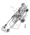
- FIG. 1 an exemplary battery-powered lawn mower 10 (hereinafter, mower) is schematically illustrated.
- the mower 10 includes a battery 12, a cutting mechanism 14 for driving blade(s) 16, a drive mechanism 18 for driving wheels 30, a control circuit 20 and a user interface 22.
- the battery 12 supplies power to the cutting mechanism 14 and the drive mechanism 18, which in the exemplary embodiment shown is a blade motor 54 and a drive motor 56, respectively.
- the amount of power delivered to the drive mechanism 18 by the battery 12 is determined by the control circuit 20 which is managed by the user interface 22.
- the exemplary battery-powered lawn mower 10 includes a deck 50 that provides a mounting structure for various components of the mower 10, including the blade motor 54 and the drive motor 56, and generally forms the housing for the blade(s) 16 coupled to the blade motor 54.
- a shroud 13 is placed over the deck 50 to protect the internal components of the mower 10.
- the shroud 13 defines a pocket 51 that receives the battery 12.
- the battery 12 has a shape that corresponds to the shape of the pocket 51 such that the battery 12 fits snugly within the pocket 51.
- the pocket 51 includes a base portion 719 with a plurality of walls 715 arranged substantially perpendicular to the base portion 719.
- the shape of the battery 12 complements the shape of the pocket 51 such that the battery 12 can be inserted within the pocket in a single orientation.
- Pocket 51 can define one or more recesses 712A-D ( FIG. 7 ) that correspond to one or more projections 752A-D ( FIGS. 9-10 ) on the battery 12 and one or more projections 714A-C that correspond to one or more recesses 754A-C defined by the battery 12.
- the battery 12 can be inserted within the pocket 51 only when the projection(s) 752A-D, 714A-C and recess(es) 754A-C, 712A-D are properly aligned. Furthermore, the projection(s) 752A-D, 714A-C and recess(es) 754A-C, 712A-D can assist with guiding the battery 12 to the proper positioning within the pocket 51. Additionally, the walls 715 of pocket 51 can be tapered to assist in guiding the battery 12 to the proper positioning within the pocket 51.
- the location of the battery 12 is such that the mower 10 is well-balanced and stable.
- the battery 12 (and pocket 51) is positioned rearward of the longitudinal center 702 of the deck 50 such that a user may more easily maneuver the mower 10. This position puts more weight towards the rear of the mower, which provides increased traction to the rear drive wheel(s) 30 and also aids in tilting or lifting the front wheels off the ground for better maneuverability.
- the battery 12 and pocket 51 may be positioned in the approximate center of the width of the deck 50 to increase stability and inhibit sideways tipping.
- the blade motor 54 (and the axis of rotation of the blade 16) is arranged along the longitudinal center 702 of the deck 50 ( FIGS. 18 and 19 ).
- the center 706 of the battery 12/pocket 51 can be positioned rearward of the longitudinal center 702 by at least fifty percent of the distance L1 between the longitudinal center 702 and the rear wheel axle axis 708.
- the distance L1 between the longitudinal center 702 and the rear wheel axle axis 708 is at least twice the distance L2 between the center 706 of the battery 12/pocket 51.
- the distance L1 can be 380 millimeters and the distance L2 can be 160 millimeters such that the distance L1 is 2.375 times the distance L2.
- the depth of the pocket 51 can be increased. Increasing the depth of the pocket 51 reduces the overall height of the mower 10 with the battery 12 installed. Further, the battery 12 can comprise a large portion of the overall weight of the mower 10. Thus, increasing the depth of the pocket 51 also lowers the center of gravity of the mower 10.
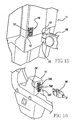
- a latch assembly 720 is coupled to the shroud 13. While latch assembly 720 is an over-center type latch, other latching configurations are may be substituted therefore, such as sliding latches or rotating latches.
- the latch assembly 720 includes a latch 722 and lever 724.
- the latch 722 engages a latch catch 755 formed on the battery 12 to secure the battery 12 within the pocket 51 in a first configuration, as shown in FIG. 3 .
- the lever 724 is rotated, as shown in FIG. 4 , to disengage the latch 724 from the latch catch 755.
- the latch 722 is fully opened and completely disengaged from the battery 12 such that the battery 12 can be freely removed from the pocket 51.
- the battery 12 can be removed from the pocket 51 by moving the battery 12 in the direction of the arrow shown in FIG. 6 .
- the latching assembly 720 may further include a biasing member, e.g., a spring that biases the latching assembly 720 to be in the second configuration.
- a biasing member e.g., a spring that biases the latching assembly 720 to be in the second configuration.
- the biasing member may automatically move the latch 722 to the fully opened position shown in FIG. 5 .
- the latching assembly 720 may be easily moved from the first configuration ( FIG. 3 ) to the second configuration ( FIG. 5 ) by a user utilizing one hand.
- a user manually engages the latch 722 with the latch catch 755 while rotating the lever 724. Then, the lever 724 is moved to the lock position while the latch 722 is engaged with the latch catch 755 ( FIG. 3 ).
- a mower connector 716 is provided within the pocket 51.
- the mower connector 716 can include one or more projections 717 extending from the pocket 51.
- the one or more projections 717 are configured to mate with corresponding recess(es) 757 of a first battery connector 756 in a malefemale connector configuration.
- the projection(s) 717 and recess(es) 757 may act as guide features that assist in positioning the battery 12 within the pocket 51.
- the mower connector 716 and/or the first battery connector 756 can be self-aligning to ensure a proper connection between the mower 10 and battery 12.
- the latching assembly 720 is used to fully secure and couple the mower connector 716 with the first battery connector 756.
- the battery 12 may include a second battery connector 758 ( FIGS. 8 and 15 ), e.g., for connection with a charger cable 780 ( FIG. 15 ).
- the second battery connector 758 ( FIG. 8 ) is located on a portion of the battery 12 that is inaccessible to a user when the battery 12 is in the first configuration, i.e., secured within pocket 51, such that the battery 12 cannot be charged through the second battery connector 758 when the mower 10 is operating.
- the first battery connector 756 is utilized to provide power to the mower 10 and also to charge the battery 12, while the second battery connector 758 is used only to charge the battery 12 (via charger cable 780).
- the charger cable 780 can be constructed to engage with the second battery connector 758 in a single orientation. Any or all of the mower connector 716, first battery connector 756 and second battery connector 758 can be one or more Anderson-type electrical connectors to ensure proper electrical connections.
- the charger cable 780 is connected to an electrical connector portion 732 associated with user interface 22, as is described more fully below.
- User interface 22 is electrically coupled to the mower connector 716 such that power may be provided to the battery 12 when coupled with mower connector 716.
- FIGS. 12 and 16 A portion of an exemplary user interface 22 is shown in FIGS. 12 and 16 .
- User interface 22 includes an electrical connector portion 732 that has three electrical connectors 734A-C.
- Electrical connectors 734A-C can be any type of electrical connector, such as Anderson-type electrical connectors.
- Electrical connectors 734A and 734B are utilized to connect with charger cable 780 to charge the mower 10.
- Electrical connectors 734A and 734C are utilized to connect with a safety key 740 ( FIGS. 13-14 ), further described below.
- the electrical connectors 734A-C can be arranged such that the charger cable 780 can be engaged with electrical connector portion 732 in a single orientation, i.e., connected with electrical connectors 734A and 734B.
- safety key 740 includes two electrical connectors 742A and 742B. Electrical connectors 742A and 742B are configured to mate with electrical connectors 734A and 734C of the user interface 22. For example only, electrical connectors 742A and 742B may be coupled by a jumper 744 to electrically couple electrical connectors 734A and 734C when the safety key 740 is mated with electrical connector portion 732.
- Safety key 740 includes a keyed portion 746 that has a shape that corresponds and complements the shaped of keyed portion 736 of user interface 22.
- the keyed portions 736, 746 and electrical connectors 742A, 742B, 734A and 734C may be constructed and arranged symmetrically such that the safety key 740 can properly mate with electrical connector portion 734 in either of two orientations, i.e., 742A with 734A and 742B with 734C or 742A with 734C and 742B with 734A.
- the safety key 740 operates to connect the battery 12 with the blade and drive motors 54, 56 when mated with the electrical connector portion 732. When the safety key is removed from the electrical connector portion 732, electrical connectors 734A and 734C are decoupled and power from the battery 12 cannot be delivered to either the blade and/or drive motors 54, 56.
- Battery 12 includes three cells 770A-C, which can be connected in series and arranged within a housing 760. However, it should be understood that the battery may include any number of cells and fall within the scope of the present disclosure.
- the housing 760 includes a first portion 762 mated with a second portion 764.
- the first battery connector 756 is arranged on the second portion 764 and the second battery connector 758 is arranged on the first portion 762.
- the battery 12 further includes a first handle 766A and a second handle 766B.
- the first and second handles 766A-B may be utilized by a user to insert or remove the battery 12 from the pocket 51.
- the first and second handles 766A-B are monolithically formed with the first portion 762 of the housing 760.
- the first handle 766A is arranged on a first side 767 of the housing 760 and the second handle 766B is arranged on a second side 769 of the housing 760 that is opposite the first side to encourage a user to use two hands when handling the battery 12.
- the battery 12 is inserted within pocket 51 as follows.
- a user positions the battery 12 within pocket 51.
- the user may grasp first and second handles 766A-B in order to lift and position the battery 12 within pocket 51.
- the battery 12 is properly positioned and fully inserted within pocket 51 such that the first battery connector 756 engages and mates with mower connector 716.
- various features of the battery 12 and/or pocket 51 assist in the proper positioning and insertion of the battery 12 (projections 752A-D, 714A-C, 717, recess(es) 754A-C, 712A-D, 757, etc.).
- the user engages the latch 722 with the battery 12, for example, latch catch 755. The user then rotates the lever 724 to lock the latch 722 and fully secure the battery 12 within the pocket 51.
- the battery 12 is removed from being fully secured within pocket 51 as follows.
- a user rotates lever 724 to unlock the latch 722 from engagement with the battery 12.
- the latch 722 automatically disengages from the battery 12 upon being unlocked.
- the user manually disengages the latch 722 from battery 12.
- a user then grasps the battery (such as, first and second handles 766A-B) in order to remove the battery 12 from pocket 51.
- the mower connector 716 automatically disengages from first battery connector 756 as the battery 12 is removed from pocket 51.
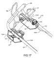
- FIG. 17 Another view of the user interface 22 is shown in FIG. 17 .
- User interface 22 is secured to a handle assembly 100.
- the handle assembly 100 can include handle frames 103 that generally extend at an angle from the mower deck 50 to a handle grip 105.
- the handle assembly 100 can include a first or blade bail 101 and a second or drive bail 102.
- the blade bail 101 can cooperate with a control cable 104A to selectively provide power from battery 12 to blade motor 54 to drive blade 16.
- the drive bail 102 can cooperate with control cable 104B to communicate with the drive motor 56.
- the blade bail 101 can be rotated toward the handle grip 105 about an axis 101A.
- the drive bail 102 can be rotated toward the handle grip 105 about an axis 102A.
- Blade bail 101 is actuated to switch the mower 10 between a cutting OFF mode and a cutting ON mode. In the cutting OFF mode, the blade bail 101 electrically disconnects the battery 12 from the blade motor 54 such that the blade 16 is not driven. In the cutting ON mode, the blade bail 101 electrically connects the battery 12 to the blade motor 54 such that the blade 16 may be driven.
- drive bail 102 is actuated to switch the mower 10 between a self-drive OFF mode and a self-drive ON mode. In the self-drive OFF mode, the drive bail 102 electrically disconnects the battery 12 from the drive motor 56 such that the mower 10 is not propelled. In the self-drive ON mode, the drive bail 102 electrically connects the battery 12 to the drive motor 56 such that the mower 10 is propelled, e.g., by drive wheel(s) 30.
- user interface 22 can further include a safety lock-out mechanism 107, which prevents coupling the battery 12 with the blade motor 54. Therefore, in order to actuate the blade motor 54, a user depresses the lock-out mechanism 107 and pulls the blade bail 101 toward the handle grip 105 (that is, rotates the mower blade bail handle 101 counterclockwise in FIG. 17 ) to start the blade motor 54. In this manner, a user must complete two independent steps to actuate the blade bail 101 and start rotation of blade 16.
- An example lock-out mechanism 107 is disclosed in United States Patent No. 7,762,049 , which is herein incorporated by reference in its entirety.
- the drive speed of mower 10 can be adjusted by moving a speed control lever 108 on the user interface 22.
- the speed control lever 108 is coupled to the control circuit 20 which controls the power delivery from the battery 12 to the drive motor 56. Adjustment of the speed control lever 108 varies the voltage provided to drive motor 56 and thereby varies the speed of the mower 10.
- the drive speed of the mower 10 could be adjusted based on the position of the drive bail 102 such that, as the drive bail 102 is rotated clockwise, it progressively makes the drive mechanism 18 (and the lawn mower 10 as a whole) go faster.
- the voltage may be varied, for example, by changing the duty cycle of a pulse width modulated voltage signal or by adjusting the magnitude of the voltage delivered to the drive mechanism 18.
- the bottom of deck 50 defines a cutting chamber 120 in which blade 16 is arranged.
- Cutting chamber 120 can have a toroidal shape.
- the deck 50 in combination with a discharge plate 121, defines discharge passage 122.
- Discharge passage 122 extends from the cutting chamber 120 to a discharge port 123.
- the discharge passage 122 provides an outlet for grass and/or other waste to exit the cutting chamber 120, e.g., to be discharged or collected by a collection bag 80.
- a mulch door 124 can be coupled to the deck 50 and be arranged between the cutting chamber 120 and discharge passage 122.
- Mulch door 124 can be shaped to complement the toroidal shape of the cutting chamber 120.
- the mulch door 124 is movable between a discharge position ( FIG. 19 ) and a mulch position ( FIG. 18 ). In the discharge position, the mulch door 124 unblocks discharge passageway 122 to open the cutting chamber 120 to the discharge port 123.
- mulch door 124 can be arranged to be tangent to the discharge passage 122 in the discharge configuration (as shown in FIG. 19 in which discharge plate 121 is not shown). In the mulch position, mulch door 124 blocks discharge passageway 122.
- the mulch door 124 can be rotated between the discharge and mulch positions.
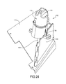
- a mulch door rotation mechanism 130 can be coupled with the mulch door 124 to rotate the mulch door 124 between the discharge and mulch positions.
- the mulch door rotation mechanism 130 can include a knob 131 that is coupled to the mulch door 124 such that the mulch door 124 rotates with the knob 131.
- the knob 131 is coupled to the mulch door 124 by a vertical shaft 133 that extends through a spacer 134.
- the spacer 134 is coupled to the deck 50 and is configured to support the knob 131 in the proper position in relation to deck 50.
- Discharge plate 121 and deck 50 cooperate to define a grass outlet aperture 125 in discharge passage 122 ( FIG. 22 ).
- the grass outlet aperture 125 provides an outlet for grass clippings and other waste to exit discharge passage 122.
- the mulch door 124 will sweep any grass clippings/waste from the discharge passage 122/discharge plate 121 out of the grass outlet aperture 125.
- the mulch door rotation mechanism 130 can further include a locking mechanism 132 that secures the knob 131 and mulch door 124 in specific positions, such as the discharge configuration and the mulch configuration.
- the locking mechanism 132 includes a compression spring 135, a pin 136 and one or more detents defined by the spacer 134, such as first and second detents 137A, 137B.
- the pin 136 is fixedly coupled to and rotatable with knob 131 and is arranged within an aperture 138 defined by spacer 134.
- the pin 136 is movable within aperture 138 and interacts with first and second detents 137A, 137B to provide locking positions for the mulch door 124.
- Compression spring 135 is arranged between spacer 134 and knob 131 and acts to bias the knob 131 to be in the positions defined by detents 137A, 137B.
- a user pushes on knob 131 to compress the compression spring 135 and release the pin 136 from one of the detent positions. The knob 131 can then be freely rotated to another position.
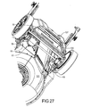
- grass clippings and other waste will travel through the discharge passage 122 and out of the discharge port 123 during operation of mower 10. This waste can either be collected in collection bag 80 or be discharged.
- FIG. 26 shows a discharge door 127 attached to the rear of the mower 10 to deflect grass clippings/waste from the discharge passage 122 downwardly.
- Discharge door 127 can be U-shaped or otherwise constructed such that discharge door 127 defines a discharge cavity 128 to provide the space necessary for the passage of the clippings.
- the discharge door 128 can include an angled portion 127A that directs the flow of grass clippings/waste out of the bottom of the discharge cavity 128.
- collection bag 80 can be coupled to deck 50 as is known in the art, for example, by lifting discharge door 127, as illustrated in FIGS. 21 and 23 .
- Mower 10 includes a blade motor 54 for driving blade 16 and a drive motor 56 for imposing motion onto drive wheel(s) 30 in order to propel the mower 10.
- the blade and drive motors 54, 56 can be operated independently. That is, the blade 16 can be powered by the blade motor 54 without the drive motor 56 propelling the mower 10 and the drive motor 56 can be powered to propel the mower 10 without the blade motor 54 driving the blade 16.
- Drive motor 56 may be coupled to driving wheel(s) 30 through at least one gear mechanism.
- the present exemplary gear mechanism shown in FIG. 20 is a multi-stage gear reduction having a planetary gear assembly 57, a self-drive transmission 58, a drive axle gear 59A. and a wheel gear 31.
- the planetary gear assembly 57 and a self-drive transmission 58 translates a rotational output of the drive motor 56 into a rotational output of a drive axle 59 coupled to drive wheel(s) 30.
- the self-drive transmission 58 is a worm gear that engages the drive motor 56 (through planetary gear assembly 57) to the drive wheel(s) 30 during self-drive operation, while permitting free-wheeling operation when the drive motor 56 is not powered.
- the drive axle 59 is coupled to the drive wheel(s) 30 through a drive axle gear 59A that interacts with a wheel gear 31.
- the gear mechanism provides a gear reduction from the drive motor 56 to the drive wheels 30 to translate the revolutions per minute ("rpm") of the drive motor 56 to the drive speed of the motor (the rpm of the drive wheels 30).
- the drive motor 56 can operate between 6,000 and 17,000 revolutions per minute and the gear mechanism can have a gear reduction between 90:1 and 130:1, for example.
- the planetary gear assembly 57 provides a first gear reduction (a planetary gear reduction) from drive motor 56, while self-drive transmission 58 provides a second gear reduction (a worm gear reduction). Additionally, the gear ratio of the drive axle gear 59A and wheel gear 31 can provide a third reduction.
- the first gear reduction can be 3.67:1
- the second gear reduction can be 9:1
- the third gear reduction can be 3.25:1 to provide a total gear reduction from drive motor 56 to wheel(s) of 107.3:1.
- the maximum drive speed of mower 10 will be approximately 2.5 miles per hour.
- blade motor 54 is coupled to deck 50 with a first end 54A arranged within a chamber 90 defined by deck 50 and a second end 54B coupled to the blade 16 in the cutting chamber 120.
- Blade motor 54 is configured to be cooled by a flow of air entering the first end 54A from the cooling chamber 90 and exiting from the second end 54B into the cutting chamber 120.
- Air can enter chamber 90, e.g., through one or more windows 92 defined by deck 50 to provide a vent to external air, as described more fully below.
- the blade motor 54 is configured to convey air from the chamber 90 to the cutting chamber 120 in order to cool the blade motor 54.
- the second chamber 91 includes one or more windows 92 that allow air in the second chamber 91 to escape into an air passageway connected to the first chamber 90.
- the air passageway is defined by the deck 50 and shroud 13 (not shown in Fig. 28 ) and is located to the side of the battery in Fig. 28 .
- Air in the first chamber 90 is then vented to the external environment through blade motor 54. Additionally, operation of the blade motor 54 will create negative pressure in the first chamber 90 relative to the second chamber 91 and generate an air flow from the second chamber 91 to help cool the drive motor 56.
- control circuit 20 can be configured to protect the mower 10 from an electrical overload condition, such as a short circuit. Upon detection of an overload condition, the control circuit 20 will electrically disconnect the battery 12 from the drive motor 56.
- An overload condition can include the situation in which current provided to the drive motor 56 exceeds a threshold. Alternatively or in addition to current exceeding a threshold, an overload condition can include current exceeding a threshold for a predetermined period. In some embodiments, an overload condition can include current exceeding a second threshold for a second predetermined period, in which the second threshold is greater than the first threshold and the second predetermined period is shorter than the first predetermined period.
- an overload condition can be defined as a condition in which current delivered to the drive motor 56 is greater than 10 amperes but less than 15 amperes for a period of 5 or more seconds, or greater than 15 amperes for a period of 1 or more seconds. While the above description is limited to describing an overload condition for the drive motor 56, it will be appreciated that an overload condition for blade motor 54 is also within the scope of the present disclosure.
- control circuit 20 can be configured to provide a soft-start to drive motor 56 in order to reduce or eliminate abrupt movement (or "jump") of the mower 10 at the beginning of self-drive operation.
- the control circuit 20 upon actuation of the drive bail 102 the control circuit 20 will gradually increase the voltage provided to drive motor 56 until reaching the desired operating voltage, e.g., the operating voltage determined by the position of speed control lever 108.
- control circuit 20 will increase the voltage provided to drive motor 56 over a predetermined period, such as 1-3 seconds.
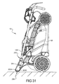
- the handle assembly 100 is capable of being rotated in relation to the deck 50 in order to "fold" the handle assembly 100 over the deck 50 to reduce the size of mower 10 for storage.
- two handle plates 200 fixedly coupled to deck 50 can be utilized to couple the handle assembly 100 with the deck 50.
- Handle frames 103 can be rotatably coupled to handle plates 200 by fasteners 201, such as a nut and bolt.
- a knob assembly 210 that is offset from the fasteners 201 can interact with one or more openings 202A-C defined by handle plates 200 to inhibit rotation of the handle assembly 100. Openings 202A and 202B are utilized to lock the handle assembly 100 in the proper position for operation of mower 10.
- Openings 202A and 202B each correspond to a different position of handle assembly 100, which can be selected based on user preference. Opening 202C corresponds to a storage position in which handle assembly 100 is folded over deck 50.
- the storage position ( FIG. 31 ) of handle assembly 100 permits mower 10 to be stored vertically, e.g., with a contact portion 205 of handle plates 200 in resting on a storage surface.
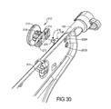
- an exemplary knob assembly 210 includes a graspable knob 212 that is coupled with an extension peg 214 by a pin 216 inserted into an opening 218 defined by graspable knob 212.
- Extension peg 214 can be biased to an extended or locked position, e.g., by a spring, in which knob contact surface 213 contacts handle frame 103 and extension peg 214 is extended, e.g., into openings 202A-C.
- a user pulls on graspable knob 212.
- graspable knob 212 can move the knob assembly 210 to a released position in which extension peg 214 is retracted such that extension peg 214 does not interact with opening(s) 202A-C and the handle assembly can be freely rotated.
- graspable knob 212 can define an aperture 215 that interacts with a projection 106 formed on handle frames 103.
- the shape of aperture 215 can complement the shape of projection 106 to inhibit rotation of the graspable knob 212 in the locked position and to secure the knob assembly in the released position when the graspable knob 212 is rotated.
Abstract
Description
- This application is a continuation-in-part of
U.S. Serial No. 12/838,898, filed July 19, 2010 U.S. Design Application No. 29/361,418, filed on May 11, 2010 U.S. Application Serial No. 12/426,499, filed April 20, 2009 U.S. Provisional Application No. 61/048,002, filed April 25, 2008 - The present disclosure relates to lawn mowers and more specifically to a cordless electric lawn mower.
- Due to concerns regarding urban air pollution, the problems and maintenance needs of gas engines, as well as other factors, electric lawn mowers are gaining in popularity. Moreover, due to the inconveniences and operating limitations of corded electric mowers, battery operated cordless electric mowers may be preferred. As described herein however, such battery operated mowers can have drawbacks.
- Some of these drawbacks can be associated with the functionality of the battery, including battery life and the storage and transfer of the battery, including insertion and removal of the battery from the mower.
- Other drawbacks are associated with self-drive transmissions that use a belttensioning drive system, whereby the tension on a set of variable stepped sheaves can be configured to control the speed of a drive axle from a continuous speed motor. Such a system however is inefficient because the self-drive motor must run constantly at high speed, thereby constantly drawing maximum power. Furthermore, as is known in the art, efficiency losses are observed in such a slipping belt system.
- According to other drawbacks associated with battery operated mowers, in some instances during high-load grass cutting (i.e., wet, and/or thick grass), the operating speed of the blade motor(s) is reduced while the speed of a self-drive motor is unchanged. In this way, cutting performance is degraded because the speed of the self-drive motor is not adjusted to compensate for the reduced operating speed of the blade motor.
- Other drawbacks associated with battery operated mowers involve a cumbersome mulching mode switching process and inadequate driver feedback information. For example, it may be desirable for an operator to easily obtain information relating to battery-power, mower blade operation, self-drive motor operation and/or other information, such as operational faults associated with the mower.
- In one aspect of the invention there is provided a cordless mower comprising:
- a deck supported by front and rear wheels, the deck having a top side, a bottom side, a front end and a rear end, the bottom side defining a cutting chamber;
- a rechargeable battery supported on said deck;
- a blade for cutting grass on the bottom side of the deck;
- a blade motor coupled to the blade; and
- a drive motor connected to the rear wheels for driving said rear wheels, the drive motor located in a chamber at the rear of the mower adjacent the rear wheels, the chamber having an opening therein to allow air to flow through.
- Preferably the blade motor is positioned generally centrally on the deck and an air pathway connects the drive motor with the blade motor through the opening in the chamber.
- Preferably when the blade motor is actuated it creates a negative air pressure zone to draw air through the air pathway from the chamber.
- Preferably the battery is positioned on the top side of the mower behind the blade motor and in front of the drive motor.
- Preferably the top side of the deck is covered by a shroud having a pocket, and the battery is removably secured within said pocket.
- Preferably the cordless mower comprises:
- a speed lever controlled by a user to set the speed of the mower; and
- a control circuit connected to the speed lever that controls the amount of current delivered from the battery to the drive motor, the control circuit monitoring the drive motor and shutting off the drive motor when the current being delivered exceeds a first predetermined current for a first predetermined period of time.
- Preferably the control circuit shuts off the drive motor when the current being delivered exceeds a second predetermined current for a second predetermined time period, wherein the second predetermined current is higher than the first predetermined current, and the second predetermined time period is shorter than the first predetermined time period.
- Preferably the drive motor is connected to the rear wheels through at least one gear mechanism, the drive motor having an rpm of 6,000 to 17,000 rpm and the gear mechanism having a gear reduction between 90:1 and 130:1.
- Preferably the gear mechanism has three separate gear reductions, and at least one is a planetary gear reduction and another a worm gear reduction.
- Preferably the cordless mower comprises a handle secured to said the rear end of said deck, and said handle having a blade bail for controlling power to the blade motor and a drive bail for controlling power to said drive motor so that power to the blade motor and the drive motor are independently controlled.
- Preferably the cordless mower comprises a safety key that is electrically coupled to both the blade motor and drive motor, so that when present, electrical power may be delivered from the battery to both the blade motor and drive motor, and when absent, no power can be delivered to the blade motor and drive motor.
- Preferably the cordless mower comprises a mulch door positioned in a discharge passage defined by the bottom side of the deck and extending rearwardly from the cutting chamber to the rear of said mower, the mulch door being movable between an open and closed position, the mulch door rotating about a vertical shaft that is connected to a user controlled knob located at the top side of the deck.
- Preferably the discharge passage defines a grass outlet aperture at the rear end of the deck and the mulch door is positioned inwardly of the grass outlet aperture and wherein the mulch door swings outwardly when moving from the closed to open position so that any debris in the discharge passage behind the mulch door is swept into the grass outlet aperture and removed from the discharge passage.
- Preferably the cordless mower comprises a rear discharge door spaced from the rear end of the deck to create a discharge cavity to direct debris downward.
- A cordless mower includes a deck, a rechargeable battery, a blade for cutting grass, a blade motor and a drive motor. The deck is supported by front and rear wheels and has a top side, a bottom side, a front end and a rear end. The rechargeable battery is supported on the deck. The blade is on the bottom side of the deck and is coupled with a blade motor. The drive motor is connected to the rear wheels for driving said rear wheels to move the mower and is located in a chamber at the rear of the mower adjacent the rear wheels. The chamber has an opening therein to allow air to flow through.
- A cordless mower includes a deck, a rechargeable battery, a drive motor, a speed lever and a control circuit. The deck is supported by front and rear wheels and has a top side, a bottom side, a front end and a rear end. The rechargeable battery is supported on said deck. The drive motor is connected to the rear wheels for driving said rear wheels to move the mower. The speed lever is controlled by a user to set the speed of the mower. The control circuit is connected to the speed lever and controls the amount of current delivered from the battery to the drive motor. The control circuit monitors the drive motor and shuts off the drive motor when the current being delivered exceeds a predetermined current for a predetermined period of time.
- A cordless mower includes a deck, a rechargeable battery, a drive motor, a blade motor and a handle. The deck is supported by front and rear wheels and has a top side, a bottom side, a front end and a rear end. The rechargeable battery is supported on said deck. The drive motor is connected to the rear wheels for driving said rear wheels to move the mower. The blade motor is coupled to a blade. The handle is secured to the rear end of said deck. The handle has a blade bail for controlling power to the blade motor and a drive bail for controlling power to said drive motor so that power to the blade motor and the drive motor are independently controlled.
- A cordless mower includes a deck, a rechargeable battery, a blade for cutting grass and a mulch door. The deck is supported by front and rear wheels and has a top side, a bottom side, a front end and a rear end. The bottom side defines a cutting chamber and a discharge passage extending rearwardly from the cutting chamber to the rear of said mower. The rechargeable battery is supported on said deck. The blade is arranged within the cutting chamber. The mulch door is positioned in said discharge passage and is movable between an open and closed position. The mulch door rotates about a vertical shaft that is connected to a knob located at a top side of the deck.
- Further areas of applicability will become apparent from the description provided herein. It should be understood that the description and specific examples are intended for purposes of illustration only and are not intended to limit the scope of the present disclosure.
- The drawings described herein are for illustration purposes only and are not intended to limit the scope of the present disclosure in any way.
-
FIG. 1 is a schematic block diagram of an exemplary battery-powered mower constructed in accordance with the teachings of the present disclosure; -
FIG. 2 is a perspective view of an exemplary battery-powered lawn mower constructed in accordance with the teachings of the present disclosure; -
FIG. 3 is a partial perspective view of the exemplary battery-powered lawn mower shown inFIG. 2 in a first configuration; -
FIG. 4 is a partial perspective view of the exemplary battery-powered lawn mower shown inFIG. 2 ; -
FIG. 5 is a partial perspective view of the exemplary battery-powered lawn mower shown inFIG. 2 in a second configuration; -
FIG. 6 is a perspective view of the exemplary battery-powered lawn mower shown inFIG. 2 with the battery being removed from the pocket; -
FIG. 7 is a partial plan view of the exemplary battery-powered lawn mower shown inFIG. 2 with the battery removed to illustrate the pocket; -
FIG. 8 is a perspective view of the battery of the exemplary battery-powered lawn mower shown inFIG. 2 ; -
FIG. 9 is another perspective view of the battery of the exemplary battery-powered lawn mower shown inFIG. 2 ; -
FIG. 10 is a bottom view of the battery of the exemplary battery-powered lawn mower shown inFIG. 2 ; -
FIG. 11 is a partial perspective view of the battery of the exemplary battery-powered lawn mower shown inFIG. 2 with a portion of the battery housing removed to illustrate a series of cells housed therein; -
FIG. 12 is a partial perspective view of a control of the exemplary battery-powered lawn mower shown inFIG. 2 ; -
FIG. 13 is a perspective view of a safety key corresponding to the exemplary battery-powered lawn mower shown inFIG. 2 ; -
FIG. 14 is a partial sectional view of the safety key ofFIG. 13 ; -
FIG. 15 is a partial perspective view of the battery of the exemplary battery-powered lawn mower shown inFIG. 2 with an exemplary charger cable; -
FIG. 16 is a partial perspective view of the exemplary control assembly shown inFIG. 12 with an exemplary charger cable; -
FIG. 17 is another partial perspective view of a control assembly of the exemplary battery-powered lawn mower shown inFIG. 2 ; -
FIG. 18 is a partial plan view of the exemplary battery-powered lawn mower shown inFIG. 2 in a mulch configuration ; -
FIG. 19 is a partial plan views of the exemplary battery-powered lawn mower shown inFIG. 2 in a discharge configuration; -
FIG. 20 is a partial perspective view of a drive mechanism of the exemplary battery-powered lawn mower shown inFIG. 2 ; -
FIG. 21 is a partial perspective rear view of the exemplary battery-powered lawn mower shown inFIG. 2 showing a mulch door; -
FIG. 22 is another partial perspective rear view of the exemplary battery-powered lawn mower shown inFIG. 2 showing a mulch door; -
FIG. 23 is another partial perspective view of the exemplary battery-powered lawn mower shown inFIG. 2 ; -
FIG. 24 is a partial perspective view of a mulch door rotation mechanism of the exemplary battery-powered lawn mower shown inFIG. 2 ; -
FIG. 25 is a partial perspective view of a mulch door rotation mechanism of the exemplary battery-powered lawn mower shown inFIG. 2 ; -
FIG. 26 is another partial perspective rear view of the exemplary battery-powered lawn mower shown inFIG. 2 ; -
FIG. 27 is another partial perspective rear view of the exemplary battery-powered lawn mower shown inFIG. 2 ; -
FIG. 28 is a partial perspective view of the exemplary battery-powered lawn mower shown inFIG. 2 with a portion of the deck removed; -
FIG. 29 is a partial sectional view taken through the deck of the exemplary battery-powered lawn mower shown inFIG. 2 ; -
FIG. 30 is a partial perspective view of a knob assembly of the exemplary battery-powered lawn mower shown inFIG. 2 ; and -
FIG. 31 is a side view of the exemplary battery-powered lawn mower shown inFIG. 2 in a storage configuration. - With initial reference to
FIG. 1 , an exemplary battery-powered lawn mower 10 (hereinafter, mower) is schematically illustrated. Themower 10 includes abattery 12, acutting mechanism 14 for driving blade(s) 16, adrive mechanism 18 for drivingwheels 30, acontrol circuit 20 and auser interface 22. Thebattery 12 supplies power to thecutting mechanism 14 and thedrive mechanism 18, which in the exemplary embodiment shown is ablade motor 54 and adrive motor 56, respectively. The amount of power delivered to thedrive mechanism 18 by thebattery 12 is determined by thecontrol circuit 20 which is managed by theuser interface 22. - With reference to
FIGS. 2 and28 , the exemplary battery-poweredlawn mower 10 will be described. Themower 10 includes adeck 50 that provides a mounting structure for various components of themower 10, including theblade motor 54 and thedrive motor 56, and generally forms the housing for the blade(s) 16 coupled to theblade motor 54. Ashroud 13 is placed over thedeck 50 to protect the internal components of themower 10. - With reference to
FIGS. 6 and7 , theshroud 13 defines apocket 51 that receives thebattery 12. Thebattery 12 has a shape that corresponds to the shape of thepocket 51 such that thebattery 12 fits snugly within thepocket 51. - With additional reference to
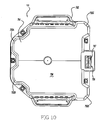
FIG. 7 , thepocket 51 includes abase portion 719 with a plurality ofwalls 715 arranged substantially perpendicular to thebase portion 719. The shape of thebattery 12 complements the shape of thepocket 51 such that thebattery 12 can be inserted within the pocket in a single orientation.Pocket 51 can define one ormore recesses 712A-D (FIG. 7 ) that correspond to one ormore projections 752A-D (FIGS. 9-10 ) on thebattery 12 and one ormore projections 714A-C that correspond to one ormore recesses 754A-C defined by thebattery 12. In this manner, thebattery 12 can be inserted within thepocket 51 only when the projection(s) 752A-D, 714A-C and recess(es) 754A-C, 712A-D are properly aligned. Furthermore, the projection(s) 752A-D, 714A-C and recess(es) 754A-C, 712A-D can assist with guiding thebattery 12 to the proper positioning within thepocket 51. Additionally, thewalls 715 ofpocket 51 can be tapered to assist in guiding thebattery 12 to the proper positioning within thepocket 51. - The location of the
battery 12 is such that themower 10 is well-balanced and stable. The battery 12 (and pocket 51) is positioned rearward of thelongitudinal center 702 of thedeck 50 such that a user may more easily maneuver themower 10. This position puts more weight towards the rear of the mower, which provides increased traction to the rear drive wheel(s) 30 and also aids in tilting or lifting the front wheels off the ground for better maneuverability. In addition, thebattery 12 andpocket 51 may be positioned in the approximate center of the width of thedeck 50 to increase stability and inhibit sideways tipping. - The blade motor 54 (and the axis of rotation of the blade 16) is arranged along the
longitudinal center 702 of the deck 50 (FIGS. 18 and19 ). Thecenter 706 of thebattery 12/pocket 51 can be positioned rearward of thelongitudinal center 702 by at least fifty percent of the distance L1 between thelongitudinal center 702 and the rearwheel axle axis 708. In other words, the distance L1 between thelongitudinal center 702 and the rearwheel axle axis 708 is at least twice the distance L2 between thecenter 706 of thebattery 12/pocket 51. For example only, the distance L1 can be 380 millimeters and the distance L2 can be 160 millimeters such that the distance L1 is 2.375 times the distance L2. - In order to further increase stability and inhibit tipping of the
mower 10, the depth of thepocket 51 can be increased. Increasing the depth of thepocket 51 reduces the overall height of themower 10 with thebattery 12 installed. Further, thebattery 12 can comprise a large portion of the overall weight of themower 10. Thus, increasing the depth of thepocket 51 also lowers the center of gravity of themower 10. - With reference to
FIGS. 3-6 , alatch assembly 720 is coupled to theshroud 13. Whilelatch assembly 720 is an over-center type latch, other latching configurations are may be substituted therefore, such as sliding latches or rotating latches. Thelatch assembly 720 includes alatch 722 andlever 724. Thelatch 722 engages alatch catch 755 formed on thebattery 12 to secure thebattery 12 within thepocket 51 in a first configuration, as shown inFIG. 3 . Thelever 724 is rotated, as shown inFIG. 4 , to disengage thelatch 724 from thelatch catch 755. In a second configuration shown inFIG. 5 , thelatch 722 is fully opened and completely disengaged from thebattery 12 such that thebattery 12 can be freely removed from thepocket 51. As more fully described below, thebattery 12 can be removed from thepocket 51 by moving thebattery 12 in the direction of the arrow shown inFIG. 6 . - The latching
assembly 720 may further include a biasing member, e.g., a spring that biases the latchingassembly 720 to be in the second configuration. Upon releasing thelatch 722 from engagement with thelatch catch 755, the biasing member may automatically move thelatch 722 to the fully opened position shown inFIG. 5 . In this manner, the latchingassembly 720 may be easily moved from the first configuration (FIG. 3 ) to the second configuration (FIG. 5 ) by a user utilizing one hand. In order to secure thebattery 12 within thepocket 51, a user manually engages thelatch 722 with thelatch catch 755 while rotating thelever 724. Then, thelever 724 is moved to the lock position while thelatch 722 is engaged with the latch catch 755 (FIG. 3 ). - With reference to
FIGS. 2 ,7 and10 , in order to electrically couple thebattery 12 with the other components of themower 10, amower connector 716 is provided within thepocket 51. Themower connector 716 can include one ormore projections 717 extending from thepocket 51. The one ormore projections 717 are configured to mate with corresponding recess(es) 757 of afirst battery connector 756 in a malefemale connector configuration. The projection(s) 717 and recess(es) 757 may act as guide features that assist in positioning thebattery 12 within thepocket 51. Themower connector 716 and/or thefirst battery connector 756 can be self-aligning to ensure a proper connection between themower 10 andbattery 12. In some embodiments, the latchingassembly 720 is used to fully secure and couple themower connector 716 with thefirst battery connector 756. - The
battery 12 may include a second battery connector 758 (FIGS. 8 and15 ), e.g., for connection with a charger cable 780 (FIG. 15 ). The second battery connector 758 (FIG. 8 ) is located on a portion of thebattery 12 that is inaccessible to a user when thebattery 12 is in the first configuration, i.e., secured withinpocket 51, such that thebattery 12 cannot be charged through thesecond battery connector 758 when themower 10 is operating. In this way, thefirst battery connector 756 is utilized to provide power to themower 10 and also to charge thebattery 12, while thesecond battery connector 758 is used only to charge the battery 12 (via charger cable 780). With reference toFIG. 15 , thecharger cable 780 can be constructed to engage with thesecond battery connector 758 in a single orientation. Any or all of themower connector 716,first battery connector 756 andsecond battery connector 758 can be one or more Anderson-type electrical connectors to ensure proper electrical connections. - While the
battery 12 is secured withinpocket 51, thecharger cable 780 is connected to anelectrical connector portion 732 associated withuser interface 22, as is described more fully below.User interface 22 is electrically coupled to themower connector 716 such that power may be provided to thebattery 12 when coupled withmower connector 716. - A portion of an
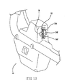
exemplary user interface 22 is shown inFIGS. 12 and16 .User interface 22 includes anelectrical connector portion 732 that has threeelectrical connectors 734A-C. Electrical connectors 734A-C can be any type of electrical connector, such as Anderson-type electrical connectors.Electrical connectors charger cable 780 to charge themower 10.Electrical connectors FIGS. 13-14 ), further described below. In order to inhibit improper connections, theelectrical connectors 734A-C can be arranged such that thecharger cable 780 can be engaged withelectrical connector portion 732 in a single orientation, i.e., connected withelectrical connectors - In
FIGS. 13 and 14 ,safety key 740 includes twoelectrical connectors Electrical connectors electrical connectors user interface 22. For example only,electrical connectors jumper 744 to electrically coupleelectrical connectors safety key 740 is mated withelectrical connector portion 732.Safety key 740 includes a keyedportion 746 that has a shape that corresponds and complements the shaped of keyedportion 736 ofuser interface 22. Thekeyed portions electrical connectors safety key 740 can properly mate with electrical connector portion 734 in either of two orientations, i.e., 742A with 734A and 742B with 734C or 742A with 734C and 742B with 734A. Thesafety key 740 operates to connect thebattery 12 with the blade and drivemotors electrical connector portion 732. When the safety key is removed from theelectrical connector portion 732,electrical connectors battery 12 cannot be delivered to either the blade and/or drivemotors - An
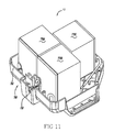
exemplary battery 12 will be described with particular reference toFIGS. 8-11 .Battery 12 includes threecells 770A-C, which can be connected in series and arranged within ahousing 760. However, it should be understood that the battery may include any number of cells and fall within the scope of the present disclosure. Thehousing 760 includes afirst portion 762 mated with asecond portion 764. Thefirst battery connector 756 is arranged on thesecond portion 764 and thesecond battery connector 758 is arranged on thefirst portion 762. - The
battery 12 further includes afirst handle 766A and asecond handle 766B. The first andsecond handles 766A-B may be utilized by a user to insert or remove thebattery 12 from thepocket 51. In a non-limiting example, the first andsecond handles 766A-B are monolithically formed with thefirst portion 762 of thehousing 760. Thefirst handle 766A is arranged on afirst side 767 of thehousing 760 and thesecond handle 766B is arranged on asecond side 769 of thehousing 760 that is opposite the first side to encourage a user to use two hands when handling thebattery 12. - With reference to
FIGS. 7 ,8 and10 , thebattery 12 is inserted withinpocket 51 as follows. A user positions thebattery 12 withinpocket 51. For example only, the user may grasp first andsecond handles 766A-B in order to lift and position thebattery 12 withinpocket 51. Thebattery 12 is properly positioned and fully inserted withinpocket 51 such that thefirst battery connector 756 engages and mates withmower connector 716. As described above, various features of thebattery 12 and/orpocket 51 assist in the proper positioning and insertion of the battery 12 (projections 752A-D, 714A-C, 717, recess(es) 754A-C, 712A-D, 757, etc.). - Once the
battery 12 is fully inserted withinpocket 51 and thefirst battery connector 756 is engaged and mated withmower connector 716, the user engages thelatch 722 with thebattery 12, for example,latch catch 755. The user then rotates thelever 724 to lock thelatch 722 and fully secure thebattery 12 within thepocket 51. - The
battery 12 is removed from being fully secured withinpocket 51 as follows. A user rotateslever 724 to unlock thelatch 722 from engagement with thebattery 12. In some embodiments, thelatch 722 automatically disengages from thebattery 12 upon being unlocked. Alternatively, the user manually disengages thelatch 722 frombattery 12. A user then grasps the battery (such as, first andsecond handles 766A-B) in order to remove thebattery 12 frompocket 51. In various embodiments, themower connector 716 automatically disengages fromfirst battery connector 756 as thebattery 12 is removed frompocket 51. - Another view of the
user interface 22 is shown inFIG. 17 .User interface 22 is secured to ahandle assembly 100. Thehandle assembly 100 can include handleframes 103 that generally extend at an angle from themower deck 50 to ahandle grip 105. Thehandle assembly 100 can include a first orblade bail 101 and a second or drivebail 102. Theblade bail 101 can cooperate with acontrol cable 104A to selectively provide power frombattery 12 toblade motor 54 to driveblade 16. Thedrive bail 102 can cooperate withcontrol cable 104B to communicate with thedrive motor 56. In one example, theblade bail 101 can be rotated toward thehandle grip 105 about anaxis 101A. Thedrive bail 102 can be rotated toward thehandle grip 105 about anaxis 102A. -
Blade bail 101 is actuated to switch themower 10 between a cutting OFF mode and a cutting ON mode. In the cutting OFF mode, theblade bail 101 electrically disconnects thebattery 12 from theblade motor 54 such that theblade 16 is not driven. In the cutting ON mode, theblade bail 101 electrically connects thebattery 12 to theblade motor 54 such that theblade 16 may be driven. Similarly, drivebail 102 is actuated to switch themower 10 between a self-drive OFF mode and a self-drive ON mode. In the self-drive OFF mode, thedrive bail 102 electrically disconnects thebattery 12 from thedrive motor 56 such that themower 10 is not propelled. In the self-drive ON mode, thedrive bail 102 electrically connects thebattery 12 to thedrive motor 56 such that themower 10 is propelled, e.g., by drive wheel(s) 30. - In order to inhibit unintended starting of the
blade 16,user interface 22 can further include a safety lock-outmechanism 107, which prevents coupling thebattery 12 with theblade motor 54. Therefore, in order to actuate theblade motor 54, a user depresses the lock-outmechanism 107 and pulls theblade bail 101 toward the handle grip 105 (that is, rotates the mowerblade bail handle 101 counterclockwise inFIG. 17 ) to start theblade motor 54. In this manner, a user must complete two independent steps to actuate theblade bail 101 and start rotation ofblade 16. An example lock-outmechanism 107 is disclosed in United States Patent No.7,762,049 , which is herein incorporated by reference in its entirety. - To start the drive mechanism 18 a user urges the
drive bail 102 toward the handle grip 105 (that is, rotates thedrive bail 102 clockwise inFIG. 17 ). The drive speed ofmower 10 can be adjusted by moving aspeed control lever 108 on theuser interface 22. Thespeed control lever 108 is coupled to thecontrol circuit 20 which controls the power delivery from thebattery 12 to thedrive motor 56. Adjustment of thespeed control lever 108 varies the voltage provided to drivemotor 56 and thereby varies the speed of themower 10. Alternatively, the drive speed of themower 10 could be adjusted based on the position of thedrive bail 102 such that, as thedrive bail 102 is rotated clockwise, it progressively makes the drive mechanism 18 (and thelawn mower 10 as a whole) go faster. The voltage may be varied, for example, by changing the duty cycle of a pulse width modulated voltage signal or by adjusting the magnitude of the voltage delivered to thedrive mechanism 18. - With reference to
FIGS. 18-25 , the bottom ofdeck 50 defines a cuttingchamber 120 in whichblade 16 is arranged. Cuttingchamber 120 can have a toroidal shape. Thedeck 50, in combination with adischarge plate 121, definesdischarge passage 122.Discharge passage 122 extends from the cuttingchamber 120 to adischarge port 123. During operation ofmower 10, thedischarge passage 122 provides an outlet for grass and/or other waste to exit the cuttingchamber 120, e.g., to be discharged or collected by acollection bag 80. Amulch door 124 can be coupled to thedeck 50 and be arranged between the cuttingchamber 120 anddischarge passage 122.Mulch door 124 can be shaped to complement the toroidal shape of the cuttingchamber 120. Themulch door 124 is movable between a discharge position (FIG. 19 ) and a mulch position (FIG. 18 ). In the discharge position, themulch door 124 unblocksdischarge passageway 122 to open the cuttingchamber 120 to thedischarge port 123. For example,mulch door 124 can be arranged to be tangent to thedischarge passage 122 in the discharge configuration (as shown inFIG. 19 in which dischargeplate 121 is not shown). In the mulch position,mulch door 124 blocks dischargepassageway 122. - The
mulch door 124 can be rotated between the discharge and mulch positions. Referring toFIGS. 23-25 , a mulchdoor rotation mechanism 130 can be coupled with themulch door 124 to rotate themulch door 124 between the discharge and mulch positions. The mulchdoor rotation mechanism 130 can include aknob 131 that is coupled to themulch door 124 such that themulch door 124 rotates with theknob 131. As shown in the example illustrated inFIGS. 24-25 , theknob 131 is coupled to themulch door 124 by avertical shaft 133 that extends through aspacer 134. Thespacer 134 is coupled to thedeck 50 and is configured to support theknob 131 in the proper position in relation todeck 50. -
Discharge plate 121 anddeck 50 cooperate to define agrass outlet aperture 125 in discharge passage 122 (FIG. 22 ). Thegrass outlet aperture 125 provides an outlet for grass clippings and other waste to exitdischarge passage 122. For example, during rotation ofmulch door 124 from the mulch position (FIG. 20 ) to the discharge position (FIG. 19 ) themulch door 124 will sweep any grass clippings/waste from thedischarge passage 122/discharge plate 121 out of thegrass outlet aperture 125. - The mulch
door rotation mechanism 130 can further include alocking mechanism 132 that secures theknob 131 andmulch door 124 in specific positions, such as the discharge configuration and the mulch configuration. In the illustrated example, thelocking mechanism 132 includes acompression spring 135, apin 136 and one or more detents defined by thespacer 134, such as first andsecond detents pin 136 is fixedly coupled to and rotatable withknob 131 and is arranged within anaperture 138 defined byspacer 134. Thepin 136 is movable withinaperture 138 and interacts with first andsecond detents mulch door 124.Compression spring 135 is arranged betweenspacer 134 andknob 131 and acts to bias theknob 131 to be in the positions defined bydetents mulch door 124, a user pushes onknob 131 to compress thecompression spring 135 and release thepin 136 from one of the detent positions. Theknob 131 can then be freely rotated to another position. - As described above, with the
mulch door 124 in the discharge position grass clippings and other waste will travel through thedischarge passage 122 and out of thedischarge port 123 during operation ofmower 10. This waste can either be collected incollection bag 80 or be discharged. - In order to permit rear discharge of grass clippings/waste while preventing the clippings from striking a user of
mower 10, adischarge door 127 can be coupled todeck 50.FIG. 26 shows adischarge door 127 attached to the rear of themower 10 to deflect grass clippings/waste from thedischarge passage 122 downwardly.Discharge door 127 can be U-shaped or otherwise constructed such thatdischarge door 127 defines adischarge cavity 128 to provide the space necessary for the passage of the clippings. Thedischarge door 128 can include anangled portion 127A that directs the flow of grass clippings/waste out of the bottom of thedischarge cavity 128. In order to collect grass clippings/waste,collection bag 80 can be coupled todeck 50 as is known in the art, for example, by liftingdischarge door 127, as illustrated inFIGS. 21 and23 . -
Mower 10 includes ablade motor 54 for drivingblade 16 and adrive motor 56 for imposing motion onto drive wheel(s) 30 in order to propel themower 10. The blade and drivemotors blade 16 can be powered by theblade motor 54 without thedrive motor 56 propelling themower 10 and thedrive motor 56 can be powered to propel themower 10 without theblade motor 54 driving theblade 16. - Drive
motor 56 may be coupled to driving wheel(s) 30 through at least one gear mechanism. However, the present exemplary gear mechanism shown inFIG. 20 is a multi-stage gear reduction having aplanetary gear assembly 57, a self-drive transmission 58, a drive axle gear 59A. and awheel gear 31. Theplanetary gear assembly 57 and a self-drive transmission 58 translates a rotational output of thedrive motor 56 into a rotational output of adrive axle 59 coupled to drive wheel(s) 30. The self-drive transmission 58 is a worm gear that engages the drive motor 56 (through planetary gear assembly 57) to the drive wheel(s) 30 during self-drive operation, while permitting free-wheeling operation when thedrive motor 56 is not powered. Thedrive axle 59 is coupled to the drive wheel(s) 30 through adrive axle gear 59A that interacts with awheel gear 31. - The gear mechanism provides a gear reduction from the
drive motor 56 to thedrive wheels 30 to translate the revolutions per minute ("rpm") of thedrive motor 56 to the drive speed of the motor (the rpm of the drive wheels 30). Thedrive motor 56 can operate between 6,000 and 17,000 revolutions per minute and the gear mechanism can have a gear reduction between 90:1 and 130:1, for example. Theplanetary gear assembly 57 provides a first gear reduction (a planetary gear reduction) fromdrive motor 56, while self-drive transmission 58 provides a second gear reduction (a worm gear reduction). Additionally, the gear ratio of thedrive axle gear 59A andwheel gear 31 can provide a third reduction. For example only, the first gear reduction can be 3.67:1, the second gear reduction can be 9:1 and the third gear reduction can be 3.25:1 to provide a total gear reduction fromdrive motor 56 to wheel(s) of 107.3:1. In this example, if thedrive motor 56 operates at 10,000 revolutions per minute and the drive wheel(s) 30 diameter is 9 inches, the maximum drive speed ofmower 10 will be approximately 2.5 miles per hour. - During operation of
mower 10, the blade and drivemotors FIGS. 28 and29 ,blade motor 54 is coupled todeck 50 with afirst end 54A arranged within achamber 90 defined bydeck 50 and asecond end 54B coupled to theblade 16 in the cuttingchamber 120.Blade motor 54 is configured to be cooled by a flow of air entering thefirst end 54A from the coolingchamber 90 and exiting from thesecond end 54B into the cuttingchamber 120. Air can enterchamber 90, e.g., through one ormore windows 92 defined bydeck 50 to provide a vent to external air, as described more fully below. In this manner, theblade motor 54 is configured to convey air from thechamber 90 to the cuttingchamber 120 in order to cool theblade motor 54. - Drive
motor 56 is arranged adjacent the rear wheels in asecond chamber 91 defined by thedeck 50. Due to its location behind the battery, the limited space of thissecond chamber 91 makes cooling thedrive motor 56 difficult. Therefore, thesecond chamber 91 includes one ormore windows 92 that allow air in thesecond chamber 91 to escape into an air passageway connected to thefirst chamber 90. The air passageway is defined by thedeck 50 and shroud 13 (not shown inFig. 28 ) and is located to the side of the battery inFig. 28 . - Air in the
first chamber 90 is then vented to the external environment throughblade motor 54. Additionally, operation of theblade motor 54 will create negative pressure in thefirst chamber 90 relative to thesecond chamber 91 and generate an air flow from thesecond chamber 91 to help cool thedrive motor 56. - In some embodiments,
control circuit 20 can be configured to protect themower 10 from an electrical overload condition, such as a short circuit. Upon detection of an overload condition, thecontrol circuit 20 will electrically disconnect thebattery 12 from thedrive motor 56. An overload condition can include the situation in which current provided to thedrive motor 56 exceeds a threshold. Alternatively or in addition to current exceeding a threshold, an overload condition can include current exceeding a threshold for a predetermined period. In some embodiments, an overload condition can include current exceeding a second threshold for a second predetermined period, in which the second threshold is greater than the first threshold and the second predetermined period is shorter than the first predetermined period. For example only, an overload condition can be defined as a condition in which current delivered to thedrive motor 56 is greater than 10 amperes but less than 15 amperes for a period of 5 or more seconds, or greater than 15 amperes for a period of 1 or more seconds. While the above description is limited to describing an overload condition for thedrive motor 56, it will be appreciated that an overload condition forblade motor 54 is also within the scope of the present disclosure. - In addition to overload protection,
control circuit 20 can be configured to provide a soft-start to drivemotor 56 in order to reduce or eliminate abrupt movement (or "jump") of themower 10 at the beginning of self-drive operation. In some embodiments, upon actuation of thedrive bail 102 thecontrol circuit 20 will gradually increase the voltage provided to drivemotor 56 until reaching the desired operating voltage, e.g., the operating voltage determined by the position ofspeed control lever 108. For example only,control circuit 20 will increase the voltage provided to drivemotor 56 over a predetermined period, such as 1-3 seconds. - In some embodiments, the
handle assembly 100 is capable of being rotated in relation to thedeck 50 in order to "fold" thehandle assembly 100 over thedeck 50 to reduce the size ofmower 10 for storage. For example and with reference toFIGS. 23 ,30 and31 , two handleplates 200 fixedly coupled todeck 50 can be utilized to couple thehandle assembly 100 with thedeck 50. Handle frames 103 can be rotatably coupled to handleplates 200 byfasteners 201, such as a nut and bolt. Aknob assembly 210 that is offset from thefasteners 201 can interact with one ormore openings 202A-C defined byhandle plates 200 to inhibit rotation of thehandle assembly 100.Openings handle assembly 100 in the proper position for operation ofmower 10.Openings handle assembly 100, which can be selected based on user preference.Opening 202C corresponds to a storage position in which handleassembly 100 is folded overdeck 50. The storage position (FIG. 31 ) ofhandle assembly 100permits mower 10 to be stored vertically, e.g., with acontact portion 205 ofhandle plates 200 in resting on a storage surface. - With specific reference to
FIG. 30 , anexemplary knob assembly 210 includes agraspable knob 212 that is coupled with anextension peg 214 by apin 216 inserted into anopening 218 defined bygraspable knob 212.Extension peg 214 can be biased to an extended or locked position, e.g., by a spring, in whichknob contact surface 213 contacts handleframe 103 andextension peg 214 is extended, e.g., intoopenings 202A-C. In order to release extension peg 214 from opening 202A, 202B or 202C, a user pulls ongraspable knob 212. Furthermore, rotation ofgraspable knob 212 can move theknob assembly 210 to a released position in which extension peg 214 is retracted such thatextension peg 214 does not interact with opening(s) 202A-C and the handle assembly can be freely rotated. For example only,graspable knob 212 can define anaperture 215 that interacts with aprojection 106 formed on handle frames 103. The shape ofaperture 215 can complement the shape ofprojection 106 to inhibit rotation of thegraspable knob 212 in the locked position and to secure the knob assembly in the released position when thegraspable knob 212 is rotated. - While the disclosure has been described in the specification and illustrated in the drawings with reference to various embodiments, it will be understood by those skilled in the art that various changes may be made and equivalents may be substituted for elements thereof without departing from the scope of the disclosure as defined in the claims. Furthermore, the mixing and matching of features, elements and/or functions between various embodiments is expressly contemplated herein so that one of ordinary skill in the art would appreciate from this disclosure that features, elements and/or functions of one embodiment may be incorporated into another embodiment as appropriate, unless described otherwise above. Moreover, many modifications may be made to adapt a particular situation or material to the teachings of the disclosure without departing from the essential scope thereof. Therefore, it is intended that the disclosure not be limited to the particular embodiments illustrated by the drawings and described in the specification as the best mode presently contemplated for carrying out this disclosure, but that the disclosure will include any embodiments falling within the foregoing description and the appended claims.
Claims (14)
- A cordless mower (10) comprising:a deck (50) supported by front and rear wheels (30), the deck (50) having a top side, a bottom side, a front end and a rear end, the bottom side defining a cutting chamber (120);a rechargeable battery (12) supported on said deck (50);a blade (16) for cutting grass on the bottom side of the deck (50);a blade motor (54) coupled to the blade (16); anda drive motor (56) connected to the rear wheels (30) for driving said rear wheels (30), the drive motor (56) located in a chamber (91) at the rear of the mower (10) adjacent the rear wheels (30), the chamber (91) having an opening (92) therein to allow air to flow through.
- The cordless mower (10) of claim 1, wherein the blade motor (54) is positioned generally centrally on the deck (50) and an air pathway connects the drive motor (56) with the blade motor (54) through the opening (92) in the chamber (91).
- The cordless mower (10) of claim 2, wherein when the blade motor (54) is actuated it creates a negative air pressure zone to draw air through the air pathway from the chamber (91).
- The cordless mower (10) of any of claims 1-3, wherein the battery (12) is positioned on the top side of the mower (10) behind the blade motor (54) and in front of the drive motor (56).
- The cordless mower (10) of any of claims 1-4, wherein the top side of the deck (50) is covered by a shroud (13) having a pocket (51), and the battery (12) is removably secured within said pocket (51).
- The cordless mower (10) of any of claims 1-5, further comprising:a speed lever (108) controlled by a user to set the speed of the mower (10); anda control circuit (20) connected to the speed lever (108) that controls the amount of current delivered from the battery (12) to the drive motor (56), the control circuit (20) monitoring the drive motor (56) and shutting off the drive motor (56) when the current being delivered exceeds a first predetermined current for a first predetermined period of time.
- The cordless mower (10) of claim 6, wherein the control circuit (20) shuts off the drive motor (56) when the current being delivered exceeds a second predetermined current for a second predetermined time period, wherein the second predetermined current is higher than the first predetermined current, and the second predetermined time period is shorter than the first predetermined time period.
- The cordless mower (10) of any of claims 6-7, wherein the drive motor (56) is connected to the rear wheels (30) through at least one gear mechanism (57, 58, 59A, 31), the drive motor (56) having an rpm of 6,000 to 17,000 rpm and the gear mechanism (57, 58, 59A, 31) having a gear reduction between 90:1 and 130:1.
- The cordless mower (10) of claim 8, wherein the gear mechanism (57, 58, 59A, 31) has three separate gear reductions, and at least one is a planetary gear reduction (57) and another a worm gear reduction (58).
- The cordless mower (10) of any of claims 1-9, further comprising a handle (100) secured to said the rear end of said deck (50), and said handle (100) having a blade bail (101) for controlling power to the blade motor (54) and a drive bail (102) for controlling power to said drive motor (56) so that power to the blade motor (54) and the drive motor (56) are independently controlled.
- The cordless mower (10) of any of claims 1-10, further comprising a safety key (740) that is electrically coupled to both the blade motor (54) and drive motor (56), so that when present, electrical power may be delivered from the battery (12) to both the blade motor (54) and drive motor (56), and when absent, no power can be delivered to the blade motor (54) and drive motor (56).
- The cordless mower (10) of any of claims 1-11, further comprising a mulch door (124) positioned in a discharge passage (122) defined by the bottom side of the deck (50) and extending rearwardly from the cutting chamber (120) to the rear of said mower (10), the mulch door (124) being movable between an open and closed position, the mulch door (124) rotating about a vertical shaft (133) that is connected to a user controlled knob (131) located at the top side of the deck (50).
- The cordless mower (10) of claim 12, wherein the discharge passage (122) defines a grass outlet aperture (125) at the rear end of the deck (50) and the mulch door (124) is positioned inwardly of the grass outlet aperture (125) and wherein the mulch door (124) swings outwardly when moving from the closed to open position so that any debris in the discharge passage (122) behind the mulch door (124) is swept into the grass outlet aperture (125) and removed from the discharge passage (122).
- The cordless mower (1) of claim 13, further including a rear discharge door (127) spaced from the rear end of the deck (50) to create a discharge cavity (128) to direct debris downward.
Applications Claiming Priority (1)
| Application Number | Priority Date | Filing Date | Title |
|---|---|---|---|
| US12/975,499 US8429885B2 (en) | 2008-04-25 | 2010-12-22 | Cordless mower including cooling air flow arrangement |
Publications (2)
| Publication Number | Publication Date |
|---|---|
| EP2468085A1 true EP2468085A1 (en) | 2012-06-27 |
| EP2468085B1 EP2468085B1 (en) | 2015-04-29 |
Family
ID=45349068
Family Applications (1)
| Application Number | Title | Priority Date | Filing Date |
|---|---|---|---|
| EP20110193653 Active EP2468085B1 (en) | 2010-12-22 | 2011-12-15 | Mower |
Country Status (3)
| Country | Link |
|---|---|
| US (2) | US8429885B2 (en) |
| EP (1) | EP2468085B1 (en) |
| CN (1) | CN202476097U (en) |
Cited By (1)
| Publication number | Priority date | Publication date | Assignee | Title |
|---|---|---|---|---|
| CN110073815A (en) * | 2019-05-05 | 2019-08-02 | 浙江亚特电器有限公司 | A kind of rechargeable built-in battery grass trimmer |
Families Citing this family (46)
| Publication number | Priority date | Publication date | Assignee | Title |
|---|---|---|---|---|
| DE102008032044A1 (en) * | 2008-07-08 | 2010-02-11 | Ktm Sportmotorcycle Ag | Electrically operated vehicle with a driver's seat |
| JP5689753B2 (en) * | 2011-06-14 | 2015-03-25 | 株式会社マキタ | Electric lawn mower |
| JP5912305B2 (en) * | 2011-06-14 | 2016-04-27 | 株式会社マキタ | Electric lawn mower |
| US9462747B2 (en) | 2011-11-03 | 2016-10-11 | Brigs & Stratton Corporation | Vertically storable engine and mower |
| US9433147B2 (en) | 2011-11-03 | 2016-09-06 | Briggs & Stratton Corporation | Vertically storable engine and mower |
| AU2012244374B2 (en) * | 2011-11-03 | 2017-08-03 | Briggs & Stratton, Llc | Vertically storable engine and mower |
| EP2636295B1 (en) * | 2012-03-07 | 2014-09-10 | Robert Bosch GmbH | Lawn-care apparatus |
| JP5726795B2 (en) * | 2012-03-21 | 2015-06-03 | 株式会社クボタ | Mower |
| US20130312566A1 (en) * | 2012-05-25 | 2013-11-28 | Chadwick A. Shaffer | Implement and operator control for use with same |
| US11606900B2 (en) | 2012-10-15 | 2023-03-21 | Chervon (Hk) Limited | Gardening tool |
| US9888627B2 (en) | 2012-10-15 | 2018-02-13 | Chervon (Hk) Limited | Lawncare apparatus with a foldable operating arm |
| US9596806B2 (en) | 2013-10-10 | 2017-03-21 | Chervon (Hk) Limited | Control system for controlling the operation of a gardening tool |
| EP2875712B1 (en) * | 2013-11-21 | 2016-10-19 | Robert Bosch Gmbh | Lawnmower battery arrangement |
| US9338940B2 (en) | 2014-02-27 | 2016-05-17 | Honda Motor Co., Ltd. | Drive systems and methods for implementing engine stall protection in a self-propelled machine |
| JP6322061B2 (en) * | 2014-06-16 | 2018-05-09 | 株式会社クボタ | Moore |
| JP6211470B2 (en) * | 2014-06-16 | 2017-10-11 | 株式会社クボタ | Moore |
| CN204180540U (en) * | 2014-10-27 | 2015-03-04 | 常州格力博有限公司 | Can stand upside down place mower structure |
| CN105794388A (en) * | 2014-12-30 | 2016-07-27 | 南京德朔实业有限公司 | Power tool |
| CN106258180B (en) * | 2015-05-20 | 2019-03-08 | 南京德朔实业有限公司 | Hand-push type mower |
| CN106385982B (en) * | 2015-07-29 | 2019-04-19 | 南京德朔实业有限公司 | Grass trimmer |
| CN105325128B (en) * | 2015-11-28 | 2017-06-09 | 宁波市德霖机械有限公司 | The operating mechanism and its hay mover of a kind of hay mover |
| USD841572S1 (en) | 2016-03-08 | 2019-02-26 | Briggs & Stratton Corporation | Battery |
| CN105917861B (en) * | 2016-06-20 | 2019-05-03 | 常州格力博有限公司 | A kind of tedder |
| JP2018092746A (en) * | 2016-11-30 | 2018-06-14 | 本田技研工業株式会社 | Battery attachment structure |
| JP2018088853A (en) | 2016-11-30 | 2018-06-14 | 本田技研工業株式会社 | Electric working machine |
| CN107593087A (en) * | 2017-09-09 | 2018-01-19 | 浙江亚特电器有限公司 | A kind of hay mover |
| CN209710730U (en) * | 2017-12-28 | 2019-12-03 | 南京德朔实业有限公司 | Straddle riding type power-operated mower |
| US10299432B1 (en) | 2018-02-21 | 2019-05-28 | Honda Motor Co., Ltd. | Latching mechanism for pivotable handle |
| JP7068959B2 (en) * | 2018-08-02 | 2022-05-17 | 株式会社クボタ | Battery connector assembly and battery equipment |
| CN109392418A (en) * | 2018-10-09 | 2019-03-01 | 常州格力博有限公司 | Tedder |
| CN109258065B (en) * | 2018-11-27 | 2020-07-24 | 嘉兴市瑞鑫塑业有限公司 | Double-layer intercepting full-wrapping type cutting mower |
| WO2020140971A1 (en) * | 2019-01-04 | 2020-07-09 | 南京德朔实业有限公司 | Lawn mower |
| CN111406498A (en) * | 2019-01-04 | 2020-07-14 | 南京德朔实业有限公司 | Grass cutter |
| TWM612458U (en) | 2019-03-12 | 2021-06-01 | 美商米沃奇電子工具公司 | Power tool |
| US11490566B2 (en) * | 2019-04-08 | 2022-11-08 | Honda Motor Co., Ltd. | Apparatus and method for cooling lawnmower components |
| JP2021023230A (en) * | 2019-08-07 | 2021-02-22 | 本田技研工業株式会社 | Work machine |
| US20210112734A1 (en) * | 2019-10-17 | 2021-04-22 | Bluebird Turf Products LLLP, A Delaware Limited Liabiliy Partnership | Electric Power Rake For Lawn Care |
| US20210112710A1 (en) * | 2019-10-18 | 2021-04-22 | Bluebird Turf Products LLLP, A Delaware Limited Liability Partnership | Electric Power Hover Lawn Mower |
| US11317561B2 (en) | 2019-10-22 | 2022-05-03 | Honda Motor Co., Ltd. | Lawnmower propulsion system for use with DC power source |
| US11638397B2 (en) | 2020-02-10 | 2023-05-02 | Techtronic Cordless Gp | Control assembly coupled to handle of an implement |
| EP3969316A1 (en) * | 2020-03-24 | 2022-03-23 | Husqvarna Ab | Drive assembly for lawn care vehicle |
| US11769927B2 (en) * | 2020-12-30 | 2023-09-26 | Exmark Manufacturing Company Incorporated | Battery housing |
| US20220287234A1 (en) * | 2021-03-14 | 2022-09-15 | Honda Motor Co., Ltd. | Lawn mower and handle thereof |
| CN218998877U (en) | 2021-06-25 | 2023-05-12 | 南京泉峰科技有限公司 | Riding mower |
| WO2023064385A1 (en) * | 2021-10-13 | 2023-04-20 | Briggs & Stratton, Llc | Zero turn radius mower with removable battery packs |
| US20230119910A1 (en) * | 2021-10-14 | 2023-04-20 | Briggs & Stratton, Llc | Lawn Tractor with Removable Battery Packs |
Citations (5)
| Publication number | Priority date | Publication date | Assignee | Title |
|---|---|---|---|---|
| EP1584224A1 (en) * | 2004-04-05 | 2005-10-12 | Wolf-Geräte AG | Lawn mower with mulching function |
| WO2008015479A2 (en) * | 2006-08-01 | 2008-02-07 | Robert Bosch Gmbh | Lawn-care apparatus |
| US7762049B2 (en) | 2008-12-31 | 2010-07-27 | Black & Decker Inc. | Electric mower having two-motion activation system |
| US20100275564A1 (en) * | 2008-04-25 | 2010-11-04 | Florin Baetica | Mower |
| EP2374346A1 (en) * | 2010-04-08 | 2011-10-12 | Kanzaki Kokyukoki Mfg. Co., Ltd. | Electric zero-turn working vehicle |
Family Cites Families (40)
| Publication number | Priority date | Publication date | Assignee | Title |
|---|---|---|---|---|
| US3550714A (en) * | 1964-10-20 | 1970-12-29 | Mowbot Inc | Lawn mower |
| US3536051A (en) * | 1968-03-11 | 1970-10-27 | Eaton Stamping Co | Electric starting system for small engines |
| US3593505A (en) * | 1968-09-04 | 1971-07-20 | Toro Mfg Corp | Mower motor cooling system |
| DE2963981D1 (en) * | 1978-10-03 | 1982-12-09 | Black & Decker Inc | Vegetation cutter |
| USD301228S (en) * | 1986-04-11 | 1989-05-23 | General Electric Company | Battery for a portable radio |
| USD300132S (en) * | 1986-04-11 | 1989-03-07 | General Electric Company | Battery for a portable radio |
| US4753062A (en) * | 1987-06-11 | 1988-06-28 | Capro, Inc. | Lawn mower and safety control therefor |
| US4847513A (en) * | 1988-02-26 | 1989-07-11 | Black & Decker Inc. | Power-operated device with a cooling facility |
| US4944142A (en) * | 1988-08-22 | 1990-07-31 | Honda Giken Kogyo Kabushiki Kaisha | Power lawnmower construction |
| USD321680S (en) * | 1989-03-13 | 1991-11-19 | Blount Wendell G | Battery case |
| USD320974S (en) * | 1989-08-03 | 1991-10-22 | General Electric Company | Battery for a portable radio |
| USD320379S (en) * | 1989-08-07 | 1991-10-01 | General Electric Company | Battery for a portable radio |
| US5085043A (en) * | 1990-06-01 | 1992-02-04 | Black & Decker Inc. | Electro-mechanical interlock and module system for lawn mower or other electrical device |
| US5163273A (en) * | 1991-04-01 | 1992-11-17 | Wojtkowski David J | Automatic lawn mower vehicle |
| EP0585021A3 (en) * | 1992-08-18 | 1994-05-18 | Black & Decker Inc. | Improvements in battery operated electric machines |
| US5606851A (en) * | 1993-09-22 | 1997-03-04 | Briggs & Stratton Corporation | Battery-powered lawn cutting system |
| US5819513A (en) * | 1993-09-22 | 1998-10-13 | Briggs & Stratton Corporation | Power head assembly for electric grass cutting device |
| GB2303719B (en) * | 1995-07-26 | 2000-01-26 | Black & Decker Inc | An energy management system for a cordless vegetation cutter |
| USD387329S (en) * | 1996-07-29 | 1997-12-09 | Datasouth Computer Corporation | Battery pack adapter |
| GB2338392A (en) * | 1998-06-16 | 1999-12-22 | Black & Decker Inc | Switch for battery powered lawn mower. |
| US7007446B2 (en) * | 2000-10-26 | 2006-03-07 | Textron Inc. | Battery-powered walk-behind greensmower |
| JP3776773B2 (en) * | 2001-08-22 | 2006-05-17 | 本田技研工業株式会社 | Electric lawn mower |
| JP3776772B2 (en) * | 2001-08-22 | 2006-05-17 | 本田技研工業株式会社 | Electric lawn mower |
| TWM278226U (en) * | 2001-08-22 | 2005-10-21 | Honda Motor Co Ltd | Electric lawn mower |
| TWI248783B (en) * | 2001-08-22 | 2006-02-11 | Honda Motor Co Ltd | Electric lawn mower |
| US6798160B2 (en) * | 2001-11-02 | 2004-09-28 | Honda Giken Kogyo Kabushiki Kaisha | Electric working machine |
| US7111443B2 (en) * | 2002-10-11 | 2006-09-26 | The Toro Copmany | Walk reel mower with electric drive and automatic slow down system |
| WO2004057166A2 (en) * | 2002-11-22 | 2004-07-08 | Honda Motor Company, Ltd. | Hybrid power equipment |
| USD499070S1 (en) * | 2003-03-13 | 2004-11-30 | Hopkins Manufacturing Corporation | Break-away battery box |
| US20060059880A1 (en) * | 2004-09-13 | 2006-03-23 | Angott Paul G | Unmanned utility vehicle |
| US7367173B2 (en) | 2005-03-02 | 2008-05-06 | Textron Inc. | Greens mower data display and controller |
| JP4776435B2 (en) * | 2006-05-24 | 2011-09-21 | 本田技研工業株式会社 | Travel drive mechanism of self-propelled work machine |
| US8950520B2 (en) * | 2006-07-07 | 2015-02-10 | Hydro-Gear Limited Partnership | Front steering module for a zero turn radius vehicle |
| US7479754B2 (en) * | 2006-10-17 | 2009-01-20 | Desa Ip Llc | Hybrid electric lawnmower |
| US7728534B2 (en) * | 2006-10-17 | 2010-06-01 | Mtd Products Inc | Hybrid electric lawnmower |
| ATE535414T1 (en) * | 2007-09-11 | 2011-12-15 | Hydro Gear Ltd Partnership | CONTROL SYSTEM FOR AN ELECTRIC DRIVE VEHICLE |
| US8207693B2 (en) * | 2007-09-11 | 2012-06-26 | Hydro-Gear Limited Partnership | Controller assemblies for electric drive utility vehicles |
| US20090266042A1 (en) * | 2008-04-25 | 2009-10-29 | Mooney P Wade | Mower |
| USD604235S1 (en) * | 2008-09-19 | 2009-11-17 | The Coleman Company, Inc. | Power cartridge insert |
| USD614125S1 (en) * | 2009-02-16 | 2010-04-20 | Andreas Stihl Ag & Co. Kg | Battery |
-
2010
- 2010-12-22 US US12/975,499 patent/US8429885B2/en active Active
-
2011
- 2011-12-15 EP EP20110193653 patent/EP2468085B1/en active Active
- 2011-12-22 CN CN2011205434066U patent/CN202476097U/en not_active Expired - Fee Related
-
2013
- 2013-03-14 US US13/804,898 patent/US20130199146A1/en not_active Abandoned
Patent Citations (5)
| Publication number | Priority date | Publication date | Assignee | Title |
|---|---|---|---|---|
| EP1584224A1 (en) * | 2004-04-05 | 2005-10-12 | Wolf-Geräte AG | Lawn mower with mulching function |
| WO2008015479A2 (en) * | 2006-08-01 | 2008-02-07 | Robert Bosch Gmbh | Lawn-care apparatus |
| US20100275564A1 (en) * | 2008-04-25 | 2010-11-04 | Florin Baetica | Mower |
| US7762049B2 (en) | 2008-12-31 | 2010-07-27 | Black & Decker Inc. | Electric mower having two-motion activation system |
| EP2374346A1 (en) * | 2010-04-08 | 2011-10-12 | Kanzaki Kokyukoki Mfg. Co., Ltd. | Electric zero-turn working vehicle |
Cited By (1)
| Publication number | Priority date | Publication date | Assignee | Title |
|---|---|---|---|---|
| CN110073815A (en) * | 2019-05-05 | 2019-08-02 | 浙江亚特电器有限公司 | A kind of rechargeable built-in battery grass trimmer |
Also Published As
| Publication number | Publication date |
|---|---|
| US20130199146A1 (en) | 2013-08-08 |
| CN202476097U (en) | 2012-10-10 |
| EP2468085B1 (en) | 2015-04-29 |
| US20110088362A1 (en) | 2011-04-21 |
| US8429885B2 (en) | 2013-04-30 |
Similar Documents
| Publication | Publication Date | Title |
|---|---|---|
| EP2468085B1 (en) | Mower | |
| EP2595466B1 (en) | Mower | |
| US7805920B2 (en) | Lawn mower having steeply inclined exit tunnel and battery access through rear face of mower cutting deck | |
| CN101522017B (en) | Lawn-care apparatus | |
| US20130049477A1 (en) | Electric-powered cultivator | |
| US20140366501A1 (en) | Electric power mower | |
| US20210112711A1 (en) | Hand push power tool | |
| EP2580025B1 (en) | Power tool | |
| AU2011262777A1 (en) | Power tool | |
| US20230363309A1 (en) | Electric motor for outdoor power equipment | |
| US9277687B2 (en) | Tiller housing | |
| CN111877244A (en) | Snow sweeper | |
| WO2011155625A1 (en) | Power tool | |
| US11317561B2 (en) | Lawnmower propulsion system for use with DC power source | |
| JP2015178707A (en) | Walking-type blade snow blower | |
| CN212316812U (en) | Snow sweeper | |
| US20230049265A1 (en) | Lawnmower with reduced clearance space | |
| US20240122099A1 (en) | Walk behind power tools | |
| CN213094953U (en) | Grass cutter | |
| WO2021203620A1 (en) | Lawn mower | |
| WO2024055274A1 (en) | Walk-behind outdoor power machine | |
| DE102022101209A1 (en) | Electrical working machine | |
| JP2014214563A (en) | Electrically-driven snow remover |
Legal Events
| Date | Code | Title | Description |
|---|---|---|---|
| AK | Designated contracting states |
Kind code of ref document: A1 Designated state(s): AL AT BE BG CH CY CZ DE DK EE ES FI FR GB GR HR HU IE IS IT LI LT LU LV MC MK MT NL NO PL PT RO RS SE SI SK SM TR |
|
| AX | Request for extension of the european patent |
Extension state: BA ME |
|
| PUAI | Public reference made under article 153(3) epc to a published international application that has entered the european phase |
Free format text: ORIGINAL CODE: 0009012 |
|
| 17P | Request for examination filed |
Effective date: 20121128 |
|
| RIC1 | Information provided on ipc code assigned before grant |
Ipc: A01D 34/81 20060101ALI20140710BHEP Ipc: A01D 34/78 20060101ALN20140710BHEP Ipc: A01D 34/00 20060101ALN20140710BHEP Ipc: A01D 42/00 20060101ALN20140710BHEP Ipc: H01M 2/10 20060101ALN20140710BHEP Ipc: A01D 34/69 20060101AFI20140710BHEP Ipc: A01D 69/02 20060101ALN20140710BHEP |
|
| GRAP | Despatch of communication of intention to grant a patent |
Free format text: ORIGINAL CODE: EPIDOSNIGR1 |
|
| INTG | Intention to grant announced |
Effective date: 20141120 |
|
| GRAS | Grant fee paid |
Free format text: ORIGINAL CODE: EPIDOSNIGR3 |
|
| GRAA | (expected) grant |
Free format text: ORIGINAL CODE: 0009210 |
|
| AK | Designated contracting states |
Kind code of ref document: B1 Designated state(s): AL AT BE BG CH CY CZ DE DK EE ES FI FR GB GR HR HU IE IS IT LI LT LU LV MC MK MT NL NO PL PT RO RS SE SI SK SM TR |
|
| REG | Reference to a national code |
Ref country code: GB Ref legal event code: FG4D |
|
| REG | Reference to a national code |
Ref country code: CH Ref legal event code: EP |
|
| REG | Reference to a national code |
Ref country code: AT Ref legal event code: REF Ref document number: 723908 Country of ref document: AT Kind code of ref document: T Effective date: 20150515 |
|
| REG | Reference to a national code |
Ref country code: IE Ref legal event code: FG4D |
|
| REG | Reference to a national code |
Ref country code: SE Ref legal event code: TRGR |
|
| REG | Reference to a national code |
Ref country code: DE Ref legal event code: R096 Ref document number: 602011016062 Country of ref document: DE Effective date: 20150611 |
|
| REG | Reference to a national code |
Ref country code: NL Ref legal event code: VDEP Effective date: 20150429 |
|
| REG | Reference to a national code |
Ref country code: AT Ref legal event code: MK05 Ref document number: 723908 Country of ref document: AT Kind code of ref document: T Effective date: 20150429 |
|
| REG | Reference to a national code |
Ref country code: LT Ref legal event code: MG4D |
|
| PG25 | Lapsed in a contracting state [announced via postgrant information from national office to epo] |
Ref country code: NL Free format text: LAPSE BECAUSE OF FAILURE TO SUBMIT A TRANSLATION OF THE DESCRIPTION OR TO PAY THE FEE WITHIN THE PRESCRIBED TIME-LIMIT Effective date: 20150429 |
|
| PG25 | Lapsed in a contracting state [announced via postgrant information from national office to epo] |
Ref country code: NO Free format text: LAPSE BECAUSE OF FAILURE TO SUBMIT A TRANSLATION OF THE DESCRIPTION OR TO PAY THE FEE WITHIN THE PRESCRIBED TIME-LIMIT Effective date: 20150729 Ref country code: HR Free format text: LAPSE BECAUSE OF FAILURE TO SUBMIT A TRANSLATION OF THE DESCRIPTION OR TO PAY THE FEE WITHIN THE PRESCRIBED TIME-LIMIT Effective date: 20150429 Ref country code: ES Free format text: LAPSE BECAUSE OF FAILURE TO SUBMIT A TRANSLATION OF THE DESCRIPTION OR TO PAY THE FEE WITHIN THE PRESCRIBED TIME-LIMIT Effective date: 20150429 Ref country code: FI Free format text: LAPSE BECAUSE OF FAILURE TO SUBMIT A TRANSLATION OF THE DESCRIPTION OR TO PAY THE FEE WITHIN THE PRESCRIBED TIME-LIMIT Effective date: 20150429 Ref country code: LT Free format text: LAPSE BECAUSE OF FAILURE TO SUBMIT A TRANSLATION OF THE DESCRIPTION OR TO PAY THE FEE WITHIN THE PRESCRIBED TIME-LIMIT Effective date: 20150429 Ref country code: PT Free format text: LAPSE BECAUSE OF FAILURE TO SUBMIT A TRANSLATION OF THE DESCRIPTION OR TO PAY THE FEE WITHIN THE PRESCRIBED TIME-LIMIT Effective date: 20150831 |
|
| REG | Reference to a national code |
Ref country code: FR Ref legal event code: PLFP Year of fee payment: 5 |
|
| PG25 | Lapsed in a contracting state [announced via postgrant information from national office to epo] |
Ref country code: AT Free format text: LAPSE BECAUSE OF FAILURE TO SUBMIT A TRANSLATION OF THE DESCRIPTION OR TO PAY THE FEE WITHIN THE PRESCRIBED TIME-LIMIT Effective date: 20150429 Ref country code: RS Free format text: LAPSE BECAUSE OF FAILURE TO SUBMIT A TRANSLATION OF THE DESCRIPTION OR TO PAY THE FEE WITHIN THE PRESCRIBED TIME-LIMIT Effective date: 20150429 Ref country code: LV Free format text: LAPSE BECAUSE OF FAILURE TO SUBMIT A TRANSLATION OF THE DESCRIPTION OR TO PAY THE FEE WITHIN THE PRESCRIBED TIME-LIMIT Effective date: 20150429 Ref country code: GR Free format text: LAPSE BECAUSE OF FAILURE TO SUBMIT A TRANSLATION OF THE DESCRIPTION OR TO PAY THE FEE WITHIN THE PRESCRIBED TIME-LIMIT Effective date: 20150730 Ref country code: IS Free format text: LAPSE BECAUSE OF FAILURE TO SUBMIT A TRANSLATION OF THE DESCRIPTION OR TO PAY THE FEE WITHIN THE PRESCRIBED TIME-LIMIT Effective date: 20150829 |
|
| PG25 | Lapsed in a contracting state [announced via postgrant information from national office to epo] |
Ref country code: EE Free format text: LAPSE BECAUSE OF FAILURE TO SUBMIT A TRANSLATION OF THE DESCRIPTION OR TO PAY THE FEE WITHIN THE PRESCRIBED TIME-LIMIT Effective date: 20150429 Ref country code: DK Free format text: LAPSE BECAUSE OF FAILURE TO SUBMIT A TRANSLATION OF THE DESCRIPTION OR TO PAY THE FEE WITHIN THE PRESCRIBED TIME-LIMIT Effective date: 20150429 |
|
| REG | Reference to a national code |
Ref country code: DE Ref legal event code: R097 Ref document number: 602011016062 Country of ref document: DE |
|
| PG25 | Lapsed in a contracting state [announced via postgrant information from national office to epo] |
Ref country code: RO Free format text: LAPSE BECAUSE OF NON-PAYMENT OF DUE FEES Effective date: 20150429 Ref country code: CZ Free format text: LAPSE BECAUSE OF FAILURE TO SUBMIT A TRANSLATION OF THE DESCRIPTION OR TO PAY THE FEE WITHIN THE PRESCRIBED TIME-LIMIT Effective date: 20150429 Ref country code: PL Free format text: LAPSE BECAUSE OF FAILURE TO SUBMIT A TRANSLATION OF THE DESCRIPTION OR TO PAY THE FEE WITHIN THE PRESCRIBED TIME-LIMIT Effective date: 20150429 Ref country code: SK Free format text: LAPSE BECAUSE OF FAILURE TO SUBMIT A TRANSLATION OF THE DESCRIPTION OR TO PAY THE FEE WITHIN THE PRESCRIBED TIME-LIMIT Effective date: 20150429 |
|
| PLBE | No opposition filed within time limit |
Free format text: ORIGINAL CODE: 0009261 |
|
| STAA | Information on the status of an ep patent application or granted ep patent |
Free format text: STATUS: NO OPPOSITION FILED WITHIN TIME LIMIT |
|
| 26N | No opposition filed |
Effective date: 20160201 |
|
| PG25 | Lapsed in a contracting state [announced via postgrant information from national office to epo] |
Ref country code: IT Free format text: LAPSE BECAUSE OF FAILURE TO SUBMIT A TRANSLATION OF THE DESCRIPTION OR TO PAY THE FEE WITHIN THE PRESCRIBED TIME-LIMIT Effective date: 20150429 |
|
| PG25 | Lapsed in a contracting state [announced via postgrant information from national office to epo] |
Ref country code: BE Free format text: LAPSE BECAUSE OF NON-PAYMENT OF DUE FEES Effective date: 20151231 Ref country code: SI Free format text: LAPSE BECAUSE OF FAILURE TO SUBMIT A TRANSLATION OF THE DESCRIPTION OR TO PAY THE FEE WITHIN THE PRESCRIBED TIME-LIMIT Effective date: 20150429 |
|
| PG25 | Lapsed in a contracting state [announced via postgrant information from national office to epo] |
Ref country code: MC Free format text: LAPSE BECAUSE OF FAILURE TO SUBMIT A TRANSLATION OF THE DESCRIPTION OR TO PAY THE FEE WITHIN THE PRESCRIBED TIME-LIMIT Effective date: 20150429 Ref country code: LU Free format text: LAPSE BECAUSE OF FAILURE TO SUBMIT A TRANSLATION OF THE DESCRIPTION OR TO PAY THE FEE WITHIN THE PRESCRIBED TIME-LIMIT Effective date: 20151215 |
|
| REG | Reference to a national code |
Ref country code: CH Ref legal event code: PL |
|
| PG25 | Lapsed in a contracting state [announced via postgrant information from national office to epo] |
Ref country code: BE Free format text: LAPSE BECAUSE OF FAILURE TO SUBMIT A TRANSLATION OF THE DESCRIPTION OR TO PAY THE FEE WITHIN THE PRESCRIBED TIME-LIMIT Effective date: 20150429 |
|
| REG | Reference to a national code |
Ref country code: IE Ref legal event code: MM4A |
|
| PG25 | Lapsed in a contracting state [announced via postgrant information from national office to epo] |
Ref country code: CH Free format text: LAPSE BECAUSE OF NON-PAYMENT OF DUE FEES Effective date: 20151231 Ref country code: IE Free format text: LAPSE BECAUSE OF NON-PAYMENT OF DUE FEES Effective date: 20151215 Ref country code: LI Free format text: LAPSE BECAUSE OF NON-PAYMENT OF DUE FEES Effective date: 20151231 |
|
| REG | Reference to a national code |
Ref country code: FR Ref legal event code: PLFP Year of fee payment: 6 |
|
| PG25 | Lapsed in a contracting state [announced via postgrant information from national office to epo] |
Ref country code: BG Free format text: LAPSE BECAUSE OF FAILURE TO SUBMIT A TRANSLATION OF THE DESCRIPTION OR TO PAY THE FEE WITHIN THE PRESCRIBED TIME-LIMIT Effective date: 20150429 Ref country code: SM Free format text: LAPSE BECAUSE OF FAILURE TO SUBMIT A TRANSLATION OF THE DESCRIPTION OR TO PAY THE FEE WITHIN THE PRESCRIBED TIME-LIMIT Effective date: 20150429 Ref country code: HU Free format text: LAPSE BECAUSE OF FAILURE TO SUBMIT A TRANSLATION OF THE DESCRIPTION OR TO PAY THE FEE WITHIN THE PRESCRIBED TIME-LIMIT; INVALID AB INITIO Effective date: 20111215 |
|
| PG25 | Lapsed in a contracting state [announced via postgrant information from national office to epo] |
Ref country code: CY Free format text: LAPSE BECAUSE OF FAILURE TO SUBMIT A TRANSLATION OF THE DESCRIPTION OR TO PAY THE FEE WITHIN THE PRESCRIBED TIME-LIMIT Effective date: 20150429 |
|
| PG25 | Lapsed in a contracting state [announced via postgrant information from national office to epo] |
Ref country code: TR Free format text: LAPSE BECAUSE OF FAILURE TO SUBMIT A TRANSLATION OF THE DESCRIPTION OR TO PAY THE FEE WITHIN THE PRESCRIBED TIME-LIMIT Effective date: 20150429 Ref country code: MT Free format text: LAPSE BECAUSE OF FAILURE TO SUBMIT A TRANSLATION OF THE DESCRIPTION OR TO PAY THE FEE WITHIN THE PRESCRIBED TIME-LIMIT Effective date: 20150429 |
|
| REG | Reference to a national code |
Ref country code: FR Ref legal event code: PLFP Year of fee payment: 7 |
|
| PG25 | Lapsed in a contracting state [announced via postgrant information from national office to epo] |
Ref country code: MK Free format text: LAPSE BECAUSE OF FAILURE TO SUBMIT A TRANSLATION OF THE DESCRIPTION OR TO PAY THE FEE WITHIN THE PRESCRIBED TIME-LIMIT Effective date: 20150429 |
|
| PG25 | Lapsed in a contracting state [announced via postgrant information from national office to epo] |
Ref country code: AL Free format text: LAPSE BECAUSE OF FAILURE TO SUBMIT A TRANSLATION OF THE DESCRIPTION OR TO PAY THE FEE WITHIN THE PRESCRIBED TIME-LIMIT Effective date: 20150429 |
|
| PGFP | Annual fee paid to national office [announced via postgrant information from national office to epo] |
Ref country code: SE Payment date: 20181211 Year of fee payment: 8 |
|
| PGFP | Annual fee paid to national office [announced via postgrant information from national office to epo] |
Ref country code: FR Payment date: 20181120 Year of fee payment: 8 |
|
| REG | Reference to a national code |
Ref country code: SE Ref legal event code: EUG |
|
| PG25 | Lapsed in a contracting state [announced via postgrant information from national office to epo] |
Ref country code: FR Free format text: LAPSE BECAUSE OF NON-PAYMENT OF DUE FEES Effective date: 20191231 Ref country code: SE Free format text: LAPSE BECAUSE OF NON-PAYMENT OF DUE FEES Effective date: 20191216 |
|
| PGFP | Annual fee paid to national office [announced via postgrant information from national office to epo] |
Ref country code: GB Payment date: 20231026 Year of fee payment: 13 |
|
| PGFP | Annual fee paid to national office [announced via postgrant information from national office to epo] |
Ref country code: DE Payment date: 20231017 Year of fee payment: 13 |