EP2467673B1 - Electromagnetic beams power combining - Google Patents
Electromagnetic beams power combining Download PDFInfo
- Publication number
- EP2467673B1 EP2467673B1 EP10724984.9A EP10724984A EP2467673B1 EP 2467673 B1 EP2467673 B1 EP 2467673B1 EP 10724984 A EP10724984 A EP 10724984A EP 2467673 B1 EP2467673 B1 EP 2467673B1
- Authority
- EP
- European Patent Office
- Prior art keywords
- target
- firing
- master
- slave
- units
- Prior art date
- Legal status (The legal status is an assumption and is not a legal conclusion. Google has not performed a legal analysis and makes no representation as to the accuracy of the status listed.)
- Active
Links
Images
Classifications
-
- F—MECHANICAL ENGINEERING; LIGHTING; HEATING; WEAPONS; BLASTING
- F41—WEAPONS
- F41G—WEAPON SIGHTS; AIMING
- F41G3/00—Aiming or laying means
- F41G3/04—Aiming or laying means for dispersing fire from a battery ; for controlling spread of shots; for coordinating fire from spaced weapons
-
- F—MECHANICAL ENGINEERING; LIGHTING; HEATING; WEAPONS; BLASTING
- F41—WEAPONS
- F41G—WEAPON SIGHTS; AIMING
- F41G3/00—Aiming or laying means
- F41G3/14—Indirect aiming means
- F41G3/145—Indirect aiming means using a target illuminator
-
- F—MECHANICAL ENGINEERING; LIGHTING; HEATING; WEAPONS; BLASTING
- F41—WEAPONS
- F41G—WEAPON SIGHTS; AIMING
- F41G5/00—Elevating or traversing control systems for guns
- F41G5/08—Ground-based tracking-systems for aerial targets
-
- F—MECHANICAL ENGINEERING; LIGHTING; HEATING; WEAPONS; BLASTING
- F41—WEAPONS
- F41H—ARMOUR; ARMOURED TURRETS; ARMOURED OR ARMED VEHICLES; MEANS OF ATTACK OR DEFENCE, e.g. CAMOUFLAGE, IN GENERAL
- F41H13/00—Means of attack or defence not otherwise provided for
- F41H13/0043—Directed energy weapons, i.e. devices that direct a beam of high energy content toward a target for incapacitating or destroying the target
Definitions
- the present invention relates to directed energy systems, in particular to means for increasing the delivered electromagnetic beam power on target by combination of plurality of radiation sources.
- the total power conveyed is to be high enough and two, the power is to be delivered to a location on the target which demonstrates such a vulnerability with respect to the incoming energy flux, such that the target becomes defunct or substantially damaged upon the interception.
- a powerful enough EM radiation source should be used.
- Another approach is to use a plurality of weaker EM radiation sources, in which case the energy is to be delivered to the target on a common spot. This ability is usually limited by boresight errors of each radiation source.
- the disclosed invention addresses the method of overcoming this boresight error limitation.
- DE102005049539A1 discloses a microwave marker to designate a single target to be attacked by a typically non-lethal irradiation of microwave. There is a single designator.
- US 6,066,842 discloses a method for combining power of a reference laser beam and of a slave beam.
- a plurality of separate firing units are coordinated and synchronized for firing at a common target to achieve a combination of power impinging on a common aim-point on a target.
- Each FU includes at least two EM beam generators, one of which is a guide beam generator and the other a power beam generator.
- the two beams are boresighted so that ideally their respective lines of sight (LOS) would coincide on a target.
- the FU might also include other boresighted beams such as laser used for illumination, rangefinder beam, boresight alignment beam, etc.
- the guide beam is typically a high beam quality, low divergence EM beam, producing a relatively small spot on the target surface. Alternatively, a beam with same or even larger dimension can be used.
- the power beam may be of lower beam quality meaning that the blob of illumination it produces on the target may be larger.
- a FU coordinator and synchronization unit assigns a specific FU the function of a master FU, for a specific target so that the spot of light produced by its guide beam on the target becomes a center of coordinates system referred to by the slave FUs.
- the guide beam may be deflected by a defined known angle from the main beam.
- a firing unit (FU) 10 in accordance with the present invention includes a directed energy subunit 12, in which two EM beam generators coexist.
- EM beam generator 14 is a guide beam generator (GBG)
- EM beam generator 16 is a power beam generator (PBG), shown as the larger unit.
- a multiplicity of FUs are synchronized by a FUs synchronization and coordination unit (FUSU), not shown.
- Each FU includes also two trackers, referred to as tracking subunits, a target tracker 18 and a guide beam tracker 20.
- Guide beam generator 14, power beam generator 16, target tracker 18 and guide beam tracker 20 are all boresighted, meaning practically that their respective line of sights (LOSs), 32, 34, 36 and 38, all coincide on a target.
- LOSs line of sights
- the beam of GBG is a low-divergence beam, while the beam produced by the PBG can be of lower beam quality (particularly with respect to the higher divergence), but of high power.
- target tracker 18 acquires a target, it sends a confirmatory signal to a control unit (not specified).
- the FU sends a power beam to the same place on the target surface as designated by the tracker.
- a guide beam generator 14 sends a beam to the above said spot on the target surface. This beam is not necessarily of high power but is required to produce a spot of EM radiation on the target.
- FIG. 2 several FUs 52 are shown pointing their power beams at a target 54, meaning that the LOS 56 of their respective power beam generators track with their aim point on the target surface.
- the process of intercepting a target and further inflicting damage to it is further explained with reference to the flow chart in Fig. 3 .
- the FUSU having a target tracker, which is typically a radar based apparatus or a thermal radiation tracker as disclosed in US Patent 6476859 , acquires a target in step 80. Then, it assigns a master FU in step 82. An alternative is that the master FU is assigned regardless of target acquisition. Simultaneously the FUSU assigns slave FUs in step 84, an alternative to that is that all other FUs become slaves once a master has been assigned.
- the master FU acquires the target then at step 86 and further sends a guide beam to the target at step 88.
- the EM radiation spot created by the master guide beam can be considered as defining the center of a new local coordinate system.
- the slave FUs track the target by using their respective target trackers, and at step 92 they each track the EM radiation spot on the target formed by the master guide beam, this spot is hereinafter referred to as master guide spot.
- Such tracking is performed using the dedicated guide beam tracker, typically using an optical sensing device for guide beam implemented by means of a laser beam.
- procedure A a preferred embodiment, described in Fig. 4
- the slave FUs send each a guide beam all of which are referred to hereinafter as slave guide beams, at step 104, to the target, so the target may show at one point in time several blobs, one for each slave FU and one for the master FU.
- Guide beam tracker on each FU recognizes its respective guide spot (see below) at step 106 and the distance between the master guide spot and its respective guide spot can be calculated.
- the guide beam tracker passing the information invokes the computing device to calculate the distance and direction between the spots.
- the resulting difference is translated into a direction, following which the power beam is sent to the target, in a corrected direction vector aiming at the center of the local coordinates system on the target, at step 108.
- the slave FUs do not use their guide beams, their respective guide beam trackers track the spot produced by the master guide beam on the target in step 116. Then, having calculated the correct direction vector to the master guide beam spot, at step 118 the slave FU sends its power beam in corrected LOS to the target.
- the spot of light formed by the master guide beam has a specific signature, so that when tracked by the respective guide beam trackers of the slave FUs, they are able to differentiate this beam from the equivalent guide beams of the slave beams. Moreover all the respective spots formed by the respective guide beams on the target are to be differentiable from each other and from the master guide beam spot.
- each individual guide beam bears a specific signature.
- Such a signature is implemented in one or more beam features, for example specific distinct frequency, distinct amplitude modulation, or distinct frequency modulation of the pulses of the beam.
- the FUSU may assign any available FU as a master or slave FU.
- any given FU can function with regards to one target as a master and as slave with regards to a different target, concomitantly.
Landscapes
- Engineering & Computer Science (AREA)
- General Engineering & Computer Science (AREA)
- Radar, Positioning & Navigation (AREA)
- Remote Sensing (AREA)
- Aiming, Guidance, Guns With A Light Source, Armor, Camouflage, And Targets (AREA)
- Radar Systems Or Details Thereof (AREA)
Description
- The present invention relates to directed energy systems, in particular to means for increasing the delivered electromagnetic beam power on target by combination of plurality of radiation sources.
- In order for a EM (Electro-magnetic) beam intercepting a target to inflict an appreciable damage to the intercepted object, generally two conditions are to be met. One, the total power conveyed is to be high enough and two, the power is to be delivered to a location on the target which demonstrates such a vulnerability with respect to the incoming energy flux, such that the target becomes defunct or substantially damaged upon the interception.
- In order to attain the required energy flux, a powerful enough EM radiation source should be used. Another approach is to use a plurality of weaker EM radiation sources, in which case the energy is to be delivered to the target on a common spot. This ability is usually limited by boresight errors of each radiation source. The disclosed invention addresses the method of overcoming this boresight error limitation.
-
DE102005049539A1 discloses a microwave marker to designate a single target to be attacked by a typically non-lethal irradiation of microwave. There is a single designator.US 6,066,842 discloses a method for combining power of a reference laser beam and of a slave beam. - An aspect of the present invention may be found in the appendant independent claim 1, to which reference should now be made. Embodiments of the present invention may be found in the appendant dependent claims.
- In accordance with the present invention, a plurality of separate firing units (FUs) are coordinated and synchronized for firing at a common target to achieve a combination of power impinging on a common aim-point on a target. Each FU includes at least two EM beam generators, one of which is a guide beam generator and the other a power beam generator. The two beams are boresighted so that ideally their respective lines of sight (LOS) would coincide on a target. The FU might also include other boresighted beams such as laser used for illumination, rangefinder beam, boresight alignment beam, etc. The guide beam is typically a high beam quality, low divergence EM beam, producing a relatively small spot on the target surface. Alternatively, a beam with same or even larger dimension can be used. The power beam may be of lower beam quality meaning that the blob of illumination it produces on the target may be larger. A FU coordinator and synchronization unit assigns a specific FU the function of a master FU, for a specific target so that the spot of light produced by its guide beam on the target becomes a center of coordinates system referred to by the slave FUs. The guide beam may be deflected by a defined known angle from the main beam.
- The invention may be understood upon reading of the following detailed description of non-limiting exemplary embodiments thereof, with reference to the following drawings, in which:
-
Fig. 1 is a highly schematic assembly scheme of a firing unit in accordance with the invention; -
Fig. 2 is a scheme of deployed FUs respective of a target; -
Fig. 3 is an event flow chart describing the sequence of events according to which a target is marked buy the master guide beam; -
Fig. 4 is an event flow chart describing the sequence of events according to which a power beam is sent by slave FU in one option; -
Fig. 5 is an event flow chart describing the sequence of events according to which a power beam is sent by slave FU in another option. - The following detailed description of the invention refers to the accompanying drawings referred to above. Dimensions of components and features shown in the figures are chosen for convenience or clarity of presentation and are not necessarily shown to scale. Wherever possible, the same reference numbers will be used throughout the drawings and the following description to refer to the same and like parts.
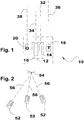
- As can be seen in
Fig. 1 to which reference is now made, a firing unit (FU) 10 in accordance with the present invention includes a directedenergy subunit 12, in which two EM beam generators coexist.EM beam generator 14 is a guide beam generator (GBG) andEM beam generator 16 is a power beam generator (PBG), shown as the larger unit. A multiplicity of FUs are synchronized by a FUs synchronization and coordination unit (FUSU), not shown. Each FU includes also two trackers, referred to as tracking subunits, atarget tracker 18 and aguide beam tracker 20.Guide beam generator 14,power beam generator 16,target tracker 18 andguide beam tracker 20 are all boresighted, meaning practically that their respective line of sights (LOSs), 32, 34, 36 and 38, all coincide on a target. - In a typical system of the present invention, the beam of GBG is a low-divergence beam, while the beam produced by the PBG can be of lower beam quality (particularly with respect to the higher divergence), but of high power.
- Once
target tracker 18 acquires a target, it sends a confirmatory signal to a control unit (not specified). Following, the FU sends a power beam to the same place on the target surface as designated by the tracker. In parallel, aguide beam generator 14 sends a beam to the above said spot on the target surface. This beam is not necessarily of high power but is required to produce a spot of EM radiation on the target. - Referring to
Fig. 2 ,several FUs 52 are shown pointing their power beams at atarget 54, meaning that theLOS 56 of their respective power beam generators track with their aim point on the target surface. - The process of intercepting a target and further inflicting damage to it is further explained with reference to the flow chart in
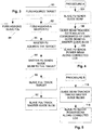
Fig. 3 . The FUSU, having a target tracker, which is typically a radar based apparatus or a thermal radiation tracker as disclosed inUS Patent 6476859 , acquires a target instep 80. Then, it assigns a master FU instep 82. An alternative is that the master FU is assigned regardless of target acquisition. Simultaneously the FUSU assigns slave FUs instep 84, an alternative to that is that all other FUs become slaves once a master has been assigned. The master FU acquires the target then atstep 86 and further sends a guide beam to the target atstep 88. The EM radiation spot created by the master guide beam can be considered as defining the center of a new local coordinate system. Atstep 90, the slave FUs track the target by using their respective target trackers, and atstep 92 they each track the EM radiation spot on the target formed by the master guide beam, this spot is hereinafter referred to as master guide spot. Such tracking is performed using the dedicated guide beam tracker, typically using an optical sensing device for guide beam implemented by means of a laser beam. - From this point onwards, there are two main possible continuation procedures according to which the task is implemented in accordance with the present invention. In procedure A, a preferred embodiment, described in
Fig. 4 , the slave FUs send each a guide beam all of which are referred to hereinafter as slave guide beams, atstep 104, to the target, so the target may show at one point in time several blobs, one for each slave FU and one for the master FU. Guide beam tracker on each FU, recognizes its respective guide spot (see below) atstep 106 and the distance between the master guide spot and its respective guide spot can be calculated. The guide beam tracker passing the information invokes the computing device to calculate the distance and direction between the spots. The resulting difference is translated into a direction, following which the power beam is sent to the target, in a corrected direction vector aiming at the center of the local coordinates system on the target, atstep 108. In an alternative procedure, related to as procedure B inFig. 5 , the slave FUs do not use their guide beams, their respective guide beam trackers track the spot produced by the master guide beam on the target instep 116. Then, having calculated the correct direction vector to the master guide beam spot, atstep 118 the slave FU sends its power beam in corrected LOS to the target. - The spot of light formed by the master guide beam has a specific signature, so that when tracked by the respective guide beam trackers of the slave FUs, they are able to differentiate this beam from the equivalent guide beams of the slave beams. Moreover all the respective spots formed by the respective guide beams on the target are to be differentiable from each other and from the master guide beam spot. In order to achieve this effect, each individual guide beam bears a specific signature. Such a signature is implemented in one or more beam features, for example specific distinct frequency, distinct amplitude modulation, or distinct frequency modulation of the pulses of the beam.
- In accordance with the present invention, for a given firing event, the FUSU may assign any available FU as a master or slave FU. In case that two or more targets are handled simultaneously, any given FU can function with regards to one target as a master and as slave with regards to a different target, concomitantly.
Claims (8)
- A method for combining power of separate directed Laser beams each associated with a separate firing unit (10, 52), on a common spot on at least one target, said method comprising the steps of:• a firing units coordination and synchronization unit, FUSU, tracking at least one target (54) and assigning at least one master firing unit, and assigning slave firing units to said at least one master firing unit for handling at least said at least one target (54);• said at least one master firing unit sending a guide beam provided by a respective beam generator (14) bearing a specific signature to said at least one target (54), producing at least one spot of Laser radiation on said at least one target (54) and forming a local coordinate system on said at least one target (54);• said slave firing units tracking said at least one target (54) using a target tracker (18);• said slave units tracking the at least one spot of Laser radiation, on said at least one target (54);• calculating a direction vector for each of said slave firing units, and• said slave firing units sending each a guide beam bearing each a specific signature to said at least one target (54), and said master unit and slave units firing each a power beam at said at least one target (54), and• wherein on each one of said firing units (52), said guide beam generator (14), said power beam generator (16) and said target tracker are all bore-sighted.
- A method as in claim 1 wherein said assigning of at least one master firing unit, and slave firing units by said FUSU precedes said tracking of a target by said FUSU.
- A method as in claim 1 wherein said slave units track spot of Laser radiation associated with master firing unit.
- A method as in claim 1 wherein said slave units track spot of Laser radiation associated with the master firing unit and other spots of Laser radiation, and wherein calculating the direction vector to said target is based upon the relations between each respective Laser spot and said spot of said master.
- A method as in claim 1 wherein said Laser radiation of at least said master firing unit bears a unique signature.
- A method as in claim 1 wherein said FUSU assigns two FUs as respective master firing units for handling two respective targets at once.
- A method as in claim 1, for a given firing event, said FUSU assigns one FUs as respective master firing units for handling one respective target and assigns a previously assigned FU as slave unit to become a master unit.
- A method as in claim 1, for a given firing event, said FUSU assigns one FUs as respective master firing units for handling one respective target and assigns said same FU as a slave unit.
Applications Claiming Priority (2)
| Application Number | Priority Date | Filing Date | Title |
|---|---|---|---|
| IL196102A IL196102A (en) | 2008-12-22 | 2008-12-22 | Laser beam unification |
| PCT/IL2010/000060 WO2010073252A2 (en) | 2008-12-22 | 2010-01-26 | Electromagnetic beams power combining |
Publications (3)
| Publication Number | Publication Date |
|---|---|
| EP2467673A2 EP2467673A2 (en) | 2012-06-27 |
| EP2467673A4 EP2467673A4 (en) | 2016-04-27 |
| EP2467673B1 true EP2467673B1 (en) | 2019-03-13 |
Family
ID=42113517
Family Applications (1)
| Application Number | Title | Priority Date | Filing Date |
|---|---|---|---|
| EP10724984.9A Active EP2467673B1 (en) | 2008-12-22 | 2010-01-26 | Electromagnetic beams power combining |
Country Status (4)
| Country | Link |
|---|---|
| US (1) | US9003942B2 (en) |
| EP (1) | EP2467673B1 (en) |
| IL (1) | IL196102A (en) |
| WO (1) | WO2010073252A2 (en) |
Families Citing this family (6)
| Publication number | Priority date | Publication date | Assignee | Title |
|---|---|---|---|---|
| FR2970072B1 (en) * | 2010-12-29 | 2013-02-08 | Thales Sa | METHOD AND DEVICE FOR NEUTRALIZING A TARGET |
| FR3035720B1 (en) * | 2015-04-30 | 2017-06-23 | Thales Sa | OPTICAL SYSTEM AND METHOD FOR LASER POINTING ACROSS THE ATMOSPHERE |
| CN117373949A (en) * | 2017-10-30 | 2024-01-09 | 应用材料公司 | Multi-zone spot heating in EPI |
| US11781835B2 (en) * | 2020-06-10 | 2023-10-10 | David H. Sitrick | Automatic weapon subsystem comprising a plurality of automated weapons subsystems |
| US11946726B2 (en) | 2022-07-26 | 2024-04-02 | General Atomics | Synchronization of high power radiofrequency sources |
| FR3152870B1 (en) * | 2023-09-13 | 2026-02-20 | Thales Sa | Target pointing device |
Family Cites Families (13)
| Publication number | Priority date | Publication date | Assignee | Title |
|---|---|---|---|---|
| US3427611A (en) * | 1962-08-15 | 1969-02-11 | Litton Industries Inc | Laser system |
| US5198607A (en) * | 1992-02-18 | 1993-03-30 | Trw Inc. | Laser anti-missle defense system |
| GB2393056B (en) | 1992-10-24 | 2004-09-01 | British Aerospace | Tracking systems |
| US5936229A (en) * | 1996-04-02 | 1999-08-10 | Trw Inc. | Tracking means for distant ballistic missile targets comprising means for tracking largest radius of curvature |
| US6066842A (en) | 1996-10-11 | 2000-05-23 | Trw Inc. | Laser along-body tracker (SABOT III) |
| EP0892240A2 (en) * | 1997-07-14 | 1999-01-20 | TRW Inc. | Forward engagement missile defense system |
| US6021975A (en) * | 1997-08-27 | 2000-02-08 | Trw Inc. | Dichroic active tracker |
| DE19743652A1 (en) | 1997-10-02 | 1999-04-08 | Diehl Stiftung & Co | Testing procedure |
| GB2350510A (en) | 1999-05-27 | 2000-11-29 | Infrared Integrated Syst Ltd | A pyroelectric sensor system having a video camera |
| US6977598B2 (en) * | 2003-03-07 | 2005-12-20 | Lockheed Martin Corporation | Aircraft protection system and method |
| FR2868847B1 (en) | 2004-04-13 | 2008-12-26 | Eads Astrium Sas Soc Par Actio | DETECTION DEVICE COMPRISING A PARABOLIC MIRROR, AND USE OF SUCH A DEVICE ABOARD AN OVERVIEW MACHINE |
| US7773202B2 (en) * | 2005-06-09 | 2010-08-10 | Analog Modules, Inc. | Laser spot tracker and target identifier |
| DE102005049539B4 (en) * | 2005-10-17 | 2008-01-17 | Diehl Bgt Defence Gmbh & Co. Kg | Method and system for disrupting or destroying an enemy device by means of high-energy radiation |
-
2008
- 2008-12-22 IL IL196102A patent/IL196102A/en active IP Right Grant
-
2010
- 2010-01-26 US US13/141,335 patent/US9003942B2/en active Active
- 2010-01-26 WO PCT/IL2010/000060 patent/WO2010073252A2/en not_active Ceased
- 2010-01-26 EP EP10724984.9A patent/EP2467673B1/en active Active
Non-Patent Citations (1)
| Title |
|---|
| None * |
Also Published As
| Publication number | Publication date |
|---|---|
| IL196102A (en) | 2016-09-29 |
| US9003942B2 (en) | 2015-04-14 |
| WO2010073252A2 (en) | 2010-07-01 |
| EP2467673A2 (en) | 2012-06-27 |
| WO2010073252A3 (en) | 2010-12-23 |
| EP2467673A4 (en) | 2016-04-27 |
| IL196102A0 (en) | 2009-12-24 |
| US20110253910A1 (en) | 2011-10-20 |
Similar Documents
| Publication | Publication Date | Title |
|---|---|---|
| EP2467673B1 (en) | Electromagnetic beams power combining | |
| US9170069B1 (en) | Aimpoint offset countermeasures for area protection | |
| EP3372946B1 (en) | Coordinating multiple ordnance targeting via optical inter-ordnance communications | |
| IL117930A (en) | Tactical laser weapon system for handling munitions | |
| US8258994B2 (en) | IR jamming system for defense against missiles with IR-sensitive homing heads | |
| EP2686634A1 (en) | Deconfliction of guided airborne weapons fired in a salvo | |
| US9423100B2 (en) | Radiating element for focussed energy | |
| US8675186B2 (en) | Systems and methods for targeting directed energy devices | |
| CN106707259A (en) | Laser radar and laser radar control method | |
| RU2635299C1 (en) | Guided weapon control method | |
| US9915504B2 (en) | Gated conjugation laser | |
| RU118045U1 (en) | ON-BOARD ACTIVE INTERFERENCE STATION FOR INDIVIDUAL PROTECTION OF AIRCRAFT AGAINST CONTROLLED ROCKETS WITH INFRARED Homing Heads | |
| RU2453794C1 (en) | Method to control high precision armament and complex of high precision armament | |
| EP4196740B1 (en) | Persistant marking of a target | |
| KR19990013454A (en) | Forward Engagement Missile Defense System | |
| GB2612033A (en) | Target tracking using background subtraction | |
| KR101364637B1 (en) | Method and apparatus for system alignment of hard-kill system | |
| US9910146B2 (en) | Measuring apparatus for measuring the trajectory of a target object | |
| RU84101U1 (en) | ACTIVE INTERFERENCE DEVICE FOR INDIVIDUAL PROTECTION OF THE AIRCRAFT AGAINST CONTROLLED ROCKETS WITH INFRARED SELF-GUIDING HEADS | |
| CN107101535B (en) | Equal focus control system for emitting laser and target detecting light | |
| RU140476U1 (en) | ON-BOARD AIRCRAFT SYSTEM OF OPTOELECTRONIC COUNTERACTION WITH INFRARED HEADS FOR CONTROLLED ROCKETS | |
| KR102926365B1 (en) | Laser target pointing device using high-speed steering mirror and system including the same | |
| Ming et al. | A cluster-based passive direction finding cross location method | |
| US9465100B2 (en) | System and method for a directable countermeasure with divergent laser | |
| RU2324139C1 (en) | Anti-aircraft short range guided missile guidance system |
Legal Events
| Date | Code | Title | Description |
|---|---|---|---|
| PUAI | Public reference made under article 153(3) epc to a published international application that has entered the european phase |
Free format text: ORIGINAL CODE: 0009012 |
|
| 17P | Request for examination filed |
Effective date: 20110721 |
|
| AK | Designated contracting states |
Kind code of ref document: A2 Designated state(s): AT BE BG CH CY CZ DE DK EE ES FI FR GB GR HR HU IE IS IT LI LT LU LV MC MK MT NL NO PL PT RO SE SI SK SM TR |
|
| REG | Reference to a national code |
Ref country code: DE Ref legal event code: R079 Ref document number: 602010057524 Country of ref document: DE Free format text: PREVIOUS MAIN CLASS: G01C0003060000 Ipc: F41H0013000000 |
|
| A4 | Supplementary search report drawn up and despatched |
Effective date: 20160330 |
|
| RIC1 | Information provided on ipc code assigned before grant |
Ipc: F41G 3/04 20060101ALI20160322BHEP Ipc: F41G 5/08 20060101ALI20160322BHEP Ipc: F41G 3/14 20060101ALI20160322BHEP Ipc: F41H 13/00 20060101AFI20160322BHEP |
|
| 17Q | First examination report despatched |
Effective date: 20160425 |
|
| GRAP | Despatch of communication of intention to grant a patent |
Free format text: ORIGINAL CODE: EPIDOSNIGR1 |
|
| STAA | Information on the status of an ep patent application or granted ep patent |
Free format text: STATUS: GRANT OF PATENT IS INTENDED |
|
| INTG | Intention to grant announced |
Effective date: 20180517 |
|
| GRAS | Grant fee paid |
Free format text: ORIGINAL CODE: EPIDOSNIGR3 |
|
| GRAJ | Information related to disapproval of communication of intention to grant by the applicant or resumption of examination proceedings by the epo deleted |
Free format text: ORIGINAL CODE: EPIDOSDIGR1 |
|
| GRAL | Information related to payment of fee for publishing/printing deleted |
Free format text: ORIGINAL CODE: EPIDOSDIGR3 |
|
| STAA | Information on the status of an ep patent application or granted ep patent |
Free format text: STATUS: EXAMINATION IS IN PROGRESS |
|
| GRAP | Despatch of communication of intention to grant a patent |
Free format text: ORIGINAL CODE: EPIDOSNIGR1 |
|
| STAA | Information on the status of an ep patent application or granted ep patent |
Free format text: STATUS: GRANT OF PATENT IS INTENDED |
|
| INTC | Intention to grant announced (deleted) | ||
| INTG | Intention to grant announced |
Effective date: 20181023 |
|
| GRAA | (expected) grant |
Free format text: ORIGINAL CODE: 0009210 |
|
| STAA | Information on the status of an ep patent application or granted ep patent |
Free format text: STATUS: THE PATENT HAS BEEN GRANTED |
|
| AK | Designated contracting states |
Kind code of ref document: B1 Designated state(s): AT BE BG CH CY CZ DE DK EE ES FI FR GB GR HR HU IE IS IT LI LT LU LV MC MK MT NL NO PL PT RO SE SI SK SM TR |
|
| REG | Reference to a national code |
Ref country code: GB Ref legal event code: FG4D |
|
| REG | Reference to a national code |
Ref country code: CH Ref legal event code: EP Ref country code: AT Ref legal event code: REF Ref document number: 1108303 Country of ref document: AT Kind code of ref document: T Effective date: 20190315 |
|
| REG | Reference to a national code |
Ref country code: IE Ref legal event code: FG4D |
|
| REG | Reference to a national code |
Ref country code: DE Ref legal event code: R096 Ref document number: 602010057524 Country of ref document: DE |
|
| REG | Reference to a national code |
Ref country code: NL Ref legal event code: FP |
|
| REG | Reference to a national code |
Ref country code: LT Ref legal event code: MG4D |
|
| PG25 | Lapsed in a contracting state [announced via postgrant information from national office to epo] |
Ref country code: LT Free format text: LAPSE BECAUSE OF FAILURE TO SUBMIT A TRANSLATION OF THE DESCRIPTION OR TO PAY THE FEE WITHIN THE PRESCRIBED TIME-LIMIT Effective date: 20190313 Ref country code: NO Free format text: LAPSE BECAUSE OF FAILURE TO SUBMIT A TRANSLATION OF THE DESCRIPTION OR TO PAY THE FEE WITHIN THE PRESCRIBED TIME-LIMIT Effective date: 20190613 Ref country code: FI Free format text: LAPSE BECAUSE OF FAILURE TO SUBMIT A TRANSLATION OF THE DESCRIPTION OR TO PAY THE FEE WITHIN THE PRESCRIBED TIME-LIMIT Effective date: 20190313 Ref country code: SE Free format text: LAPSE BECAUSE OF FAILURE TO SUBMIT A TRANSLATION OF THE DESCRIPTION OR TO PAY THE FEE WITHIN THE PRESCRIBED TIME-LIMIT Effective date: 20190313 |
|
| PG25 | Lapsed in a contracting state [announced via postgrant information from national office to epo] |
Ref country code: HR Free format text: LAPSE BECAUSE OF FAILURE TO SUBMIT A TRANSLATION OF THE DESCRIPTION OR TO PAY THE FEE WITHIN THE PRESCRIBED TIME-LIMIT Effective date: 20190313 Ref country code: GR Free format text: LAPSE BECAUSE OF FAILURE TO SUBMIT A TRANSLATION OF THE DESCRIPTION OR TO PAY THE FEE WITHIN THE PRESCRIBED TIME-LIMIT Effective date: 20190614 Ref country code: LV Free format text: LAPSE BECAUSE OF FAILURE TO SUBMIT A TRANSLATION OF THE DESCRIPTION OR TO PAY THE FEE WITHIN THE PRESCRIBED TIME-LIMIT Effective date: 20190313 Ref country code: BG Free format text: LAPSE BECAUSE OF FAILURE TO SUBMIT A TRANSLATION OF THE DESCRIPTION OR TO PAY THE FEE WITHIN THE PRESCRIBED TIME-LIMIT Effective date: 20190613 |
|
| REG | Reference to a national code |
Ref country code: AT Ref legal event code: MK05 Ref document number: 1108303 Country of ref document: AT Kind code of ref document: T Effective date: 20190313 |
|
| PG25 | Lapsed in a contracting state [announced via postgrant information from national office to epo] |
Ref country code: EE Free format text: LAPSE BECAUSE OF FAILURE TO SUBMIT A TRANSLATION OF THE DESCRIPTION OR TO PAY THE FEE WITHIN THE PRESCRIBED TIME-LIMIT Effective date: 20190313 Ref country code: SK Free format text: LAPSE BECAUSE OF FAILURE TO SUBMIT A TRANSLATION OF THE DESCRIPTION OR TO PAY THE FEE WITHIN THE PRESCRIBED TIME-LIMIT Effective date: 20190313 Ref country code: RO Free format text: LAPSE BECAUSE OF FAILURE TO SUBMIT A TRANSLATION OF THE DESCRIPTION OR TO PAY THE FEE WITHIN THE PRESCRIBED TIME-LIMIT Effective date: 20190313 Ref country code: CZ Free format text: LAPSE BECAUSE OF FAILURE TO SUBMIT A TRANSLATION OF THE DESCRIPTION OR TO PAY THE FEE WITHIN THE PRESCRIBED TIME-LIMIT Effective date: 20190313 Ref country code: ES Free format text: LAPSE BECAUSE OF FAILURE TO SUBMIT A TRANSLATION OF THE DESCRIPTION OR TO PAY THE FEE WITHIN THE PRESCRIBED TIME-LIMIT Effective date: 20190313 Ref country code: PT Free format text: LAPSE BECAUSE OF FAILURE TO SUBMIT A TRANSLATION OF THE DESCRIPTION OR TO PAY THE FEE WITHIN THE PRESCRIBED TIME-LIMIT Effective date: 20190713 Ref country code: IT Free format text: LAPSE BECAUSE OF FAILURE TO SUBMIT A TRANSLATION OF THE DESCRIPTION OR TO PAY THE FEE WITHIN THE PRESCRIBED TIME-LIMIT Effective date: 20190313 |
|
| PG25 | Lapsed in a contracting state [announced via postgrant information from national office to epo] |
Ref country code: PL Free format text: LAPSE BECAUSE OF FAILURE TO SUBMIT A TRANSLATION OF THE DESCRIPTION OR TO PAY THE FEE WITHIN THE PRESCRIBED TIME-LIMIT Effective date: 20190313 Ref country code: SM Free format text: LAPSE BECAUSE OF FAILURE TO SUBMIT A TRANSLATION OF THE DESCRIPTION OR TO PAY THE FEE WITHIN THE PRESCRIBED TIME-LIMIT Effective date: 20190313 |
|
| REG | Reference to a national code |
Ref country code: DE Ref legal event code: R097 Ref document number: 602010057524 Country of ref document: DE |
|
| PG25 | Lapsed in a contracting state [announced via postgrant information from national office to epo] |
Ref country code: AT Free format text: LAPSE BECAUSE OF FAILURE TO SUBMIT A TRANSLATION OF THE DESCRIPTION OR TO PAY THE FEE WITHIN THE PRESCRIBED TIME-LIMIT Effective date: 20190313 Ref country code: IS Free format text: LAPSE BECAUSE OF FAILURE TO SUBMIT A TRANSLATION OF THE DESCRIPTION OR TO PAY THE FEE WITHIN THE PRESCRIBED TIME-LIMIT Effective date: 20190713 |
|
| PLBE | No opposition filed within time limit |
Free format text: ORIGINAL CODE: 0009261 |
|
| STAA | Information on the status of an ep patent application or granted ep patent |
Free format text: STATUS: NO OPPOSITION FILED WITHIN TIME LIMIT |
|
| PG25 | Lapsed in a contracting state [announced via postgrant information from national office to epo] |
Ref country code: DK Free format text: LAPSE BECAUSE OF FAILURE TO SUBMIT A TRANSLATION OF THE DESCRIPTION OR TO PAY THE FEE WITHIN THE PRESCRIBED TIME-LIMIT Effective date: 20190313 |
|
| 26N | No opposition filed |
Effective date: 20191216 |
|
| PG25 | Lapsed in a contracting state [announced via postgrant information from national office to epo] |
Ref country code: SI Free format text: LAPSE BECAUSE OF FAILURE TO SUBMIT A TRANSLATION OF THE DESCRIPTION OR TO PAY THE FEE WITHIN THE PRESCRIBED TIME-LIMIT Effective date: 20190313 |
|
| PG25 | Lapsed in a contracting state [announced via postgrant information from national office to epo] |
Ref country code: TR Free format text: LAPSE BECAUSE OF FAILURE TO SUBMIT A TRANSLATION OF THE DESCRIPTION OR TO PAY THE FEE WITHIN THE PRESCRIBED TIME-LIMIT Effective date: 20190313 |
|
| PG25 | Lapsed in a contracting state [announced via postgrant information from national office to epo] |
Ref country code: MC Free format text: LAPSE BECAUSE OF FAILURE TO SUBMIT A TRANSLATION OF THE DESCRIPTION OR TO PAY THE FEE WITHIN THE PRESCRIBED TIME-LIMIT Effective date: 20190313 |
|
| REG | Reference to a national code |
Ref country code: CH Ref legal event code: PL |
|
| REG | Reference to a national code |
Ref country code: BE Ref legal event code: MM Effective date: 20200131 |
|
| PG25 | Lapsed in a contracting state [announced via postgrant information from national office to epo] |
Ref country code: FR Free format text: LAPSE BECAUSE OF NON-PAYMENT OF DUE FEES Effective date: 20200131 Ref country code: LU Free format text: LAPSE BECAUSE OF NON-PAYMENT OF DUE FEES Effective date: 20200126 |
|
| PG25 | Lapsed in a contracting state [announced via postgrant information from national office to epo] |
Ref country code: CH Free format text: LAPSE BECAUSE OF NON-PAYMENT OF DUE FEES Effective date: 20200131 Ref country code: LI Free format text: LAPSE BECAUSE OF NON-PAYMENT OF DUE FEES Effective date: 20200131 Ref country code: BE Free format text: LAPSE BECAUSE OF NON-PAYMENT OF DUE FEES Effective date: 20200131 |
|
| PG25 | Lapsed in a contracting state [announced via postgrant information from national office to epo] |
Ref country code: IE Free format text: LAPSE BECAUSE OF NON-PAYMENT OF DUE FEES Effective date: 20200126 |
|
| PG25 | Lapsed in a contracting state [announced via postgrant information from national office to epo] |
Ref country code: MT Free format text: LAPSE BECAUSE OF FAILURE TO SUBMIT A TRANSLATION OF THE DESCRIPTION OR TO PAY THE FEE WITHIN THE PRESCRIBED TIME-LIMIT Effective date: 20190313 Ref country code: CY Free format text: LAPSE BECAUSE OF FAILURE TO SUBMIT A TRANSLATION OF THE DESCRIPTION OR TO PAY THE FEE WITHIN THE PRESCRIBED TIME-LIMIT Effective date: 20190313 |
|
| PG25 | Lapsed in a contracting state [announced via postgrant information from national office to epo] |
Ref country code: MK Free format text: LAPSE BECAUSE OF FAILURE TO SUBMIT A TRANSLATION OF THE DESCRIPTION OR TO PAY THE FEE WITHIN THE PRESCRIBED TIME-LIMIT Effective date: 20190313 |
|
| PGFP | Annual fee paid to national office [announced via postgrant information from national office to epo] |
Ref country code: DE Payment date: 20241203 Year of fee payment: 16 |
|
| PGFP | Annual fee paid to national office [announced via postgrant information from national office to epo] |
Ref country code: GB Payment date: 20251204 Year of fee payment: 17 |
|
| PGFP | Annual fee paid to national office [announced via postgrant information from national office to epo] |
Ref country code: NL Payment date: 20251215 Year of fee payment: 17 |