EP2467671B1 - Dehnungsmesser und system zur räumlichen ortung derartiger messer - Google Patents
Dehnungsmesser und system zur räumlichen ortung derartiger messer Download PDFInfo
- Publication number
- EP2467671B1 EP2467671B1 EP10761054.5A EP10761054A EP2467671B1 EP 2467671 B1 EP2467671 B1 EP 2467671B1 EP 10761054 A EP10761054 A EP 10761054A EP 2467671 B1 EP2467671 B1 EP 2467671B1
- Authority
- EP
- European Patent Office
- Prior art keywords
- gauge
- structural element
- contrast
- strain gauges
- strain
- Prior art date
- Legal status (The legal status is an assumption and is not a legal conclusion. Google has not performed a legal analysis and makes no representation as to the accuracy of the status listed.)
- Not-in-force
Links
- 238000005259 measurement Methods 0.000 claims description 43
- 230000003287 optical effect Effects 0.000 claims description 17
- 239000000758 substrate Substances 0.000 claims description 13
- 238000004364 calculation method Methods 0.000 claims description 9
- 230000009471 action Effects 0.000 claims description 5
- 238000000034 method Methods 0.000 claims description 5
- 230000008859 change Effects 0.000 claims description 4
- 238000012545 processing Methods 0.000 claims description 4
- 238000012360 testing method Methods 0.000 description 7
- 238000001514 detection method Methods 0.000 description 6
- 230000001747 exhibiting effect Effects 0.000 description 4
- 241001080024 Telles Species 0.000 description 3
- 238000012550 audit Methods 0.000 description 3
- 238000013461 design Methods 0.000 description 2
- 238000002955 isolation Methods 0.000 description 2
- 239000000203 mixture Substances 0.000 description 2
- 230000001131 transforming effect Effects 0.000 description 2
- 239000000853 adhesive Substances 0.000 description 1
- 230000001070 adhesive effect Effects 0.000 description 1
- 239000000956 alloy Substances 0.000 description 1
- 229910045601 alloy Inorganic materials 0.000 description 1
- 230000008878 coupling Effects 0.000 description 1
- 238000010168 coupling process Methods 0.000 description 1
- 238000005859 coupling reaction Methods 0.000 description 1
- 238000011161 development Methods 0.000 description 1
- 229940082150 encore Drugs 0.000 description 1
- 238000009661 fatigue test Methods 0.000 description 1
- 239000002184 metal Substances 0.000 description 1
- 239000011253 protective coating Substances 0.000 description 1
- 230000004044 response Effects 0.000 description 1
- 238000004088 simulation Methods 0.000 description 1
- 230000003068 static effect Effects 0.000 description 1
- 238000012029 structural testing Methods 0.000 description 1
- 230000009466 transformation Effects 0.000 description 1
- 238000011144 upstream manufacturing Methods 0.000 description 1
- 230000000007 visual effect Effects 0.000 description 1
Images
Classifications
-
- G—PHYSICS
- G01—MEASURING; TESTING
- G01B—MEASURING LENGTH, THICKNESS OR SIMILAR LINEAR DIMENSIONS; MEASURING ANGLES; MEASURING AREAS; MEASURING IRREGULARITIES OF SURFACES OR CONTOURS
- G01B11/00—Measuring arrangements characterised by the use of optical techniques
- G01B11/002—Measuring arrangements characterised by the use of optical techniques for measuring two or more coordinates
-
- G—PHYSICS
- G01—MEASURING; TESTING
- G01B—MEASURING LENGTH, THICKNESS OR SIMILAR LINEAR DIMENSIONS; MEASURING ANGLES; MEASURING AREAS; MEASURING IRREGULARITIES OF SURFACES OR CONTOURS
- G01B7/00—Measuring arrangements characterised by the use of electric or magnetic techniques
- G01B7/16—Measuring arrangements characterised by the use of electric or magnetic techniques for measuring the deformation in a solid, e.g. by resistance strain gauge
- G01B7/18—Measuring arrangements characterised by the use of electric or magnetic techniques for measuring the deformation in a solid, e.g. by resistance strain gauge using change in resistance
-
- G—PHYSICS
- G01—MEASURING; TESTING
- G01L—MEASURING FORCE, STRESS, TORQUE, WORK, MECHANICAL POWER, MECHANICAL EFFICIENCY, OR FLUID PRESSURE
- G01L1/00—Measuring force or stress, in general
- G01L1/20—Measuring force or stress, in general by measuring variations in ohmic resistance of solid materials or of electrically-conductive fluids; by making use of electrokinetic cells, i.e. liquid-containing cells wherein an electrical potential is produced or varied upon the application of stress
- G01L1/22—Measuring force or stress, in general by measuring variations in ohmic resistance of solid materials or of electrically-conductive fluids; by making use of electrokinetic cells, i.e. liquid-containing cells wherein an electrical potential is produced or varied upon the application of stress using resistance strain gauges
- G01L1/2287—Measuring force or stress, in general by measuring variations in ohmic resistance of solid materials or of electrically-conductive fluids; by making use of electrokinetic cells, i.e. liquid-containing cells wherein an electrical potential is produced or varied upon the application of stress using resistance strain gauges constructional details of the strain gauges
-
- G—PHYSICS
- G01—MEASURING; TESTING
- G01M—TESTING STATIC OR DYNAMIC BALANCE OF MACHINES OR STRUCTURES; TESTING OF STRUCTURES OR APPARATUS, NOT OTHERWISE PROVIDED FOR
- G01M5/00—Investigating the elasticity of structures, e.g. deflection of bridges or air-craft wings
- G01M5/0016—Investigating the elasticity of structures, e.g. deflection of bridges or air-craft wings of aircraft wings or blades
-
- G—PHYSICS
- G01—MEASURING; TESTING
- G01M—TESTING STATIC OR DYNAMIC BALANCE OF MACHINES OR STRUCTURES; TESTING OF STRUCTURES OR APPARATUS, NOT OTHERWISE PROVIDED FOR
- G01M5/00—Investigating the elasticity of structures, e.g. deflection of bridges or air-craft wings
- G01M5/0091—Investigating the elasticity of structures, e.g. deflection of bridges or air-craft wings by using electromagnetic excitation or detection
-
- G—PHYSICS
- G01—MEASURING; TESTING
- G01S—RADIO DIRECTION-FINDING; RADIO NAVIGATION; DETERMINING DISTANCE OR VELOCITY BY USE OF RADIO WAVES; LOCATING OR PRESENCE-DETECTING BY USE OF THE REFLECTION OR RERADIATION OF RADIO WAVES; ANALOGOUS ARRANGEMENTS USING OTHER WAVES
- G01S17/00—Systems using the reflection or reradiation of electromagnetic waves other than radio waves, e.g. lidar systems
- G01S17/02—Systems using the reflection of electromagnetic waves other than radio waves
- G01S17/06—Systems determining position data of a target
- G01S17/46—Indirect determination of position data
Definitions
- the present invention relates to a strain gauge whose position and orientation on the surface of an object is optically detectable.
- the invention also relates to a system and a method of spatial location of such gauges placed on the surface of an object such as an aircraft structure.
- strain gauges also called strain gauges, each measuring the local deformation of the structure.
- Each of these strain gauges thus comprises an element intended to lengthen reversibly under the action of a force applied while exhibiting a variation in its resistance. This elongation takes place along a axis defining the measuring axis of the gauge. By measuring this very small variation in resistance, one can go back to the deformations occurring in the measurement zone of the gauge in the structure under test.
- gauges typically more than 1000, is required for large-scale structural testing, which requires the use of multichannel and specialized data acquisition systems.
- Each gauge must have a strictly defined position on the structure to match the calculations and be individually identified to allow the association of a measurement with a specific point area of the actual structure under test.
- the documents DE10038450 and JP09005013 describe strain gauges based on electrical resistance variation with visual alignment marks.
- the objective of the present invention is therefore to provide a strain gauge simple in its design and its operating mode, economic, allowing a precise reading of the position of the gauge on the surface of a structure and its axis of measured.
- Another object of the present invention is a system and a method of spatial location of these strain gauges placed on the external surface of an object such as an aircraft structure, simple in their design and in their operating mode, reliable and allowing an on-the-fly capture of the positions of the gauges on the surface of this object.
- the invention relates to a strain gauge comprising a support substrate of an element for reversibly elongating under the action of a force applied by exhibiting a variation of its electrical resistance, this element elongating the along a measurement axis of said gauge.
- this strain gauge comprises at least one contrast target capable of reflecting an incident light beam, said at least one contrast target being placed on the gauge in a predetermined position permitting the determination of the center and the axis. measuring said strain gauge by detecting the position of said at least one contrast target, said at least one contrast target being a retro-reflective target.
- this detection of the positions of the contrast targets, and consequently of the gauges is carried out by the projection of a light pattern emitted by a light source such as a laser source on the surface of these targets and the detection of the reflection of this luminous pattern by the structure and these targets.
- a light source such as a laser source
- the invention finally relates to a system for spatial location of strain gauges placed on the external surface of a structural element.
- This optical measurement system is a non-contact measurement system.
- autopositionné means that the system continuously calculates its own position and orientation from observations while scanning the surface geometry of the structural element. For this, the system uses a triangulation principle and integrates a sensor that captures both the 2D surface points from the reflection of the laser light pattern on the surface of the structural element and the 2D positioning elements from the observation of the positioning elements.
- the optical measuring system comprises a measurement sensor comprising a luminous pattern projector for forming a luminous pattern on the surface of said structural element at least in said observation zone, a pair of cameras for acquiring a pair of images.
- a measurement sensor comprising a luminous pattern projector for forming a luminous pattern on the surface of said structural element at least in said observation zone, a pair of cameras for acquiring a pair of images.
- an image processor for extracting from said pair of 2D images a pair of sets of 2D surface points from the light pattern and a pair of sets of 2D positioning elements from said at least a portion a set of positioning elements;
- a 3D surface point calculator for calculating a set
- the 3D handheld laser scanner marketed under the name HANDYSCAN 3D, by CREAFORM Inc., Bel-air Street, Lévis, Quebec G6V 6K9 CANADA, is particularly suitable for the implementation of the invention.
- the surface points in the observation zone obtained from the projection of a light pattern and making it possible to determine the geometry of the structural element comprise in particular the contrast targets of each gauge.
- said positioning elements are natural elements of said structural element or inserts.
- the optical measuring system comprises a wireless transmitter for transmitting the pair of 2D images of the handheld three-dimensional measurement sensor to the image processor,
- the calculation unit is connected by a link to a storage unit comprising at least one file receiving the position and the orientation of each gauge in a coordinate system connected to said structural element as well as the measurement of the variation of its resistance and possibly the identification of said gauge.
- the invention finally relates to a system for measuring the stresses of a structural element, said system comprising a set of strain gauges intended to be placed on the external surface of said structural element to detect each the stress applying to the zone of said element. structural assembly with which said strain gauge is in contact as a change in the electrical resistance of said strain gauge; and an electrical circuit unit connected to said dipstick deforming and converting said change of electrical resistance into an output signal.
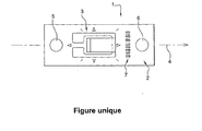
- the single figure shows a top view of a strain gauge according to a preferred embodiment of the invention.
- This strain gauge 1 comprises a substrate 2 supporting an element 3 intended to lengthen reversibly under the action of an applied stress exhibiting a variation of its resistance, this element 3 extending along an axis measuring 4 of the gauge.
- the substrate 2 may be a flexible insulating and extensible support for following the deformation of the structure, this substrate being able to be coated with a protective coating of the element 3 intended to elongate.
- This gauge 1 comprises two contrast targets 5, 6 able to reflect an incident light beam, these contrast targets 5, 6 being placed on the outer surface of the substrate 2 support in predetermined positions for the determination of the theoretical center and the measuring axis 4 of the strain gauge by the optical detection of the positions of these contrast targets 5, 6.
- These two contrast targets 5, 6 are aligned along the measurement axis 4 of the gauge and placed equidistant from the theoretical center. of this strain gauge 1 so that the detection of these targets 5, 6 makes it possible to very easily determine the position of the center and the measurement axis of this gauge 1.
- These contrast targets 5, 6 are retro-reflective circular targets.
- This detection of the positions of the contrast targets 5, 6 is advantageously achieved by the projection of a light pattern emitted by a 3D hand-held laser scanner on the surface of these targets and the detection of the reflection of this light pattern by the element. of structure and the contrast targets 5, 6 of the gauges 1.
- the gauge further comprises an identification element 7 placed on the external surface of the substrate 2, this identification element 7 making it possible to identify this gauge 1 individually.
- the identification element 7 is here a label comprising a code bars.
- An optical reader mounted on the 3D hand-held laser scanner makes it possible to simultaneously determine the position of the contrast targets 5, 6 in a coordinate system linked to the structural element of the aircraft and the identification of the gauge 1 in order to associating these measurements that are sent via a handheld 3D laser scanner wireless transmitter to a processing unit including an image processor for processing the 2D images acquired by the handheld 3D laser scanner.
- This hand-held 3D laser scanner is self-positioning and advantageously enables the positions of the contrast targets 5, 6 to be taken on the fly.
- the luminous pattern projected by this 3D laser scanner on the surface of the structural element may be a cross.
- the invention further relates to a spatial location method of strain gauges placed on the outer surface of a structural member.
- These strain gauges each comprise a support substrate of an element designed to lengthen reversibly under the action of a force applied while exhibiting a variation of its resistance, this element lengthening along a measurement axis of the gauge.
- strain gauges furthermore each comprise at least one contrast target capable of reflecting an incident light beam, these contrast targets being placed on each of these gauges in a predetermined position for determining the center and the measurement axis of the corresponding strain gauge by detecting the position of these contrast targets.
- contrast targets placed in said observation zone, the position of the center of each gauge and the orientation of said gauge in the coordinate system linked to said structural element.
- the identification element of each strain gauge placed in the observation zone is simultaneously determined.
Landscapes
- Physics & Mathematics (AREA)
- General Physics & Mathematics (AREA)
- Engineering & Computer Science (AREA)
- Electromagnetism (AREA)
- Aviation & Aerospace Engineering (AREA)
- Computer Networks & Wireless Communication (AREA)
- Radar, Positioning & Navigation (AREA)
- Remote Sensing (AREA)
- Length Measuring Devices By Optical Means (AREA)
- Measurement Of Length, Angles, Or The Like Using Electric Or Magnetic Means (AREA)
- Length Measuring Devices With Unspecified Measuring Means (AREA)
Claims (14)
- Dehnungsmessstreifen, der ein Substrat (2) enthält, das ein Element (3) trägt, welches dazu bestimmt ist, sich unter der Einwirkung einer angewendeten Kraft reversibel zu verlängern, indem es eine Änderung seines elektrischen Widerstands vorzeigt, wobei das Element (3) sich entlang einer Messachse des Messstreifens (1) verlängert, wobei der Messstreifen mindestens ein Kontrastziel (5, 6) enthält, das einen einfallenden Lichtstrahl reflektieren kann, wobei das mindestens eine Kontrastziel (5, 6) auf dem Messstreifen in einer vorbestimmten Stellung angeordnet ist, die die Festlegung der Mitte und der Messachse (4) des Dehnungsmessstreifens (1) durch die Erfassung der Stellung des mindestens einen Kontrastziels (5, 6) erlaubt, dadurch gekennzeichnet, dass das mindestens eine Kontrastziel (5, 6) ein retroreflektives Ziel ist.
- Messstreifen nach Anspruch 1, dadurch gekennzeichnet, dass er ein einziges retroreflektives Kontrastziel (5, 6) enthält, wobei das Ziel mindestens ein Markierelement aufweist, das es ermöglicht, die Messachse (4) des Dehnungsmessstreifens (1) festzulegen.
- Messstreifen nach Anspruch 1, dadurch gekennzeichnet, dass er zwei retroreflektive Kontrastziele (5, 6) enthält, die entlang der Messachse (4) ausgerichtet und in gleichem Abstand zur Mitte des Dehnungsmessstreifens (1) angeordnet sind.
- Messstreifen nach Anspruch 1, dadurch gekennzeichnet, dass er drei nicht ausgerichtete und an der Außenfläche des Substrats (2) angeordnete retroreflektive Kontrastziele enthält, um eine Festlegung der Mitte des Dehnungsmessstreifens (1) durch Triangulation zu erlauben, wobei eines der Kontrastziele (5, 6) eine andere Form und/oder andere Abmessungen als die zwei anderen Kontrastziele (5, 6) hat und auf der durch die Mitte des Messstreifens verlaufenden Messachse (4) angeordnet ist.
- Messstreifen nach einem der Ansprüche 1 bis 4, dadurch gekennzeichnet, dass die Kontrastziele (5, 6) kreisförmige retroreflektive Ziele sind.
- Messstreifen nach einem der Ansprüche 1 bis 5, dadurch gekennzeichnet, dass er außerdem ein Identifikationselement (7) aufweist, das an der Außenfläche des Substrats (2) angeordnet ist, wobei das Identifikationselement (7) es ermöglicht, den Messstreifen einzeln zu identifizieren.
- System zur räumlichen Lokalisierung von Dehnungsmessstreifen, die an der Außenfläche eines Strukturelements angeordnet sind, derart, dass:- die Dehnungsmessstreifen Dehnungsmessstreifen nach einem der Ansprüche 1 bis 6 sind,- das System ein optisches Messsystem enthält, das es ermöglicht, in einer Beobachtungszone des Systems die dreidimensionale Stellung des oder der Kontrastziele (5, 6) jedes der Dehnungsmessstreifen in einem mit dem Strukturelement verbundenen Koordinatensystem festzulegen, und- eine Recheneinheit, die es ermöglicht, ausgehend von der dreidimensionalen Stellung der in der Beobachtungszone angeordneten Kontrastziele (5, 6) die Stellung der Mitte jedes Messstreifens und die Ausrichtung des Messstreifens im mit dem Strukturelement verbundenen Koordinatensystem festzulegen.
- System nach Anspruch 7, derart dass das optische Messsystem außerdem ein Lesegerät jedes der Identifikationselemente (7) aufweist, um der Stellung der Mitte jedes Messstreifens (1) und seiner Ausrichtung im mit dem Strukturelement verbundenen Koordinatensystem eine Identifikation des Messstreifens zuzuordnen.
- System nach Anspruch 7 oder 8, derart, dass das optische Messsystem einen selbstpositionierten dreidimensionalen Handmesssensor aufweist, der einen Projektor von Laserlichtmustern, ein Paar von mindestens zwei Objektiven und Fotodetektoren, wobei dieser Sensor 2D-Bilder ausgehend von jedem Fotodetektor erzeugt, und mindestens einen Bildprozessor aufweist, um das Paar von 2D-Bildern zu verarbeiten.
- System nach Anspruch 9, derart, dass das optische Messsystem einen drahtlosen Emitter aufweist, um das Paar von 2D-Bildern vom dreidimensionalen Handmesssensor zum Bildprozessor zu übertragen.
- System nach einem der Ansprüche 7 bis 10, derart, dass die Recheneinheit über eine Verbindung mit einer Speichereinheit verbunden ist, die mindestens eine Datei enthält, die die Stellung und die Ausrichtung jedes Messstreifens in einem mit dem Strukturelement verbundenen Koordinatensystem sowie den Messwert der Änderung seines elektrischen Widerstands und ggf. die Identifikation des Messstreifens empfängt.
- Verfahren zur räumlichen Lokalisierung von an der Außenfläche eines Strukturelements angeordneten Dehnungsmessstreifen, derart, dass- die Dehnungsmessstreifen Dehnungsmessstreifen nach einem der Ansprüche 1 bis 6 sind,- ein mit dem Strukturelement verbundenes Koordinatensystem definiert wird,- an der Außenfläche des Strukturelements ein optisches Messsystem verschoben wird, das es ermöglicht, in einer Beobachtungszone des Systems die dreidimensionale Stellung des oder der retroreflektiven Kontrastziele (5, 6) jedes der Dehnungsmessstreifen im Koordinatensystem festzulegen, und- ausgehend von der dreidimensionalen Stellung der in der Beobachtungszone angeordneten retroreflektiven Kontrastziele (5, 6) die Stellung der Mitte jedes Messstreifens und die Ausrichtung des Messstreifens in einem mit dem Strukturelement verbundenen Koordinatensystem festgelegt wird.
- Lokalisierungsverfahren nach Anspruch 12, dadurch gekennzeichnet, dass gleichzeitig das Identifikationselement (7) jedes der Dehnungsmessstreifen festgelegt wird, die in der Beobachtungszone angeordnet sind.
- System zur Messung von Belastungen eines Strukturelements, wobei das System eine Einheit von Dehnungsmessstreifen, die dazu bestimmt sind, an der Außenfläche des Strukturelements angeordnet zu werden, um je die Dehnung, die an die Zone des Strukturelements angewendet wird, mit der der Dehnungsmessstreifen in Kontakt ist, als eine Änderung des elektrischen Widerstands des Dehnungsmessstreifens zu erfassen; und eine elektrische Schaltungseinheit enthält, die mit dem Dehnungsmessstreifen verbunden ist und die Änderung des elektrischen Widerstands in ein Ausgangssignal umwandelt, dadurch gekennzeichnet, dass- die Dehnungsmessstreifen Dehnungsmessstreifen nach einem der Ansprüche 1 bis 6 sind,- das System ein optisches Messsystem enthält, das es ermöglicht, in einer Beobachtungszone des Systems die dreidimensionale Stellung des oder der retroreflektiven Kontrastziele (5, 6) jedes der Dehnungsmessstreifen in einem mit dem Strukturelement verbundenen Koordinatensystem festzulegen, und- eine Recheneinheit, die es ermöglicht, ausgehend von der dreidimensionalen Stellung der in der Beobachtungszone angeordneten Kontrastziele (5, 6) die Stellung der Mitte jedes Messstreifens und die Ausrichtung des Messstreifens in dem mit dem Strukturelement verbundenen Koordinatensystem festzulegen.
Applications Claiming Priority (2)
| Application Number | Priority Date | Filing Date | Title |
|---|---|---|---|
| FR0955694A FR2949152A1 (fr) | 2009-08-17 | 2009-08-17 | Jauge de deformation et systeme de localisation spatiale de telles jauges |
| PCT/FR2010/051708 WO2011020968A1 (fr) | 2009-08-17 | 2010-08-12 | Jauge de déformation et système de localisation spatiale de telles jauges |
Publications (2)
| Publication Number | Publication Date |
|---|---|
| EP2467671A1 EP2467671A1 (de) | 2012-06-27 |
| EP2467671B1 true EP2467671B1 (de) | 2014-03-05 |
Family
ID=41478478
Family Applications (1)
| Application Number | Title | Priority Date | Filing Date |
|---|---|---|---|
| EP10761054.5A Not-in-force EP2467671B1 (de) | 2009-08-17 | 2010-08-12 | Dehnungsmesser und system zur räumlichen ortung derartiger messer |
Country Status (10)
| Country | Link |
|---|---|
| US (1) | US9200889B2 (de) |
| EP (1) | EP2467671B1 (de) |
| CN (1) | CN102549376B (de) |
| BR (1) | BR112012003736A2 (de) |
| CA (1) | CA2770597A1 (de) |
| ES (1) | ES2469851T3 (de) |
| FR (1) | FR2949152A1 (de) |
| IN (1) | IN2012DN01294A (de) |
| RU (1) | RU2596064C2 (de) |
| WO (1) | WO2011020968A1 (de) |
Families Citing this family (30)
| Publication number | Priority date | Publication date | Assignee | Title |
|---|---|---|---|---|
| US9631923B2 (en) * | 2014-09-22 | 2017-04-25 | The Boeing Company | Real-time non-linear optical strain gauge system |
| CN104634249B (zh) * | 2015-02-06 | 2017-08-29 | 南京理工大学 | 推进剂加注过程中运载火箭运动信号探测定位方法 |
| CN104677531B (zh) * | 2015-03-05 | 2017-03-01 | 西安电子科技大学 | 基于混合特征选择算法的飞机机翼载荷实测方法 |
| US9909860B2 (en) | 2015-04-15 | 2018-03-06 | General Electric Company | Systems and methods for monitoring component deformation |
| US9557164B2 (en) | 2015-04-15 | 2017-01-31 | General Electric Company | Data acquisition devices, systems and method for analyzing strain sensors and monitoring turbine component strain |
| US10697760B2 (en) | 2015-04-15 | 2020-06-30 | General Electric Company | Data acquisition devices, systems and method for analyzing strain sensors and monitoring component strain |
| US9932853B2 (en) | 2015-04-28 | 2018-04-03 | General Electric Company | Assemblies and methods for monitoring turbine component strain |
| CN105136345A (zh) * | 2015-08-21 | 2015-12-09 | 河海大学 | 一种手持式应力检测仪及其检测方法 |
| US10641672B2 (en) | 2015-09-24 | 2020-05-05 | Silicon Microstructures, Inc. | Manufacturing catheter sensors |
| US10041851B2 (en) * | 2015-09-24 | 2018-08-07 | Silicon Microstructures, Inc. | Manufacturing catheter sensors |
| US10682498B2 (en) | 2015-09-24 | 2020-06-16 | Silicon Microstructures, Inc. | Light shields for catheter sensors |
| FR3043194B1 (fr) * | 2015-11-02 | 2019-04-19 | Mesure-Systems3D | Dispositif de controle tridimensionnel sans contact de pale pour turbomachine, en particulier pour reacteur ou turbine d’aeronef |
| US9846933B2 (en) | 2015-11-16 | 2017-12-19 | General Electric Company | Systems and methods for monitoring components |
| US9953408B2 (en) | 2015-11-16 | 2018-04-24 | General Electric Company | Methods for monitoring components |
| US10012552B2 (en) | 2015-11-23 | 2018-07-03 | General Electric Company | Systems and methods for monitoring component strain |
| CN105424721B (zh) * | 2015-12-11 | 2018-07-13 | 南京神源生智能科技有限公司 | 一种金属应变计缺陷自动检测系统 |
| US9967523B2 (en) | 2015-12-16 | 2018-05-08 | General Electric Company | Locating systems and methods for components |
| US9879981B1 (en) | 2016-12-02 | 2018-01-30 | General Electric Company | Systems and methods for evaluating component strain |
| US10132615B2 (en) | 2016-12-20 | 2018-11-20 | General Electric Company | Data acquisition devices, systems and method for analyzing passive strain indicators and monitoring turbine component strain |
| US10126119B2 (en) | 2017-01-17 | 2018-11-13 | General Electric Company | Methods of forming a passive strain indicator on a preexisting component |
| US10872176B2 (en) | 2017-01-23 | 2020-12-22 | General Electric Company | Methods of making and monitoring a component with an integral strain indicator |
| US11313673B2 (en) | 2017-01-24 | 2022-04-26 | General Electric Company | Methods of making a component with an integral strain indicator |
| US10345179B2 (en) | 2017-02-14 | 2019-07-09 | General Electric Company | Passive strain indicator |
| US20180238755A1 (en) * | 2017-02-21 | 2018-08-23 | General Electric Company | Methods of Making and Monitoring Components with Integral Strain Indicators |
| US10502551B2 (en) | 2017-03-06 | 2019-12-10 | General Electric Company | Methods for monitoring components using micro and macro three-dimensional analysis |
| US10451499B2 (en) | 2017-04-06 | 2019-10-22 | General Electric Company | Methods for applying passive strain indicators to components |
| US20220380658A1 (en) | 2019-10-31 | 2022-12-01 | Chevron Oronite Company Llc | Functionalized olefin oligomers |
| DE102019219387A1 (de) * | 2019-12-11 | 2021-06-17 | MTU Aero Engines AG | Verfahren und vorrichtung zum bestimmen von aufwertefaktoren für dehnungsmessungen an maschinenelementen |
| CN114820789B (zh) * | 2022-04-26 | 2025-02-07 | 陕西新高斯激光科技有限公司 | 一种不规则目标智能识别及定位方法与系统 |
| US20240060835A1 (en) * | 2022-08-22 | 2024-02-22 | The Boeing Company | System and method for identifying optimal locations for strain gage placement on a structure |
Citations (1)
| Publication number | Priority date | Publication date | Assignee | Title |
|---|---|---|---|---|
| FR2706045A1 (fr) * | 1993-06-04 | 1994-12-09 | Espace Ind Controles | Cible rétro-réfléchissante et son procédé de fabrication. |
Family Cites Families (11)
| Publication number | Priority date | Publication date | Assignee | Title |
|---|---|---|---|---|
| GB1414145A (en) * | 1972-05-11 | 1975-11-19 | Vickers Ltd | Optical devices |
| US4123158A (en) * | 1975-05-09 | 1978-10-31 | Reytblatt Zinovy V | Photoelastic strain gauge |
| DE4204521C1 (de) * | 1992-02-15 | 1993-06-24 | Daimler-Benz Aktiengesellschaft, 7000 Stuttgart, De | |
| JPH095013A (ja) * | 1995-06-22 | 1997-01-10 | Ishikawajima Harima Heavy Ind Co Ltd | 定点目盛付きひずみゲージ |
| JP4794708B2 (ja) * | 1999-02-04 | 2011-10-19 | オリンパス株式会社 | 3次元位置姿勢センシング装置 |
| DE10038450A1 (de) * | 2000-08-07 | 2002-02-21 | Hbm Mes Und Systemtechnik Gmbh | Dehnungsmeßstreifen und Verfahren zum Positionieren von Dehnungsmeßstreifen auf einem Dehnungskörper |
| CA2600926C (en) * | 2005-03-11 | 2009-06-09 | Creaform Inc. | Auto-referenced system and apparatus for three-dimensional scanning |
| US7434480B2 (en) * | 2005-12-14 | 2008-10-14 | The Boeing Company | Methods and systems for using active surface coverings for structural assessment and monitoring |
| EP1914684A1 (de) * | 2006-10-17 | 2008-04-23 | Jose Maria De Espona Delgado | Identizierungsetikett welches grafische und/oder elektromagnetische Referenzen enthält um eine Beziehung zwischen einer dreidimensionalen Form und einem realen Objekt herzustellen, und ein Verfahren welchen dieses benutzt |
| JP2009047501A (ja) * | 2007-08-17 | 2009-03-05 | Ricoh Co Ltd | 光学式歪測定素子、装置、システムおよび方法 |
| DE112010003179B4 (de) * | 2009-09-18 | 2016-12-29 | Illinois Tool Works, Inc. | Optische Verschiebungsmessvorrichtung und Verfahren zur Messung einer Verschiebung |
-
2009
- 2009-08-17 FR FR0955694A patent/FR2949152A1/fr not_active Withdrawn
-
2010
- 2010-08-12 CN CN201080036588.6A patent/CN102549376B/zh not_active Expired - Fee Related
- 2010-08-12 US US13/389,485 patent/US9200889B2/en not_active Expired - Fee Related
- 2010-08-12 EP EP10761054.5A patent/EP2467671B1/de not_active Not-in-force
- 2010-08-12 CA CA2770597A patent/CA2770597A1/fr not_active Abandoned
- 2010-08-12 RU RU2012105634/28A patent/RU2596064C2/ru not_active IP Right Cessation
- 2010-08-12 IN IN1294DEN2012 patent/IN2012DN01294A/en unknown
- 2010-08-12 BR BR112012003736A patent/BR112012003736A2/pt not_active IP Right Cessation
- 2010-08-12 WO PCT/FR2010/051708 patent/WO2011020968A1/fr not_active Ceased
- 2010-08-12 ES ES10761054.5T patent/ES2469851T3/es active Active
Patent Citations (1)
| Publication number | Priority date | Publication date | Assignee | Title |
|---|---|---|---|---|
| FR2706045A1 (fr) * | 1993-06-04 | 1994-12-09 | Espace Ind Controles | Cible rétro-réfléchissante et son procédé de fabrication. |
Also Published As
| Publication number | Publication date |
|---|---|
| EP2467671A1 (de) | 2012-06-27 |
| RU2596064C2 (ru) | 2016-08-27 |
| FR2949152A1 (fr) | 2011-02-18 |
| ES2469851T3 (es) | 2014-06-20 |
| CN102549376A (zh) | 2012-07-04 |
| RU2012105634A (ru) | 2013-10-27 |
| WO2011020968A1 (fr) | 2011-02-24 |
| US20120147384A1 (en) | 2012-06-14 |
| US9200889B2 (en) | 2015-12-01 |
| IN2012DN01294A (de) | 2015-06-05 |
| CA2770597A1 (fr) | 2011-02-24 |
| BR112012003736A2 (pt) | 2016-04-12 |
| CN102549376B (zh) | 2016-08-17 |
Similar Documents
| Publication | Publication Date | Title |
|---|---|---|
| EP2467671B1 (de) | Dehnungsmesser und system zur räumlichen ortung derartiger messer | |
| Poozesh et al. | Large-area photogrammetry based testing of wind turbine blades | |
| Poozesh et al. | Multicamera measurement system to evaluate the dynamic response of utility‐scale wind turbine blades | |
| Aubreton et al. | Infrared system for 3D scanning of metallic surfaces | |
| EP3428572B1 (de) | Filmdicken-messverfahren und filmdicken-messvorrichtung | |
| CN102077053A (zh) | 用于把超声数据映射到cad空间的视觉系统和方法 | |
| US20100208062A1 (en) | Method and device for exact measurement of objects | |
| US8818755B2 (en) | Container thickness measuring systems and methods | |
| CN101666640B (zh) | 一种二维姿态角的测量方法和系统 | |
| TW200842308A (en) | One diffraction 6 degree of freedom optoelectronic measurement system | |
| CN102506759A (zh) | 一种大口径非球面朗奇检测方法 | |
| CN103759675A (zh) | 一种用于光学元件非球面微结构的同步检测方法 | |
| CN201096611Y (zh) | 一种非球面透镜的偏心测量装置 | |
| CN105674904B (zh) | 一种具有智能化装配特点的汽轮机通流间隙检测方法 | |
| CN102095386A (zh) | 一种二维小角度激光视觉精密测量装置及其实现方法 | |
| EP2864742B1 (de) | Seriell adressierter unterpupillenschirm für in-situ-wellenfrontmessung eines elektrooptischen sensors | |
| TW201120401A (en) | Contact-less optical composite measurement method and system thereof. | |
| CN101221089A (zh) | 一种空间反射型光学遥感器主镜面形畸变探测方法及系统 | |
| Zheng et al. | A non-contact swing-arm profilometer with the spectrally-resolved-interferometry distance sensor | |
| US20110193954A1 (en) | Apparatus for the measurement of the topography and photoelectric properties of transparent surfaces | |
| CN201731943U (zh) | 一种波长识别装置 | |
| Liu et al. | Optical challenging feature inline measurement system based on photometric stereo and HON feature extractor | |
| TW200842320A (en) | One optoelectronic 6 degree of freedom measurement system based multi-reflection principle | |
| Oliva et al. | Twyman–Green-type integrated laser interferometer array for parallel MEMS testing | |
| TW200842307A (en) | One optoelectronic 6 degree of freedom measurement system |
Legal Events
| Date | Code | Title | Description |
|---|---|---|---|
| PUAI | Public reference made under article 153(3) epc to a published international application that has entered the european phase |
Free format text: ORIGINAL CODE: 0009012 |
|
| 17P | Request for examination filed |
Effective date: 20120224 |
|
| AK | Designated contracting states |
Kind code of ref document: A1 Designated state(s): AL AT BE BG CH CY CZ DE DK EE ES FI FR GB GR HR HU IE IS IT LI LT LU LV MC MK MT NL NO PL PT RO SE SI SK SM TR |
|
| DAX | Request for extension of the european patent (deleted) | ||
| REG | Reference to a national code |
Ref country code: DE Ref legal event code: R079 Ref document number: 602010014017 Country of ref document: DE Free format text: PREVIOUS MAIN CLASS: G01B0007160000 Ipc: G01M0005000000 |
|
| RIC1 | Information provided on ipc code assigned before grant |
Ipc: G01B 11/02 20060101ALI20121129BHEP Ipc: G01M 5/00 20060101AFI20121129BHEP Ipc: G01B 7/16 20060101ALI20121129BHEP Ipc: G01S 17/46 20060101ALI20121129BHEP Ipc: G01S 17/06 20060101ALI20121129BHEP Ipc: G01L 1/22 20060101ALI20121129BHEP Ipc: G01B 11/16 20060101ALI20121129BHEP |
|
| 17Q | First examination report despatched |
Effective date: 20121214 |
|
| GRAP | Despatch of communication of intention to grant a patent |
Free format text: ORIGINAL CODE: EPIDOSNIGR1 |
|
| INTG | Intention to grant announced |
Effective date: 20130927 |
|
| GRAS | Grant fee paid |
Free format text: ORIGINAL CODE: EPIDOSNIGR3 |
|
| GRAA | (expected) grant |
Free format text: ORIGINAL CODE: 0009210 |
|
| AK | Designated contracting states |
Kind code of ref document: B1 Designated state(s): AL AT BE BG CH CY CZ DE DK EE ES FI FR GB GR HR HU IE IS IT LI LT LU LV MC MK MT NL NO PL PT RO SE SI SK SM TR |
|
| REG | Reference to a national code |
Ref country code: GB Ref legal event code: FG4D Free format text: NOT ENGLISH |
|
| REG | Reference to a national code |
Ref country code: CH Ref legal event code: EP |
|
| REG | Reference to a national code |
Ref country code: AT Ref legal event code: REF Ref document number: 655196 Country of ref document: AT Kind code of ref document: T Effective date: 20140315 |
|
| REG | Reference to a national code |
Ref country code: IE Ref legal event code: FG4D Free format text: LANGUAGE OF EP DOCUMENT: FRENCH |
|
| REG | Reference to a national code |
Ref country code: DE Ref legal event code: R096 Ref document number: 602010014017 Country of ref document: DE Effective date: 20140417 |
|
| REG | Reference to a national code |
Ref country code: ES Ref legal event code: FG2A Ref document number: 2469851 Country of ref document: ES Kind code of ref document: T3 Effective date: 20140620 |
|
| REG | Reference to a national code |
Ref country code: AT Ref legal event code: MK05 Ref document number: 655196 Country of ref document: AT Kind code of ref document: T Effective date: 20140305 |
|
| REG | Reference to a national code |
Ref country code: NL Ref legal event code: VDEP Effective date: 20140305 |
|
| PG25 | Lapsed in a contracting state [announced via postgrant information from national office to epo] |
Ref country code: NO Free format text: LAPSE BECAUSE OF FAILURE TO SUBMIT A TRANSLATION OF THE DESCRIPTION OR TO PAY THE FEE WITHIN THE PRESCRIBED TIME-LIMIT Effective date: 20140605 Ref country code: LT Free format text: LAPSE BECAUSE OF FAILURE TO SUBMIT A TRANSLATION OF THE DESCRIPTION OR TO PAY THE FEE WITHIN THE PRESCRIBED TIME-LIMIT Effective date: 20140305 |
|
| REG | Reference to a national code |
Ref country code: LT Ref legal event code: MG4D |
|
| PG25 | Lapsed in a contracting state [announced via postgrant information from national office to epo] |
Ref country code: CY Free format text: LAPSE BECAUSE OF FAILURE TO SUBMIT A TRANSLATION OF THE DESCRIPTION OR TO PAY THE FEE WITHIN THE PRESCRIBED TIME-LIMIT Effective date: 20140305 Ref country code: FI Free format text: LAPSE BECAUSE OF FAILURE TO SUBMIT A TRANSLATION OF THE DESCRIPTION OR TO PAY THE FEE WITHIN THE PRESCRIBED TIME-LIMIT Effective date: 20140305 Ref country code: SE Free format text: LAPSE BECAUSE OF FAILURE TO SUBMIT A TRANSLATION OF THE DESCRIPTION OR TO PAY THE FEE WITHIN THE PRESCRIBED TIME-LIMIT Effective date: 20140305 Ref country code: AT Free format text: LAPSE BECAUSE OF FAILURE TO SUBMIT A TRANSLATION OF THE DESCRIPTION OR TO PAY THE FEE WITHIN THE PRESCRIBED TIME-LIMIT Effective date: 20140305 |
|
| PG25 | Lapsed in a contracting state [announced via postgrant information from national office to epo] |
Ref country code: LV Free format text: LAPSE BECAUSE OF FAILURE TO SUBMIT A TRANSLATION OF THE DESCRIPTION OR TO PAY THE FEE WITHIN THE PRESCRIBED TIME-LIMIT Effective date: 20140305 Ref country code: HR Free format text: LAPSE BECAUSE OF FAILURE TO SUBMIT A TRANSLATION OF THE DESCRIPTION OR TO PAY THE FEE WITHIN THE PRESCRIBED TIME-LIMIT Effective date: 20140305 |
|
| PG25 | Lapsed in a contracting state [announced via postgrant information from national office to epo] |
Ref country code: EE Free format text: LAPSE BECAUSE OF FAILURE TO SUBMIT A TRANSLATION OF THE DESCRIPTION OR TO PAY THE FEE WITHIN THE PRESCRIBED TIME-LIMIT Effective date: 20140305 Ref country code: RO Free format text: LAPSE BECAUSE OF FAILURE TO SUBMIT A TRANSLATION OF THE DESCRIPTION OR TO PAY THE FEE WITHIN THE PRESCRIBED TIME-LIMIT Effective date: 20140305 Ref country code: IS Free format text: LAPSE BECAUSE OF FAILURE TO SUBMIT A TRANSLATION OF THE DESCRIPTION OR TO PAY THE FEE WITHIN THE PRESCRIBED TIME-LIMIT Effective date: 20140705 Ref country code: BG Free format text: LAPSE BECAUSE OF FAILURE TO SUBMIT A TRANSLATION OF THE DESCRIPTION OR TO PAY THE FEE WITHIN THE PRESCRIBED TIME-LIMIT Effective date: 20140605 Ref country code: NL Free format text: LAPSE BECAUSE OF FAILURE TO SUBMIT A TRANSLATION OF THE DESCRIPTION OR TO PAY THE FEE WITHIN THE PRESCRIBED TIME-LIMIT Effective date: 20140305 Ref country code: CZ Free format text: LAPSE BECAUSE OF FAILURE TO SUBMIT A TRANSLATION OF THE DESCRIPTION OR TO PAY THE FEE WITHIN THE PRESCRIBED TIME-LIMIT Effective date: 20140305 |
|
| PGFP | Annual fee paid to national office [announced via postgrant information from national office to epo] |
Ref country code: DE Payment date: 20140821 Year of fee payment: 5 |
|
| PG25 | Lapsed in a contracting state [announced via postgrant information from national office to epo] |
Ref country code: PL Free format text: LAPSE BECAUSE OF FAILURE TO SUBMIT A TRANSLATION OF THE DESCRIPTION OR TO PAY THE FEE WITHIN THE PRESCRIBED TIME-LIMIT Effective date: 20140305 Ref country code: SK Free format text: LAPSE BECAUSE OF FAILURE TO SUBMIT A TRANSLATION OF THE DESCRIPTION OR TO PAY THE FEE WITHIN THE PRESCRIBED TIME-LIMIT Effective date: 20140305 |
|
| PGFP | Annual fee paid to national office [announced via postgrant information from national office to epo] |
Ref country code: GB Payment date: 20140820 Year of fee payment: 5 Ref country code: ES Payment date: 20140826 Year of fee payment: 5 |
|
| REG | Reference to a national code |
Ref country code: DE Ref legal event code: R097 Ref document number: 602010014017 Country of ref document: DE |
|
| PG25 | Lapsed in a contracting state [announced via postgrant information from national office to epo] |
Ref country code: PT Free format text: LAPSE BECAUSE OF FAILURE TO SUBMIT A TRANSLATION OF THE DESCRIPTION OR TO PAY THE FEE WITHIN THE PRESCRIBED TIME-LIMIT Effective date: 20140707 |
|
| PGFP | Annual fee paid to national office [announced via postgrant information from national office to epo] |
Ref country code: IT Payment date: 20140822 Year of fee payment: 5 |
|
| PLBE | No opposition filed within time limit |
Free format text: ORIGINAL CODE: 0009261 |
|
| STAA | Information on the status of an ep patent application or granted ep patent |
Free format text: STATUS: NO OPPOSITION FILED WITHIN TIME LIMIT |
|
| PG25 | Lapsed in a contracting state [announced via postgrant information from national office to epo] |
Ref country code: DK Free format text: LAPSE BECAUSE OF FAILURE TO SUBMIT A TRANSLATION OF THE DESCRIPTION OR TO PAY THE FEE WITHIN THE PRESCRIBED TIME-LIMIT Effective date: 20140305 |
|
| 26N | No opposition filed |
Effective date: 20141208 |
|
| REG | Reference to a national code |
Ref country code: DE Ref legal event code: R097 Ref document number: 602010014017 Country of ref document: DE Effective date: 20141208 |
|
| PG25 | Lapsed in a contracting state [announced via postgrant information from national office to epo] |
Ref country code: LU Free format text: LAPSE BECAUSE OF FAILURE TO SUBMIT A TRANSLATION OF THE DESCRIPTION OR TO PAY THE FEE WITHIN THE PRESCRIBED TIME-LIMIT Effective date: 20140812 Ref country code: MC Free format text: LAPSE BECAUSE OF FAILURE TO SUBMIT A TRANSLATION OF THE DESCRIPTION OR TO PAY THE FEE WITHIN THE PRESCRIBED TIME-LIMIT Effective date: 20140305 |
|
| REG | Reference to a national code |
Ref country code: CH Ref legal event code: PL |
|
| PG25 | Lapsed in a contracting state [announced via postgrant information from national office to epo] |
Ref country code: BE Free format text: LAPSE BECAUSE OF NON-PAYMENT OF DUE FEES Effective date: 20140831 Ref country code: LI Free format text: LAPSE BECAUSE OF NON-PAYMENT OF DUE FEES Effective date: 20140831 Ref country code: CH Free format text: LAPSE BECAUSE OF NON-PAYMENT OF DUE FEES Effective date: 20140831 |
|
| REG | Reference to a national code |
Ref country code: IE Ref legal event code: MM4A |
|
| PG25 | Lapsed in a contracting state [announced via postgrant information from national office to epo] |
Ref country code: SI Free format text: LAPSE BECAUSE OF FAILURE TO SUBMIT A TRANSLATION OF THE DESCRIPTION OR TO PAY THE FEE WITHIN THE PRESCRIBED TIME-LIMIT Effective date: 20140305 |
|
| PG25 | Lapsed in a contracting state [announced via postgrant information from national office to epo] |
Ref country code: IE Free format text: LAPSE BECAUSE OF NON-PAYMENT OF DUE FEES Effective date: 20140812 |
|
| REG | Reference to a national code |
Ref country code: DE Ref legal event code: R119 Ref document number: 602010014017 Country of ref document: DE |
|
| GBPC | Gb: european patent ceased through non-payment of renewal fee |
Effective date: 20150812 |
|
| PG25 | Lapsed in a contracting state [announced via postgrant information from national office to epo] |
Ref country code: SM Free format text: LAPSE BECAUSE OF FAILURE TO SUBMIT A TRANSLATION OF THE DESCRIPTION OR TO PAY THE FEE WITHIN THE PRESCRIBED TIME-LIMIT Effective date: 20140305 Ref country code: IT Free format text: LAPSE BECAUSE OF NON-PAYMENT OF DUE FEES Effective date: 20150812 |
|
| PG25 | Lapsed in a contracting state [announced via postgrant information from national office to epo] |
Ref country code: GR Free format text: LAPSE BECAUSE OF FAILURE TO SUBMIT A TRANSLATION OF THE DESCRIPTION OR TO PAY THE FEE WITHIN THE PRESCRIBED TIME-LIMIT Effective date: 20140606 Ref country code: MT Free format text: LAPSE BECAUSE OF FAILURE TO SUBMIT A TRANSLATION OF THE DESCRIPTION OR TO PAY THE FEE WITHIN THE PRESCRIBED TIME-LIMIT Effective date: 20140305 |
|
| PG25 | Lapsed in a contracting state [announced via postgrant information from national office to epo] |
Ref country code: HU Free format text: LAPSE BECAUSE OF FAILURE TO SUBMIT A TRANSLATION OF THE DESCRIPTION OR TO PAY THE FEE WITHIN THE PRESCRIBED TIME-LIMIT; INVALID AB INITIO Effective date: 20100812 Ref country code: DE Free format text: LAPSE BECAUSE OF NON-PAYMENT OF DUE FEES Effective date: 20160301 Ref country code: TR Free format text: LAPSE BECAUSE OF FAILURE TO SUBMIT A TRANSLATION OF THE DESCRIPTION OR TO PAY THE FEE WITHIN THE PRESCRIBED TIME-LIMIT Effective date: 20140305 Ref country code: GB Free format text: LAPSE BECAUSE OF NON-PAYMENT OF DUE FEES Effective date: 20150812 |
|
| REG | Reference to a national code |
Ref country code: FR Ref legal event code: PLFP Year of fee payment: 7 |
|
| REG | Reference to a national code |
Ref country code: ES Ref legal event code: FD2A Effective date: 20160926 |
|
| PG25 | Lapsed in a contracting state [announced via postgrant information from national office to epo] |
Ref country code: ES Free format text: LAPSE BECAUSE OF NON-PAYMENT OF DUE FEES Effective date: 20150813 |
|
| REG | Reference to a national code |
Ref country code: FR Ref legal event code: PLFP Year of fee payment: 8 |
|
| PG25 | Lapsed in a contracting state [announced via postgrant information from national office to epo] |
Ref country code: MK Free format text: LAPSE BECAUSE OF FAILURE TO SUBMIT A TRANSLATION OF THE DESCRIPTION OR TO PAY THE FEE WITHIN THE PRESCRIBED TIME-LIMIT Effective date: 20140305 |
|
| REG | Reference to a national code |
Ref country code: FR Ref legal event code: PLFP Year of fee payment: 9 |
|
| PG25 | Lapsed in a contracting state [announced via postgrant information from national office to epo] |
Ref country code: AL Free format text: LAPSE BECAUSE OF FAILURE TO SUBMIT A TRANSLATION OF THE DESCRIPTION OR TO PAY THE FEE WITHIN THE PRESCRIBED TIME-LIMIT Effective date: 20140305 |
|
| PGFP | Annual fee paid to national office [announced via postgrant information from national office to epo] |
Ref country code: FR Payment date: 20200821 Year of fee payment: 11 |
|
| PG25 | Lapsed in a contracting state [announced via postgrant information from national office to epo] |
Ref country code: FR Free format text: LAPSE BECAUSE OF NON-PAYMENT OF DUE FEES Effective date: 20210831 |