EP2467641B1 - Optical flue gas monitor and control - Google Patents
Optical flue gas monitor and control Download PDFInfo
- Publication number
- EP2467641B1 EP2467641B1 EP10742057.2A EP10742057A EP2467641B1 EP 2467641 B1 EP2467641 B1 EP 2467641B1 EP 10742057 A EP10742057 A EP 10742057A EP 2467641 B1 EP2467641 B1 EP 2467641B1
- Authority
- EP
- European Patent Office
- Prior art keywords
- control system
- constituent
- monitoring device
- downstream
- concentration
- Prior art date
- Legal status (The legal status is an assumption and is not a legal conclusion. Google has not performed a legal analysis and makes no representation as to the accuracy of the status listed.)
- Not-in-force
Links
Images

Classifications
-
- F—MECHANICAL ENGINEERING; LIGHTING; HEATING; WEAPONS; BLASTING
- F23—COMBUSTION APPARATUS; COMBUSTION PROCESSES
- F23J—REMOVAL OR TREATMENT OF COMBUSTION PRODUCTS OR COMBUSTION RESIDUES; FLUES
- F23J15/00—Arrangements of devices for treating smoke or fumes
-
- F—MECHANICAL ENGINEERING; LIGHTING; HEATING; WEAPONS; BLASTING
- F23—COMBUSTION APPARATUS; COMBUSTION PROCESSES
- F23D—BURNERS
- F23D1/00—Burners for combustion of pulverulent fuel
- F23D1/02—Vortex burners, e.g. for cyclone-type combustion apparatus
-
- F—MECHANICAL ENGINEERING; LIGHTING; HEATING; WEAPONS; BLASTING
- F23—COMBUSTION APPARATUS; COMBUSTION PROCESSES
- F23J—REMOVAL OR TREATMENT OF COMBUSTION PRODUCTS OR COMBUSTION RESIDUES; FLUES
- F23J15/00—Arrangements of devices for treating smoke or fumes
- F23J15/003—Arrangements of devices for treating smoke or fumes for supplying chemicals to fumes, e.g. using injection devices
-
- F—MECHANICAL ENGINEERING; LIGHTING; HEATING; WEAPONS; BLASTING
- F23—COMBUSTION APPARATUS; COMBUSTION PROCESSES
- F23J—REMOVAL OR TREATMENT OF COMBUSTION PRODUCTS OR COMBUSTION RESIDUES; FLUES
- F23J15/00—Arrangements of devices for treating smoke or fumes
- F23J15/02—Arrangements of devices for treating smoke or fumes of purifiers, e.g. for removing noxious material
- F23J15/022—Arrangements of devices for treating smoke or fumes of purifiers, e.g. for removing noxious material for removing solid particulate material from the gasflow
-
- F—MECHANICAL ENGINEERING; LIGHTING; HEATING; WEAPONS; BLASTING
- F23—COMBUSTION APPARATUS; COMBUSTION PROCESSES
- F23J—REMOVAL OR TREATMENT OF COMBUSTION PRODUCTS OR COMBUSTION RESIDUES; FLUES
- F23J15/00—Arrangements of devices for treating smoke or fumes
- F23J15/02—Arrangements of devices for treating smoke or fumes of purifiers, e.g. for removing noxious material
- F23J15/04—Arrangements of devices for treating smoke or fumes of purifiers, e.g. for removing noxious material using washing fluids
-
- F—MECHANICAL ENGINEERING; LIGHTING; HEATING; WEAPONS; BLASTING
- F23—COMBUSTION APPARATUS; COMBUSTION PROCESSES
- F23N—REGULATING OR CONTROLLING COMBUSTION
- F23N5/00—Systems for controlling combustion
-
- F—MECHANICAL ENGINEERING; LIGHTING; HEATING; WEAPONS; BLASTING
- F23—COMBUSTION APPARATUS; COMBUSTION PROCESSES
- F23N—REGULATING OR CONTROLLING COMBUSTION
- F23N5/00—Systems for controlling combustion
- F23N5/003—Systems for controlling combustion using detectors sensitive to combustion gas properties
-
- F—MECHANICAL ENGINEERING; LIGHTING; HEATING; WEAPONS; BLASTING
- F23—COMBUSTION APPARATUS; COMBUSTION PROCESSES
- F23N—REGULATING OR CONTROLLING COMBUSTION
- F23N5/00—Systems for controlling combustion
- F23N5/02—Systems for controlling combustion using devices responsive to thermal changes or to thermal expansion of a medium
- F23N5/08—Systems for controlling combustion using devices responsive to thermal changes or to thermal expansion of a medium using light-sensitive elements
- F23N5/082—Systems for controlling combustion using devices responsive to thermal changes or to thermal expansion of a medium using light-sensitive elements using electronic means
-
- F—MECHANICAL ENGINEERING; LIGHTING; HEATING; WEAPONS; BLASTING
- F23—COMBUSTION APPARATUS; COMBUSTION PROCESSES
- F23J—REMOVAL OR TREATMENT OF COMBUSTION PRODUCTS OR COMBUSTION RESIDUES; FLUES
- F23J2215/00—Preventing emissions
-
- F—MECHANICAL ENGINEERING; LIGHTING; HEATING; WEAPONS; BLASTING
- F23—COMBUSTION APPARATUS; COMBUSTION PROCESSES
- F23J—REMOVAL OR TREATMENT OF COMBUSTION PRODUCTS OR COMBUSTION RESIDUES; FLUES
- F23J2217/00—Intercepting solids
-
- F—MECHANICAL ENGINEERING; LIGHTING; HEATING; WEAPONS; BLASTING
- F23—COMBUSTION APPARATUS; COMBUSTION PROCESSES
- F23J—REMOVAL OR TREATMENT OF COMBUSTION PRODUCTS OR COMBUSTION RESIDUES; FLUES
- F23J2219/00—Treatment devices
-
- F—MECHANICAL ENGINEERING; LIGHTING; HEATING; WEAPONS; BLASTING
- F23—COMBUSTION APPARATUS; COMBUSTION PROCESSES
- F23N—REGULATING OR CONTROLLING COMBUSTION
- F23N2900/00—Special features of, or arrangements for controlling combustion
- F23N2900/05002—Measuring CO2 content in flue gas
-
- F—MECHANICAL ENGINEERING; LIGHTING; HEATING; WEAPONS; BLASTING
- F23—COMBUSTION APPARATUS; COMBUSTION PROCESSES
- F23N—REGULATING OR CONTROLLING COMBUSTION
- F23N2900/00—Special features of, or arrangements for controlling combustion
- F23N2900/05003—Measuring NOx content in flue gas
-
- F—MECHANICAL ENGINEERING; LIGHTING; HEATING; WEAPONS; BLASTING
- F23—COMBUSTION APPARATUS; COMBUSTION PROCESSES
- F23N—REGULATING OR CONTROLLING COMBUSTION
- F23N5/00—Systems for controlling combustion
- F23N5/02—Systems for controlling combustion using devices responsive to thermal changes or to thermal expansion of a medium
- F23N5/08—Systems for controlling combustion using devices responsive to thermal changes or to thermal expansion of a medium using light-sensitive elements
Definitions
- This invention relates to coal-fired combustion systems, and more particularly to a flue gas monitoring system for accurate control of emissions of coal-fired combustion systems.
- combustion is monitored by a measurement device located in the rear of the furnace.
- this is an oxygen sensor.
- This measurement device provides feedback signals that are used to control the combustion within the combustion system.
- Such a system is known, for example, from EP 0 766 080 A .
- These sensors tend to be inaccurate since they only measure O 2 at a specific sensor location. It would be more accurate to measure O 2 at a number of locations.
- a measurement device identifies properties of the flue gasses, and then reacts based upon the identified properties. If one of the properties measured is a high concentration of an emission gas, the appropriate pollution control system reacts to reduce the concentration of the gas before it leaves the combustion system. There is some lag time between when the gas being detected and when the gas concentration is actually reduced. It would be beneficial for systems, such as the emission control system, to receive an advance notice of the measured properties of the flue gas so that it may "ramp up" and reduce the system lag time.
- the invention may be embodied as an efficient combustion system 1000 for monitoring a property of at least one constituent in flue gas from a furnace 1 which burns solid fuel, primary air and secondary air, the apparatus having an optical monitoring device 220.
- the optical monitoring device 220 including a plurality of optical sources 221 for providing optical beams 223 through the flue gasses in a sampling zone 18.
- a number of detectors 222 each detect an optical beam 223 and provide a sensed signal.
- An electronics unit 225 is coupled to the detectors 222 and configured to combine the sensed signals from the detectors 222 to estimate a property of at least one constituent in the sampling zone 18 and use the estimate to adjust the operation of the furnace 1.
- a control unit 230 is coupled to the optical monitoring device 220 and receives the combined signal. It controls the flow of the fuel feed 5, primary air feed 6 and secondary air feed 7 to the furnace 1 based upon the need indicated in the combined signal.
- the invention may also be embodied as an efficient combustion system 1000 having a furnace 1 for creating flue gasses having an upstream optical monitoring device 220 for sampling the flue gasses and for a concentration of a first constituent at its location and creating an upstream concentration signal.
- It includes a downstream optical monitoring device 320 for sampling the flue gasses and for the first constituent and creating a downstream concentration signal indicating the concentration of the first constituent in the flue gas at its location.
- An emission control system 300 capable of reducing the concentration of the first constituent in the flue gasses is located between, and coupled to the monitoring devices 220, 320.
- the emission control system 300 receives flue gasses and the emission control device receives the upstream concentration signal and uses it to adjust its future operation on future flue gas concentrations to be received, and uses the downstream concentration signal to adjust its current operation.
- the invention may further be embodied as an efficient combustion system 1000 having a furnace 1 for creating flue gasses and a number of serially connected emission control systems.
- the emission control systems and the furnace are connected by ducts;
- a control unit 230 is coupled to the furnace and operates to control fuel flow, primary air and secondary air to the furnace 1.
- the system includes at least one monitoring device 220 having a number of optical sources 221 with each optical source 221 passing an optical beam through the flue gasses to a correponding detector 222.
- Each detector 222 creates a number of sensed signals, the sensed signals are combined to provide a signal indicating the concentration of a constituent in the flue gasses.
- the monitoring system sends the combined signal to the control unit 230 to control furnace 1 to minimize the concentration of the constituent emitted in the flue gasses.
- monitoring devices are used to sample one or more constituents throughout the system. These may be used to as a feed forward signal to give advance notice of emission concentrations to downstream emission control devices, or provide feedback to upstream emission control devices.
- the feedback signals may be sent to a controller 230 that controls the operation of the furnace 1, and adjust oxygen concentration and/or combustion temperature to regulate NOx and mercury emissions.
- the combustion system is a solid fuel, gaseous or liquid fuel fired combustion system.
- the combustion system may be a combination furnace and boiler, or steam generator.
- One skilled in the art will recognize, however, that the embodiments provided are merely illustrative and are not limiting of the invention.
- the optical signaling and detection systems are simply referred to as a "monitoring system.”
- the monitoring system includes a variety of components for performing a variety of associated functions.
- the components may include a plurality of optical sources such as lasers, a plurality of sensors, a control unit, computer components, software (i.e., machine executable instructions stored on machine readable media), signaling devices, motor operated controls, at least one power supply and other such components.
- the monitoring system provides for a plurality of measurements of at least one gas constituent relative to a sampling zone.
- the plurality of measurements provide for, among other things, measurement of gas constituents in the sampling zone, such as in relation to a burner (i.e., a nozzle).
- the measurements may be performed in multiple locations by use of optical sensing technology, thus providing a localized, more responsive measure of fuel combustion.
- the monitoring system may also be viewed as a control system. More specifically, measurement data from the monitoring system may be used to control aspects of the combustion system and the emission control devices. Accordingly, for at least this reason, the monitoring system may be considered as a control system or at least as a part of a control system.
- FIG. 1 there is shown a side elevational view of a portion a prior art furnace 1.
- the emission control devices are not shown here.
- a solid fuel, such as pulverized coal is entrained in a jet of primary air and provided to a combustion chamber 2 through a control unit 14.
- a forced draft (FD) fan 16 provides the primary air as well as secondary air also provided to control unit 14 into a secondary air inlet 7.
- the air and fuel is combusted in a combustion chamber 2. Hot flue gasses are created and pass out of a backpass 3.
- downstream means in the general direction of the flue gas flow.
- upstream is opposite the direction of "downstream” going opposite the direction of flue gas flow.
- An oxygen (O 2 ) sensor 111 senses the oxygen concentration and passes the signal to a detector 112 to identify if the O 2 is at the proper level. If not, detector 112 causes control unit 14 to adjust fuel flow, primary airflow and secondary airflow.
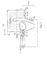
- Fig. 2 shows a portion of a furnace 1 fitted with a monitoring device 220.
- a control unit 230 with additional functionality as described below, replaces control unit 14 and is employed to control the fuel feed 5, the primary air feed 6 and the secondary air feed 7 to all of the burners 24 of furnace 1.
- Fig. 1 it includes a plurality of optical sources 221, which may be optical sources that pass through a portion of a flue duct, referred to as a sampling zone 18.
- the optical sources 221 provide optical beams 223 that pass through the flue gasses and the sampling zone 18 and are detected by a corresponding plurality of detectors 222. As the beams pass through the flue gasses, there is absorption of various wavelengths characteristic of the constituents within the flue gasses.
- the optical sources 221 are coupled to an electronics unit 225 to provide for characterization of received optical signals and identify the constituents, their concentrations and other physical aspects of substances in the flue gasses.
- the electronics unit 225 provides for estimations of physical aspects of the sampling zone 18 between the optical sources 221 and the corresponding detector 222.
- the present invention uses optical sources 221, and detectors 222 for measurement and assessment of gas species such as carbon monoxide (CO), carbon dioxide (CO 2 ), mercury (Hg), sulfur dioxide (SO 2 ), sulfur trioxide (SO 3 ), nitrogen dioxide (NO 2 ), nitrogen trioxide (NO 3 ) and oxygen (O 2 ) present in the sampling zone 18.
- gas species such as carbon monoxide (CO), carbon dioxide (CO 2 ), mercury (Hg), sulfur dioxide (SO 2 ), sulfur trioxide (SO 3 ), nitrogen dioxide (NO 2 ), nitrogen trioxide (NO 3 ) and oxygen (O 2 ) present in the sampling zone 18.
- SO 2 and SO 3 are collectively referred to as SOx.
- NO 2 and NO 3 are collectively referred to as NOx.
- optical source 221 and detector 222 and electronics unit 225 replace the function of the O 2 sensor 111 and control unit 14.
- optical source 221 and detector 222 and electronics unit 225 supplement the function of the O 2 sensor 111 and control unit 14.
- the monitoring device 220 provides for measuring the localized gas constituents and providing at least one of a monitored signal that may be fed backward to the furnace 1 to control combustion.
- the signals may also be fed forward to the emission control devices to provide advance notice of the constituents (pollutants) in the flue gas so that they may quickly 'ramp up' to remove the constituents.
- fuel and/or airflow from a fuel feed 5, primary air feed 6, and secondary air feed 7 can be modulated to give optimum furnace combustion and/or environmental performance.
- the overall combustion air provided to the system may be controlled by adjusting FD fan 16. Accordingly, use of the feedback signal and/or feed forward signal permits the system to adjust combustion and operation of emission control devices.
- the monitoring device 220 may be regarded as producing "measurement data,” “monitoring data,” “characterization data” and the like.
- Each of the feedback signal and the feed-forward signal as may be generated by the monitoring device 220 include forms of such data.
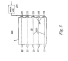
- Fig. 3 depicts a cross sectional view of a duct illustrating an embodiment of the combustion monitoring device 220 according to the present invention.
- optical sources 221 pass beams 223 through the sampling zone 18 to detectors 222. Constituents in the flue gasses absorb different wavelengths. Therefore, optical sources 221 must be selected to transmit within the absorption band of the constituents intended to be measured. Therefore, if O 2 is the constituent to be measured, there must be a laser 221 that transmits within the frequency band that covers the frequency band chacteristically absorbed by O 2 .
- the problem with prior art sensors is that they would only provide point measurements at specific locations. Many sensors would be required to provide an accurate overall reading. This would be costly and not feasible.
- the present invention samples along several beams 223 through the sampling zone. The readings sensed by the detectors 222 are averaged to provide a more accurate representation of an average concentration of a constituent over the sampling region 18.
- readings from a beam 223 passing through the center of the sampling region 18 may be weighted more than one that is on the periphery.
- the monitoring device 220 may be modified to detect SO 2 , SO 3 , mercury gas, NO 2 , NO 3 , CO 2 and other emissions, as commonly known in the art. These will be discussed with reference to Fig. 4 .
- the electronic unit 225 receives the signals from the detectors 222 and calculates the presence and amount of various entities. For example, electronics unit 225 may calculate the attenuation of characteristic frequencies to result in an absorption spectrum. This spectrum may match, for example, O 2 in the flue gas. The degree of optical absorption relative to the overall received signal will then indicate the concentration of O 2 , as well known in the art.
- an action may be determined. For example, if too much O 2 is detected in the flue gas, FD fan 16 of Fig. 2 may be slowed or the air diverted to reduce the amount of air and O 2 provided to the system.
- all optical sources 221 are parallel to each other and have the same distance between the optical sources 221 and their corresponding detectors 222.
- the optical sources 221 may optionally be placed at other orientations and have differing distances between them.
- the electronics unit 225 should have prestored information as to the distance between each laser 221 and its corresponding detector 222.
- the space between the source and detector indicates the amount of intervening constituents absorbing light. Therefore, if different laser 221, detector 222 have different distances between them, the readings should be adjusted accordingly.
- the estimations of concentrations and other physical properties may be performed using techniques as are known in the art.
- Exemplary techniques include evaluation of signal attenuation, signal absorption, fluorescence and other forms of wavelength shifting, scatter and other such techniques.
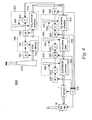
- Fig. 4 depicts a schematic block diagram of one embodiment of the present invention incorporated into a combustion system having several pollution control devices.
- the combustion device 1 burns fuel and creates flues gases that are passed downstream to emission control devices.
- emission control devices may be a selective catalytic reduction (SCR) system and/or a selective non-catalytic reduction (SNCR) system 300 providing a flow of ammonia and/or amines to reduce NO 2 , NO 3 in the flue gasses, a scrubber system 400 to remove SO 2 , SO 3 from the flue gasses, a mercury (Hg) control system 500 that uses activated carbon or additive to remove mercury gas species from the flue gas, and a particulate removal system 600 that removes particulate matter from the flue gas.
- an Electrostatic Precipitator (ESP) is used, however any type of particulate removal equipment may be used.
- a stack 810 regulates the flow of flue gas exiting the system.
- Monitor device 220, 320, 420, 520, 620, 720 may be constructed to monitor gas constituents such as O 2 , CO 2 , SO x , NO x , Hg, unburned fuel and particulate matter.
- Control systems 330, 430, 530 function in combination with other equipment to control the release of the monitored constituents.
- the appropriate downstream control unit 330, 430, 530, 630 should have advance notice to handle the large concentration of constituents. This allows the emission control systems time to prepare and react.
- monitoring devices 220, 320, 420, 520, 620 provide feed-forward signals to downstream elements.
- monitoring devices 220, 320, 420, 520, 620 and 720 also provide a feedback signal to upstream control devices 230, 330, 430, 530, 630 and 730 so that the emission control devices can examine how well they had controlled emissions of a constituent and adjust accordingly.
- upstream control devices 230, 330, 430, 530, 630 and 730 so that the emission control devices can examine how well they had controlled emissions of a constituent and adjust accordingly.
- Monitor devices 320, 420, 520, 620 and 720 can be constructed similar to monitor device 220 shown in Fig. 3 , to monitor different cross-sectional sampling zones 18 in the flue gas flow. Since monitor device 720 is measuring particulate matter in the flue gasses, it measures laser transmission through the flue gasses as opposed to looking at absorption spectra.
- Monitoring device 220 provides a feedback signal to control unit 230 to further adjust the FD fan 16 input and operating parameters of furnace 1, such as fuel flow, primary air flow and secondary air flow.
- monitor 220 monitors at least one of O 2 , CO, CO 2 , NO x , Hg, and unburned fuel and provides a signal indicating how to adjust the air input to the system from FD fan 16. It may also provide a signal to furnace 1 indicating how to adjust the primary airflow and secondary airflow. Usually this is done by adjusting air dampers and fuel flow valves.
- Monitor device 220 also monitors NOx levels and provides these levels in a feed forward signal to controller 330. These NOx levels provide an advance indication to controller 330 and injector 340 of the approximate amount of amines to inject into SCR/SNCR 310. Monitor device 220 may also send O 2 levels that may also provide an indication of what is to follow.
- Monitor device 320 monitors the NOx constituents downstream of an SCR/SNCR system 300 having a SCR/SNCR chamber 310.
- Monitor device 320 provides a feedback signal to a control unit 330 of the SCR/SNCR system 300 to indicate NOx levels downstream of SCR chamber 310.
- Controller 330 then re-adjusts the amount of material provided by a tank 340 based upon the input from monitoring device 320 and optionally, the input from monitoring device 220.
- Monitoring device 320 may also measure SO x emissions and provides a feed-forward signal to a control unit 430 of a scrubber system 400 indicating the amount of SO x that scrubber system 400 will be experiencing soon.
- monitoring device 420 will monitor the SO x levels in the flue gasses leaving a scrubber tank 410.
- the signal having the SOx levels is provided to control unit 430 to actuate a sprayer 440 to re-adjust an amount of limestone slurry, or a dry alkaline agent sprayed into scrubber tank 410 for reducing SOx emissions.
- Control unit 430 may also take into account the forward feed signal provided by monitoring device 320.
- control unit 530 of Hg removal system 500 may receive a feed forward signal from monitoring device 420 indicating upstream Hg levels and a feed back signal from monitor device 520 indicating downstream Hg levels. Control unit 530 calculates an adjustment to an injector 540 to adjust the amount of adsorbent introduced into Hg removal chamber 510 based upon the inputs received.
- Monitoring devices 520, 620 may also detect CO 2 levels upstream and downstream, respectively and provide signals indicating the detected levels to a control unit 630 of a CO 2 removal system 600.
- Control unit 630 then calculates the proper amount of material (chilled ammonia or other CO 2 removal material) to inject to remove the CO 2 from the flue gasses.
- Control unit 630 actuates an injector 640 of CO 2 removal system 600 to inject the proper amount of material.
- Monitor devices 620, 720 monitor the amounts of particulate material being released upstream and downstream of particulate removal system 700 and provides signals indicating these levels. These signals are provided to another control unit 730 of particulate removal system 700 that may provide adjustments to a particulate removal device such as an electrostatic precipitator (ESP) 710 shown in this embodiment. Optionally, it may restrict or reroute flue gasses through another particulate removal device (not shown) until enough of the particulate material has been removed, based upon input from monitor devices 620, 720.
- ESP electrostatic precipitator
- the feed forward signals were described as being from a constituent monitored immediately upstream from the device receiving the signal. It is to be understood that a feed forward signal from a constituent monitored in the flue gasses may be sent to one or more devices device located anywhere downstream. Similarly, a feedback signal from a constituent monitored in the flue gasses may be sent to one or more devices located anywhere upstream.
- the monitored signals are used by the pollution control devices to optimize the use of fuel, ammonia, amines, sorbent and/or other additives to reduce the release of pollutants. This can provide for substantial improvements in performance and/or operating costs of the furnace 1.
- the amount of NOx and mercury emitted are highly dependent upon the temperature of combustion. Therefore, by adjusting the amount of oxygen in the furnace 1 or by adjusting the temperature of furnace 1, the amounts of NOx and mercury can be adjusted.
- Monitoring devices 220, 320 measure the upstream and downstream NOx concentrations relative to the SCR/SNCR removal system 300.
- a signal indicating the upstream NOx concentration is provided by monitoring device 220 to control unit 230.
- a signal indicating the downstream NOx concentration is provided by monitoring device 320.
- monitoring devices 420, 520 measure the upstream and downstream mercury concentrations relative to the mercury removal system 500.
- a signal indicating the upstream mercury concentration is provided by monitoring device 420 to control unit 530.
- a signal indicating the downstream mercury concentration is provided by monitoring device 520.
- Control device 230 is adapted to calculate stoicheometry of fuel flow, primary air flow, and secondary air flow for various burners and burner levels to provide an optimum amount of oxygen used and an optimum combustion temperature to minimize both the NOx and the mercury emitted.
- features of merit in the invention include, without limitation: use of a grid of optical sources directly above the burner level to measure gas constituents from furnaces; an optical monitoring design for furnaces that can be used at each burner level or above each burner level that measures gas species to control the local burner stoichiometry; ability to control combustion within the furnace using laser grid measurement; primary control of boiler combustion using optical sources at the furnace outlet to control air feeds to the burners; an improved, non-grid design to measure gas constituents at the flue gas outlet; control of downstream emission control systems using laser grid measurements; use of NO x measurements in the furnace as a feed-forward signal to govern the flow feed rate of ammonia or amines to an SCR or a SNCR; as well as use of SO x and CO 2 measurements in the furnace as a monitored signal fed forward to govern feed rate of sorbent to a scrubber; laser measurements for the removal of mercury and laser control of acquisition of CO 2 constituents.
- the monitoring device 220 may be deployed as multiple monitoring systems. Further, the monitoring device 220 may be used anywhere in the stream of fuel, air, combustion and/or exhaust to achieve the desired level of control. Further, optical beams 123 may be generated which are described in two or three dimensions.
- the optical sources may be any lasers that transmit light in a band useful in detecting desired constituents in the flue gasses. This may include lasers of all types of gasses and species. Detection techniques may be based on modulation of signal frequency or signal wavelength as well as signal attenuation.
- embodiments of the monitoring device 220 include apparatus that measure gas concentrations by shining the laser beam through a sample of gas and measuring the amount of laser light absorbed.
- the optical source and detector wavelengths can be tuned to detect absorption at a variety of wavelengths. These properties give laser detectors a good combination of properties, including selectivity and sensitivity.
- a tunable laser generally emits light in the near infrared (NIR) region of the electromagnetic spectrum. Many of the combustion gases absorb light in NIR, and may be characterized by a number of individual "absorption lines.”
- NIR near infrared
- a tunable laser can be tuned to select a single absorption line of a target gas, which does not overlap with absorption lines from any other gases. Therefore, laser gas sensing can be considered selective with regard to sampling of gases.
- tunable lasers are relatively inexpensive. Accordingly, the monitoring device 220 is cost effective and easy to maintain.
- Exemplary tunable lasers are produced by Aegis Semiconductors, Inc. of Woburn, Massachusetts.
- One non-limiting example of a thermally tunable optical filter is disclosed in the U.S. Patent Application Publication No.: US/2005/0030628 A1 , entitled “Very Low Cost Narrow Band Infrared Sensor,” published February 10, 2005.
- This application provides an optical sensor for detecting a chemical in a sample region that includes an emitter for producing light, and for directing the light through the sample region.
- the sensor also includes a detector for receiving the light after the light passes through the sample region, and for producing a signal corresponding to the light, the detector receives.
- the sensor further includes a thermo-optic filter disposed between the emitter and the detector.
- the optical filter has a tunable passband for selectively filtering the light from the emitter.
- the passband of the optical filter is tunable by varying a temperature of the optical filter.
- the sensor also includes a controller for controlling the passband of the optical filter and for receiving the detection signal from the detector. The controller modulates the passband of the optical filter and analyzes the detection signal to determine whether an absorption peak of the chemical is present.
- the term "optical” makes reference to any wavelength of electromagnetic radiation useful for practice of the teachings herein.
- the electromagnetic radiation may include a wavelength, or band of wavelengths that are traditionally considered to be at least one of microwave, infrared, visible, ultraviolet, X-rays and gamma rays.
- the wavelength, or band of wavelengths selected for an optical signal are generally classified as at least one of infrared, visible, ultraviolet, or subcategories thereof.
- the laser 21 generally provides light amplification by stimulated emission of radiation. That is, a typical laser emits light in a narrow, low-divergence monochromatic beam with a well-defined wavelength. However, such as restriction is not necessary for practice of the teachings herein. In short, any optical beam that exhibits adequate properties for estimating measurement data may be used. Determinations of adequacy may be based upon a variety of factors, including perspective of the designer, user, owner and others. Accordingly, the laser 21 need not precisely exhibit lasing behavior, as traditionally defined.
- the present invention may be provided as part of a retrofit to existing combustion systems.
- the monitoring and control system 100 may be mounted onto existing components and integrated with existing controllers.
- a system making use of the teachings herein may also include computer software (i.e., machine readable instructions stored on machine readable media).
- the software may be used as a supplement to existing controller software (and/or firmware) or as an independent package.
- kit may be provided and include all other necessary components as may be needed for successful installation and operation.
- Example of other components include, without limitation, electrical wiring, power supplies, motor and/or manually operated valves, computer interfaces, user displays, assorted circuitry, assorted housings, relays, transformers, and other such components.
- a combustion system that includes at least one optical detector at the boiler outlet to measure the gas species, such as oxygen.
- the purpose of both systems in both locations is, among other things, to control the overall airflow to the boiler with the laser at the boiler outlet and to provide a local control of the boiler burners with the use of the optical sources mounted proximate to each burner.
- Software may be used in the functioning and operation of various parts of the present invention.
- electronics unit (102 of Figs. 1 , 2 ) and control unit of Figs. 1 , 3 may employ such software.
- This software may be provided in conjunction with a computer readable medium, may include any type of media, such as for example, magnetic storage, optical storage, magneto-optical storage, ROM, RAM, CD ROM, flash or any other computer readable medium, now known or unknown, that when executed cause a computer to implement the method and operate apparatus of the present invention.
- These instructions may provide for equipment operation, control, data collection and analysis and other functions deemed relevant by a user.
Landscapes
- Engineering & Computer Science (AREA)
- Mechanical Engineering (AREA)
- General Engineering & Computer Science (AREA)
- Chemical & Material Sciences (AREA)
- Combustion & Propulsion (AREA)
- Chemical Kinetics & Catalysis (AREA)
- General Chemical & Material Sciences (AREA)
- Investigating Or Analysing Materials By Optical Means (AREA)
- Regulation And Control Of Combustion (AREA)
- Treating Waste Gases (AREA)
- Incineration Of Waste (AREA)
Description
- This invention relates to coal-fired combustion systems, and more particularly to a flue gas monitoring system for accurate control of emissions of coal-fired combustion systems.
- In various coal-fired combustion systems, combustion is monitored by a measurement device located in the rear of the furnace. Typically, this is an oxygen sensor. This measurement device provides feedback signals that are used to control the combustion within the combustion system. Such a system is known, for example, from
EP 0 766 080 A . These sensors tend to be inaccurate since they only measure O2 at a specific sensor location. It would be more accurate to measure O2 at a number of locations. - Some systems, especially mechanical systems, take some time to react. In a standard system, a measurement device identifies properties of the flue gasses, and then reacts based upon the identified properties. If one of the properties measured is a high concentration of an emission gas, the appropriate pollution control system reacts to reduce the concentration of the gas before it leaves the combustion system. There is some lag time between when the gas being detected and when the gas concentration is actually reduced. It would be beneficial for systems, such as the emission control system, to receive an advance notice of the measured properties of the flue gas so that it may "ramp up" and reduce the system lag time.
- Thus, what are needed are methods and apparatus for accurate measurements of combustion conditions throughout a sampling zone associated with a boiler combustion system. Preferably, the measurements provide for improved control thus leading to improved efficiency.
- The invention may be embodied as an
efficient combustion system 1000 for monitoring a property of at least one constituent in flue gas from afurnace 1 which burns solid fuel, primary air and secondary air, the apparatus having anoptical monitoring device 220. - The
optical monitoring device 220 including a plurality ofoptical sources 221 for providingoptical beams 223 through the flue gasses in asampling zone 18. - A number of
detectors 222 each detect anoptical beam 223 and provide a sensed signal. - An
electronics unit 225 is coupled to thedetectors 222 and configured to combine the sensed signals from thedetectors 222 to estimate a property of at least one constituent in thesampling zone 18 and use the estimate to adjust the operation of thefurnace 1. - A
control unit 230 is coupled to theoptical monitoring device 220 and receives the combined signal. It controls the flow of thefuel feed 5,primary air feed 6 andsecondary air feed 7 to thefurnace 1 based upon the need indicated in the combined signal. - The invention may also be embodied as an
efficient combustion system 1000 having afurnace 1 for creating flue gasses having an upstreamoptical monitoring device 220 for sampling the flue gasses and for a concentration of a first constituent at its location and creating an upstream concentration signal. - It includes a downstream
optical monitoring device 320 for sampling the flue gasses and for the first constituent and creating a downstream concentration signal indicating the concentration of the first constituent in the flue gas at its location. - An
emission control system 300 capable of reducing the concentration of the first constituent in the flue gasses is located between, and coupled to themonitoring devices emission control system 300 receives flue gasses and the emission control device receives the upstream concentration signal and uses it to adjust its future operation on future flue gas concentrations to be received, and uses the downstream concentration signal to adjust its current operation. - The invention may further be embodied as an
efficient combustion system 1000 having afurnace 1 for creating flue gasses and a number of serially connected emission control systems. The emission control systems and the furnace are connected by ducts; - A
control unit 230 is coupled to the furnace and operates to control fuel flow, primary air and secondary air to thefurnace 1. - The system includes at least one
monitoring device 220 having a number ofoptical sources 221 with eachoptical source 221 passing an optical beam through the flue gasses to a correpondingdetector 222. Eachdetector 222 creates a number of sensed signals, the sensed signals are combined to provide a signal indicating the concentration of a constituent in the flue gasses. The monitoring system sends the combined signal to thecontrol unit 230 to controlfurnace 1 to minimize the concentration of the constituent emitted in the flue gasses. - Optionally, several monitoring devices are used to sample one or more constituents throughout the system. These may be used to as a feed forward signal to give advance notice of emission concentrations to downstream emission control devices, or provide feedback to upstream emission control devices.
- In addition, the feedback signals may be sent to a
controller 230 that controls the operation of thefurnace 1, and adjust oxygen concentration and/or combustion temperature to regulate NOx and mercury emissions. - The subject matter which is regarded as the invention is particularly pointed out and distinctly claimed in the claims at the conclusion of the specification. The foregoing and other features and advantages of the invention are apparent from the following detailed description taken in conjunction with the accompanying drawings in which:
-
Fig. 1 depicts a schematic diagram of a portion of a prior art combustion system; -
Fig. 2 depicts a schematic diagram of a portion of one embodiment of a combustion system according to the present invention; -
Fig. 3 depicts a cross sectional view of a duct illustrating an embodiment of a combustion monitoring system according to the present invention; and -
Fig. 4 depicts a schematic block diagram of one embodiment of the present invention incorporated into a combustion system having several emission control devices. - Disclosed is a method and apparatus for providing for accurate monitoring of combustion conditions, flue gas constituents from a combustion system, and controlling the combustion system and/or emission control devices based upon the monitoring. In various non-limiting embodiments provided herein, the combustion system is a solid fuel, gaseous or liquid fuel fired combustion system. The combustion system may be a combination furnace and boiler, or steam generator. One skilled in the art will recognize, however, that the embodiments provided are merely illustrative and are not limiting of the invention.
- The methods and apparatus make use of optical detection systems. As provided herein, the optical signaling and detection systems are simply referred to as a "monitoring system." In general, the monitoring system includes a variety of components for performing a variety of associated functions. The components may include a plurality of optical sources such as lasers, a plurality of sensors, a control unit, computer components, software (i.e., machine executable instructions stored on machine readable media), signaling devices, motor operated controls, at least one power supply and other such components. The monitoring system provides for a plurality of measurements of at least one gas constituent relative to a sampling zone. The plurality of measurements provide for, among other things, measurement of gas constituents in the sampling zone, such as in relation to a burner (i.e., a nozzle). The measurements may be performed in multiple locations by use of optical sensing technology, thus providing a localized, more responsive measure of fuel combustion. Of course, the monitoring system may also be viewed as a control system. More specifically, measurement data from the monitoring system may be used to control aspects of the combustion system and the emission control devices. Accordingly, for at least this reason, the monitoring system may be considered as a control system or at least as a part of a control system.
- Turning now to
Fig. 1 , there is shown a side elevational view of a portion aprior art furnace 1. The emission control devices are not shown here. A solid fuel, such as pulverized coal is entrained in a jet of primary air and provided to acombustion chamber 2 through acontrol unit 14. - A forced draft (FD)
fan 16 provides the primary air as well as secondary air also provided to controlunit 14 into asecondary air inlet 7. The air and fuel is combusted in acombustion chamber 2. Hot flue gasses are created and pass out of abackpass 3. - Throughout directions such as "downstream" means in the general direction of the flue gas flow. Similarly, the term "upstream" is opposite the direction of "downstream" going opposite the direction of flue gas flow.
- An oxygen (O2)
sensor 111 senses the oxygen concentration and passes the signal to adetector 112 to identify if the O2 is at the proper level. If not,detector 112 causes controlunit 14 to adjust fuel flow, primary airflow and secondary airflow. -
Fig. 2 shows a portion of afurnace 1 fitted with amonitoring device 220. Acontrol unit 230 with additional functionality as described below, replacescontrol unit 14 and is employed to control thefuel feed 5, theprimary air feed 6 and thesecondary air feed 7 to all of theburners 24 offurnace 1. - In addition to the parts described in connection with
Fig. 1 , it includes a plurality ofoptical sources 221, which may be optical sources that pass through a portion of a flue duct, referred to as asampling zone 18. - The
optical sources 221 provideoptical beams 223 that pass through the flue gasses and thesampling zone 18 and are detected by a corresponding plurality ofdetectors 222. As the beams pass through the flue gasses, there is absorption of various wavelengths characteristic of the constituents within the flue gasses. - The
optical sources 221 are coupled to anelectronics unit 225 to provide for characterization of received optical signals and identify the constituents, their concentrations and other physical aspects of substances in the flue gasses. Theelectronics unit 225 provides for estimations of physical aspects of thesampling zone 18 between theoptical sources 221 and thecorresponding detector 222. - The present invention uses
optical sources 221, anddetectors 222 for measurement and assessment of gas species such as carbon monoxide (CO), carbon dioxide (CO2), mercury (Hg), sulfur dioxide (SO2), sulfur trioxide (SO3), nitrogen dioxide (NO2), nitrogen trioxide (NO3) and oxygen (O2) present in thesampling zone 18. SO2 and SO3 are collectively referred to as SOx. Similarly, NO2 and NO3 are collectively referred to as NOx. - In one embodiment of the present invention,
optical source 221 anddetector 222 andelectronics unit 225 replace the function of the O2 sensor 111 andcontrol unit 14. - In an alternative embodiment on the present invention,
optical source 221 anddetector 222 andelectronics unit 225 supplement the function of the O2 sensor 111 andcontrol unit 14. - In various embodiments, the
monitoring device 220 provides for measuring the localized gas constituents and providing at least one of a monitored signal that may be fed backward to thefurnace 1 to control combustion. - The signals may also be fed forward to the emission control devices to provide advance notice of the constituents (pollutants) in the flue gas so that they may quickly 'ramp up' to remove the constituents.
- As a non-limiting example, depending on the situation, fuel and/or airflow from a
fuel feed 5,primary air feed 6, andsecondary air feed 7 can be modulated to give optimum furnace combustion and/or environmental performance. Also, the overall combustion air provided to the system may be controlled by adjustingFD fan 16. Accordingly, use of the feedback signal and/or feed forward signal permits the system to adjust combustion and operation of emission control devices. - For convenience of explanation, the
monitoring device 220 may be regarded as producing "measurement data," "monitoring data," "characterization data" and the like. Each of the feedback signal and the feed-forward signal as may be generated by themonitoring device 220 include forms of such data. -
Fig. 3 depicts a cross sectional view of a duct illustrating an embodiment of thecombustion monitoring device 220 according to the present invention. - As the flue gasses are passed through the backpass 3 (duct),
optical sources 221pass beams 223 through thesampling zone 18 todetectors 222. Constituents in the flue gasses absorb different wavelengths. Therefore,optical sources 221 must be selected to transmit within the absorption band of the constituents intended to be measured. Therefore, if O2 is the constituent to be measured, there must be alaser 221 that transmits within the frequency band that covers the frequency band chacteristically absorbed by O2. - The problem with prior art sensors is that they would only provide point measurements at specific locations. Many sensors would be required to provide an accurate overall reading. This would be costly and not feasible. The present invention samples along
several beams 223 through the sampling zone. The readings sensed by thedetectors 222 are averaged to provide a more accurate representation of an average concentration of a constituent over thesampling region 18. - Optionally, some readings may be weighted more than others. For example, readings from a
beam 223 passing through the center of thesampling region 18 may be weighted more than one that is on the periphery. - Similarly, the
monitoring device 220 may be modified to detect SO2, SO3, mercury gas, NO2, NO3, CO2 and other emissions, as commonly known in the art. These will be discussed with reference toFig. 4 . - The
electronic unit 225 receives the signals from thedetectors 222 and calculates the presence and amount of various entities. For example,electronics unit 225 may calculate the attenuation of characteristic frequencies to result in an absorption spectrum. This spectrum may match, for example, O2 in the flue gas. The degree of optical absorption relative to the overall received signal will then indicate the concentration of O2, as well known in the art. - Based upon the calculated amount of a given entity, or ratios of several entities, an action may be determined. For example, if too much O2 is detected in the flue gas,
FD fan 16 ofFig. 2 may be slowed or the air diverted to reduce the amount of air and O2 provided to the system. - In the embodiment shown, all
optical sources 221 are parallel to each other and have the same distance between theoptical sources 221 and theircorresponding detectors 222. - The
optical sources 221 may optionally be placed at other orientations and have differing distances between them. In such a case, theelectronics unit 225 should have prestored information as to the distance between eachlaser 221 and itscorresponding detector 222. The space between the source and detector indicates the amount of intervening constituents absorbing light. Therefore, ifdifferent laser 221,detector 222 have different distances between them, the readings should be adjusted accordingly. - The estimations of concentrations and other physical properties may be performed using techniques as are known in the art. Exemplary techniques include evaluation of signal attenuation, signal absorption, fluorescence and other forms of wavelength shifting, scatter and other such techniques.
-
Fig. 4 depicts a schematic block diagram of one embodiment of the present invention incorporated into a combustion system having several pollution control devices. - The
combustion device 1 burns fuel and creates flues gases that are passed downstream to emission control devices. These may be a selective catalytic reduction (SCR) system and/or a selective non-catalytic reduction (SNCR)system 300 providing a flow of ammonia and/or amines to reduce NO2, NO3 in the flue gasses, ascrubber system 400 to remove SO2, SO3 from the flue gasses, a mercury (Hg)control system 500 that uses activated carbon or additive to remove mercury gas species from the flue gas, and aparticulate removal system 600 that removes particulate matter from the flue gas. In this embodiment, an Electrostatic Precipitator (ESP) is used, however any type of particulate removal equipment may be used. Astack 810 regulates the flow of flue gas exiting the system. - The
first monitoring device 220 discussed above is placed just downstream fromfurnace 1.Monitor device Control systems - If there is an unusually large amount of any of these constituents created, the appropriate
downstream control unit - Therefore,
monitoring devices monitoring devices upstream control devices -
Monitor devices device 220 shown inFig. 3 , to monitor differentcross-sectional sampling zones 18 in the flue gas flow. Sincemonitor device 720 is measuring particulate matter in the flue gasses, it measures laser transmission through the flue gasses as opposed to looking at absorption spectra. -
Monitoring device 220 provides a feedback signal to controlunit 230 to further adjust theFD fan 16 input and operating parameters offurnace 1, such as fuel flow, primary air flow and secondary air flow. For example, monitor 220 monitors at least one of O2, CO, CO2, NOx, Hg, and unburned fuel and provides a signal indicating how to adjust the air input to the system fromFD fan 16. It may also provide a signal tofurnace 1 indicating how to adjust the primary airflow and secondary airflow. Usually this is done by adjusting air dampers and fuel flow valves. -
Monitor device 220 also monitors NOx levels and provides these levels in a feed forward signal tocontroller 330. These NOx levels provide an advance indication tocontroller 330 andinjector 340 of the approximate amount of amines to inject into SCR/SNCR 310.Monitor device 220 may also send O2 levels that may also provide an indication of what is to follow. -
Monitor device 320 monitors the NOx constituents downstream of an SCR/SNCR system 300 having a SCR/SNCR chamber 310.Monitor device 320 provides a feedback signal to acontrol unit 330 of the SCR/SNCR system 300 to indicate NOx levels downstream ofSCR chamber 310.Controller 330 then re-adjusts the amount of material provided by atank 340 based upon the input frommonitoring device 320 and optionally, the input frommonitoring device 220. -
Monitoring device 320 may also measure SOx emissions and provides a feed-forward signal to acontrol unit 430 of ascrubber system 400 indicating the amount of SOx thatscrubber system 400 will be experiencing soon. - Similarly,
monitoring device 420 will monitor the SOx levels in the flue gasses leaving ascrubber tank 410. The signal having the SOx levels is provided to controlunit 430 to actuate asprayer 440 to re-adjust an amount of limestone slurry, or a dry alkaline agent sprayed intoscrubber tank 410 for reducing SOx emissions. -
Control unit 430 may also take into account the forward feed signal provided bymonitoring device 320. - Similarly,
control unit 530 ofHg removal system 500 may receive a feed forward signal from monitoringdevice 420 indicating upstream Hg levels and a feed back signal frommonitor device 520 indicating downstream Hg levels.Control unit 530 calculates an adjustment to aninjector 540 to adjust the amount of adsorbent introduced intoHg removal chamber 510 based upon the inputs received. - Monitoring
devices control unit 630 of a CO2 removal system 600.Control unit 630 then calculates the proper amount of material (chilled ammonia or other CO2 removal material) to inject to remove the CO2 from the flue gasses.Control unit 630 actuates aninjector 640 of CO2 removal system 600 to inject the proper amount of material. -
Monitor devices particulate removal system 700 and provides signals indicating these levels. These signals are provided to anothercontrol unit 730 ofparticulate removal system 700 that may provide adjustments to a particulate removal device such as an electrostatic precipitator (ESP) 710 shown in this embodiment. Optionally, it may restrict or reroute flue gasses through another particulate removal device (not shown) until enough of the particulate material has been removed, based upon input frommonitor devices - The feed forward signals were described as being from a constituent monitored immediately upstream from the device receiving the signal. It is to be understood that a feed forward signal from a constituent monitored in the flue gasses may be sent to one or more devices device located anywhere downstream. Similarly, a feedback signal from a constituent monitored in the flue gasses may be sent to one or more devices located anywhere upstream.
- The monitored signals are used by the pollution control devices to optimize the use of fuel, ammonia, amines, sorbent and/or other additives to reduce the release of pollutants. This can provide for substantial improvements in performance and/or operating costs of the
furnace 1. - Many prior art systems have tried to optimize each of the pollution control devices independently. However, one or parameters may affect several type of emission. Therefore, optimizing several emission control devices simultaneously has a greater effect on the entire system than optimizing all emission control devices independently.
- It is known that the amount of NOx emissions are dependent upon the amount of oxygen present during combustion. The amount of oxygen present in combustion also has an effect on the amount of Hg emitted.
- Similarly, the amount of NOx and mercury emitted are highly dependent upon the temperature of combustion. Therefore, by adjusting the amount of oxygen in the
furnace 1 or by adjusting the temperature offurnace 1, the amounts of NOx and mercury can be adjusted. - Monitoring
devices SNCR removal system 300. A signal indicating the upstream NOx concentration is provided bymonitoring device 220 to controlunit 230. Similarly, a signal indicating the downstream NOx concentration is provided bymonitoring device 320. - Similarly,
monitoring devices mercury removal system 500. A signal indicating the upstream mercury concentration is provided bymonitoring device 420 to controlunit 530. Similarly, a signal indicating the downstream mercury concentration is provided bymonitoring device 520. -
Control device 230 is adapted to calculate stoicheometry of fuel flow, primary air flow, and secondary air flow for various burners and burner levels to provide an optimum amount of oxygen used and an optimum combustion temperature to minimize both the NOx and the mercury emitted. - Having thus described aspects of the present invention, one skilled in the art will recognize that features of merit in the invention include, without limitation: use of a grid of optical sources directly above the burner level to measure gas constituents from furnaces; an optical monitoring design for furnaces that can be used at each burner level or above each burner level that measures gas species to control the local burner stoichiometry; ability to control combustion within the furnace using laser grid measurement; primary control of boiler combustion using optical sources at the furnace outlet to control air feeds to the burners; an improved, non-grid design to measure gas constituents at the flue gas outlet; control of downstream emission control systems using laser grid measurements; use of NOx measurements in the furnace as a feed-forward signal to govern the flow feed rate of ammonia or amines to an SCR or a SNCR; as well as use of SOx and CO2 measurements in the furnace as a monitored signal fed forward to govern feed rate of sorbent to a scrubber; laser measurements for the removal of mercury and laser control of acquisition of CO2 constituents.
- It should be recognized that the
monitoring device 220 may be deployed as multiple monitoring systems. Further, themonitoring device 220 may be used anywhere in the stream of fuel, air, combustion and/or exhaust to achieve the desired level of control. Further, optical beams 123 may be generated which are described in two or three dimensions. - The optical sources may be any lasers that transmit light in a band useful in detecting desired constituents in the flue gasses. This may include lasers of all types of gasses and species. Detection techniques may be based on modulation of signal frequency or signal wavelength as well as signal attenuation. In general, embodiments of the
monitoring device 220 include apparatus that measure gas concentrations by shining the laser beam through a sample of gas and measuring the amount of laser light absorbed. However, the optical source and detector wavelengths can be tuned to detect absorption at a variety of wavelengths. These properties give laser detectors a good combination of properties, including selectivity and sensitivity. - Advantages of laser monitoring include an ability to characterize the gas constituents. That is, a tunable laser generally emits light in the near infrared (NIR) region of the electromagnetic spectrum. Many of the combustion gases absorb light in NIR, and may be characterized by a number of individual "absorption lines." A tunable laser can be tuned to select a single absorption line of a target gas, which does not overlap with absorption lines from any other gases. Therefore, laser gas sensing can be considered selective with regard to sampling of gases. A variety of other technical advantages is known to those skilled in the art. Further, tunable lasers are relatively inexpensive. Accordingly, the
monitoring device 220 is cost effective and easy to maintain. - Exemplary tunable lasers are produced by Aegis Semiconductors, Inc. of Woburn, Massachusetts. One non-limiting example of a thermally tunable optical filter is disclosed in the U.S. Patent Application Publication No.:
US/2005/0030628 A1 , entitled "Very Low Cost Narrow Band Infrared Sensor," published February 10, 2005. This application provides an optical sensor for detecting a chemical in a sample region that includes an emitter for producing light, and for directing the light through the sample region. The sensor also includes a detector for receiving the light after the light passes through the sample region, and for producing a signal corresponding to the light, the detector receives. The sensor further includes a thermo-optic filter disposed between the emitter and the detector. The optical filter has a tunable passband for selectively filtering the light from the emitter. The passband of the optical filter is tunable by varying a temperature of the optical filter. The sensor also includes a controller for controlling the passband of the optical filter and for receiving the detection signal from the detector. The controller modulates the passband of the optical filter and analyzes the detection signal to determine whether an absorption peak of the chemical is present. - One skilled in the art will recognize that the foregoing is merely one embodiment of the laser 121, and that a variety of other embodiments may be practiced. Accordingly, it should be recognized that the term "optical" makes reference to any wavelength of electromagnetic radiation useful for practice of the teachings herein. In general, the electromagnetic radiation may include a wavelength, or band of wavelengths that are traditionally considered to be at least one of microwave, infrared, visible, ultraviolet, X-rays and gamma rays. However, in practice, the wavelength, or band of wavelengths selected for an optical signal are generally classified as at least one of infrared, visible, ultraviolet, or subcategories thereof.
- Further, one should recognize that the laser 21 generally provides light amplification by stimulated emission of radiation. That is, a typical laser emits light in a narrow, low-divergence monochromatic beam with a well-defined wavelength. However, such as restriction is not necessary for practice of the teachings herein. In short, any optical beam that exhibits adequate properties for estimating measurement data may be used. Determinations of adequacy may be based upon a variety of factors, including perspective of the designer, user, owner and others. Accordingly, the laser 21 need not precisely exhibit lasing behavior, as traditionally defined.
- The present invention may be provided as part of a retrofit to existing combustion systems. For example, the monitoring and
control system 100 may be mounted onto existing components and integrated with existing controllers. Accordingly, a system making use of the teachings herein may also include computer software (i.e., machine readable instructions stored on machine readable media). The software may be used as a supplement to existing controller software (and/or firmware) or as an independent package. - Further, a kit may be provided and include all other necessary components as may be needed for successful installation and operation. Example of other components include, without limitation, electrical wiring, power supplies, motor and/or manually operated valves, computer interfaces, user displays, assorted circuitry, assorted housings, relays, transformers, and other such components.
- Accordingly, provided is a combustion system that includes at least one optical detector at the boiler outlet to measure the gas species, such as oxygen. The purpose of both systems in both locations is, among other things, to control the overall airflow to the boiler with the laser at the boiler outlet and to provide a local control of the boiler burners with the use of the optical sources mounted proximate to each burner.
- Software may be used in the functioning and operation of various parts of the present invention. For example, electronics unit (102 of
Figs. 1 ,2 ) and control unit ofFigs. 1 ,3 may employ such software. This software may be provided in conjunction with a computer readable medium, may include any type of media, such as for example, magnetic storage, optical storage, magneto-optical storage, ROM, RAM, CD ROM, flash or any other computer readable medium, now known or unknown, that when executed cause a computer to implement the method and operate apparatus of the present invention. These instructions may provide for equipment operation, control, data collection and analysis and other functions deemed relevant by a user. - While the invention has been described with reference to exemplary embodiments, it will be understood by those skilled in the art that various changes may be made and equivalents may be substituted for elements thereof without departing from the scope of the invention. In addition, many modifications may be made to adapt a particular situation or material to the teachings of the invention without departing from the essential scope thereof. Therefore, it is intended that the invention not be limited to the particular embodiment disclosed as the best mode contemplated for carrying out this invention, but that the invention will include all embodiments falling within the scope of the appended claims.
Claims (11)
- An efficient combustion and gas control system (1000) for monitoring a concentration of at least one constituent in flue gas from a furnace (1) that burns solid fuel, primary air and secondary air, the combustion and gas control system comprising:at least one optical monitoring device comprising:a plurality of optical sources (221) for providing optical beams (223) through the flue gasses in a sampling zone (18), anda plurality of detectors (222), each for detecting an optical beam (223) and for providing a sensed signal,an electronics unit (225) coupled to the detectors (222) configured to combine the sensed signals from the detectors (222) to provide a combined signal indicating a concentration of the at least one constituent in the sampling zone (18); anda plurality of emission control systems (300, 400, 500, 600, 700) located downstream from, and coupled to the at least one optical monitoring device (220, 320, 420, 520, 620, 720), adapted to receive at least one combined signal from the optical monitoring device (220, 320, 420, 520, 620, 720) indicating the concentration of the at least one constituent, characterised in that the at least one optical monitoring device is a downstream optical monitoring device positioned downstream of the furnace (220, 320, 420, 520, 620, 720) and the plurality of emission control systems uses the at least one combined signal from the downstream optical monitoring device and prepares it for future operation on a first of the constituents.
- The efficient combustion and gas control system (1000) as in claim 1, wherein the at least one optical source (221) comprises a laser.
- The efficient combustion and gas control system (1000) as in claim 1, wherein the at least one constituent is selected from the group consisting of:sulfur dioxide (SO2), sulfur trioxide (SO3), nitrogen dioxide (NO2), nitrogen trioxide (NO3), mercury (Hg) and carbon dioxide (CO2), mercury (Hg) and suspended particulates.
- The efficient combustion and gas control system (1000) as in claim 1, wherein the at least one emission control system (300, 400, 500, 600, 700) is selected from the group consisting of:a selective catalytic reduction (SCR) system (300), a selective non-catalytic reduction (SNCR) system (300), a scrubber system (400), a mercury control system (500), a CO2 removal system (600), and a particulate removal system (700); andat least one additional optical monitoring device (220, 320, 420, 520, 620, 720) for creating a second combined signal indicating a concentration of another constituent in flue gas and using the second combined signal to adjust the furnace (1) operation.
- The efficient combustion and gas control system (1000) of claim 1, wherein at least one of the beams (223) is not horizontal as it passes through the sampling zone (18).
- The efficient combustion and gas control system (1000) of claim 1, comprising:an upstream optical monitoring device (220, 320, 420, 520, 620) positioned upstream of the at least one downstream optical monitoring device (320, 420, 520, 620, 720) the upstream optical monitoring device (220, 320, 420, 520, 620) being operable to sample the flue gases, measure an amount of at least the first constituent in the sampled flue gases at a first location and create an upstream concentration signal from the measured amount at the first location;the downstream optical monitoring device (320, 420, 520, 620, 720) adapted to sample the flue gases, measure an amount of at least the first constituent at a second location downstream with respect to the first location, and create a downstream concentration signal from the measured amount at the second location;the at least one emission control system (300, 400, 500, 600, 700) located between, and coupled to the upstream and downstream optical monitoring devices, the emission control system (300, 400, 500, 600, 700) capable of receiving flue gases and reducing the amount of the first constituent in the flue gasses, the emission control system (300) receiving the upstream concentration signal and using it to prepare for its future operation on future flue gas concentrations to be received, and using the downstream concentration signal to adjust its current operation.
- The efficient combustion and gas control system (1000) of claim 6, wherein:the at least one upstream optical monitoring device (220, 320, 420, 520, 620) is operable to create a second upstream concentration signal indicating the concentration of a second constituent in the flue gas at its location;the at least one downstream optical monitoring device (320, 420, 520, 620, 720) is operable to create a second downstream concentration signal indicating the concentration of the second constituent in the flue gas at its location; andthe at least one emission control system (300, 400, 500, 600, 700) is operable to reduce the concentration of the second constituent in the flue gasses and to receive; the second upstream concentration signal and using it to adjust its future operation on future flue gas concentrations of the second constituent to be received, and using the downstream concentration signal to adjust its current operation.
- The efficient combustion and gas control system (1000) of claim 6, wherein the first constituent is selected from the group consisting of:sulfur dioxide (SO2), sulfur trioxide (SO3), nitrogen dioxide (NO2), nitrogen trioxide (NO3), mercury (Hg) and carbon dioxide (CO2) mercury (Hg) and suspended particulates.
- The efficient combustion and gas control system (1000) of claim 7, wherein the second constituent is selected from the group consisting of:sulfur dioxide (SO2), sulfur trioxide (SO3), nitrogen dioxide (NO2), nitrogen trioxide (NO3), mercury (Hg) and carbon dioxide (CO2) mercury (Hg) and suspended particulates.
- The efficient combustion and gas control system (1000) of claim 6, wherein the emission control system is selected from the group consisting of:NOx removal system (300), SOx removal system (400), mercury removal system (500), CO2 removal system (600) and particulate removal system (700).
- The efficient combustion and gas control system (1000) of claim 7, wherein the second emission control system is selected from the group consisting of:NOx removal system (300), SOx removal system (400), mercury removal system (500), CO2 removal system (600) and particulate removal system (700).
Priority Applications (1)
| Application Number | Priority Date | Filing Date | Title |
|---|---|---|---|
| PL10742057T PL2467641T3 (en) | 2009-08-21 | 2010-07-21 | Optical flue gas monitor and control |
Applications Claiming Priority (2)
| Application Number | Priority Date | Filing Date | Title |
|---|---|---|---|
| US12/545,134 US20110045422A1 (en) | 2009-08-21 | 2009-08-21 | Optical flue gas monitor and control |
| PCT/US2010/042711 WO2011022158A1 (en) | 2009-08-21 | 2010-07-21 | Optical flue gas monitor and control |
Publications (2)
| Publication Number | Publication Date |
|---|---|
| EP2467641A1 EP2467641A1 (en) | 2012-06-27 |
| EP2467641B1 true EP2467641B1 (en) | 2014-11-26 |
Family
ID=43242963
Family Applications (1)
| Application Number | Title | Priority Date | Filing Date |
|---|---|---|---|
| EP10742057.2A Not-in-force EP2467641B1 (en) | 2009-08-21 | 2010-07-21 | Optical flue gas monitor and control |
Country Status (9)
| Country | Link |
|---|---|
| US (1) | US20110045422A1 (en) |
| EP (1) | EP2467641B1 (en) |
| KR (1) | KR101353987B1 (en) |
| CN (1) | CN102625891B (en) |
| CA (1) | CA2771509C (en) |
| IN (1) | IN2012DN02377A (en) |
| PL (1) | PL2467641T3 (en) |
| TW (1) | TWI467119B (en) |
| WO (1) | WO2011022158A1 (en) |
Cited By (1)
| Publication number | Priority date | Publication date | Assignee | Title |
|---|---|---|---|---|
| CN107166359A (en) * | 2016-03-07 | 2017-09-15 | 通用电器技术有限公司 | For the system and method for the condensation for adjusting the flue gas in steam generator |
Families Citing this family (32)
| Publication number | Priority date | Publication date | Assignee | Title |
|---|---|---|---|---|
| US20090214993A1 (en) * | 2008-02-25 | 2009-08-27 | Fuller Timothy A | System using over fire zone sensors and data analysis |
| WO2010096135A1 (en) * | 2009-02-18 | 2010-08-26 | W R Systems, Ltd. | Emissions monitoring apparatus, system, and method |
| CN102207289B (en) * | 2011-05-23 | 2012-09-05 | 河南电力试验研究院 | Device and method for regulating flue gas ingredients of side wall water cooling wall of front-rear wall hedging combustion boiler automatically |
| US9464512B2 (en) | 2011-08-05 | 2016-10-11 | Halliburton Energy Services, Inc. | Methods for fluid monitoring in a subterranean formation using one or more integrated computational elements |
| US8900354B2 (en) * | 2011-09-08 | 2014-12-02 | The Power Industrial Group Ltd. | Boosted no-lance injection systems and methods |
| US20130087709A1 (en) * | 2011-10-07 | 2013-04-11 | Heidy Hodex Visbal Mendoza | Mercury gas sensing using terahertz time-domain spectroscopy |
| CN103814287A (en) * | 2011-10-07 | 2014-05-21 | 英派尔科技开发有限公司 | Mercury gas sensing method using terahertz time-domain spectroscopy |
| CN102590097B (en) * | 2012-03-05 | 2013-09-25 | 哈尔滨工业大学 | Mercury vapor continuous monitoring method based on diode laser |
| US9802154B2 (en) | 2012-03-30 | 2017-10-31 | Fuel Tech, Inc. | Process for sulfur dioxide, hydrochloric acid and mercury mediation |
| KR101351134B1 (en) * | 2012-09-27 | 2014-01-15 | 한국전력공사 | System for evaluating of carbon dioxide absorbent |
| MX2015011065A (en) * | 2013-02-27 | 2016-02-11 | Fuel Tech Inc | Processes, apparatus, compositions and systems for reducing emissions of hci and/or sulfur oxides. |
| US9289721B2 (en) | 2013-02-27 | 2016-03-22 | Fuel Tech, Inc. | Process and apparatus for improving the operation of wet scrubbers |
| US9399597B2 (en) | 2013-04-01 | 2016-07-26 | Fuel Tech, Inc. | Ash compositions recovered from coal combustion gases having reduced emissions of HCI and/or mercury |
| US9718025B2 (en) | 2013-04-01 | 2017-08-01 | Fuel Tech, Inc. | Reducing hydrochloric acid in cement kilns |
| DE102013014576A1 (en) * | 2013-09-02 | 2015-03-05 | Mertik Maxitrol Gmbh & Co. Kg | Device for controlling the combustion air supply |
| US20150226421A1 (en) * | 2014-02-12 | 2015-08-13 | Breen Energy Solutions | Method of Co-Firing Coal or Oil with a Gaseous Fuel in a Furnace |
| GB2524836A (en) | 2014-04-04 | 2015-10-07 | Servomex Group Ltd | Attachment and alignment device for optical sources, detectors and analysers, and modular analysis system |
| EP2962743A1 (en) | 2014-07-04 | 2016-01-06 | Alstom Technology Ltd | A boiler and a method for NOx emission control from a boiler with SNCR |
| CN104180392B (en) * | 2014-08-27 | 2017-05-03 | 中国科学技术大学 | Full-automatic combustion control device for boilers |
| DE102015204883A1 (en) * | 2015-03-18 | 2016-09-22 | Siemens Aktiengesellschaft | Laser-based IR spectroscopy for the measurement of sulfur trioxide in the exhaust gas of gas power plants |
| JP6537987B2 (en) * | 2016-02-01 | 2019-07-03 | 住友重機械工業株式会社 | Combustion control system and combustion control method |
| KR101738091B1 (en) * | 2016-08-02 | 2017-05-19 | 대림로얄이앤피(주) | CONTROLLING SYSTEM OF AIR FUEL RATION AND NOx |
| JP6599307B2 (en) * | 2016-12-28 | 2019-10-30 | 三菱日立パワーシステムズ株式会社 | Combustion device and boiler equipped with the same |
| CN106769899A (en) * | 2016-12-30 | 2017-05-31 | 武汉六九传感科技有限公司 | A kind of NH3 laser analysis module |
| US11619384B2 (en) | 2017-04-24 | 2023-04-04 | General Electric Technology Gmbh | System and method for operating a combustion chamber |
| KR102025146B1 (en) * | 2018-03-08 | 2019-09-25 | 두산중공업 주식회사 | System for monitoring a state of catalytic reaction in power plant DeNOx facilities, and method thereof |
| US11966669B2 (en) | 2018-05-14 | 2024-04-23 | Jfe Steel Corporation | Molten metal component estimation device, method of estimating molten metal component, and method of manufacturing molten metal |
| US11921036B2 (en) * | 2018-09-21 | 2024-03-05 | Tenova Goodfellow Inc. | In situ apparatus for furnace off-gas constituent and flow velocity measurement |
| CN111307675B (en) * | 2019-11-22 | 2022-07-12 | 南京理工大学 | Fine particulate matter concentration monitoring method based on millimeter wave radiometer |
| US20210381688A1 (en) * | 2020-06-06 | 2021-12-09 | Howden Alphair Ventilating Systems, Inc. | Low emission direct fired process air heating |
| CN114324095B (en) * | 2021-12-30 | 2023-10-24 | 中国石油大学(北京) | Monitoring device for particle impurity concentration in gas pipeline |
| US20240302040A1 (en) * | 2023-03-10 | 2024-09-12 | Stmicroelectronics S.R.I. | Sensor device and method for flame presence detection |
Family Cites Families (27)
| Publication number | Priority date | Publication date | Assignee | Title |
|---|---|---|---|---|
| US4368031A (en) * | 1980-07-14 | 1983-01-11 | Combustion Engineering, Inc. | Stationary flame scanner for tilting burner |
| US4657872A (en) * | 1984-11-13 | 1987-04-14 | Cornell Research Foundation, Inc. | Laser-enhanced flame ionization detection |
| US4639717A (en) * | 1985-07-15 | 1987-01-27 | Electronics Corporation Of America | Method and apparatus for monitoring flame condition |
| JPS63217130A (en) * | 1987-03-03 | 1988-09-09 | Ishikawajima Harima Heavy Ind Co Ltd | Automatic combustion regulator |
| US5020454A (en) * | 1990-10-31 | 1991-06-04 | Combustion Engineering, Inc. | Clustered concentric tangential firing system |
| US5252060A (en) * | 1992-03-27 | 1993-10-12 | Mckinnon J Thomas | Infrared laser fault detection method for hazardous waste incineration |
| US5575984A (en) * | 1994-06-09 | 1996-11-19 | Abb Environmental Systems, Div. Of Abb Flakt, Inc. | Method for preparing calcium carbonate for scrubbing sulfur oxides from combustion effluents |
| EP0766042A1 (en) * | 1995-09-29 | 1997-04-02 | FINMECCANICA S.p.A. AZIENDA ANSALDO | System for automatically controlling the supply of a basic substance to a combustion chamber |
| EP0766080A1 (en) * | 1995-09-29 | 1997-04-02 | FINMECCANICA S.p.A. AZIENDA ANSALDO | System and method for monitoring combustion and pollutants by means of laser diodes |
| EP0829684A1 (en) * | 1996-09-13 | 1998-03-18 | FINMECCANICA S.p.A. AZIENDA ANSALDO | Method and device for the selective, non catalytic reduction of the emissions from boiler plants |
| US20020179493A1 (en) * | 1999-08-20 | 2002-12-05 | Environmental & Energy Enterprises, Llc | Production and use of a premium fuel grade petroleum coke |
| US6468069B2 (en) * | 1999-10-25 | 2002-10-22 | Jerome H. Lemelson | Automatically optimized combustion control |
| US6775645B2 (en) * | 2001-11-14 | 2004-08-10 | Electric Power Research Institute, Inc. | Application of symbol sequence analysis and temporal irreversibility to monitoring and controlling boiler flames |
| US7326340B2 (en) * | 2003-03-05 | 2008-02-05 | Siemens Water Technologies Holding Corp. | System for controlling sulfide generation |
| AU2004227359B2 (en) * | 2003-03-31 | 2009-07-30 | Zolo Technologies, Inc. | Method and apparatus for the monitoring and control of combustion |
| US20050030628A1 (en) | 2003-06-20 | 2005-02-10 | Aegis Semiconductor | Very low cost narrow band infrared sensor |
| US7536232B2 (en) * | 2004-08-27 | 2009-05-19 | Alstom Technology Ltd | Model predictive control of air pollution control processes |
| US7514053B2 (en) * | 2005-04-21 | 2009-04-07 | Envirosolv Energy Llc | Method for removing sulfur dioxide, mercury, and nitrogen oxides from a gas stream |
| WO2007062257A2 (en) * | 2005-11-28 | 2007-05-31 | Lew Holdings, Lls | Trajectory gasifier burners |
| JP5013808B2 (en) * | 2006-10-13 | 2012-08-29 | 三菱重工環境・化学エンジニアリング株式会社 | Combustion control device for stoker-type incinerator |
| US7553463B2 (en) * | 2007-01-05 | 2009-06-30 | Bert Zauderer | Technical and economic optimization of combustion, nitrogen oxides, sulfur dioxide, mercury, carbon dioxide, coal ash and slag and coal slurry use in coal fired furnaces/boilers |
| US8375872B2 (en) * | 2007-02-23 | 2013-02-19 | Intertek APTECH | Process for reduction of sulfur compounds and nitrogen compounds in the exhaust gases of combustion devices |
| JP5336394B2 (en) * | 2007-02-26 | 2013-11-06 | ヨコガワ・コーポレーション・オブ・アメリカ | Combustion gas analysis |
| US8409534B2 (en) * | 2007-03-28 | 2013-04-02 | The United States Of America As Represented By The Administrator Of The National Aeronautics And Space Administration | Control of emissions |
| US7655202B2 (en) * | 2007-10-09 | 2010-02-02 | Ceramatec, Inc. | Coal fired flue gas treatment and process |
| US8256267B2 (en) * | 2008-08-14 | 2012-09-04 | Breen Energy Solutions | Method and apparatus for detection, measurement and control of sulfur-trioxide and other condensables in flue gas |
| US8181451B2 (en) * | 2008-11-20 | 2012-05-22 | Alstom Technology Ltd | Method of controlling the operation of a selective catalytic reduction plant |
-
2009
- 2009-08-21 US US12/545,134 patent/US20110045422A1/en not_active Abandoned
-
2010
- 2010-07-21 EP EP10742057.2A patent/EP2467641B1/en not_active Not-in-force
- 2010-07-21 CA CA2771509A patent/CA2771509C/en not_active Expired - Fee Related
- 2010-07-21 WO PCT/US2010/042711 patent/WO2011022158A1/en active Application Filing
- 2010-07-21 PL PL10742057T patent/PL2467641T3/en unknown
- 2010-07-21 KR KR1020127007024A patent/KR101353987B1/en not_active IP Right Cessation
- 2010-07-21 CN CN201080047981.5A patent/CN102625891B/en not_active Expired - Fee Related
- 2010-08-20 TW TW99128014A patent/TWI467119B/en not_active IP Right Cessation
-
2012
- 2012-03-20 IN IN2377DEN2012 patent/IN2012DN02377A/en unknown
Cited By (1)
| Publication number | Priority date | Publication date | Assignee | Title |
|---|---|---|---|---|
| CN107166359A (en) * | 2016-03-07 | 2017-09-15 | 通用电器技术有限公司 | For the system and method for the condensation for adjusting the flue gas in steam generator |
Also Published As
| Publication number | Publication date |
|---|---|
| CN102625891B (en) | 2015-04-01 |
| CA2771509A1 (en) | 2011-02-24 |
| US20110045422A1 (en) | 2011-02-24 |
| WO2011022158A1 (en) | 2011-02-24 |
| IN2012DN02377A (en) | 2015-08-21 |
| CN102625891A (en) | 2012-08-01 |
| KR101353987B1 (en) | 2014-01-22 |
| PL2467641T3 (en) | 2015-04-30 |
| TW201129763A (en) | 2011-09-01 |
| EP2467641A1 (en) | 2012-06-27 |
| KR20120057632A (en) | 2012-06-05 |
| TWI467119B (en) | 2015-01-01 |
| CA2771509C (en) | 2015-11-24 |
Similar Documents
| Publication | Publication Date | Title |
|---|---|---|
| EP2467641B1 (en) | Optical flue gas monitor and control | |
| US20110045420A1 (en) | Burner monitor and control | |
| CA2764010C (en) | Gas detector apparatus | |
| US9677762B2 (en) | Automated flare control | |
| JP2010520997A (en) | Method and system for detecting particles | |
| JP5453607B2 (en) | Light scattering dust concentration meter | |
| WO2010102375A1 (en) | Apparatus for continuous in situ monitoring of elemental mercury vapour, and method of using same | |
| KR101760259B1 (en) | Extractive continuous ammonia monitoring system | |
| CN101128698A (en) | Method for increasing the package throughput in rotary kiln plants | |
| JP5976885B1 (en) | Light scattering dust densitometer capable of measuring even low-flow exhaust gas and dust concentration measuring method | |
| US10067052B2 (en) | Apparatus for optical in-situ gas analysis | |
| CN113692514A (en) | Incineration system provided with grate type incinerator | |
| JP2016075519A (en) | Concentration evaluating device and method, powder supplying system and method, and pulverized coal boiler | |
| JP2019178847A (en) | Waste moisture percentage measuring apparatus, stoker-type waste incinerator, waste moisture percentage measuring method, and waste incineration method | |
| KR20060006410A (en) | Light-extinction type diesel smoke meter | |
| JPH01272940A (en) | Powder supply amount controller | |
| JP2005200834A (en) | Ventilation controller for road tunnel |
Legal Events
| Date | Code | Title | Description |
|---|---|---|---|
| PUAI | Public reference made under article 153(3) epc to a published international application that has entered the european phase |
Free format text: ORIGINAL CODE: 0009012 |
|
| 17P | Request for examination filed |
Effective date: 20120315 |
|
| AK | Designated contracting states |
Kind code of ref document: A1 Designated state(s): AL AT BE BG CH CY CZ DE DK EE ES FI FR GB GR HR HU IE IS IT LI LT LU LV MC MK MT NL NO PL PT RO SE SI SK SM TR |
|
| DAX | Request for extension of the european patent (deleted) | ||
| GRAP | Despatch of communication of intention to grant a patent |
Free format text: ORIGINAL CODE: EPIDOSNIGR1 |
|
| INTG | Intention to grant announced |
Effective date: 20131203 |
|
| GRAS | Grant fee paid |
Free format text: ORIGINAL CODE: EPIDOSNIGR3 |
|
| GRAA | (expected) grant |
Free format text: ORIGINAL CODE: 0009210 |
|
| AK | Designated contracting states |
Kind code of ref document: B1 Designated state(s): AL AT BE BG CH CY CZ DE DK EE ES FI FR GB GR HR HU IE IS IT LI LT LU LV MC MK MT NL NO PL PT RO SE SI SK SM TR |
|
| REG | Reference to a national code |
Ref country code: GB Ref legal event code: FG4D |
|
| REG | Reference to a national code |
Ref country code: CH Ref legal event code: EP |
|
| REG | Reference to a national code |
Ref country code: AT Ref legal event code: REF Ref document number: 698422 Country of ref document: AT Kind code of ref document: T Effective date: 20141215 |
|
| REG | Reference to a national code |
Ref country code: IE Ref legal event code: FG4D |
|
| REG | Reference to a national code |
Ref country code: DE Ref legal event code: R096 Ref document number: 602010020545 Country of ref document: DE Effective date: 20141231 |
|
| REG | Reference to a national code |
Ref country code: NL Ref legal event code: VDEP Effective date: 20141126 |
|
| REG | Reference to a national code |
Ref country code: AT Ref legal event code: MK05 Ref document number: 698422 Country of ref document: AT Kind code of ref document: T Effective date: 20141126 |
|
| REG | Reference to a national code |
Ref country code: LT Ref legal event code: MG4D |
|
| PG25 | Lapsed in a contracting state [announced via postgrant information from national office to epo] |
Ref country code: NL Free format text: LAPSE BECAUSE OF FAILURE TO SUBMIT A TRANSLATION OF THE DESCRIPTION OR TO PAY THE FEE WITHIN THE PRESCRIBED TIME-LIMIT Effective date: 20141126 Ref country code: PT Free format text: LAPSE BECAUSE OF FAILURE TO SUBMIT A TRANSLATION OF THE DESCRIPTION OR TO PAY THE FEE WITHIN THE PRESCRIBED TIME-LIMIT Effective date: 20150326 Ref country code: FI Free format text: LAPSE BECAUSE OF FAILURE TO SUBMIT A TRANSLATION OF THE DESCRIPTION OR TO PAY THE FEE WITHIN THE PRESCRIBED TIME-LIMIT Effective date: 20141126 Ref country code: ES Free format text: LAPSE BECAUSE OF FAILURE TO SUBMIT A TRANSLATION OF THE DESCRIPTION OR TO PAY THE FEE WITHIN THE PRESCRIBED TIME-LIMIT Effective date: 20141126 Ref country code: NO Free format text: LAPSE BECAUSE OF FAILURE TO SUBMIT A TRANSLATION OF THE DESCRIPTION OR TO PAY THE FEE WITHIN THE PRESCRIBED TIME-LIMIT Effective date: 20150226 Ref country code: IS Free format text: LAPSE BECAUSE OF FAILURE TO SUBMIT A TRANSLATION OF THE DESCRIPTION OR TO PAY THE FEE WITHIN THE PRESCRIBED TIME-LIMIT Effective date: 20150326 Ref country code: LT Free format text: LAPSE BECAUSE OF FAILURE TO SUBMIT A TRANSLATION OF THE DESCRIPTION OR TO PAY THE FEE WITHIN THE PRESCRIBED TIME-LIMIT Effective date: 20141126 |
|
| REG | Reference to a national code |
Ref country code: PL Ref legal event code: T3 |
|
| PG25 | Lapsed in a contracting state [announced via postgrant information from national office to epo] |
Ref country code: LV Free format text: LAPSE BECAUSE OF FAILURE TO SUBMIT A TRANSLATION OF THE DESCRIPTION OR TO PAY THE FEE WITHIN THE PRESCRIBED TIME-LIMIT Effective date: 20141126 Ref country code: SE Free format text: LAPSE BECAUSE OF FAILURE TO SUBMIT A TRANSLATION OF THE DESCRIPTION OR TO PAY THE FEE WITHIN THE PRESCRIBED TIME-LIMIT Effective date: 20141126 Ref country code: AT Free format text: LAPSE BECAUSE OF FAILURE TO SUBMIT A TRANSLATION OF THE DESCRIPTION OR TO PAY THE FEE WITHIN THE PRESCRIBED TIME-LIMIT Effective date: 20141126 Ref country code: HR Free format text: LAPSE BECAUSE OF FAILURE TO SUBMIT A TRANSLATION OF THE DESCRIPTION OR TO PAY THE FEE WITHIN THE PRESCRIBED TIME-LIMIT Effective date: 20141126 Ref country code: CY Free format text: LAPSE BECAUSE OF FAILURE TO SUBMIT A TRANSLATION OF THE DESCRIPTION OR TO PAY THE FEE WITHIN THE PRESCRIBED TIME-LIMIT Effective date: 20141126 Ref country code: GR Free format text: LAPSE BECAUSE OF FAILURE TO SUBMIT A TRANSLATION OF THE DESCRIPTION OR TO PAY THE FEE WITHIN THE PRESCRIBED TIME-LIMIT Effective date: 20150227 |
|
| PG25 | Lapsed in a contracting state [announced via postgrant information from national office to epo] |
Ref country code: EE Free format text: LAPSE BECAUSE OF FAILURE TO SUBMIT A TRANSLATION OF THE DESCRIPTION OR TO PAY THE FEE WITHIN THE PRESCRIBED TIME-LIMIT Effective date: 20141126 Ref country code: DK Free format text: LAPSE BECAUSE OF FAILURE TO SUBMIT A TRANSLATION OF THE DESCRIPTION OR TO PAY THE FEE WITHIN THE PRESCRIBED TIME-LIMIT Effective date: 20141126 Ref country code: CZ Free format text: LAPSE BECAUSE OF FAILURE TO SUBMIT A TRANSLATION OF THE DESCRIPTION OR TO PAY THE FEE WITHIN THE PRESCRIBED TIME-LIMIT Effective date: 20141126 Ref country code: SK Free format text: LAPSE BECAUSE OF FAILURE TO SUBMIT A TRANSLATION OF THE DESCRIPTION OR TO PAY THE FEE WITHIN THE PRESCRIBED TIME-LIMIT Effective date: 20141126 Ref country code: RO Free format text: LAPSE BECAUSE OF FAILURE TO SUBMIT A TRANSLATION OF THE DESCRIPTION OR TO PAY THE FEE WITHIN THE PRESCRIBED TIME-LIMIT Effective date: 20141126 |
|
| REG | Reference to a national code |
Ref country code: DE Ref legal event code: R097 Ref document number: 602010020545 Country of ref document: DE |
|
| PLBE | No opposition filed within time limit |
Free format text: ORIGINAL CODE: 0009261 |
|
| STAA | Information on the status of an ep patent application or granted ep patent |
Free format text: STATUS: NO OPPOSITION FILED WITHIN TIME LIMIT |
|
| 26N | No opposition filed |
Effective date: 20150827 |
|
| PG25 | Lapsed in a contracting state [announced via postgrant information from national office to epo] |
Ref country code: SI Free format text: LAPSE BECAUSE OF FAILURE TO SUBMIT A TRANSLATION OF THE DESCRIPTION OR TO PAY THE FEE WITHIN THE PRESCRIBED TIME-LIMIT Effective date: 20141126 Ref country code: MC Free format text: LAPSE BECAUSE OF FAILURE TO SUBMIT A TRANSLATION OF THE DESCRIPTION OR TO PAY THE FEE WITHIN THE PRESCRIBED TIME-LIMIT Effective date: 20141126 |
|
| REG | Reference to a national code |
Ref country code: CH Ref legal event code: PL |
|
| PG25 | Lapsed in a contracting state [announced via postgrant information from national office to epo] |
Ref country code: LU Free format text: LAPSE BECAUSE OF FAILURE TO SUBMIT A TRANSLATION OF THE DESCRIPTION OR TO PAY THE FEE WITHIN THE PRESCRIBED TIME-LIMIT Effective date: 20150721 |
|
| REG | Reference to a national code |
Ref country code: IE Ref legal event code: MM4A |
|
| PG25 | Lapsed in a contracting state [announced via postgrant information from national office to epo] |
Ref country code: LI Free format text: LAPSE BECAUSE OF NON-PAYMENT OF DUE FEES Effective date: 20150731 Ref country code: CH Free format text: LAPSE BECAUSE OF NON-PAYMENT OF DUE FEES Effective date: 20150731 |
|
| REG | Reference to a national code |
Ref country code: FR Ref legal event code: ST Effective date: 20160331 |
|
| PG25 | Lapsed in a contracting state [announced via postgrant information from national office to epo] |
Ref country code: FR Free format text: LAPSE BECAUSE OF NON-PAYMENT OF DUE FEES Effective date: 20150731 |
|
| PG25 | Lapsed in a contracting state [announced via postgrant information from national office to epo] |
Ref country code: IE Free format text: LAPSE BECAUSE OF NON-PAYMENT OF DUE FEES Effective date: 20150721 |
|
| REG | Reference to a national code |
Ref country code: DE Ref legal event code: R082 Ref document number: 602010020545 Country of ref document: DE Representative=s name: RUEGER | ABEL PATENT- UND RECHTSANWAELTE, DE Ref country code: DE Ref legal event code: R082 Ref document number: 602010020545 Country of ref document: DE Representative=s name: RUEGER ABEL PATENTANWAELTE PARTGMBB, DE Ref country code: DE Ref legal event code: R082 Ref document number: 602010020545 Country of ref document: DE Representative=s name: RUEGER, BARTHELT & ABEL, DE Ref country code: DE Ref legal event code: R081 Ref document number: 602010020545 Country of ref document: DE Owner name: GENERAL ELECTRIC TECHNOLOGY GMBH, CH Free format text: FORMER OWNER: ALSTOM TECHNOLOGY LTD., BADEN, CH Ref country code: DE Ref legal event code: R082 Ref document number: 602010020545 Country of ref document: DE Representative=s name: RUEGER ABEL PATENT- UND RECHTSANWAELTE, DE |
|
| PGFP | Annual fee paid to national office [announced via postgrant information from national office to epo] |
Ref country code: DE Payment date: 20160726 Year of fee payment: 7 Ref country code: GB Payment date: 20160727 Year of fee payment: 7 |
|
| PG25 | Lapsed in a contracting state [announced via postgrant information from national office to epo] |
Ref country code: MT Free format text: LAPSE BECAUSE OF FAILURE TO SUBMIT A TRANSLATION OF THE DESCRIPTION OR TO PAY THE FEE WITHIN THE PRESCRIBED TIME-LIMIT Effective date: 20141126 |
|
| PG25 | Lapsed in a contracting state [announced via postgrant information from national office to epo] |
Ref country code: SM Free format text: LAPSE BECAUSE OF FAILURE TO SUBMIT A TRANSLATION OF THE DESCRIPTION OR TO PAY THE FEE WITHIN THE PRESCRIBED TIME-LIMIT Effective date: 20141126 Ref country code: BG Free format text: LAPSE BECAUSE OF FAILURE TO SUBMIT A TRANSLATION OF THE DESCRIPTION OR TO PAY THE FEE WITHIN THE PRESCRIBED TIME-LIMIT Effective date: 20141126 Ref country code: HU Free format text: LAPSE BECAUSE OF FAILURE TO SUBMIT A TRANSLATION OF THE DESCRIPTION OR TO PAY THE FEE WITHIN THE PRESCRIBED TIME-LIMIT; INVALID AB INITIO Effective date: 20100721 |
|
| PG25 | Lapsed in a contracting state [announced via postgrant information from national office to epo] |
Ref country code: TR Free format text: LAPSE BECAUSE OF FAILURE TO SUBMIT A TRANSLATION OF THE DESCRIPTION OR TO PAY THE FEE WITHIN THE PRESCRIBED TIME-LIMIT Effective date: 20141126 |
|
| PG25 | Lapsed in a contracting state [announced via postgrant information from national office to epo] |
Ref country code: BE Free format text: LAPSE BECAUSE OF FAILURE TO SUBMIT A TRANSLATION OF THE DESCRIPTION OR TO PAY THE FEE WITHIN THE PRESCRIBED TIME-LIMIT Effective date: 20141126 |
|
| PGFP | Annual fee paid to national office [announced via postgrant information from national office to epo] |
Ref country code: IT Payment date: 20170725 Year of fee payment: 8 |
|
| PGFP | Annual fee paid to national office [announced via postgrant information from national office to epo] |
Ref country code: PL Payment date: 20170706 Year of fee payment: 8 |
|
| REG | Reference to a national code |
Ref country code: DE Ref legal event code: R119 Ref document number: 602010020545 Country of ref document: DE |
|
| GBPC | Gb: european patent ceased through non-payment of renewal fee |
Effective date: 20170721 |
|
| PG25 | Lapsed in a contracting state [announced via postgrant information from national office to epo] |
Ref country code: DE Free format text: LAPSE BECAUSE OF NON-PAYMENT OF DUE FEES Effective date: 20180201 Ref country code: GB Free format text: LAPSE BECAUSE OF NON-PAYMENT OF DUE FEES Effective date: 20170721 |
|
| PG25 | Lapsed in a contracting state [announced via postgrant information from national office to epo] |
Ref country code: MK Free format text: LAPSE BECAUSE OF FAILURE TO SUBMIT A TRANSLATION OF THE DESCRIPTION OR TO PAY THE FEE WITHIN THE PRESCRIBED TIME-LIMIT Effective date: 20141126 |
|
| PG25 | Lapsed in a contracting state [announced via postgrant information from national office to epo] |
Ref country code: AL Free format text: LAPSE BECAUSE OF FAILURE TO SUBMIT A TRANSLATION OF THE DESCRIPTION OR TO PAY THE FEE WITHIN THE PRESCRIBED TIME-LIMIT Effective date: 20141126 |
|
| PG25 | Lapsed in a contracting state [announced via postgrant information from national office to epo] |
Ref country code: IT Free format text: LAPSE BECAUSE OF NON-PAYMENT OF DUE FEES Effective date: 20180721 |
|
| PG25 | Lapsed in a contracting state [announced via postgrant information from national office to epo] |
Ref country code: PL Free format text: LAPSE BECAUSE OF NON-PAYMENT OF DUE FEES Effective date: 20180721 |