EP2467327B1 - A bag-in-box dispensing spout capture mechanism - Google Patents
A bag-in-box dispensing spout capture mechanism Download PDFInfo
- Publication number
- EP2467327B1 EP2467327B1 EP10757051.7A EP10757051A EP2467327B1 EP 2467327 B1 EP2467327 B1 EP 2467327B1 EP 10757051 A EP10757051 A EP 10757051A EP 2467327 B1 EP2467327 B1 EP 2467327B1
- Authority
- EP
- European Patent Office
- Prior art keywords
- box
- spout
- bag
- base
- capture mechanism
- Prior art date
- Legal status (The legal status is an assumption and is not a legal conclusion. Google has not performed a legal analysis and makes no representation as to the accuracy of the status listed.)
- Active
Links
- 230000007246 mechanism Effects 0.000 title claims description 124
- 230000008878 coupling Effects 0.000 claims description 80
- 238000010168 coupling process Methods 0.000 claims description 80
- 238000005859 coupling reaction Methods 0.000 claims description 80
- 239000007788 liquid Substances 0.000 claims description 57
- 230000015572 biosynthetic process Effects 0.000 claims description 32
- 238000005755 formation reaction Methods 0.000 claims description 32
- 230000000295 complement effect Effects 0.000 claims description 8
- 210000004907 gland Anatomy 0.000 description 36
- 239000012530 fluid Substances 0.000 description 11
- 230000008901 benefit Effects 0.000 description 5
- 238000001816 cooling Methods 0.000 description 5
- 238000004891 communication Methods 0.000 description 4
- 235000013361 beverage Nutrition 0.000 description 3
- 230000006872 improvement Effects 0.000 description 2
- XLYOFNOQVPJJNP-UHFFFAOYSA-N water Substances O XLYOFNOQVPJJNP-UHFFFAOYSA-N 0.000 description 2
- LFQSCWFLJHTTHZ-UHFFFAOYSA-N Ethanol Chemical compound CCO LFQSCWFLJHTTHZ-UHFFFAOYSA-N 0.000 description 1
- 238000009825 accumulation Methods 0.000 description 1
- 230000009471 action Effects 0.000 description 1
- 230000003213 activating effect Effects 0.000 description 1
- 230000001154 acute effect Effects 0.000 description 1
- XAGFODPZIPBFFR-UHFFFAOYSA-N aluminium Chemical compound [Al] XAGFODPZIPBFFR-UHFFFAOYSA-N 0.000 description 1
- 229910052782 aluminium Inorganic materials 0.000 description 1
- 239000004411 aluminium Substances 0.000 description 1
- 239000003795 chemical substances by application Substances 0.000 description 1
- 239000004020 conductor Substances 0.000 description 1
- 238000010276 construction Methods 0.000 description 1
- 239000002826 coolant Substances 0.000 description 1
- 235000015203 fruit juice Nutrition 0.000 description 1
- 230000005484 gravity Effects 0.000 description 1
- 238000003780 insertion Methods 0.000 description 1
- 230000037431 insertion Effects 0.000 description 1
- 238000009413 insulation Methods 0.000 description 1
- 239000000463 material Substances 0.000 description 1
- 230000013011 mating Effects 0.000 description 1
- 238000000034 method Methods 0.000 description 1
- 238000004806 packaging method and process Methods 0.000 description 1
- 230000008569 process Effects 0.000 description 1
- 230000001681 protective effect Effects 0.000 description 1
- 230000000284 resting effect Effects 0.000 description 1
- 238000000926 separation method Methods 0.000 description 1
- 235000014214 soft drink Nutrition 0.000 description 1
- 230000003068 static effect Effects 0.000 description 1
- 239000002699 waste material Substances 0.000 description 1
Images


Classifications
-
- B—PERFORMING OPERATIONS; TRANSPORTING
- B65—CONVEYING; PACKING; STORING; HANDLING THIN OR FILAMENTARY MATERIAL
- B65D—CONTAINERS FOR STORAGE OR TRANSPORT OF ARTICLES OR MATERIALS, e.g. BAGS, BARRELS, BOTTLES, BOXES, CANS, CARTONS, CRATES, DRUMS, JARS, TANKS, HOPPERS, FORWARDING CONTAINERS; ACCESSORIES, CLOSURES, OR FITTINGS THEREFOR; PACKAGING ELEMENTS; PACKAGES
- B65D77/00—Packages formed by enclosing articles or materials in preformed containers, e.g. boxes, cartons, sacks or bags
- B65D77/04—Articles or materials enclosed in two or more containers disposed one within another
- B65D77/06—Liquids or semi-liquids or other materials or articles enclosed in flexible containers disposed within rigid containers
- B65D77/062—Flexible containers disposed within polygonal containers formed by folding a carton blank
- B65D77/065—Spouts, pouring necks or discharging tubes fixed to or integral with the flexible container
- B65D77/067—Spouts, pouring necks or discharging tubes fixed to or integral with the flexible container combined with a valve, a tap or a piercer
-
- B—PERFORMING OPERATIONS; TRANSPORTING
- B67—OPENING, CLOSING OR CLEANING BOTTLES, JARS OR SIMILAR CONTAINERS; LIQUID HANDLING
- B67D—DISPENSING, DELIVERING OR TRANSFERRING LIQUIDS, NOT OTHERWISE PROVIDED FOR
- B67D3/00—Apparatus or devices for controlling flow of liquids under gravity from storage containers for dispensing purposes
- B67D3/0058—Details
- B67D3/008—Supports
- B67D3/0083—Supports for the liquid container
-
- B—PERFORMING OPERATIONS; TRANSPORTING
- B67—OPENING, CLOSING OR CLEANING BOTTLES, JARS OR SIMILAR CONTAINERS; LIQUID HANDLING
- B67D—DISPENSING, DELIVERING OR TRANSFERRING LIQUIDS, NOT OTHERWISE PROVIDED FOR
- B67D3/00—Apparatus or devices for controlling flow of liquids under gravity from storage containers for dispensing purposes
- B67D3/04—Liquid-dispensing taps or cocks adapted to seal and open tapping holes of casks, e.g. for beer
Definitions
- This invention relates generally to beverage dispensing, in particular to a capture mechanism for a dispensing spout of a bag-in-box dispensing system.
- bag-in-box package In the field of beverage and liquid systems an apparatus, commonly known as a bag-in-box package, is used to store and dispense beverages such as soft drinks, fruit juices, water, or alcohol, but not limited thereto.
- beverage-in-box packages comprise a collapsible bag or bladder disposed within a cardboard or plastic box.
- the bag is typically provided with a dispensing spout which protrudes through a side wall of the box for dispensing liquid stored within the bag.
- European Patent No. EP 1 520 836 in the name of Model AG, discloses a bag-in-box dispensing apparatus in which the box is tilted at an angle to the dispensing apparatus to urge the liquid from the bag and box through a tap or spout.
- Another solution is proposed by US Patent Publication Number US 2003/0155372 , which discloses a bag-in-box apparatus where the interior base of the box is sloped or terraced downwards towards the spout of the bag such that gravity helps the liquid towards the spout, as shown in figure 1 by the dotted lines.
- this solution has been shown to be unsatisfactory as it still results in waste liquid forming at the base of the box.
- an extended section of the box is removable to permit the dispensing spout project through the box to a position lower than previously possible (substantially under the level of the base of said container) so that the liquid is fully dispensed without the need for additional manual force.
- This solution eliminates the requirement to manually squeeze the remaining liquid from the bag and is thus far more efficient.
- a second improvement is to specifically introduce extra air into the bag which improves the dispensing rate of the fluid at lower volumes.
- GB 2 188 305A discloses a container from which a liquid, especially wine, may be dispensed, comprises a flexible liquid-tight inner bag provided with an outlet valve and a rigid outer casing provided with an aperture through which the valve extends.
- the outer casing has a lower portion with an upward wall having an upper edge provided with a first semicircular recess, and an upper portion with a downward wall having a lower edge provided with a second semicircular recess which with the first recess defines the aperture.
- the valve neck may have a circumferential groove engaged by the edge of the aperture to hold the valve firm.
- the inner bag may be inside an intermediate container, optionally a commercial wine box.
- the outer casing may include insulation, contain a cooling medium and have a drain tray for melted ice under a perforated platform for the inner bag).
- PCT/EP2008/065180 Although the bag-in-box system of PCT/EP2008/065180 is a significant improvement on the traditional bag-in-box systems, there is an underlying problem in that the spout may not remain in its lower dispensing position without external assistance.
- the applicants of the present invention have described in PCT/EP2008/065180 a capture mechanism to overcome this.
- the described capture mechanism is inconvenient to use. As one tries to manoeuvre the tap into the tap capture mechanism, the pressure of the water pressing out and against the tap makes the action of trying to manoeuvre the tap into the tap capture mechanism very cumbersome. The user has to contend with manoeuvring the tap into place whilst at the same time holding back a bulging bag of fluid.
- the capture mechanism of the present invention overcomes some or all of the above- mentioned problems.
- the object of the present invention is to provide a capture mechanism for securely holding a dispensing spout of a flexible bag housed in a box in place in an external dispensing position beneath the base level of the box. It is a further object of the present invention to provide a unit for use in dispensing a liquid from a box housing a flexible bag containing liquid to be dispensed comprising a capture mechanism of the present invention and a box-supporting shelf adapted to accommodate the capture mechanism. It is a still further object of the present invention to provide a means to increase the speed of chill transfer to the fluid in the bag housed in the box. It is also an object of the present invention to provide a capture mechanism that facilitates the insertion of the box into a dispensing unit. It is a further object of the invention to provide a capture mechanism which easily interfaces with a dispensing unit.
- the capture mechanism comprises a shelf for supporting at least a portion of the base of the box.
- the shelf may lie in a plane higher than that of the means for capturing so as to ensure the base of the box is held above the spout when captured.
- the shelf may therefore act as stop means to maintain the base of the box in a relatively high position.
- the capture mechanism comprises means for abutting at least a portion of the front face of a box of a bag-in-box dispensor.
- the means for abutting may be substantially perpendicular to the shelf so as to form a roughly L-shaped corner into which the corner of the box may be accommodated.
- the shelf may be at an inclined angle to the base of the capture mechanism to as to angle the base of a box supported thereon, and tip it forward slightly.
- the capture mechanism may further comprise a well for accommodating a portion of the bag of a bag-in-box dispenser.
- the capture mechanism may comprise a block portion to securely accommodate the dispensing spout of a bag-in-box liquid dispenser.
- the block portion may comprise a coupling member for releasably engaging with a spout-receiving portion.
- the coupling member may be fully detachable from the spout-receiving portion.
- the coupling member may be tethered to the spout-receiving portion.
- the coupling member and a co-operating section of the spout-receiving portion may comprise complementary male and female formations.
- At least one of said coupling member and said spout-receiving portion preferably comprises locking means.
- the locking means may be pivotally connected to either side of the coupling member and receivable into complimentary recesses in the spout receiving portion.
- the locking means may be released by squeezing their upper ends towards each other to release catches on the lower ends of each locking arm from corresponding catches within the complimentary recesses.
- Both the coupling member and the spout-receiving portion may be provided with a substantially U-shaped channel to engage about the gland of a spout to be captured.
- a capture mechanism for a dispensing spout of a bag-in-box liquid dispenser the dispenser adapted to enable said dispensing spout protrude through at least the base of the box, the capture mechanism comprising:
- One of the main advantages of the present invention is that the spout is kept in a low dispensing position, thereby negating the need to apply further manual force to the bag in the box to ensure that all the liquid has been dispensed therefrom.
- the spout is adapted to be dropped down to a low dispensing position such that the spout is positioned at a level under the base of the container in use.
- This provides a gravitational well to urge the liquid from the bag to be dispensed via said spout.
- the liquid flow rate is maximised through the funnelling of the liquid in the bag into a lower level "gravitational well", before dispensing from the lowest level of the spout.
- the box once opened is inverted and the gravitational pressure of the liquid is directed downwards into the box and not outwards through the now open box. This then allows the extra material of the bag (portion of the bag attached to the spout) to be easily manoeuvred into place into the tap capture mechanism without having to contend with the pressure exerted by the liquid contained within the bag.
- the capturing means may comprise a block to securely accommodate the dispensing spout of a bag-in-box liquid dispenser.
- the block may further comprise a locking means to releasably lock the capturing means to the platform.
- the block comprises a coupling member for releasably engaging with a spout-receiving portion of the block.
- the locking means of the coupling member and the cooperating section of the spout-receiving portion can comprise any locking means known to those skilled in the art other than male and female formations, for example, complementary threaded counterparts, fasteners, magnets, clips, and the like commonly used in the art.
- the coupling member is pivotally attached to the spout-receiving portion.
- the coupling member is fully detachable from the spout-receiving portion. In this format, it is simply a locking "block" which allows a tap to be captured easily when the liquid in the bag of a bag-in-box system is not pressing against the box opening.
- the coupling member and a co-operating section of the spout-receiving portion comprise complementary male and female formations.
- the block comprises a single unit having an open-sided internal channel configured to securely accommodate the dispensing spout.
- the block further comprises opposing jaws spaced-apart so as to provide an opening into the internal channel.
- the platform is adapted to be received into an aperture in the base of a box of a bag-in-box dispenser.
- the platform may form part of a shelf for supporting a box on which a box sits.
- the platform may take different forms and shapes, and the level of cooperation between the base of the box and the platform may vary from only supporting the base or part of the base of the box to a more engaging contact wherein there becomes some level of inter-engagement between the two.
- the platform is an integral part of the main body of the capture mechanism and take the form of shelf, which may be located behind the means for capturing on the box-facing side of the capture mechanism. It is desirable that the platform comprises:
- a capture mechanism of this example may further comprise a recess in the platform or elsewhere to accommodate a portion of the bag attached to the dispensing spout protruding through at least the base of the box.
- the advantage of this recess is that it can accommodate a portion of the bag protruding through at least the base of the box, thereby assisting in maintaining the spout in a low dispensing position when engaged with the capture mechanism.
- the recess prevents the fluid-filled bag from bulging out of the bottom or front of the box (after the tear off portions of the box have been removed) when a user is trying to insert the box into a liquid dispenser.
- the flange is adapted to be received into an aperture in the base of the box.
- the flange comprises a raised lip at a distal end of the elongated section.
- each block or coupling member and spout-receiving portion comprise a substantially U-shaped channel. It will be appreciated however that the respective channels may take alternate forms to suit various shaped spouts/taps.
- Another example provides a capture mechanism for a dispensing spout of a bag-in-box liquid dispenser, the dispenser adapted to enable said dispensing spout protrude through at least the base of its box, the capture mechanism comprising: a shelf adapted to support at least a portion of the base of a box of a bag-in-box liquid dispenser; and means for capturing a dispensing spout of a bag-in-box liquid dispenser, wherein in use with the shelf supporting at least a portion of the box of a bag-in-box liquid dispenser adapted to enable its dispensing spout protrude through at least the base of its box, the capturing means lies in a plane beneath the shelf to maintain the dispensing spout in a low dispensing position relative to the level of the base of the box.
- the capture mechanism may further comprise a stop means or abutments to engage the front face of the box.
- the capture mechanism may further comprise a well or cavity to accommodate a portion of the bag projecting from the opening of the box in use.
- Two or more parts of the capture mechanism may be tethered together using a flexible tether or security cord, wire or strap.
- a flexible tether may be used to prevent any of the cooperating parts from becoming lost or misappropriated. The flexible nature of the tether allows for full 360 degree movement of any tethered parts.
- a unit for use in dispensing a liquid from a bag-in-box liquid dispenser the dispenser adapted to enable a dispensing spout protrude through at least the base of the box, the unit comprising:
- the releasable engagement means is selected from the group comprising a magnet, a clip, and complimentary engagement formations. It will be readily understood by those skilled in the art that any other engagement means may be used that are described in the common general knowledge and known in the art.
- the supporting shelf may further comprise an actuator for releasing the capture mechanism from the releasable engagement means of the supporting shelf. This provides a convenient means for disengaging the capture mechanism from the unit in the event that all the liquid has been dispensed from the bag-in-box system and requires replacement.
- the supporting shelf may further comprise a heat transfer contact plate to engage with a bag in a bag-in-box dispenser.
- the contact plate helps drive chilling into the exposed bag by virtue of the bag being in contact with the plate.
- a platform may form an integral part of the supporting shelf.
- the platform may also co-operate with the heat transfer contact plate to further extend the contact plate by association with the platform into the actual box on the inner side, thus extending the surface chilling area. This arrangement greatly speeds up the liquid chilling process.
- the unit supports the body of the box after the tear off sections have been removed so as to prevent or minimise any bulging of the liquid in the bag out of the now exposed hole or holes in the box.
- a further advantage of the present invention is that the unit allows capture of a tap when fluid is not pressing against the tap and then subsequent placement of the now captured tap into a separate dispensing unit without having to make further movements to engage the tap with the tap capture mechanism.
- the only engagement is by the capturing means (and not the tap itself) with the dispensing mechanism.
- the box - now attached to the tap capture mechanism - can easily be then inserted into a cooling shelf of the dispenser, with the tap capture mechanism now acting as a centring and locking mechanism to ensure that the box is properly aligned on the cooling surfaces of the heat transfer contact plate and that the tap capture mechanism (and hence the bag and box and tap) is easily centred into the correct dispensing position, with minimal further input from the user.
- a further advantage of the heat transfer contact plate is that when in use, the tap capture mechanism extends into the box, contacts the heat transfer contact plate, and at the same time is in direct contact with the bag (the protective cardboard outer having been removed), thereby speeding up the heat transfer to chill the liquid in the bag and preventing the bag from bulging out of the box once the tear-off sections of the box have been removed.
- FIG 1 there is illustrated a side view in cross section of an example mechanism.
- the mechanism is for use with bag-in-box dispensing systems, which generally comprise a box having formed therein an opening near its base to allow a dispensing spout project from the box, and in some instances allow a portion of the bag to be substantially pulled through the opening provided therein, so that the spout projects substantially under the level of the base of said box in a low dispensing position.
- the mechanism is generally indicated by the reference numeral 1.
- the capture mechanism comprises a platform 2 and a capturing means 3.
- the platform 2 is adapted to engage with and support the base of the box, while the capturing means 3 releasably engages with the platform 2 to capture the spout 11 (see Figure 2 ).
- the capturing means 3 comprises a block 60 having a coupling member 62 and a spout-receiving portion 4, which is adapted to co-operate with the coupling member 62.
- the platform 2 comprises an elongated section 5 extending distal of the capturing means 3 and a flange 6 at the distal end of the elongated section 5.
- the spout-receiving portion 4 co-operates with the coupling member 62 by a co-operating section 12.
- the platform 2 further comprises a recess 7 to accommodate the portion of the bag pulled out of the box in the spout's dispensing position.
- the coupling member 62 further comprises a locking means 9.
- the coupling member 62 and spout-receiving portion 4 each comprise a substantially U-shaped channel 17,18 to engage with and accommodate a gland 21 in fluid communication with the spout 11 (see Figure 2 ).
- Both the coupling member 62 and spout-receiving portion 4 comprise complementary male and female formations 14,15.
- the male formation 14 is shown on the coupling member 62, while the female formation 15 is shown on the spout-receiving portion 4.
- the male and female formations 14,15 on the coupling member 62 and spout-receiving portion 4 may be reversed.
- the male and female formations 14,15 could take alternate forms in terms of shape and size.
- the coupling member 62 is pivotally attached to the spout-receiving portion 4 by hinge 16.
- the coupling member 62 pivots about the hinge 16 in the direction of arrow A to engage with the co-operating section 12 of the spout-receiving section 4.
- the male and female formations 14,15 releasably engage with each other and the substantially U-shaped channels 17,18 accommodate and secure the gland 21 in fluid communication with the spout 11 of a bag-in-box system in the dispensing system (explained in more detail below, see Figures 5 and 6 ).
- FIG. 2 there is shown a further example mechanism where the coupling member 62 is fully detachable from the capturing means 3.
- the coupling member 62 is placed against a front face of a box 19 of a bag- in-box system, with the spout 11 in a low dispensing position through an aperture 50.
- the coupling member 62 is moved in the direction of arrow B to releasably engage with the co-operating portion 12 of the capturing means 3.
- the coupling member 62 and spout-receiving portion 4 have engaged, the gland 21 of the spout 11 is secured within the substantially U-shaped channels 17,18, ensuring that the spout 11 is secured in a low dispensing position.
- a universal gland capturing saddle (not shown) may be reversibly secured either around the gland 21 or within the substantially U-shaped channels 17,18.
- the universal gland capturing saddle can adapt to the shape and/or size of any gland used in bag-in-box systems, such as gland 21 as shown in Figure 2 .
- the block 60 comprises a single unit having an open-sided internal channel configured to securely accommodate the dispensing spout.
- the block comprises opposing jaws spaced apart so as to provide an opening into the internal channel. It is advantageous to have the jaws biased closely together at rest but moveable apart to increase the opening into the internal channel.
- the opening provides a means by which the block 60 can be pushed over the gland 21 , to force the gland 21 into the internal channel, wherein it is securely engaged.
- the jaws return to their original biased closed/nearly closed position trapping the gland within the block.
- FIG 3 shows the underside of the arrangement shown in Figure 2 , wherein it can be seen that the box 19, for which this example of capture mechanism is designed for use with, is provided with a second aperture 22 in its base 26.
- the primary purpose of this second aperture 22 is to gain access to the bag inside the box 19.
- Access to the internal bag is desirable to enable a heat transfer contact plate to be brought into direct contact with the bag to cool the liquid contained therein.
- the box may be placed directly on a cooling shelf or plate however this is undesirable as the weight of the liquid in the bag can force the bag to bulge out through the aperture in the base of the box. This problem is overcome by the elongate section 5 of the platform 2 of the capture mechanism shown in Figures 1 to 3 .
- the elongated section 5 of the platform 2 is adapted to cover the box's base aperture 22 to prevent the bag from protruding out through the aperture. Cooling of the bag is then affected via the platform 2. The weight of the liquid in the bag will maintain direct and close contact between the bag and the upper face of the section of the platform 2 covering aperture 22. The underside of this section of the platform 2 can then be brought into direct contact with a heat transfer contact plate or shelf.
- a flange 6 is provided at the distal end of the elongated section 5 to maintain and secure the platform 2 against the base of the box against the gravitational pressure of the fluid-filled bag.
- flange 6 is tucked inside aperture 22 as shown by arrow D in Figure 3 .
- Flange 6 comprises a raised lip portion 13 that is adapted to engage with the interior back wall 40 of the box.
- the platform 2 further comprises a stepped ledge 52 configured to engage with aperture 50 provided to allow a portion 25 of a bag 24 to be pulled through the opening of the box 19 prior to engaging the mechanism 1 with the bag-in-box system, as illustrated in Figures 4 and 5 .
- the stepped ledge 52 rests on an edge 53 of the aperture 50 inside the base 26 to secure the platform 2 inside the box 19.
- Figure 3 also illustrates by way of example the steps by which the capture mechanism I may engage with a bag-in-box system.
- the first step is where, when the box 19 is positioned so that the base 26 of the box 19 is facing upwards to a user, the platform 2 of the mechanism 1 engages with the apertures 22,50 in the base 26 of the box 19.
- the platform 2 engages with the base 26 of the box 19 via raised lip 13 of flange 6.
- the raised lip 13 is inserted into the base 26 via aperture 22 in the direction of arrow D.
- the raised lip 13 slips through the aperture 22 and rests on an edge 23 of the aperture 22 inside the base 26 and abuts against the back wall 40 of box 19.
- the stepped ledge 52 rests on the edge 53 of the aperture 50 (see Figures 4 and 5 ).
- a portion of the elongated section 5 of the platform 2 and the box engaging means 6 are in contact with the bag 24 accommodated within the box 19.
- the contact between the bag 24, elongated section 5, and engaging means 6 prevent the bag 24 from bulging and protruding through aperture 22 of box 19.
- the gland 21 of the spout 11 is accommodated within the substantially U-shaped channel 18 of the spout-receiving portion 4, and the portion 25 of the bag 24 is accommodated in the recess 7 (not shown - see Figure 8 ).
- the portion 25 is pulled through the opening of the box 19 prior to engaging the mechanism 1 with the bag-in-box system.
- the second step is to secure the spout 11 in a low dispensing position by positioning the coupling member 62 over the gland 21 of the spout 11 and moving the coupling member 62 in the direction of arrow E.
- the male and female formations 14,15 on the coupling member 62 and co-operating portion 12 engage, thereby locking the coupling member 62 and capturing means 3 together.
- the spout 11 is now secured in a low dispensing position.
- a universal saddle (not shown) can also be used in conjunction with coupling member 62 and spout-receiving portion 4 to secure the spout I1 in a low dispensing position as explained above.
- the universal saddle is configured to adapt to any shape and/or size of gland 21 used in the prior art bag-in-box systems, as explained above.
- FIG. 6 there is shown a further alternative example of a capture mechanism, generally indicated by reference numeral 20, wherein the coupling member 62 is pivotally attached to the spout-receiving portion 4 by hinge 16.
- the spout-receiving portion 4 is not attached to a platform.
- the capture mechanism 20 of Figure 6 does not engage with the base of the box due to the lack of a platform, but instead engages with the spout 11 of a bag-in-box system.
- the coupling member 62 pivotally moves in an arc, as indicated by arrow C, to releasably engage with the spout-receiving portion 4.
- the capture mechanism 20 When in use, the capture mechanism 20 is moved toward the spout 11 in the direction of arrow F when in a disengaged state.
- the coupling member 62 is pivoted about hinge 16 in the direction of arrow C, engaging with the gland 21 of the spout 11, and releasably cooperating with co-operating portion 12 of the spout-receiving portion 4.
- the male and female formations 14,15 of the capture mechanism 20 engage, thereby securing the spout 11 in a low dispensing position.
- a universal saddle (not shown) can also be used in conjunction with the capture mechanism 20 to secure the spout 11 in a low dispensing position as explained above.
- the universal saddle is configured to adapt to any shape and/or size of gland 21 used in the prior art bag-in-box systems, as explained above.
- the coupling member 3/spout-receiving portion 4 of Figures 1 to 5 and capture mechanism 20 of Figure 6 can each be comprised of a single block (not shown) having a substantially circular open sided internal channel configured to securely accommodate the gland 21 of the spout 1 1.
- the block comprises opposing jaws spaced apart so as to provide an opening into the internal channel.
- the opening provides a means by which the unit can be pushed over the gland 21 , to force the gland 21 into the internal channel, wherein it is securely engaged.
- the jaws return to their original biased closed/nearly closed position trapping the gland within the block.
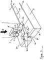
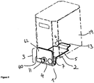
- FIG. 7 there is illustrated a unit for use in dispensing a liquid from the box 19 containing a liquid to be dispensed, the unit generally indicated by reference numeral 30.
- the mechanism 1 engaged with the gland 21 of the spout 11 and a box-supporting shelf 31 adapted to accommodate the mechanism 1.
- the box- supporting shelf 31 comprises an upper surface 32 for supporting the base 26 of the box 19.
- the upper surface 32 comprises a cavity 33 into which the capturing means 3 is accommodatable.
- the upper surface 32 further comprises an engagement means 34 within the cavity 33 which co-operates with at least one corresponding tab 35 provided on the capturing means 3.
- the tab 35 and engagement means 34 releasably lock the mechanism 1 to the box-supporting shelf 31.
- the engagement means 34 may be selected from the group comprising a magnet, a clip, complimentary engagement formations, and the like known to those skilled in the art to provide a releasable engagement means.
- the mechanism 1 engaged with a bag-in-box system is positioned into the cavity 33 of the supporting shelf 31 in the direction of arrow G.
- the tab 35 engages with the engagement means 34.
- the mechanism 1 can be released from the engagement means 34 of the supporting shelf 31 by activating an actuator 36 provided on the supporting shelf 31.
- a heat transfer contact plate 37 on the upper surface 32 of the supporting shelf 31.
- the heat transfer contact plate 37 When used with a capture mechanism without a platform 2, the heat transfer contact plate 37 is positioned to engage with the surface of the bag 24 through box aperture 22 to allow heat transfer to chill the bag 24, and ultimately the liquid stored in the bag 24.
- the contact plate 37 further provides additional support to the bag in the box and further acts to stop the bag bulging out of the box once the tear off sections are removed.
- the heat transfer contact plate 37 contacts the platform 2 engaged with the aperture 22 in the base 26 of the box 19 and the bag 24 accommodated therein.
- the platform 2 may be comprised of any thermally conductive material known to those skilled in the art, for example aluminium, to facilitate heat transfer from the heat transfer contact plate 37 to the liquid contained in the bag 24. As such, the liquid contained in the bag 24 is cooled rapidly.
- FIG 8 there is illustrated a cross section view of the mechanism 1 engaged with the spout 1 1 of a bag-in-box system and accommodated in the unit 30.
- the positioning of the portion 25 of the bag 24 in recess 7 is clearly illustrated in said Figure.
- the positioning of the mechanism 1 in the unit 30 is also more clearly illustrated, and how the raised lip 13 engages with the lip 23 in the base 26 of the box 19.
- contact plate 37 contacts the elongated section 5 of the platform 2, and heat transfer occurs, thereby chilling the liquid in the bag 24.
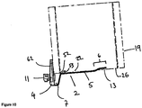
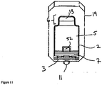
- Figures 9 to 12 there is illustrated an alternative example of capture mechanism.
- the illustrated embodiment is a slim-line version of the capture mechanism described above, and reference numerals used above are also used here to annotate the various features of the mechanism.
- the illustrated example is suitable for use in automatic dispensing units.
- the capture mechanism comprises a platform 2 and a capturing means 3.
- the platform 2 is adapted to engage with and support the base of the box, while the capturing means 3 releasably engages with the platform 2 to capture the spout 11 (as described for Figure 2 ).
- the capturing means 3 comprises a block 60 having a coupling member 62 and a spout-receiving portion 4, which is adapted to co-operate with the coupling member 62.
- the coupling member 62 and spout-receiving portion 4 are slimmer in construction than the capture mechanism described above for Figures 1 to 8 .
- the platform 2 comprises an elongated section 5 extending distal of the capturing means 3 and a flange 6 at the distal end of the elongated section 5.
- the spout- receiving portion 4 co-operates with the coupling member 62 by a co-operating section 12 (not shown).
- the platform 2 further comprises a recess 7 to accommodate the portion of the bag pulled out of the box in the spout's dispensing position.
- the coupling member 62 further comprises a locking means 9 (not shown). Both the coupling member 62 and spout-receiving portion 4 comprise complementary male and female formations (not shown).
- the coupling member 62 is pivotally attached to the spout-receiving portion 4 by hinge 16.
- the elongated section 5 of the platform 2 is adapted to cover the box's base aperture 22 to prevent the bag from protruding out through the aperture. Cooling of the bag is then affected via the platform 2.
- the weight of the liquid in the bag will maintain direct and close contact between the bag and the upper face of the section of the platform 2 covering aperture 22.
- the underside of this section of the platform 2 can then be brought into direct contact with a heat transfer contact plate or shelf.
- a flange 6 is provided at the distal end of the elongated section 5 to maintain and secure the platform 2 against the base of the box against the gravitational pressure of the fluid-filled bag.
- Flange 6 is tucked inside aperture 22.
- Flange 6 comprises a raised lip portion 13 that is adapted to engage with the interior back wall 40 of the box.
- the platform 2 further comprises a stepped ledge 52 configured to engage with aperture 50 provided to allow a portion 25 of a bag 24 to be pulled through the opening of the box 19 prior to engaging the mechanism 1 with the bag-in-box system, as illustrated in Figures 4 and 5 .
- the stepped ledge 52 rests on an edge 53 of the aperture 50 inside the base 26 to secure the platform 2 inside the box 19.
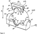
- FIG. 13 to 16 there is illustrated an exploded perspective view of a mechanism according to one embodiment of the present invention.
- the mechanism is for use with the aforementioned bag-in-box dispensing systems.
- the mechanism is generally indicated by the reference numeral 101.
- the capture mechanism comprises a tap capture base 102 and a coupling member 103.
- the tap capture base 102 is adapted to engage with and support the base of the box, while the coupling member 103 releasably engages with the base 102 to capture the spout (not shown).
- the coupling member 103 comprises a block 105 having a substantially U-shaped channel 104 to engage with and accommodate a gland in fluid communication with the spout (not shown).
- the gland is the portion of the bag to which the bag's dispensing spout is attached.
- the coupling member 103 co-operates with the base 102 by a co-operating section 106.
- a tether 170 is provided between coupling member 103 and base 102.
- the tether 170 is flexible and may be a plastic wire, cable tie or similar and prevents the coupling member being lost or misappropriated.
- tether 170 allows for the full 360 degree movement of the respective parts of the tap capture mechanism (as against just a "hinged” up and down movement) thus making the actual placement and capture of the gland easier in the tap capture mechanism.
- a tether may be provided on any of the aforementioned embodiments of capture mechanism of the present invention between any two or more cooperating or associated parts.
- the coupling member 103 further comprises a locking means 109, 110.
- the locking means 109, 110 is pivotally connected at sides 111, 112 of the coupling member 103.
- the co-operating section 106 comprises corresponding formations 113,114 which accommodate the locking means 109,110.
- the formations 113,114 may be configured to a snap-fit configuration.
- Both the coupling member 103 and co-operating section 106 comprise complementary male and female formations 115,116. In the current embodiment as illustrated in Figure 13 , the male formation 115 is shown on the coupling member 103, while the female formation 116 is shown on the co-operating section 106.
- the co-operating portion 106 further comprises a substantially U-shaped channel 18 to engage with and accommodate the bag's gland.
- the substantially U-shaped channels 104,118 further comprise stepped ridges 119, 120 to further accommodate the spout of the bag of the bag-in-box system.
- the coupling member 103 is placed against a front face of a box of a bag-in-box system, with the spout in a low dispensing position through an aperture in the base of the box.
- the coupling member 103 is moved in the direction of arrow A to releasably engage with the co-operating portion 106 of the base 102.
- the gland of the spout is secured resting within the substantially circular aperture formed by U-shaped channels 104 and 118.
- the neck of the spout protruding thought the aperture in the closed capture mechanism is then additionally supported by stepped ridges 119, 120 ensuring that the spout 111 is secured and maintained in a low and static dispensing position.
- a universal gland capturing saddle (not shown) may be reversibly secured either around the gland or within the substantially U-shaped channels 104,118.
- the universal gland capturing saddle can adapt to the shape and/or size of any gland used in bag-in-box systems.
- the base 102 further comprises a pair of stops 122,123 and shelves 124,125 juxtapositioned the co-operating portion 106.
- the stops 122,123 and shelves 124,125 project inwardly (in a direction towards the box) from the co-operating portion 106.
- the shelves 124,125 function as the platform as they support and hence cooperate with the base of the box in use.
- the shelves act to support and maintain the base of the box at a height above the dispensing spout when captured between base 102 and coupling member 103.
- the stops 122, 123 abut the front face of the box, not only to support same, but also to maintain the box a sufficient distance from the spout when captured to ensure ample room for the portion of bag rear of the spout to project freely out of the box.
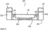
- Figure 14 shows the top view of the coupling member 103/ base 102 combination.
- the coupling member 103 is shown having a front face 130 and back face 131. When engaged with the base 102, the coupling member 103 lies flush against the co-operating portion 106 and remains within the boundary edge of the co-operating portion 106.
- the stops 122,123 and shelves 124,125 are located on side wings of the base 102, the side wings extending rearwardly (towards the box when in use) from the back face 131 of the central portion of the coupling member 103.
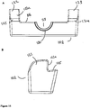
- Figures 15A and 15B show the front and side views, respectively, of the base 102.
- shelf 125 and the rear face 122a of stop 122 define a ledge to receive the lower front edge of the box.
- Figures 16A and 16B show the front and side views, respectively, of the coupling member 103.
- the block 105 comprises a front face 130 and back face 131.
- the front face 130 comprises an arched collar or archway 133 which engages with the gland of the bag of a bag-in-box system.
- the archway 133 is clearly illustrated in Figure 16A .
- the archway 133 comprises the substantially U-shaped channel 104 and stepped ridge 119.
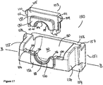
- FIG. 150 there is shown a further alternative embodiment of a capture mechanism of the present invention, generally indicated by reference numeral 150.
- the coupling member 103 is the same as that described for Figures 13 to 16 using the same reference numerals as used therein, and the tap capture base is generally indicated by reference numeral 151.
- parts 103 and 151 may be tethered together by a tether as per the previous embodiment described above.
- the base 151 comprises co-operating portion 106 as described above, that is, having corresponding formations 113,114 which accommodate the locking means 109,110 of the coupling member 103.
- the formations 113,114 may be configured to a snap-fit configuration.
- Both the coupling member 103 and co-operating section 106 of the base 151 comprise complementary male and female formations 115,116, respectively.
- the male formation 115 is shown on the coupling member 103
- the female formation 116 is shown on the co-operating section 106.
- the placement of the male and female formations 115,116 on the coupling member 103 and co-operating section 106 may be reversed.
- the male and female formations 115,116 could take alternate forms in terms of shape and size.
- the male and female formations 115,116 act as guides to ensure that the coupling member 103 and base 151 are in the correct orientation when securing the spout substantially under the level of the base of the box in a low dispensing position.
- the base 151 further comprises a substantially U-shaped channel 118 which further comprises stepped ridge 120 as described above.
- the channel 118 extends out from the base 151 forming a front face 152 similar to the front face 130 of the coupling member 103 described above. This is clearly illustrated in Figure 19B where the front face 152 extends out and away from a sidewall 154.
- the co-operating member 106 is recessed back from the front face 152, the front face 152 jutting out from the co-operating member 106.
- the base 152 further comprises sidewalls 154, 155 in communication with a stepped ledge 156, forming abutments 157,158.
- the abutments 157,158 are configured to engage with and support a front face of a box of a bag-in-box system.
- Ledge/shelf 156 is an extended version of shelves 124 and 125 of figures 13 to 16 and is configured to support a portion of the base of the box.
- the stepped ledge 156 extends downwards from the sidewalls 154,155 and perpendicular to a horizontal plane B-B to form an abutment 159.
- the base 151 is further configured to accommodate and support a portion of a bag pulled out from the box of a bag-in-box system, namely by a support means 160.
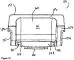
- the support means 160 comprises a well or cavity 161 formed by the sidewalls 154,155, the stepped ledge 156, and the co-operating portion 106. This is clearly seen in Figure 18 , a top plan view of the capture mechanism 150. In Figure 18 , the coupling member 103 lies flush with co-operating portion 106.
- Figure 19A illustrates a front view of the base 151 of the present invention.
- the abutment 159 extends downwards from the horizontal plane B-B from a base 162 of the support means 160.
- the capture mechanism of figures 17 to 19 has multiple functions. The mechanism not only captures the spout but also ensures that a desired orientation of captured spout relative to the box is maintained. The capture mechanism is used to capture the spout in a low dispensing position, beneath the base of the box, by maintaining the base of the box in a raised position relative to the captured spout position. Ledge 156 and abutments 157,158 act together to maintain the height and depth separation between the captured spout and base of box.
- the shelves 124, 125 and 156 extend a short distance rear of the capture mechanism, but may be deeper in alternative embodiments to support a greater portion of the base of the box.
- Both embodiments of capture mechanism from figures 13 to 19 may be used with a shelf of a dispensing unit similar to that shown in Figure 7 .
Description
- This invention relates generally to beverage dispensing, in particular to a capture mechanism for a dispensing spout of a bag-in-box dispensing system.
- In the field of beverage and liquid systems an apparatus, commonly known as a bag-in-box package, is used to store and dispense beverages such as soft drinks, fruit juices, water, or alcohol, but not limited thereto. Typically such bag-in-box packages comprise a collapsible bag or bladder disposed within a cardboard or plastic box. The bag is typically provided with a dispensing spout which protrudes through a side wall of the box for dispensing liquid stored within the bag.
- One of the problems associated with early prior art bag-in-box packaging is that the tap or spout needs to be supported within one of the side walls of the box and this results in an accumulation of the liquid in the area of the box below the level of the tap or spout. Thus the residual portion of liquid remaining in the bag is wasted. It is cumbersome and awkward for a user to open the nearly empty box, remove the bag and to squeeze the remaining fluid out from the box. This problem is amplified when a bag and box container is located within a dispensing unit wherein access to the bag is restricted.
- A number of attempts have been made to solve the above mentioned problems. European Patent No.
EP 1 520 836US 2003/0155372 , which discloses a bag-in-box apparatus where the interior base of the box is sloped or terraced downwards towards the spout of the bag such that gravity helps the liquid towards the spout, as shown infigure 1 by the dotted lines. However this solution has been shown to be unsatisfactory as it still results in waste liquid forming at the base of the box. - The inventors of the present invention have overcome these problems with an improved bag-in-box system for dispensing liquids, as described in International Patent Application No.
PCT/EP2008/065180 - A second improvement is to specifically introduce extra air into the bag which improves the dispensing rate of the fluid at lower volumes. (
GB 2 188 305A - Although the bag-in-box system of
PCT/EP2008/065180 PCT/EP2008/065180 a - The capture mechanism of the present invention overcomes some or all of the above- mentioned problems.
- The object of the present invention is to provide a capture mechanism for securely holding a dispensing spout of a flexible bag housed in a box in place in an external dispensing position beneath the base level of the box. It is a further object of the present invention to provide a unit for use in dispensing a liquid from a box housing a flexible bag containing liquid to be dispensed comprising a capture mechanism of the present invention and a box-supporting shelf adapted to accommodate the capture mechanism. It is a still further object of the present invention to provide a means to increase the speed of chill transfer to the fluid in the bag housed in the box. It is also an object of the present invention to provide a capture mechanism that facilitates the insertion of the box into a dispensing unit. It is a further object of the invention to provide a capture mechanism which easily interfaces with a dispensing unit.
- According to one aspect of the present invention, there is provided a capture mechanism for a dispensing spout of a bag-in-box liquid dispenser as set out in the appended claims,
- The capture mechanism comprises a shelf for supporting at least a portion of the base of the box. The shelf may lie in a plane higher than that of the means for capturing so as to ensure the base of the box is held above the spout when captured. The shelf may therefore act as stop means to maintain the base of the box in a relatively high position.
- The capture mechanism comprises means for abutting at least a portion of the front face of a box of a bag-in-box dispensor. The means for abutting may be substantially perpendicular to the shelf so as to form a roughly L-shaped corner into which the corner of the box may be accommodated. The shelf may be at an inclined angle to the base of the capture mechanism to as to angle the base of a box supported thereon, and tip it forward slightly. The capture mechanism may further comprise a well for accommodating a portion of the bag of a bag-in-box dispenser. The capture mechanism may comprise a block portion to securely accommodate the dispensing spout of a bag-in-box liquid dispenser. The block portion may comprise a coupling member for releasably engaging with a spout-receiving portion. The coupling member may be fully detachable from the spout-receiving portion. In addition/in contrast, the coupling member may be tethered to the spout-receiving portion. The coupling member and a co-operating section of the spout-receiving portion may comprise complementary male and female formations. At least one of said coupling member and said spout-receiving portion preferably comprises locking means. The locking means may be pivotally connected to either side of the coupling member and receivable into complimentary recesses in the spout receiving portion. The locking means may be released by squeezing their upper ends towards each other to release catches on the lower ends of each locking arm from corresponding catches within the complimentary recesses. Both the coupling member and the spout-receiving portion may be provided with a substantially U-shaped channel to engage about the gland of a spout to be captured.
- According to a further example there is provided a capture mechanism for a dispensing spout of a bag-in-box liquid dispenser, the dispenser adapted to enable said dispensing spout protrude through at least the base of the box, the capture mechanism comprising:
- a platform adapted to co-operate with the base of a box of a bag-in-box liquid dispenser; and
- means for capturing a dispensing spout of a bag-in-box liquid dispenser, wherein in use with the platform mating with the box of a bag-in-box liquid dispenser adapted to enable its dispensing spout protrude through at least the base of its box, the capturing means lies in a plane beneath the platform to maintain the dispensing spout in a low dispensing position relative to the level of the base of the box.
- One of the main advantages of the present invention is that the spout is kept in a low dispensing position, thereby negating the need to apply further manual force to the bag in the box to ensure that all the liquid has been dispensed therefrom.
- Preferably, the spout is adapted to be dropped down to a low dispensing position such that the spout is positioned at a level under the base of the container in use. This provides a gravitational well to urge the liquid from the bag to be dispensed via said spout. It will be appreciated that the liquid flow rate is maximised through the funnelling of the liquid in the bag into a lower level "gravitational well", before dispensing from the lowest level of the spout. As the box once opened is inverted and the gravitational pressure of the liquid is directed downwards into the box and not outwards through the now open box. This then allows the extra material of the bag (portion of the bag attached to the spout) to be easily manoeuvred into place into the tap capture mechanism without having to contend with the pressure exerted by the liquid contained within the bag.
- The capturing means may comprise a block to securely accommodate the dispensing spout of a bag-in-box liquid dispenser. The block may further comprise a locking means to releasably lock the capturing means to the platform. Preferably, the block comprises a coupling member for releasably engaging with a spout-receiving portion of the block. It is of course understood that the locking means of the coupling member and the cooperating section of the spout-receiving portion can comprise any locking means known to those skilled in the art other than male and female formations, for example, complementary threaded counterparts, fasteners, magnets, clips, and the like commonly used in the art.
- In one example, the coupling member is pivotally attached to the spout-receiving portion. In a further example, the coupling member is fully detachable from the spout-receiving portion. In this format, it is simply a locking "block" which allows a tap to be captured easily when the liquid in the bag of a bag-in-box system is not pressing against the box opening. For each of the above embodiments, the coupling member and a co-operating section of the spout-receiving portion comprise complementary male and female formations.
- In a further example, the block comprises a single unit having an open-sided internal channel configured to securely accommodate the dispensing spout. The block further comprises opposing jaws spaced-apart so as to provide an opening into the internal channel.
- According to invention further example, at least a portion of the platform is adapted to be received into an aperture in the base of a box of a bag-in-box dispenser. In an alternative example, the platform may form part of a shelf for supporting a box on which a box sits.
- It will also be appreciated that the platform may take different forms and shapes, and the level of cooperation between the base of the box and the platform may vary from only supporting the base or part of the base of the box to a more engaging contact wherein there becomes some level of inter-engagement between the two.
- According to one example, the platform is an integral part of the main body of the capture mechanism and take the form of shelf, which may be located behind the means for capturing on the box-facing side of the capture mechanism. It is desirable that the platform comprises:
- an elongated section extending distal of the capturing means to co-operate with the base of the box;
- (i) a stepped ledge at a proximal end of the elongated section to clip onto the base of the box; and
- (ii) a flange at a distal end of the elongated section receivable into an aperture in the base of the box, the stepped ledge and flange adapted to operate in tandem to secure the platform to the base of the box.
- A capture mechanism of this example may further comprise a recess in the platform or elsewhere to accommodate a portion of the bag attached to the dispensing spout protruding through at least the base of the box. The advantage of this recess is
that it can accommodate a portion of the bag protruding through at least the base of the box, thereby assisting in maintaining the spout in a low dispensing position when engaged with the capture mechanism. Further, the recess prevents the fluid-filled bag from bulging out of the bottom or front of the box (after the tear off portions of the box have been removed) when a user is trying to insert the box into a liquid dispenser. - In a further aspect, the flange is adapted to be received into an aperture in the base of the box. The flange comprises a raised lip at a distal end of the elongated section.
- It is desirable that each block or coupling member and spout-receiving portion comprise a substantially U-shaped channel. It will be appreciated however that the respective channels may take alternate forms to suit various shaped spouts/taps.
- Another example provides a capture mechanism for a dispensing spout of a bag-in-box liquid dispenser, the dispenser adapted to enable said dispensing spout protrude through at least the base of its box, the capture mechanism comprising: a shelf adapted to support at least a portion of the base of a box of a bag-in-box liquid dispenser; and
means for capturing a dispensing spout of a bag-in-box liquid dispenser, wherein in use with the shelf supporting at least a portion of the box of a bag-in-box liquid dispenser adapted to enable its dispensing spout protrude through at least the base of its box, the capturing means lies in a plane beneath the shelf to maintain the dispensing spout in a low dispensing position relative to the level of the base of the box. - The capture mechanism may further comprise a stop means or abutments to engage the front face of the box. The capture mechanism may further comprise a well or cavity to accommodate a portion of the bag projecting from the opening of the box in use. Two or more parts of the capture mechanism may be tethered together using a flexible tether or security cord, wire or strap. A flexible tether may be used to prevent any of the cooperating parts from becoming lost or misappropriated. The flexible nature of the tether allows for full 360 degree movement of any tethered parts.
- In a further aspect of the present invention, there is provided a unit for use in dispensing a liquid from a bag-in-box liquid dispenser, the dispenser adapted to enable a dispensing spout protrude through at least the base of the box, the unit comprising:
- a capture mechanism according to present invention and as described above, and
- a box-supporting shelf adapted to accommodate the capture mechanism. It is preferable that the supporting shelf comprises:
- an upper surface for supporting the base of a box, the upper surface having defined therein a cavity into which the capturing means of the capture mechanism is accommodatable. The supporting shelf may further comprise engagement means within the cavity to co-operate with at least one corresponding tab provided on said capturing means to releasably lock the capture mechanism to the supporting shelf.
- Preferably, the releasable engagement means is selected from the group comprising a magnet, a clip, and complimentary engagement formations. It will be readily understood by those skilled in the art that any other engagement means may be used that are described in the common general knowledge and known in the art.
- The supporting shelf may further comprise an actuator for releasing the capture mechanism from the releasable engagement means of the supporting shelf. This provides a convenient means for disengaging the capture mechanism from the unit in the event that all the liquid has been dispensed from the bag-in-box system and requires replacement.
- The supporting shelf may further comprise a heat transfer contact plate to engage with a bag in a bag-in-box dispenser. The contact plate helps drive chilling into the exposed bag by virtue of the bag being in contact with the plate.
- It should also be understood that a platform may form an integral part of the supporting shelf. The platform may also co-operate with the heat transfer contact plate to further extend the contact plate by association with the platform into the actual box on the inner side, thus extending the surface chilling area. This arrangement greatly speeds up the liquid chilling process.
- The advantages of the above-described unit is that the unit supports the body of the box after the tear off sections have been removed so as to prevent or minimise any bulging of the liquid in the bag out of the now exposed hole or holes in the box.
- A further advantage of the present invention is that the unit allows capture of a tap when fluid is not pressing against the tap and then subsequent placement of the now captured tap into a separate dispensing unit without having to make further movements to engage the tap with the tap capture mechanism. The only engagement is by the capturing means (and not the tap itself) with the dispensing mechanism. The box - now attached to the tap capture mechanism - can easily be then inserted into a cooling shelf of the dispenser, with the tap capture mechanism now acting as a centring and locking mechanism to ensure that the box is properly aligned on the cooling surfaces of the heat transfer contact plate and that the tap capture mechanism (and hence the bag and box and tap) is easily centred into the correct dispensing position, with minimal further input from the user.
- A further advantage of the heat transfer contact plate is that when in use, the tap capture mechanism extends into the box, contacts the heat transfer contact plate, and at the same time is in direct contact with the bag (the protective cardboard outer having been removed), thereby speeding up the heat transfer to chill the liquid in the bag and preventing the bag from bulging out of the box once the tear-off sections of the box have been removed.
- The invention will be more clearly understood from the following description of an embodiment thereof, given by way of example only, with reference to the accompanying drawings, in which:-
-
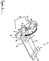
Figure 1 illustrates a perspective view of an example capture mechanism. -
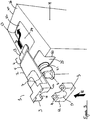
Figure 2 illustrates a diagrammatic representation of a perspective view of an alternative example of the capture mechanism engaging a bag-in-box system. -
Figure 3 illustrates a diagrammatic representation of an underside view of an example capture mechanism engaging a bag-in-box system. -
Figure 4 illustrates a top view representation of an example of a capture mechanism engaging a bag-in-box. -
Figure 5 illustrates a side view of the capture mechanism ofFigure 4 . -
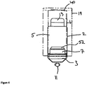
Figure 6 illustrates a perspective view of an example capture mechanism. -
Figure 7 illustrates a perspective view of a unit comprising an example capture mechanism engaged with a bag-in-box system. -
Figure 8 illustrates a side view in cross-section of the capture mechanism of any ofFigures 1 to 3 when engaged with a liquid dispensing unit. -
Figure 9 illustrates a perspective view of a further alternative example of a capture mechanism when engaging a bag-in-box system. -
Figure 10 illustrates a side view representation of the capture mechanism ofFigure 9 . -
Figure 11 illustrates atop view representation of the capture mechanism ofFigure 9 . -
Figure 12 illustrates a front view representation of the capture mechanism ofFigure 9 . -
Figure 13 illustrates an exploded perspective view of a capture mechanism of the present invention. -
Figure 14 illustrates a top plan view of the capture mechanism ofFigure 13 . -
Figure 15A illustrates a front view representation of one piece of the capture mechanism ofFigure 13 . -
Figure 15B illustrates a side view representation ofFigure 15A . -
Figure 16A illustrates a front view of a further piece of the capture mechanism of theFigure 13 . -
Figure 16B illustrates a side view representation ofFigure 16A . -
Figure 17 illustrates an exploded perspective view of an alternative embodiment of the capture mechanism of the present invention. -
Figure 18 illustrates a top view representation of the alternative illustrated inFigure 17 . -
Figure 19A illustrates a front view representation of one piece of the capture mechanism ofFigure 17 . -
Figure 19B illustrates a side view representation of the piece of the capture mechanism ofFigure 19A . - It should be readily apparent to one of ordinary skill in the art that the embodiments disclosed herein below represent generalised embodiments only, and that other arrangements are possible and are embraced by the present invention.
- In
Figure 1 there is illustrated a side view in cross section of an example mechanism. The mechanism is for use with bag-in-box dispensing systems, which generally comprise a box having formed therein an opening near its base to allow a dispensing spout project from the box, and in some instances allow a portion of the bag to be substantially pulled through the opening provided therein, so that the spout projects substantially under the level of the base of said box in a low dispensing position. The mechanism is generally indicated by thereference numeral 1. The capture mechanism comprises aplatform 2 and a capturing means 3. Theplatform 2 is adapted to engage with and support the base of the box, while the capturing means 3 releasably engages with theplatform 2 to capture the spout 11 (seeFigure 2 ). - The capturing means 3 comprises a
block 60 having acoupling member 62 and a spout-receivingportion 4, which is adapted to co-operate with thecoupling member 62. Theplatform 2 comprises anelongated section 5 extending distal of the capturing means 3 and aflange 6 at the distal end of theelongated section 5. The spout-receivingportion 4 co-operates with thecoupling member 62 by aco-operating section 12. - The
platform 2 further comprises arecess 7 to accommodate the portion of the bag pulled out of the box in the spout's dispensing position. - The
coupling member 62 further comprises a locking means 9. Thecoupling member 62 and spout-receivingportion 4 each comprise a substantiallyU-shaped channel gland 21 in fluid communication with the spout 11 (seeFigure 2 ). Both thecoupling member 62 and spout-receivingportion 4 comprise complementary male andfemale formations Figure 1 , themale formation 14 is shown on thecoupling member 62, while thefemale formation 15 is shown on the spout-receivingportion 4. It should be understood by the skilled artisan that the placement of the male andfemale formations coupling member 62 and spout-receivingportion 4 may be reversed. It should also be understood by the skilled artisan that the male andfemale formations - As shown in the example as illustrated in
Figure 1 , thecoupling member 62 is pivotally attached to the spout-receivingportion 4 byhinge 16. Thecoupling member 62 pivots about thehinge 16 in the direction of arrow A to engage with theco-operating section 12 of the spout-receivingsection 4. The male andfemale formations U-shaped channels gland 21 in fluid communication with thespout 11 of a bag-in-box system in the dispensing system (explained in more detail below, seeFigures 5 and6 ). - As illustrated in
Figure 2 , there is shown a further example mechanism where thecoupling member 62 is fully detachable from the capturing means 3. In use, thecoupling member 62 is placed against a front face of abox 19 of a bag- in-box system, with thespout 11 in a low dispensing position through anaperture 50. Thecoupling member 62 is moved in the direction of arrow B to releasably engage with theco-operating portion 12 of the capturing means 3. When thecoupling member 62 and spout-receivingportion 4 have engaged, thegland 21 of thespout 11 is secured within the substantiallyU-shaped channels spout 11 is secured in a low dispensing position. - In an alternative example, a universal gland capturing saddle (not shown) may be reversibly secured either around the
gland 21 or within the substantiallyU-shaped channels gland 21 as shown inFigure 2 . - In a further alternative example, the
block 60 comprises a single unit having an open-sided internal channel configured to securely accommodate the dispensing spout. The block comprises opposing jaws spaced apart so as to provide an opening into the internal channel. It is advantageous to have the jaws biased closely together at rest but moveable apart to increase the opening into the internal channel. The opening provides a means by which theblock 60 can be pushed over thegland 21 , to force thegland 21 into the internal channel, wherein it is securely engaged. When theblock 60 is pushed over thegland 21 and the gland secured within the internal channel, the jaws return to their original biased closed/nearly closed position trapping the gland within the block. -
Figure 3 shows the underside of the arrangement shown inFigure 2 , wherein it can be seen that thebox 19, for which this example of capture mechanism is designed for use with, is provided with asecond aperture 22 in itsbase 26. The primary purpose of thissecond aperture 22 is to gain access to the bag inside thebox 19. Access to the internal bag is desirable to enable a heat transfer contact plate to be brought into direct contact with the bag to cool the liquid contained therein. In prior art arrangements, the box may be placed directly on a cooling shelf or plate however this is undesirable as the weight of the liquid in the bag can force the bag to bulge out through the aperture in the base of the box. This problem is overcome by theelongate section 5 of theplatform 2 of the capture mechanism shown inFigures 1 to 3 . As shown inFigure 7 , theelongated section 5 of theplatform 2 is adapted to cover the box'sbase aperture 22 to prevent the bag from protruding out through the aperture. Cooling of the bag is then affected via theplatform 2. The weight of the liquid in the bag will maintain direct and close contact between the bag and the upper face of the section of theplatform 2 coveringaperture 22. The underside of this section of theplatform 2 can then be brought into direct contact with a heat transfer contact plate or shelf. - A
flange 6 is provided at the distal end of theelongated section 5 to maintain and secure theplatform 2 against the base of the box against the gravitational pressure of the fluid-filled bag. In use,flange 6 is tucked insideaperture 22 as shown by arrow D inFigure 3 .Flange 6 comprises a raisedlip portion 13 that is adapted to engage with theinterior back wall 40 of the box. - The
platform 2 further comprises a steppedledge 52 configured to engage withaperture 50 provided to allow aportion 25 of abag 24 to be pulled through the opening of thebox 19 prior to engaging themechanism 1 with the bag-in-box system, as illustrated inFigures 4 and5 . In use, when theplatform 2 is received in theapertures box 19, the steppedledge 52 rests on anedge 53 of theaperture 50 inside the base 26 to secure theplatform 2 inside thebox 19.Figure 3 also illustrates by way of example the steps by which the capture mechanism I may engage with a bag-in-box system. For instance, the first step is where, when thebox 19 is positioned so that thebase 26 of thebox 19 is facing upwards to a user, theplatform 2 of themechanism 1 engages with theapertures base 26 of thebox 19. Theplatform 2 engages with thebase 26 of thebox 19 via raisedlip 13 offlange 6. The raisedlip 13 is inserted into thebase 26 viaaperture 22 in the direction of arrow D. The raisedlip 13 slips through theaperture 22 and rests on anedge 23 of theaperture 22 inside thebase 26 and abuts against theback wall 40 ofbox 19. The steppedledge 52 rests on theedge 53 of the aperture 50 (seeFigures 4 and5 ). A portion of theelongated section 5 of theplatform 2 and thebox engaging means 6 are in contact with thebag 24 accommodated within thebox 19. The contact between thebag 24,elongated section 5, and engagingmeans 6 prevent thebag 24 from bulging and protruding throughaperture 22 ofbox 19. When theplatform 2 is in an engaged position withapertures gland 21 of thespout 11 is accommodated within the substantiallyU-shaped channel 18 of the spout-receivingportion 4, and theportion 25 of thebag 24 is accommodated in the recess 7 (not shown - seeFigure 8 ). Theportion 25 is pulled through the opening of thebox 19 prior to engaging themechanism 1 with the bag-in-box system. - The second step is to secure the
spout 11 in a low dispensing position by positioning thecoupling member 62 over thegland 21 of thespout 11 and moving thecoupling member 62 in the direction of arrow E. The male andfemale formations coupling member 62 and co-operatingportion 12 engage, thereby locking thecoupling member 62 and capturing means 3 together. Thespout 11 is now secured in a low dispensing position. - In an alternative example, a universal saddle (not shown) can also be used in conjunction with
coupling member 62 and spout-receivingportion 4 to secure the spout
I1 in a low dispensing position as explained above. The universal saddle is configured to adapt to any shape and/or size ofgland 21 used in the prior art bag-in-box systems, as explained above. - As illustrated in
Figure 6 , there is shown a further alternative example of a capture mechanism, generally indicated byreference numeral 20, wherein thecoupling member 62 is pivotally attached to the spout-receivingportion 4 byhinge 16. In this embodiment, the spout-receivingportion 4 is not attached to a platform. As such, thecapture mechanism 20 ofFigure 6 does not engage with the
base of the box due to the lack of a platform, but instead engages with thespout 11 of a bag-in-box system. Thecoupling member 62 pivotally moves in an arc, as indicated by arrow C, to releasably engage with the spout-receivingportion 4. When in use, thecapture mechanism 20 is moved toward thespout 11 in the direction of arrow F when in a disengaged state. Thecoupling member 62 is pivoted abouthinge 16 in the direction of arrow C, engaging with thegland 21 of thespout 11, and releasably cooperating with co-operatingportion 12 of the spout-receivingportion 4. The male andfemale formations capture mechanism 20 engage, thereby securing thespout 11 in a low dispensing position. - In an alternative example, a universal saddle (not shown) can also be used in conjunction with the
capture mechanism 20 to secure thespout 11 in a low dispensing position as explained above. The universal saddle is configured to adapt to any shape and/or size ofgland 21 used in the prior art bag-in-box systems, as explained above. In a still further embodiment, thecoupling member 3/spout-receivingportion 4 ofFigures 1 to 5 andcapture mechanism 20 ofFigure 6 can each be comprised of a single block (not shown) having a substantially circular open sided internal channel configured to securely accommodate thegland 21 of thespout 1 1. The block comprises opposing jaws spaced apart so as to provide an opening into the internal channel. It is advantageous to have the jaws biased closely together at rest but moveable apart to increase the opening into the internal channel. The opening provides a means by which the unit can be pushed over thegland 21 , to force thegland 21 into the internal channel, wherein it is securely engaged. When the block is pushed over thegland 21 and the gland secured within the internal channel, the jaws return to their original biased closed/nearly closed position trapping the gland within the block. - In
Figure 7 , there is illustrated a unit for use in dispensing a liquid from thebox 19 containing a liquid to be dispensed, the unit generally indicated byreference numeral 30. There is shown themechanism 1 engaged with thegland 21 of thespout 11 and a box-supportingshelf 31 adapted to accommodate themechanism 1. The box- supportingshelf 31 comprises anupper surface 32 for supporting thebase 26 of thebox 19. Theupper surface 32 comprises acavity 33 into which the capturing means 3 is accommodatable. Theupper surface 32 further comprises an engagement means 34 within thecavity 33 which co-operates with at least one correspondingtab 35 provided on the capturing means 3. Thetab 35 and engagement means 34 releasably lock themechanism 1 to the box-supportingshelf 31. - The engagement means 34 may be selected from the group comprising a magnet, a clip, complimentary engagement formations, and the like known to those skilled in the art to provide a releasable engagement means.
- The
mechanism 1 engaged with a bag-in-box system is positioned into thecavity 33 of the supportingshelf 31 in the direction of arrow G. Thetab 35 engages with the engagement means 34. Themechanism 1 can be released from the engagement means 34 of the supportingshelf 31 by activating anactuator 36 provided on the supportingshelf 31. - In a further example, there is provided a heat
transfer contact plate 37 on theupper surface 32 of the supportingshelf 31. When used with a capture mechanism without aplatform 2, the heattransfer contact plate 37 is positioned to engage with the surface of thebag 24 throughbox aperture 22 to allow heat transfer to chill thebag 24, and ultimately the liquid stored in thebag 24. Thecontact plate 37 further provides additional support to the bag in the box and further acts to stop the bag bulging out of the box once the tear off sections are removed. - Alternatively, when being used with one of the platform-based examples of capture mechanism, the heat
transfer contact plate 37 contacts theplatform 2 engaged with theaperture 22 in thebase 26 of thebox 19 and thebag 24 accommodated therein. Theplatform 2 may be comprised of any thermally conductive material known to those skilled in the art, for example aluminium, to facilitate heat transfer from the heattransfer contact plate 37 to the liquid contained in thebag 24. As such, the liquid contained in thebag 24 is cooled rapidly. - When the
mechanism 1 is engaged with theunit 30, there is anopening 38 at afront face 39 of theshelf 31 to allow a user access to the liquid dispensed from thespout 1 1. - In
Figure 8 there is illustrated a cross section view of themechanism 1 engaged with thespout 1 1 of a bag-in-box system and accommodated in theunit 30. The positioning of theportion 25 of thebag 24 inrecess 7 is clearly illustrated in said Figure. Furthermore, the positioning of themechanism 1 in theunit 30 is also more clearly illustrated, and how the raisedlip 13 engages with thelip 23 in thebase 26 of thebox 19. As can be further seen inFigure 8 ,contact plate 37 contacts theelongated section 5 of theplatform 2, and heat transfer occurs, thereby chilling the liquid in thebag 24. InFigures 9 to 12 there is illustrated an alternative example of capture mechanism. The illustrated embodiment is a slim-line version of the capture mechanism described above, and reference numerals used above are also used here to annotate the various features of the mechanism. The illustrated example is suitable for use in automatic dispensing units. The capture mechanism comprises aplatform 2 and a capturing means 3. Theplatform 2 is adapted to engage with and support the base of the box, while the capturing means 3 releasably engages with theplatform 2 to capture the spout 11 (as described forFigure 2 ). - The capturing means 3 comprises a
block 60 having acoupling member 62 and a spout-receivingportion 4, which is adapted to co-operate with thecoupling member 62. In the current embodiment, thecoupling member 62 and spout-receivingportion 4 are slimmer in construction than the capture mechanism described above forFigures 1 to 8 . Theplatform 2 comprises anelongated section 5 extending distal of the capturing means 3 and aflange 6 at the distal end of theelongated section 5. The spout- receivingportion 4 co-operates with thecoupling member 62 by a co-operating section 12 (not shown). - The
platform 2 further comprises arecess 7 to accommodate the portion of the bag pulled out of the box in the spout's dispensing position. - The
coupling member 62 further comprises a locking means 9 (not shown). Both thecoupling member 62 and spout-receivingportion 4 comprise complementary male and female formations (not shown). - In the example as illustrated in
Figures 9 to 12 , thecoupling member 62 is pivotally attached to the spout-receivingportion 4 byhinge 16. As shown inFigure 10 theelongated section 5 of theplatform 2 is adapted to cover the box'sbase aperture 22 to prevent the bag from protruding out through the aperture. Cooling of the bag is then affected via theplatform 2. The weight of the liquid in the bag will maintain direct and close contact between the bag and the upper face of the section of theplatform 2 coveringaperture 22. The underside of this section of theplatform 2 can then be brought into direct contact with a heat transfer contact plate or shelf. - A
flange 6 is provided at the distal end of theelongated section 5 to maintain and secure theplatform 2 against the base of the box against the gravitational pressure of the fluid-filled bag. In use,flange 6 is tucked insideaperture 22.Flange 6 comprises a raisedlip portion 13 that is adapted to engage with theinterior back wall 40 of the box. Theplatform 2 further comprises a steppedledge 52 configured to engage withaperture 50 provided to allow aportion 25 of abag 24 to be pulled through the opening of thebox 19 prior to engaging themechanism 1 with the bag-in-box system, as illustrated inFigures 4 and5 . In use, when theplatform 2 is received in theapertures box 19, the steppedledge 52 rests on anedge 53 of theaperture 50 inside the base 26 to secure theplatform 2 inside thebox 19. - In
Figures 13 to 16 there is illustrated an exploded perspective view of a mechanism according to one embodiment of the present invention. The mechanism is for use with the aforementioned bag-in-box dispensing systems. The mechanism is generally indicated by the reference numeral 101. The capture mechanism comprises atap capture base 102 and acoupling member 103. Thetap capture base 102 is adapted to engage with and support the base of the box, while thecoupling member 103 releasably engages with the base 102 to capture the spout (not shown). - The
coupling member 103 comprises ablock 105 having a substantiallyU-shaped channel 104 to engage with and accommodate a gland in fluid communication with the spout (not shown). The gland is the portion of the bag to which the bag's dispensing spout is attached. Thecoupling member 103 co-operates with the base 102 by aco-operating section 106. Atether 170 is provided betweencoupling member 103 andbase 102. Thetether 170 is flexible and may be a plastic wire, cable tie or similar and prevents the coupling member being lost or misappropriated. The flexible nature of thetether 170 allows for the full 360 degree movement of the respective parts of the tap capture mechanism (as against just a "hinged" up and down movement) thus making the actual placement and capture of the gland easier in the tap capture mechanism. Such a tether may be provided on any of the aforementioned embodiments of capture mechanism of the present invention between any two or more cooperating or associated parts. - The
coupling member 103 further comprises a locking means 109, 110. The locking means 109, 110 is pivotally connected atsides 111, 112 of thecoupling member 103. Theco-operating section 106 comprises corresponding formations 113,114 which accommodate the locking means 109,110. The formations 113,114 may be configured to a snap-fit configuration. Both thecoupling member 103 andco-operating section 106 comprise complementary male and female formations 115,116. In the current embodiment as illustrated inFigure 13 , themale formation 115 is shown on thecoupling member 103, while thefemale formation 116 is shown on theco-operating section 106. It should be understood by the skilled artisan that the placement of the male and female formations 115,116 on thecoupling member 103 andco-operating section 106 may be reversed. It should also be understood by the skilled artisan that the male and female formations 115,116 could take alternate forms in terms of shape and size. The male and female formations 115,116 act as guides to ensure that thecoupling member 103 andbase 102 are in the correct orientation when securing the spout substantially under the level of the base of the box in a low dispensing position. Theco-operating portion 106 further comprises a substantiallyU-shaped channel 18 to engage with and accommodate the bag's gland. The substantially U-shaped channels 104,118 further comprise steppedridges - In use, the
coupling member 103 is placed against a front face of a box of a bag-in-box system, with the spout in a low dispensing position through an aperture in the base of the box. Thecoupling member 103 is moved in the direction of arrow A to releasably engage with theco-operating portion 106 of thebase 102. When thecoupling member 103 andco-operating portion 106 have engaged, the gland of the spout is secured resting within the substantially circular aperture formed byU-shaped channels ridges - In an alternative embodiment, a universal gland capturing saddle (not shown) may be reversibly secured either around the gland or within the substantially U-shaped channels 104,118. The universal gland capturing saddle can adapt to the shape and/or size of any gland used in bag-in-box systems.
- The base 102 further comprises a pair of stops 122,123 and shelves 124,125 juxtapositioned the
co-operating portion 106. In use, the stops 122,123 and shelves 124,125 project inwardly (in a direction towards the box) from theco-operating portion 106. It will be appreciated that the shelves 124,125 function as the platform as they support and hence cooperate with the base of the box in use. The shelves act to support and maintain the base of the box at a height above the dispensing spout when captured betweenbase 102 andcoupling member 103. Thestops -
Figure 14 shows the top view of thecoupling member 103/base 102 combination. Thecoupling member 103 is shown having afront face 130 andback face 131. When engaged with thebase 102, thecoupling member 103 lies flush against theco-operating portion 106 and remains within the boundary edge of theco-operating portion 106. The stops 122,123 and shelves 124,125 are located on side wings of thebase 102, the side wings extending rearwardly (towards the box when in use) from theback face 131 of the central portion of thecoupling member 103. -
Figures 15A and 15B show the front and side views, respectively, of thebase 102. As shown inFigure 15B ,shelf 125 and therear face 122a ofstop 122 define a ledge to receive the lower front edge of the box. As shown inFigure 15A , it is preferable thatshelf 125 is inclined relative to the base ofbase 102. This results in an acute angle betweenshelf 125 andface 122a. Such an incline aids to support the box in a tilted orientation, wherein the base of the box is lower at its leading/front edge than at its rear. This aids to facilitate complete emptying of the liquid being dispensed. -
Figures 16A and 16B show the front and side views, respectively, of thecoupling member 103. As illustrated inFigure 16B , theblock 105 comprises afront face 130 andback face 131. Thefront face 130 comprises an arched collar orarchway 133 which engages with the gland of the bag of a bag-in-box system. Thearchway 133 is clearly illustrated inFigure 16A . Thearchway 133 comprises the substantiallyU-shaped channel 104 and steppedridge 119. - As illustrated in
Figures 17 to 19 , there is shown a further alternative embodiment of a capture mechanism of the present invention, generally indicated byreference numeral 150. In this embodiment, thecoupling member 103 is the same as that described forFigures 13 to 16 using the same reference numerals as used therein, and the tap capture base is generally indicated byreference numeral 151. Although not shown in these figures,parts base 151 comprisesco-operating portion 106 as described above, that is, having corresponding formations 113,114 which accommodate the locking means 109,110 of thecoupling member 103. The formations 113,114 may be configured to a snap-fit configuration. Both thecoupling member 103 andco-operating section 106 of the base 151 comprise complementary male and female formations 115,116, respectively. In the current embodiment as illustrated inFigure 17 , themale formation 115 is shown on thecoupling member 103, while thefemale formation 116 is shown on theco-operating section 106. It should be understood by the skilled artisan that the placement of the male and female formations 115,116 on thecoupling member 103 andco-operating section 106 may be reversed. It should also be understood by the skilled artisan that the male and female formations 115,116 could take alternate forms in terms of shape and size. The male and female formations 115,116 act as guides to ensure that thecoupling member 103 andbase 151 are in the correct orientation when securing the spout substantially under the level of the base of the box in a low dispensing position. - The base 151 further comprises a substantially
U-shaped channel 118 which further comprises steppedridge 120 as described above. Thechannel 118 extends out from the base 151 forming afront face 152 similar to thefront face 130 of thecoupling member 103 described above. This is clearly illustrated inFigure 19B where thefront face 152 extends out and away from asidewall 154. As such, the co-operatingmember 106 is recessed back from thefront face 152, thefront face 152 jutting out from the co-operatingmember 106. The base 152 further comprisessidewalls ledge 156, forming abutments 157,158. The abutments 157,158 are configured to engage with and support a front face of a box of a bag-in-box system. Ledge/shelf 156 is an extended version ofshelves figures 13 to 16 and is configured to support a portion of the base of the box. The steppedledge 156 extends downwards from the sidewalls 154,155 and perpendicular to a horizontal plane B-B to form anabutment 159. - The
base 151 is further configured to accommodate and support a portion of a bag pulled out from the box of a bag-in-box system, namely by a support means 160. The support means 160 comprises a well orcavity 161 formed by the sidewalls 154,155, the steppedledge 156, and theco-operating portion 106. This is clearly seen inFigure 18 , a top plan view of thecapture mechanism 150. InFigure 18 , thecoupling member 103 lies flush withco-operating portion 106. -
Figure 19A illustrates a front view of thebase 151 of the present invention. As can be clearly seen here, theabutment 159 extends downwards from the horizontal plane B-B from abase 162 of the support means 160. As with the embodiment shown inFigures 13 to 16 , it will be appreciated that the capture mechanism offigures 17 to 19 has multiple functions. The mechanism not only captures the spout but also ensures that a desired orientation of captured spout relative to the box is maintained. The capture mechanism is used to capture the spout in a low dispensing position, beneath the base of the box, by maintaining the base of the box in a raised position relative to the captured spout position.Ledge 156 and abutments 157,158 act together to maintain the height and depth separation between the captured spout and base of box. - It will be further appreciated that in either embodiment shown in
figures 13 to 19 , theshelves - One difference between the embodiment in
figures 13 to 16 and that infigures 17 to 19 is that the latter captures the spout in a position well proud of the opening in the box. This may be more suitable for a unit wherein it is desirable for the spout to be manually activated and hence is required to be accessible from the front of the unit. The former embodiment wherein the capture mechanism stands less proud of the box when the spout is captured may be used when the tap is not manually activated to provide a more streamlined arrangement. For the former embodiment, less bag is required to be pulled from the box and hence no well is required to accommodate same. - Both embodiments of capture mechanism from
figures 13 to 19 may be used with a shelf of a dispensing unit similar to that shown inFigure 7 . - The words "comprises/comprising" and the words "having/including" when used herein with reference to the present invention are used to specify the presence of stated features, integers, steps or components but does not preclude the presence or addition of one or more other features, integers, steps, components or groups thereof.
- It is appreciated that certain features of the invention, which are, for clarity, described in the context of separate embodiments, may also be provided in combination in a single embodiment. Conversely, various features of the invention, which are, for brevity, described in the context of a single embodiment, may also be provided separately or in any suitable sub-combination.
Claims (15)
- A capture mechanism (101) for a dispensing spout of a bag-in-box liquid dispenser, the dispenser adapted to enable said dispensing spout protrude through at least the base of its box, the capture mechanism comprising:a tap capture base (102) comprising a spout receiving portion and side wings extending rearwardly from the spout receiving portion; anda coupling member (103) adapted to cooperate with the spout receiving portion of the tap capture base;wherein the spout receiving portion of the tap capture base and the coupling member each comprise a substantially U-shaped channel (104, 118), which cooperate to define a substantially circular aperture for accommodating and capturing the spout of a bag in box liquid dispenser; andcharacterised in that each side wing of the tap capture base comprises:at least one box-supporting shelf (124, 125, 156) for maintaining the base of the box in a raised position relative to its spout when said spout is captured between the tap capture base and the coupling member; andat least one abutment (122, 123, 157, 158) arranged to abut the front face of the box and maintain the box at a sufficient distance from its spout when said spout is captured between the tap capture base and the coupling member, to maintain the captured spout in a position proud of the box to ensure ample room for a portion of bag rear of the spout project freely out of the box.
- The capture mechanism of claim 1 further comprising a well (161) for accommodating the portion of the bag rear of the spout.
- A capture mechanism according to any preceding claim, wherein the coupling member is fully detachable from the spout-receiving portion.
- A capture mechanism according to claim 1 or claim 2, wherein the coupling member is tethered to the spout-receiving portion.
- A capture mechanism according to any preceding claim, wherein the coupling member and a co-operating section of the spout-receiving portion comprise complementary male (115) and female (116) formations.
- A capture mechanism according to any preceding claim, wherein at least one of said coupling member and said spout-receiving portion comprises locking means.
- A capture mechanism according to any preceding claim, wherein each box-supporting shelf is inclined relative to the base of the tap capture base to support the box in a tilted orientation.
- A unit for use in dispensing a liquid from a bag-in-box liquid dispenser, the dispenser adapted to enable a dispensing spout protrude through at least the base of the box, the unit comprising:a capture mechanism according to any one of Claims 1 to 7 and a shelf adapted to accommodate the capture mechanism.
- A unit according to Claim 8, wherein the shelf comprises: an upper surface for supporting the base of a box, the upper surface having defined therein a cavity into which the capturing means of the capture mechanism is accommodatable.
- A unit according to Claim 9, wherein the shelf further comprises engagement means within the cavity to co-operate with at least one corresponding tab provided on said capturing means to releasably lock the capture mechanism to the shelf.
- A unit according to Claim 10, wherein the releasable engagement means is selected from the group comprising a magnet, a clip, and complimentary engagement formations.
- A unit according to any of Claims 8 to 11, wherein the shelf further comprises an actuator for releasing the capture mechanism from the releasable engagement means of the shelf.
- A unit according to any of Claims 8 to 11, wherein the shelf further comprises a heat transfer contact plate to engage with a bag in a bag-in-box dispenser and chill the liquid therein.
- A unit according to any of Claims 8 to 13, wherein the platform forms an integral part of the shelf.
- A unit according to Claim 13, wherein the platform co-operates with the heat transfer contact plate to further aid in chilling the liquid in the bag.
Applications Claiming Priority (3)
| Application Number | Priority Date | Filing Date | Title |
|---|---|---|---|
| IES20090635 IES20090635A2 (en) | 2009-08-18 | 2009-08-18 | A bag-in-box dispensing spout capture mechanism |
| IES20090964 IES20090964A2 (en) | 2009-08-18 | 2009-12-22 | A bag-in-box dispensing spout capture mechanism |
| PCT/EP2010/061991 WO2011020837A1 (en) | 2009-08-18 | 2010-08-17 | A bag-in-box dispensing spout capture mechanism |
Publications (2)
| Publication Number | Publication Date |
|---|---|
| EP2467327A1 EP2467327A1 (en) | 2012-06-27 |
| EP2467327B1 true EP2467327B1 (en) | 2016-12-14 |
Family
ID=46604800
Family Applications (1)
| Application Number | Title | Priority Date | Filing Date |
|---|---|---|---|
| EP10757051.7A Active EP2467327B1 (en) | 2009-08-18 | 2010-08-17 | A bag-in-box dispensing spout capture mechanism |
Country Status (6)
| Country | Link |
|---|---|
| US (1) | US8967433B2 (en) |
| EP (1) | EP2467327B1 (en) |
| AU (1) | AU2010285037B2 (en) |
| DK (2) | DK201070364A (en) |
| IE (2) | IES20090635A2 (en) |
| WO (1) | WO2011020837A1 (en) |
Families Citing this family (14)
| Publication number | Priority date | Publication date | Assignee | Title |
|---|---|---|---|---|
| IES20070805A2 (en) * | 2007-11-07 | 2008-10-15 | Aqueduct Invest Internat Ltd | System and method for containing and dispensing a liquid |
| IES20090635A2 (en) | 2009-08-18 | 2010-10-27 | Aqueduct Invest Internat Ltd | A bag-in-box dispensing spout capture mechanism |
| DE102010044861A1 (en) * | 2010-09-09 | 2012-03-15 | Squell Produktion Und Handel Gmbh | Dispensing device for at least one bag-in-box packaging |
| US9573736B2 (en) * | 2013-07-03 | 2017-02-21 | Scholle Ipn Corporation | Connector assembly for a self sealing fitment |
| US10294094B2 (en) * | 2015-04-07 | 2019-05-21 | Shomo, Llc | Containers having one or more sloped inner regions for providing an improved ability for dispensing liquids |
| MX2018003915A (en) * | 2015-09-28 | 2018-09-06 | Int Paper Co | Sump base dispensing system for bulk bin and bag combination. |
| US10611626B2 (en) * | 2015-10-30 | 2020-04-07 | A.C. Dispensing Equipment Inc. | Pinch valve for liquid dispenser |
| JP6045011B1 (en) * | 2016-04-30 | 2016-12-14 | 洪 瑟芬 | Bag in box |
| US9586803B1 (en) * | 2016-08-17 | 2017-03-07 | Tailor Made Products, Inc. | Bottle rack dispenser apparatus |
| US10526189B2 (en) * | 2017-05-11 | 2020-01-07 | Grabas Limited | Gravity fed viscous liquid and food product dispensing system |
| FR3076289A1 (en) * | 2017-12-29 | 2019-07-05 | Societe Viaplast | DEVICE FOR COMPLETELY EMPTYING LIQUIDS CONTAINED IN SOFT POCKETS PROTECTED BY A CARDBOARD PACKAGE AND HAVING A FAUCET GENERALLY CALLED BIBS |
| US11667512B2 (en) * | 2021-03-26 | 2023-06-06 | Henkel Ag & Co. Kgaa | Dispensing system for dispensing a liquid from a replacement container |
| US11873207B2 (en) * | 2021-11-30 | 2024-01-16 | World Wide Hagerty Inc. | Beverage-dispensing keg |
| ES1285311Y (en) * | 2021-12-20 | 2022-04-18 | Juan Milagros Pico | Tap for liquid containment containers |
Family Cites Families (18)
| Publication number | Priority date | Publication date | Assignee | Title |
|---|---|---|---|---|
| US268313A (en) * | 1882-11-28 | Thomas s | ||
| US3325058A (en) * | 1964-03-10 | 1967-06-13 | Jr Junius Mosby West | Electrically heated receptacles and disposable containers therefor |
| US3448897A (en) * | 1966-12-16 | 1969-06-10 | Ronald W Sterling | Apparatus for the storage and dispensing of liquids |
| GB2188305A (en) | 1986-03-25 | 1987-09-30 | Derrick Raymond Gatley | Lined containers for liquids |
| DE3914398C2 (en) * | 1989-04-29 | 2002-11-14 | Schenk Helga | Two-substance packaging, in particular two-substance liquid packaging with a pouring spout of the inner container that can be pulled outwards by punching out the outer carton |
| CA2015175A1 (en) * | 1990-04-23 | 1991-10-23 | Donald A. Brown | Method and apparatus for dispensing flowable hair products |
| GB2246764B (en) * | 1990-08-07 | 1994-05-18 | Anthony David Shaw | A drinks box dispenser for dispensing drinks held in a container within the dispenser |
| GB2273488B (en) * | 1992-12-17 | 1996-03-06 | Flomotion Ltd | Bulk container with removable tray |
| US5419448A (en) * | 1993-01-19 | 1995-05-30 | Watson; John | Knock down bulk storage container |
| AUPO777997A0 (en) * | 1997-07-09 | 1997-07-31 | Technosearch Pty. Limited | Improvements in containers |
| DE19958491C1 (en) * | 1999-12-04 | 2001-05-10 | Protechna Sa | Container for liquids |
| US6827237B2 (en) | 2000-04-13 | 2004-12-07 | Dr Pepper/Seven-Up, Inc. | Bag-in-box container for liquids |
| CH696762A5 (en) | 2003-09-30 | 2007-11-30 | Model Ag | Dispensing device. |
| US7048146B2 (en) * | 2004-04-23 | 2006-05-23 | Scholle Corporation | Container attachment system |
| US20070039974A1 (en) * | 2005-08-18 | 2007-02-22 | Lloyd James J | Dual-usage beverage dispensing system |
| US20090084834A1 (en) * | 2007-09-27 | 2009-04-02 | Weyerhaeuser Co. | Container having protective recessed pocket |
| IES20070805A2 (en) * | 2007-11-07 | 2008-10-15 | Aqueduct Invest Internat Ltd | System and method for containing and dispensing a liquid |
| IES20090635A2 (en) | 2009-08-18 | 2010-10-27 | Aqueduct Invest Internat Ltd | A bag-in-box dispensing spout capture mechanism |
-
2009
- 2009-08-18 IE IES20090635 patent/IES20090635A2/en not_active IP Right Cessation
- 2009-12-22 IE IES20090964 patent/IES20090964A2/en not_active IP Right Cessation
-
2010
- 2010-08-17 EP EP10757051.7A patent/EP2467327B1/en active Active
- 2010-08-17 AU AU2010285037A patent/AU2010285037B2/en active Active
- 2010-08-17 US US13/502,913 patent/US8967433B2/en active Active
- 2010-08-17 DK DKPA201070364A patent/DK201070364A/en not_active Application Discontinuation
- 2010-08-17 WO PCT/EP2010/061991 patent/WO2011020837A1/en active Application Filing
-
2013
- 2013-05-17 DK DK201370269A patent/DK177852B1/en active
Also Published As
| Publication number | Publication date |
|---|---|
| AU2010285037A1 (en) | 2012-04-12 |
| EP2467327A1 (en) | 2012-06-27 |
| WO2011020837A1 (en) | 2011-02-24 |
| IES20090635A2 (en) | 2010-10-27 |
| DK201070364A (en) | 2011-02-19 |
| US20120318824A1 (en) | 2012-12-20 |
| US8967433B2 (en) | 2015-03-03 |
| AU2010285037B2 (en) | 2016-04-14 |
| DK177852B1 (en) | 2014-09-22 |
| IES20090964A2 (en) | 2011-01-05 |
| DK201370269A (en) | 2013-05-17 |
Similar Documents
| Publication | Publication Date | Title |
|---|---|---|
| EP2467327B1 (en) | A bag-in-box dispensing spout capture mechanism | |
| EP2207732B1 (en) | System and method for containing and dispensing a liquid | |
| EP1721863B1 (en) | Assembly comprising a container for drink | |
| JP4722139B2 (en) | Lid and brewing unit for beverage containers | |
| US20120187153A1 (en) | Beverage dispensing apparatus | |
| AU2001274664A1 (en) | Drink dispensing device and container for drink provided with positioning means | |
| JP5184086B2 (en) | Dispensing device for dispensing system | |
| US20180170592A1 (en) | An apparatus for closing a fluid container | |
| EP2231505B1 (en) | An adapter set for use in combination with a collapsible beverage container | |
| IES85668Y1 (en) | A bag-in-box dispensing spout capture mechanism | |
| IE20090964U1 (en) | A bag-in-box dispensing spout capture mechanism | |
| JP7079260B2 (en) | Box with inner bag for liquid food | |
| KR200212959Y1 (en) | Spout for pouch drink receptacle | |
| IES85020Y1 (en) | System and method for containing and dispensing a liquid |
Legal Events
| Date | Code | Title | Description |
|---|---|---|---|
| PUAI | Public reference made under article 153(3) epc to a published international application that has entered the european phase |
Free format text: ORIGINAL CODE: 0009012 |
|
| 17P | Request for examination filed |
Effective date: 20120316 |
|
| AK | Designated contracting states |
Kind code of ref document: A1 Designated state(s): AL AT BE BG CH CY CZ DE DK EE ES FI FR GB GR HR HU IE IS IT LI LT LU LV MC MK MT NL NO PL PT RO SE SI SK SM TR |
|
| DAX | Request for extension of the european patent (deleted) | ||
| REG | Reference to a national code |
Ref country code: HK Ref legal event code: DE Ref document number: 1172312 Country of ref document: HK |
|
| 17Q | First examination report despatched |
Effective date: 20140528 |
|
| GRAP | Despatch of communication of intention to grant a patent |
Free format text: ORIGINAL CODE: EPIDOSNIGR1 |
|
| INTG | Intention to grant announced |
Effective date: 20160421 |
|
| GRAS | Grant fee paid |
Free format text: ORIGINAL CODE: EPIDOSNIGR3 |
|
| GRAA | (expected) grant |
Free format text: ORIGINAL CODE: 0009210 |
|
| AK | Designated contracting states |
Kind code of ref document: B1 Designated state(s): AL AT BE BG CH CY CZ DE DK EE ES FI FR GB GR HR HU IE IS IT LI LT LU LV MC MK MT NL NO PL PT RO SE SI SK SM TR |
|
| RAP1 | Party data changed (applicant data changed or rights of an application transferred) |
Owner name: AQUEDUCT - THE WELL WATER LIMITED |
|
| REG | Reference to a national code |
Ref country code: GB Ref legal event code: FG4D |
|
| REG | Reference to a national code |
Ref country code: CH Ref legal event code: EP |
|
| REG | Reference to a national code |
Ref country code: IE Ref legal event code: FG4D |
|
| REG | Reference to a national code |
Ref country code: AT Ref legal event code: REF Ref document number: 853375 Country of ref document: AT Kind code of ref document: T Effective date: 20170115 |
|
| REG | Reference to a national code |
Ref country code: DE Ref legal event code: R096 Ref document number: 602010038816 Country of ref document: DE |
|
| PG25 | Lapsed in a contracting state [announced via postgrant information from national office to epo] |
Ref country code: LV Free format text: LAPSE BECAUSE OF FAILURE TO SUBMIT A TRANSLATION OF THE DESCRIPTION OR TO PAY THE FEE WITHIN THE PRESCRIBED TIME-LIMIT Effective date: 20161214 |
|
| REG | Reference to a national code |
Ref country code: FR Ref legal event code: PLFP Year of fee payment: 8 |
|
| REG | Reference to a national code |
Ref country code: LT Ref legal event code: MG4D |
|
| REG | Reference to a national code |
Ref country code: NL Ref legal event code: MP Effective date: 20161214 |
|
| PG25 | Lapsed in a contracting state [announced via postgrant information from national office to epo] |
Ref country code: SE Free format text: LAPSE BECAUSE OF FAILURE TO SUBMIT A TRANSLATION OF THE DESCRIPTION OR TO PAY THE FEE WITHIN THE PRESCRIBED TIME-LIMIT Effective date: 20161214 Ref country code: LT Free format text: LAPSE BECAUSE OF FAILURE TO SUBMIT A TRANSLATION OF THE DESCRIPTION OR TO PAY THE FEE WITHIN THE PRESCRIBED TIME-LIMIT Effective date: 20161214 Ref country code: NO Free format text: LAPSE BECAUSE OF FAILURE TO SUBMIT A TRANSLATION OF THE DESCRIPTION OR TO PAY THE FEE WITHIN THE PRESCRIBED TIME-LIMIT Effective date: 20170314 Ref country code: GR Free format text: LAPSE BECAUSE OF FAILURE TO SUBMIT A TRANSLATION OF THE DESCRIPTION OR TO PAY THE FEE WITHIN THE PRESCRIBED TIME-LIMIT Effective date: 20170315 |
|
| REG | Reference to a national code |
Ref country code: AT Ref legal event code: MK05 Ref document number: 853375 Country of ref document: AT Kind code of ref document: T Effective date: 20161214 |
|
| PG25 | Lapsed in a contracting state [announced via postgrant information from national office to epo] |
Ref country code: HR Free format text: LAPSE BECAUSE OF FAILURE TO SUBMIT A TRANSLATION OF THE DESCRIPTION OR TO PAY THE FEE WITHIN THE PRESCRIBED TIME-LIMIT Effective date: 20161214 Ref country code: FI Free format text: LAPSE BECAUSE OF FAILURE TO SUBMIT A TRANSLATION OF THE DESCRIPTION OR TO PAY THE FEE WITHIN THE PRESCRIBED TIME-LIMIT Effective date: 20161214 |
|
| PG25 | Lapsed in a contracting state [announced via postgrant information from national office to epo] |
Ref country code: NL Free format text: LAPSE BECAUSE OF FAILURE TO SUBMIT A TRANSLATION OF THE DESCRIPTION OR TO PAY THE FEE WITHIN THE PRESCRIBED TIME-LIMIT Effective date: 20161214 |
|
| PG25 | Lapsed in a contracting state [announced via postgrant information from national office to epo] |
Ref country code: SK Free format text: LAPSE BECAUSE OF FAILURE TO SUBMIT A TRANSLATION OF THE DESCRIPTION OR TO PAY THE FEE WITHIN THE PRESCRIBED TIME-LIMIT Effective date: 20161214 Ref country code: EE Free format text: LAPSE BECAUSE OF FAILURE TO SUBMIT A TRANSLATION OF THE DESCRIPTION OR TO PAY THE FEE WITHIN THE PRESCRIBED TIME-LIMIT Effective date: 20161214 Ref country code: CZ Free format text: LAPSE BECAUSE OF FAILURE TO SUBMIT A TRANSLATION OF THE DESCRIPTION OR TO PAY THE FEE WITHIN THE PRESCRIBED TIME-LIMIT Effective date: 20161214 Ref country code: RO Free format text: LAPSE BECAUSE OF FAILURE TO SUBMIT A TRANSLATION OF THE DESCRIPTION OR TO PAY THE FEE WITHIN THE PRESCRIBED TIME-LIMIT Effective date: 20161214 Ref country code: IS Free format text: LAPSE BECAUSE OF FAILURE TO SUBMIT A TRANSLATION OF THE DESCRIPTION OR TO PAY THE FEE WITHIN THE PRESCRIBED TIME-LIMIT Effective date: 20170414 |
|
| PG25 | Lapsed in a contracting state [announced via postgrant information from national office to epo] |
Ref country code: SM Free format text: LAPSE BECAUSE OF FAILURE TO SUBMIT A TRANSLATION OF THE DESCRIPTION OR TO PAY THE FEE WITHIN THE PRESCRIBED TIME-LIMIT Effective date: 20161214 Ref country code: PL Free format text: LAPSE BECAUSE OF FAILURE TO SUBMIT A TRANSLATION OF THE DESCRIPTION OR TO PAY THE FEE WITHIN THE PRESCRIBED TIME-LIMIT Effective date: 20161214 Ref country code: ES Free format text: LAPSE BECAUSE OF FAILURE TO SUBMIT A TRANSLATION OF THE DESCRIPTION OR TO PAY THE FEE WITHIN THE PRESCRIBED TIME-LIMIT Effective date: 20161214 Ref country code: PT Free format text: LAPSE BECAUSE OF FAILURE TO SUBMIT A TRANSLATION OF THE DESCRIPTION OR TO PAY THE FEE WITHIN THE PRESCRIBED TIME-LIMIT Effective date: 20170414 Ref country code: BG Free format text: LAPSE BECAUSE OF FAILURE TO SUBMIT A TRANSLATION OF THE DESCRIPTION OR TO PAY THE FEE WITHIN THE PRESCRIBED TIME-LIMIT Effective date: 20170314 Ref country code: AT Free format text: LAPSE BECAUSE OF FAILURE TO SUBMIT A TRANSLATION OF THE DESCRIPTION OR TO PAY THE FEE WITHIN THE PRESCRIBED TIME-LIMIT Effective date: 20161214 Ref country code: BE Free format text: LAPSE BECAUSE OF FAILURE TO SUBMIT A TRANSLATION OF THE DESCRIPTION OR TO PAY THE FEE WITHIN THE PRESCRIBED TIME-LIMIT Effective date: 20161214 Ref country code: IT Free format text: LAPSE BECAUSE OF FAILURE TO SUBMIT A TRANSLATION OF THE DESCRIPTION OR TO PAY THE FEE WITHIN THE PRESCRIBED TIME-LIMIT Effective date: 20161214 |
|
| REG | Reference to a national code |
Ref country code: DE Ref legal event code: R097 Ref document number: 602010038816 Country of ref document: DE |
|
| PLBE | No opposition filed within time limit |
Free format text: ORIGINAL CODE: 0009261 |
|
| STAA | Information on the status of an ep patent application or granted ep patent |
Free format text: STATUS: NO OPPOSITION FILED WITHIN TIME LIMIT |
|
| 26N | No opposition filed |
Effective date: 20170915 |
|
| PG25 | Lapsed in a contracting state [announced via postgrant information from national office to epo] |
Ref country code: DK Free format text: LAPSE BECAUSE OF FAILURE TO SUBMIT A TRANSLATION OF THE DESCRIPTION OR TO PAY THE FEE WITHIN THE PRESCRIBED TIME-LIMIT Effective date: 20161214 |
|
| PG25 | Lapsed in a contracting state [announced via postgrant information from national office to epo] |
Ref country code: SI Free format text: LAPSE BECAUSE OF FAILURE TO SUBMIT A TRANSLATION OF THE DESCRIPTION OR TO PAY THE FEE WITHIN THE PRESCRIBED TIME-LIMIT Effective date: 20161214 |
|
| REG | Reference to a national code |
Ref country code: CH Ref legal event code: PL |
|
| PG25 | Lapsed in a contracting state [announced via postgrant information from national office to epo] |
Ref country code: MC Free format text: LAPSE BECAUSE OF FAILURE TO SUBMIT A TRANSLATION OF THE DESCRIPTION OR TO PAY THE FEE WITHIN THE PRESCRIBED TIME-LIMIT Effective date: 20161214 |
|
| PG25 | Lapsed in a contracting state [announced via postgrant information from national office to epo] |
Ref country code: LI Free format text: LAPSE BECAUSE OF NON-PAYMENT OF DUE FEES Effective date: 20170831 Ref country code: CH Free format text: LAPSE BECAUSE OF NON-PAYMENT OF DUE FEES Effective date: 20170831 |
|
| PG25 | Lapsed in a contracting state [announced via postgrant information from national office to epo] |
Ref country code: LU Free format text: LAPSE BECAUSE OF NON-PAYMENT OF DUE FEES Effective date: 20170817 |
|
| PG25 | Lapsed in a contracting state [announced via postgrant information from national office to epo] |
Ref country code: MT Free format text: LAPSE BECAUSE OF NON-PAYMENT OF DUE FEES Effective date: 20170817 |
|
| REG | Reference to a national code |
Ref country code: HK Ref legal event code: WD Ref document number: 1172312 Country of ref document: HK |
|
| PG25 | Lapsed in a contracting state [announced via postgrant information from national office to epo] |
Ref country code: HU Free format text: LAPSE BECAUSE OF FAILURE TO SUBMIT A TRANSLATION OF THE DESCRIPTION OR TO PAY THE FEE WITHIN THE PRESCRIBED TIME-LIMIT; INVALID AB INITIO Effective date: 20100817 |
|
| PG25 | Lapsed in a contracting state [announced via postgrant information from national office to epo] |
Ref country code: CY Free format text: LAPSE BECAUSE OF NON-PAYMENT OF DUE FEES Effective date: 20161214 |
|
| PG25 | Lapsed in a contracting state [announced via postgrant information from national office to epo] |
Ref country code: MK Free format text: LAPSE BECAUSE OF FAILURE TO SUBMIT A TRANSLATION OF THE DESCRIPTION OR TO PAY THE FEE WITHIN THE PRESCRIBED TIME-LIMIT Effective date: 20161214 |
|
| PG25 | Lapsed in a contracting state [announced via postgrant information from national office to epo] |
Ref country code: TR Free format text: LAPSE BECAUSE OF FAILURE TO SUBMIT A TRANSLATION OF THE DESCRIPTION OR TO PAY THE FEE WITHIN THE PRESCRIBED TIME-LIMIT Effective date: 20161214 |
|
| PG25 | Lapsed in a contracting state [announced via postgrant information from national office to epo] |
Ref country code: AL Free format text: LAPSE BECAUSE OF FAILURE TO SUBMIT A TRANSLATION OF THE DESCRIPTION OR TO PAY THE FEE WITHIN THE PRESCRIBED TIME-LIMIT Effective date: 20161214 |
|
| PGFP | Annual fee paid to national office [announced via postgrant information from national office to epo] |
Ref country code: IE Payment date: 20220803 Year of fee payment: 13 Ref country code: GB Payment date: 20220804 Year of fee payment: 13 Ref country code: DE Payment date: 20220803 Year of fee payment: 13 |
|
| PGFP | Annual fee paid to national office [announced via postgrant information from national office to epo] |
Ref country code: FR Payment date: 20220803 Year of fee payment: 13 |
|
| PGFP | Annual fee paid to national office [announced via postgrant information from national office to epo] |
Ref country code: IE Payment date: 20240219 Year of fee payment: 14 |
|
| PGFP | Annual fee paid to national office [announced via postgrant information from national office to epo] |
Ref country code: DE Payment date: 20240219 Year of fee payment: 14 Ref country code: GB Payment date: 20240219 Year of fee payment: 14 |