EP2466724A2 - Electric motor and electric vehicle having the same - Google Patents
Electric motor and electric vehicle having the same Download PDFInfo
- Publication number
- EP2466724A2 EP2466724A2 EP11190779A EP11190779A EP2466724A2 EP 2466724 A2 EP2466724 A2 EP 2466724A2 EP 11190779 A EP11190779 A EP 11190779A EP 11190779 A EP11190779 A EP 11190779A EP 2466724 A2 EP2466724 A2 EP 2466724A2
- Authority
- EP
- European Patent Office
- Prior art keywords
- frame
- stator
- electric motor
- rib
- cooling
- Prior art date
- Legal status (The legal status is an assumption and is not a legal conclusion. Google has not performed a legal analysis and makes no representation as to the accuracy of the status listed.)
- Granted
Links
Images


Classifications
-
- H—ELECTRICITY
- H02—GENERATION; CONVERSION OR DISTRIBUTION OF ELECTRIC POWER
- H02K—DYNAMO-ELECTRIC MACHINES
- H02K1/00—Details of the magnetic circuit
- H02K1/06—Details of the magnetic circuit characterised by the shape, form or construction
- H02K1/12—Stationary parts of the magnetic circuit
- H02K1/18—Means for mounting or fastening magnetic stationary parts on to, or to, the stator structures
- H02K1/185—Means for mounting or fastening magnetic stationary parts on to, or to, the stator structures to outer stators
-
- B—PERFORMING OPERATIONS; TRANSPORTING
- B60—VEHICLES IN GENERAL
- B60L—PROPULSION OF ELECTRICALLY-PROPELLED VEHICLES; SUPPLYING ELECTRIC POWER FOR AUXILIARY EQUIPMENT OF ELECTRICALLY-PROPELLED VEHICLES; ELECTRODYNAMIC BRAKE SYSTEMS FOR VEHICLES IN GENERAL; MAGNETIC SUSPENSION OR LEVITATION FOR VEHICLES; MONITORING OPERATING VARIABLES OF ELECTRICALLY-PROPELLED VEHICLES; ELECTRIC SAFETY DEVICES FOR ELECTRICALLY-PROPELLED VEHICLES
- B60L1/00—Supplying electric power to auxiliary equipment of vehicles
- B60L1/003—Supplying electric power to auxiliary equipment of vehicles to auxiliary motors, e.g. for pumps, compressors
-
- B—PERFORMING OPERATIONS; TRANSPORTING
- B60—VEHICLES IN GENERAL
- B60L—PROPULSION OF ELECTRICALLY-PROPELLED VEHICLES; SUPPLYING ELECTRIC POWER FOR AUXILIARY EQUIPMENT OF ELECTRICALLY-PROPELLED VEHICLES; ELECTRODYNAMIC BRAKE SYSTEMS FOR VEHICLES IN GENERAL; MAGNETIC SUSPENSION OR LEVITATION FOR VEHICLES; MONITORING OPERATING VARIABLES OF ELECTRICALLY-PROPELLED VEHICLES; ELECTRIC SAFETY DEVICES FOR ELECTRICALLY-PROPELLED VEHICLES
- B60L3/00—Electric devices on electrically-propelled vehicles for safety purposes; Monitoring operating variables, e.g. speed, deceleration or energy consumption
- B60L3/0023—Detecting, eliminating, remedying or compensating for drive train abnormalities, e.g. failures within the drive train
- B60L3/0061—Detecting, eliminating, remedying or compensating for drive train abnormalities, e.g. failures within the drive train relating to electrical machines
-
- B—PERFORMING OPERATIONS; TRANSPORTING
- B60—VEHICLES IN GENERAL
- B60L—PROPULSION OF ELECTRICALLY-PROPELLED VEHICLES; SUPPLYING ELECTRIC POWER FOR AUXILIARY EQUIPMENT OF ELECTRICALLY-PROPELLED VEHICLES; ELECTRODYNAMIC BRAKE SYSTEMS FOR VEHICLES IN GENERAL; MAGNETIC SUSPENSION OR LEVITATION FOR VEHICLES; MONITORING OPERATING VARIABLES OF ELECTRICALLY-PROPELLED VEHICLES; ELECTRIC SAFETY DEVICES FOR ELECTRICALLY-PROPELLED VEHICLES
- B60L50/00—Electric propulsion with power supplied within the vehicle
- B60L50/50—Electric propulsion with power supplied within the vehicle using propulsion power supplied by batteries or fuel cells
- B60L50/51—Electric propulsion with power supplied within the vehicle using propulsion power supplied by batteries or fuel cells characterised by AC-motors
-
- H—ELECTRICITY
- H02—GENERATION; CONVERSION OR DISTRIBUTION OF ELECTRIC POWER
- H02K—DYNAMO-ELECTRIC MACHINES
- H02K5/00—Casings; Enclosures; Supports
- H02K5/04—Casings or enclosures characterised by the shape, form or construction thereof
- H02K5/20—Casings or enclosures characterised by the shape, form or construction thereof with channels or ducts for flow of cooling medium
- H02K5/207—Casings or enclosures characterised by the shape, form or construction thereof with channels or ducts for flow of cooling medium with openings in the casing specially adapted for ambient air
-
- B—PERFORMING OPERATIONS; TRANSPORTING
- B60—VEHICLES IN GENERAL
- B60L—PROPULSION OF ELECTRICALLY-PROPELLED VEHICLES; SUPPLYING ELECTRIC POWER FOR AUXILIARY EQUIPMENT OF ELECTRICALLY-PROPELLED VEHICLES; ELECTRODYNAMIC BRAKE SYSTEMS FOR VEHICLES IN GENERAL; MAGNETIC SUSPENSION OR LEVITATION FOR VEHICLES; MONITORING OPERATING VARIABLES OF ELECTRICALLY-PROPELLED VEHICLES; ELECTRIC SAFETY DEVICES FOR ELECTRICALLY-PROPELLED VEHICLES
- B60L2220/00—Electrical machine types; Structures or applications thereof
- B60L2220/10—Electrical machine types
- B60L2220/14—Synchronous machines
-
- B—PERFORMING OPERATIONS; TRANSPORTING
- B60—VEHICLES IN GENERAL
- B60L—PROPULSION OF ELECTRICALLY-PROPELLED VEHICLES; SUPPLYING ELECTRIC POWER FOR AUXILIARY EQUIPMENT OF ELECTRICALLY-PROPELLED VEHICLES; ELECTRODYNAMIC BRAKE SYSTEMS FOR VEHICLES IN GENERAL; MAGNETIC SUSPENSION OR LEVITATION FOR VEHICLES; MONITORING OPERATING VARIABLES OF ELECTRICALLY-PROPELLED VEHICLES; ELECTRIC SAFETY DEVICES FOR ELECTRICALLY-PROPELLED VEHICLES
- B60L2240/00—Control parameters of input or output; Target parameters
- B60L2240/10—Vehicle control parameters
- B60L2240/36—Temperature of vehicle components or parts
-
- B—PERFORMING OPERATIONS; TRANSPORTING
- B60—VEHICLES IN GENERAL
- B60L—PROPULSION OF ELECTRICALLY-PROPELLED VEHICLES; SUPPLYING ELECTRIC POWER FOR AUXILIARY EQUIPMENT OF ELECTRICALLY-PROPELLED VEHICLES; ELECTRODYNAMIC BRAKE SYSTEMS FOR VEHICLES IN GENERAL; MAGNETIC SUSPENSION OR LEVITATION FOR VEHICLES; MONITORING OPERATING VARIABLES OF ELECTRICALLY-PROPELLED VEHICLES; ELECTRIC SAFETY DEVICES FOR ELECTRICALLY-PROPELLED VEHICLES
- B60L2240/00—Control parameters of input or output; Target parameters
- B60L2240/40—Drive Train control parameters
- B60L2240/42—Drive Train control parameters related to electric machines
- B60L2240/425—Temperature
-
- B—PERFORMING OPERATIONS; TRANSPORTING
- B60—VEHICLES IN GENERAL
- B60L—PROPULSION OF ELECTRICALLY-PROPELLED VEHICLES; SUPPLYING ELECTRIC POWER FOR AUXILIARY EQUIPMENT OF ELECTRICALLY-PROPELLED VEHICLES; ELECTRODYNAMIC BRAKE SYSTEMS FOR VEHICLES IN GENERAL; MAGNETIC SUSPENSION OR LEVITATION FOR VEHICLES; MONITORING OPERATING VARIABLES OF ELECTRICALLY-PROPELLED VEHICLES; ELECTRIC SAFETY DEVICES FOR ELECTRICALLY-PROPELLED VEHICLES
- B60L2270/00—Problem solutions or means not otherwise provided for
- B60L2270/10—Emission reduction
- B60L2270/14—Emission reduction of noise
- B60L2270/145—Structure borne vibrations
-
- Y—GENERAL TAGGING OF NEW TECHNOLOGICAL DEVELOPMENTS; GENERAL TAGGING OF CROSS-SECTIONAL TECHNOLOGIES SPANNING OVER SEVERAL SECTIONS OF THE IPC; TECHNICAL SUBJECTS COVERED BY FORMER USPC CROSS-REFERENCE ART COLLECTIONS [XRACs] AND DIGESTS
- Y02—TECHNOLOGIES OR APPLICATIONS FOR MITIGATION OR ADAPTATION AGAINST CLIMATE CHANGE
- Y02T—CLIMATE CHANGE MITIGATION TECHNOLOGIES RELATED TO TRANSPORTATION
- Y02T10/00—Road transport of goods or passengers
- Y02T10/60—Other road transportation technologies with climate change mitigation effect
- Y02T10/64—Electric machine technologies in electromobility
-
- Y—GENERAL TAGGING OF NEW TECHNOLOGICAL DEVELOPMENTS; GENERAL TAGGING OF CROSS-SECTIONAL TECHNOLOGIES SPANNING OVER SEVERAL SECTIONS OF THE IPC; TECHNICAL SUBJECTS COVERED BY FORMER USPC CROSS-REFERENCE ART COLLECTIONS [XRACs] AND DIGESTS
- Y02—TECHNOLOGIES OR APPLICATIONS FOR MITIGATION OR ADAPTATION AGAINST CLIMATE CHANGE
- Y02T—CLIMATE CHANGE MITIGATION TECHNOLOGIES RELATED TO TRANSPORTATION
- Y02T10/00—Road transport of goods or passengers
- Y02T10/60—Other road transportation technologies with climate change mitigation effect
- Y02T10/70—Energy storage systems for electromobility, e.g. batteries
Definitions
- This specification relates to an electric motor and an electric vehicle having the same, and particularly, to an electric motor capable of enhancing a cooling performance by increasing a heat exchange area between components, and an electric vehicle having the same.
- a motor or an electric motor (hereinafter, will be called 'electric motor') is an apparatus for converting electric energy into mechanical energy.
- This electric motor may be categorized into a direct current (DC) motor and an alternating current (AC) motor according to used power.
- DC direct current
- AC alternating current
- the AC motor includes a three-phase AC motor and a single-phase AC motor, and each AC motor has an induction motor and a synchronous motor.
- the induction motor has many advantages, such as direct connection to power, a simplified and rigid structure and low prices, and can be easily dealt. Accordingly, the induction motor is being widely used.
- the electric motor is being adopted as a driving source of vehicles including automobiles, so as to reduce environmental pollutions due to harmful gases occurring when fuels of the vehicles are combusted, and so as to reduce the amount of resources (fuels).
- the electric motor used as a driving source of an electric vehicle may comprise a frame having an accommodation space therein, a stator disposed in the frame, and a rotor disposed to be rotatable with respect to the stator.
- the electric motor for an electric vehicle may generate heat of high temperature due to its large capacity. More concretely, when the electric motor is driven, heat of high temperature may be generated from the stator due to copper loss and/or iron loss or core loss.
- the electric motor for an electric vehicle may be provided with cooling means.
- the cooling means may be configured to cool the frame, for instance.
- cooling means may be used an air-type cooling means for cooling the frame by blowing air with using a fan, and a water-type cooling means for cooling the frame by using a liquid such as water.
- the conventional electric motor may have the following problems.
- stator and the frame are respectively formed in a circular shape, the stator may perform a relative rotation in a circumferential direction with respect to the frame when the electric motor is driven. This may shorten the lifespan of the electric motor.
- an aspect of the detailed description is to provide an electric motor capable of enhancing a cooling performance by increasing a heat exchange area between components, and an electric vehicle having the same.
- Another aspect of the detailed description is to provide an electric motor capable of enhancing a cooling performance and durability, and an electric vehicle having the same.
- an electric motor for an electric vehicle including a frame, a stator disposed in the frame, a rotor disposed to be rotatable with respect to the stator, and an engaging portion that restricts the stator from moving with respect to the frame in a circumferential direction, the engaging portion including at least one rib protruding from one of the surfaces of the frame and the stator, and at least one rib accommodation portion formed at other of the surfaces of the frame and the stator, wherein the at least one rib and the at least one accommodation portion are engaged to allow heat to be transferred therebetween.
- a surface of the at least one rib may make contact with a surface of the at least one rib accommodation portion.
- the at least one rib may include a plurality of ribs formed to be spaced from each other by a predetermined pitch at one of the surfaces of the frame and the stator.
- the at least one rib accommodation portion may include a plurality of rib accommodation portions formed to be spaced from each other by a predetermined pitch at one of the surfaces of the frame and the stator.
- At least one cooling path may be formed at the frame.
- the electric motor may further include a cooling path formed at the at least one rib of the frame.
- the electric motor may further include a cooling path formed at the frame in a vicinity of the at least one rib accommodation portion.
- the at least one cooling path may include a plurality of cooling paths, and each cooling path may penetratethe frame from one end surface to another end surface of the frame.
- the electric motor may further include at least two covers that one cover covers the one end surface of the frame and another cover covers the another end surface of the frame, and at least one communication portion formed at one of the at least two covers, and the at least one communication portion may connect at least two of the cooling paths such that a zigzag fluid flow path is formed.
- the electric motor may further include at least one inlet in fluid communication with at least one of the cooling path, and at least one outlet in fluid communication with at least one of the cooling path.
- an electric vehicle including a body, a plurality of wheels provided at the body, a battery provided in the body, an electric motor having the aforementioned characteristics, the electric motor configured to drive at least one of the plurality of wheels, and an inverter coupled between the battery and the motor, the inverter including a plurality of elements to convert direct current (DC) power to alternating current (AC) power
- an electric vehicle having an electric motor may include a vehicle body 10, a battery 25 provided in the vehicle body 10, and an electric motor 105 provided in the vehicle body 10 and connected with the battery 25 to provide driving force to the vehicle body 10.
- a passenger space in which a passenger may get on i.e., ride, board, embark, etc.
- ride, board, embark, etc. may be formed at an upper area of the vehicle body 110.
- a plurality of wheels 15 allowing the vehicle to run may be provided at the vehicle body 10.
- the wheels 15 may be disposed on front and rear sides of the vehicle body 10.
- a suspension 20 may be provided between the vehicle body 10 and the wheels 15 in order to lessen vibration and an impact generated during running (or traveling).
- the battery 25 may be provided in the vehicle body 10 in order to supply power.
- the battery 25 may be configured as a rechargeable battery which can be recharged.
- An electric motor 105 may be provided in the vehicle body 10 in order to provide driving force to the wheels 15.
- An inverter device 30 may be provided between the electric motor 105 and the battery 25.
- An input cable 32 and an output cable 34 may be provided in the inverter device 30.
- the input cable 32 may be connected to the battery 25, and the output cable 35 may be connected to the electric motor 105. Accordingly, power provided from the battery 25 may be converted to power required for driving the electric motor 105 and provided to the electric motor 105.
- an electric motor according to one embodiment of the present invention comprises a frame 110, a stator 130 disposed in the frame 110, a rotor 150 disposed to be rotatable with respect to the stator 130, and an engaging portion 170 configured to restrict the stator 130 from moving with respect to the frame 110 in a circumferential direction, wherein the engaging portion 170 includes a rib 171 protruding from one of contact surfaces between the frame 110 and the stator 130, and a rib accommodation portion 173 formed at another of the contact surfaces so as to accommodate the rib 171 therein so that heat can be transferred.
- the frame 110 may be configured to have an accommodation space therein.
- the frame 110 may be formed to have a cylindrical shape.
- the frame 110 may be formed such that both sides thereof are open.
- Covers 115 configured to block openings of the frame 110 may be provided at both ends of the frame 110.
- the covers 115 may be detachably coupled to end portions of the frame 110. This may allow two end portions of the frame 110 to be open and closed.
- Each cover 115 may be provided with a bearing 119.
- the bearing 119 may be implemented as a radial bearing.
- the stator 130 may be provided in the frame 110.
- the stator 130 may include a stator core 131 having a plurality of teeth 135 and a plurality of slots 136, and a stator coil 141 wound on the plurality of slots 136.
- the stator coil 141 may be configured to be supplied with three-phase AC power.
- a rotor accommodation hole 134 configured to accommodate the rotor 150 therein with a predetermined air gap may be provided at the center of the stator core 131.
- the plurality of teeth 135 and the slots 136 may be formed at the periphery of the rotor accommodation hole 134.
- the teeth 135 and the slots 136 may be alternately formed in a circumferential direction.
- the stator core 131 may be formed by insulation-laminating a plurality of electrical steel sheets 132 with each other, the electrical steel sheets having the rotor accommodation hole 134, the teeth 135 and the slots 136.
- the stator coil 141 may be wound on the slots 136.
- coil ends 142 of the stator coil 141 may be protruding from two end portions of the stator core 131 in an axial direction by a predetermined length.
- the rotor 150 may be implemented as an induction rotor having a rotor core 151 and a plurality of conducting bars 155 inserted into the rotor core 151.
- a rotation shaft 161 may be provided at the center of the rotor core 151.
- the rotation shaft 161 may be rotatably supported by the bearing 119 provided at each cover 115.
- the rotor core 151 may be formed by insulation-laminating a plurality of electrical steel sheets 152 with each other.
- a shaft hole 154 configured to insert the rotation shaft 161 therein may be penetratingly formed at the center of each electrical steel sheet 152.
- the plurality of conducting bars 155 may be disposed to be spacing from each other in a circumferential direction of the rotor core 151.
- End rings 156 configured to connect the conducting bars 155 with each other so that the conducting bars 155 can form a closed circuit (or closed loop) may be provided at two end portions of the rotor core 151.
- the frame 110 may be provided with a rib 171 protruding from an inner surface of the frame 110 toward a center and extending in an axial direction (axial direction of the rotor 150). Under this configuration, a surface area (inner surface) of the frame 110 may be increased.
- the rib 171 may be formed in plurality in number.
- the plurality of ribs 171 may be formed to be spacing from each other by a predetermined pitch in a circumferential direction of the frame 110.
- the rib 171 may be formed in correspondence to an entire length of the frame 110. More concretely, the rib 171 may be formed to have a length equal to a length of the frame 110. Here, a size and the number of the ribs 171 may be properly controlled.
- the stator 130 may be provided with a plurality of rib accommodation portions 173 configured to accommodate the ribs 171 of the frame 110 therein so that heat can be transferred.
- the plurality of rib accommodation portions 173 may be inwardly concaved from an outer surface of the stator core 131 in a radial direction.
- Each rib accommodation portion 173 may be configured to plane-contact an outer surface of each rib 171. Under this configuration, a surface area of the stator 130 may be increased. More concretely, may be increased a heat exchange area (radiating area) of the stator 130, the area having a relatively higher temperature.
- the rib accommodation portions 173 are coupled to the ribs 171 in a circumferential direction of the frame 110, thereby preventing the stator 130 from performing a relative motion with respect to the frame 110 (preventing the stator 130 from having a clearance) in a circumferential direction. This may prevent damages of the components due to a clearance of the stator 130, and enhance durability.
- the frame 110 may be provided with a cooling path 175 through which a cooling fluid flows. This may cool the frame 110, and may rapidly cool the stator 130 contacting the frame 110 so that heat can be transferred. Since the frame 110 has an increased surface area (heat exchange area) by the ribs 171, a heat exchange amount may be increased.
- the cooling path 175 may be formed at the rib 171.
- the cooling path 175 may be penetratingly formed at the rib 171.
- the cooling fluid flows at a position closer to the stator coil 141, a heating source for increasing an inner temperature of the frame 110. Accordingly, the stator 130 may be cooled more rapidly. That is, the cooling path 175 is disposed near the stator coil 141, a heating source, so that heat generated from the stator coil 141 is exchanged with the cooling fluid before spreading to the periphery. This may prevent increment of the peripheral temperature due to heat diffusion.
- the cooling fluid may be configured to flow via the covers 115.
- Each cover 115 may be provided with an inlet 116 for introducing the cooling fluid thereinto and an outlet 117 for discharging the cooling fluid therefrom.
- the inlet 116 and the outlet 117 may be formed on the same cover 115, or may be separately formed at different covers 115. Hereinafter, will be explained a case where the inlet 116 and the outlet 117 are formed at the left cover 115.
- the cooling path 175 may be provided with linear section portions 176a formed at the ribs 171 and communication portions 176b.
- each communication portion 176b is configured to communicate the linear section portions 176a with each other.
- the communication portion 176b may be configured as a connection pipe.
- the connection pipe may be formed to have a 'U' shape, and may be configured to communicate the linear section portions 176a with each other by being disposed at end sides of the linear section portions 176a.
- the communication portion 176b may be formed at the cover 115. Under this configuration, may be cooled the cover 115 having an increased temperature due to increment of an inner temperature of the frame 110.
- the communication portion 176b may be concaved from an inner surface of each cover 115 by a predetermined depth.
- the communication portion 176b may be implemented in the form of a circular arc which connects the linear section portions 176a of the cooling path 175 in a circumferential direction, the linear section portions 176a formed at the two ribs 171 adjacent to each other.
- the communication portions 176b may be configured to communicate all the cooling paths 175 formed at the respective ribs 171 with each other in a zigzag form.
- the linear section portions 176a and the communication portions 176b of the cooling paths 175 may be integrally connected with each other, thereby forming one moving path for a cooling fluid.
- the cooling path 175 may be configured to have a plurality of moving paths for a cooling fluid by controlling the communication portion 176b. More concretely, the cooling path 175 may be configured to have a plurality of inlets 116 and outlets 117. Under this configuration, the cooling fluid may be exchanged with heat generated from the frame 110 more rapidly. This may allow the frame 110 to be cooled more rapidly.
- a sealing member 177 configured to prevent leakage of a cooling fluid may be provided at the periphery of the cooling path 175.
- the electric vehicle may include a cooling fluid circulation unit 210 allowing the cooling fluid to circulate by way of the electric motor 1040.
- the cooling fluid circulation unit 210 may include a fluid pipe 212 forming a flow path of the cooling fluid and a flow acceleration unit for accelerating the flow of the cooling fluid.
- the flow acceleration unit for accelerating the flow of the cooling fluid may be implemented as, for example, a pump 214.
- the cooling fluid may be configured to circulate by way of the external case 141.
- One side of the fluid pipe 212 may be connected to communicate with the cooling fluid inlet unit 185 and the other side of the fluid pipe 212 may be coupled to communicate with the cooling fluid outlet unit 186.
- the cooling fluid circulation unit 210 may include a tank 216 for temporarily storing the cooling fluid.
- the tank 216 may be disposed at the entrance (upper stream side) of the pump 214.
- the cooling fluid circulation unit 210 may include a radiator 217 allowing the cooling fluid to heat-exchange with air so as to be cooled therethrough. Accordingly, the cooling fluid at a temperature which has been increased while having passed through the electric motor 140 can be cooled.
- a cooling fan 218 may be provided at one side of the radiator 217 may include a cooling fan 218 accelerating the flow of air in contact with the radiator 217.
- the electric vehicle may include a controller 220 having a control program.
- the controller 220 may be configured to detect the temperature of the cooling fluid to regulate a flow speed of the cooling fluid.
- a temperature detection unit 225 for detecting the temperature of the cooling fluid may be connected to the controller 220 in order to output a detection signal.
- the temperature detection unit 225 may output the detection temperature of the cooling fluid, as an electrical signal, to the controller 220.
- the pump 214 may be connected to the controller 220 such that it can be controlled by the controller 220.
- a magnetic field (rotation magnetic field) may be formed at the stator coil 141.
- an induction current may be generated from the rotor 150 by electromagnetic induction (EMI).
- EMI electromagnetic induction
- the rotor 150 may rotate centering around the rotation shaft 161 by an interaction (attractive force or repulsive force) with the stator 130.
- the stator 130 may be prevented from having a clearance from the frame 110 in a circumferential direction. This may prevent damages of the components due to a clearance of the stator 130 in a circumferential direction, and may prolong the lifespan of the electric motor.
- an inner temperature of the frame 110 may be increased due to copper loss, iron loss, mechanical loss, etc.
- a cooling fluid may be supplied to the cooling path 175. More concretely, the cooling fluid may be supplied to the cooling path 175 consecutively or after reaching a predetermined temperature.
- the cooling fluid introduced into the cooling path 175 through the inlet 116 may absorb peripheral heat while moving along the cooling path 175. This may rapidly lower an inner temperature of the frame 110.
- the frame 110 has an increased inner surface area by the ribs 171, thereby rapidly absorbing peripheral heat. This may rapidly lower not only temperatures of the frame 110 and the stator 130, but also a temperature of an inner space of the frame 110. Accordingly, may be prevented lowering of an output density and efficiency of the electric motor due to temperature increment of the electric motor. As a result, may be implemented an electric motor for an electric vehicle having a high output density and high efficiency.
- the cooling fluid having absorbed peripheral heat while moving along the cooling path 175 may be discharged to the outside of the fame 110 through the outlet 117. Then, the cooling fluid discharged to the outside of the frame 110 may be introduced into the cooling path 175 through the inlet 116. As these processes are repeatedly performed, a cooling operation for the electric motor may be continuously performed.
- the electric motor may be provided with coolant cooling means (not shown) configured to cool the cooling fluid.
- the cooling fluid discharged to the outside of the frame 110 is cooled by the coolant cooling means, and then is introduced into the frame 110 through the inlet 116. This may allow the frame 110 to be cooled more rapidly.
- FIGS. 9 to 12 Another embodiment of the present invention will be explained with reference to FIGS. 9 to 12 .
- the frame 110 may be formed in a cylindrical shape with an accommodation space therein. Here, both sides of the accommodation space are open.
- Covers 115 may be provided at both ends of the frame 110.
- the stator 130 may be provided in the frame 110, and the rotor 150 may be disposed in the stator 130.
- the rotor 150 may be provided with a rotation shaft 161.
- the stator 130 and the rotor 150 may be implemented as a three-phase induction electric motor.
- the stator 130 may include a stator core 131 having a rotor accommodation hole 134 therein, and a stator coil 141 wound on the stator core 131.
- the rotor 150 may include a rotor core 151 having a shaft hole at the center thereof, a plurality of conducting bars 155 provided at the rotor core 151, and end rings 156.
- the ribs 191 may be protruding from an outer surface of the stator 130 towards the frame 110. Under this configuration, an outer surface (surface area) of the stator 130 may be extended. The ribs 191 may accelerate a radiating operation of the stator 130.
- the ribs 191 may be protruding from an outer surface of the stator core 131 in a radial direction, and may be extending in an axial direction.
- the ribs 191 may be formed in plurality in number. In this preferred embodiment, the number of the ribs 191 is four. However, the number of the ribs 191 is not limited to this, but may be properly controlled.
- the rib 191 may be formed to have a length equal to a lamination thickness (or a width in an axial direction) of the stator core 131.
- the frame 110 may be provided with a plurality of rib accommodation portions 193 configured to accommodate therein the ribs 191 of the stator 130.
- Each rib accommodation portion 193 may be configured to plane-contact each rib 191. Under this configuration, heat generated from the ribs 191 may be rapidly transferred to the rib accommodation portions 193.
- a heat exchange area of the frame 110 with air inside the frame 110 may be increased.
- the frame 110 may be provided with cooling paths 175 through which a cooling fluid flows. This may cool the frame 110, and may rapidly cool the stator 130 contacting the frame 110 so that heat can be transferred.
- the cooling paths 175 may be formed along the rib accommodation portions 193. For instance, some of the cooling paths 175 may be disposed to be adjacent to two sides of the rib accommodation portions 193. Under this configuration, the ribs 191 accommodated in the rib accommodation portions 193 may be rapidly cooled.
- the cooling path 175 may include linear section portions 176a, and communication portions 176b configured to communicate the linear section portions 176a with each other.
- the communication portions 176b may be formed at the cover 115.
- each of the communication portions 176b may be configured to communicate two neighboring linear section portions 176a with each other.
- the cooling path 175 may be implemented as one moving path having one inlet 116 and one outlet 117.
- the cooling path 175 may be implemented as a plurality of moving paths having a plurality of inlets 116 and a plurality of outlets 117.
- the linear section portions 176a of the cooling path 175 may be disposed to be adjacent to two sides of the rib accommodation portion 193. This may allow the ribs 191 to be more rapidly cooled.
- the linear section portions 176a of the cooling path 175 may be disposed to be closer to the rotation shaft 161 of the rotor 150 than the end portion of the rib 191 in a radial direction of the rotor 150. Since the linear section portions 176a of the cooling path 175 are more adjacent to the stator 130, the stator 130 may be cooled more rapidly.
- a magnetic field is formed at the stator coil 141. And, the rotor 150 may rotate centering around the rotation shaft 161 by interworking with the stator 130.
- the engaging portion 190 prevents the stator 130 from relatively moving in a circumferential direction of the frame 110. This may prevent damages of the components due to a clearance of the stator 130 in a circumferential direction. Accordingly, the lifespan of the electric motor may be prolonged.
- a cooling fluid may be supplied to the cooling path 175.
- the cooling fluid introduced into the cooling path 175 through the inlet 116 may absorb peripheral heat while moving along the cooling path 175.
- stator 130 Since an outer surface (surface area) of the stator 130 is extended by the plurality of ribs 191, the stator 130 may radiate heat more rapidly. This may allow the stator 130 to be cooled more rapidly.
- the frame 110 may absorb peripheral heat more rapidly. Accordingly, the frame 110 and the stator 130 may be cooled more rapidly. This may prevent lowering of an output density and efficiency due to a high temperature, and may implement an electric motor for an electric vehicle having a high output density and high efficiency.
- the cooling fluid having absorbed peripheral heat while moving along the cooling path 175 may be discharged to the outside of the fame 110 through the outlet 117. Then, the cooling fluid discharged to the outside of the frame 110 may be introduced into the cooling path 175 through the inlet 116. As these processes are repeatedly performed, a cooling operation for the electric motor may be continuously performed.
- the present invention may have the following advantages.
- the engaging portion includes the rib protruding from one of contact surfaces between the frame and the stator, and the rib accommodation portion formed at another of the contact surfaces so as to accommodate the rib therein such that heat is transferred.
- This may increase a heat exchange area between the frame and the stator, thereby rapidly cooling the stator. This may prevent lowering of an output density and efficiency due to a high temperature, and may implement an electric motor for an electric vehicle having a high output density and high efficiency.
- the rib is protruding in a radial direction, and is accommodated in the rib accommodation portion concaved in a radial direction. This may prevent the stator from moving with respect to the frame in a circumferential direction. As a result, an electric motor having enhanced durability may be implemented.
- the frame is provided with the ribs protruding from an inner surface of the frame in a radial direction and extending in an axial direction, and the cooling paths formed at the ribs. This may allow the cooling paths to be more adjacent to the stator. As a result, the stator may be cooled more rapidly.
Landscapes
- Engineering & Computer Science (AREA)
- Power Engineering (AREA)
- Transportation (AREA)
- Mechanical Engineering (AREA)
- Life Sciences & Earth Sciences (AREA)
- Sustainable Development (AREA)
- Sustainable Energy (AREA)
- Motor Or Generator Cooling System (AREA)
- Motor Or Generator Frames (AREA)
Abstract
Description
- This specification relates to an electric motor and an electric vehicle having the same, and particularly, to an electric motor capable of enhancing a cooling performance by increasing a heat exchange area between components, and an electric vehicle having the same.
- Generally, a motor or an electric motor (hereinafter, will be called 'electric motor') is an apparatus for converting electric energy into mechanical energy.
- This electric motor may be categorized into a direct current (DC) motor and an alternating current (AC) motor according to used power.
- The AC motor includes a three-phase AC motor and a single-phase AC motor, and each AC motor has an induction motor and a synchronous motor.
- The induction motor has many advantages, such as direct connection to power, a simplified and rigid structure and low prices, and can be easily dealt. Accordingly, the induction motor is being widely used.
- Recently, the electric motor is being adopted as a driving source of vehicles including automobiles, so as to reduce environmental pollutions due to harmful gases occurring when fuels of the vehicles are combusted, and so as to reduce the amount of resources (fuels).
- The electric motor used as a driving source of an electric vehicle may comprise a frame having an accommodation space therein, a stator disposed in the frame, and a rotor disposed to be rotatable with respect to the stator.
- The electric motor for an electric vehicle may generate heat of high temperature due to its large capacity. More concretely, when the electric motor is driven, heat of high temperature may be generated from the stator due to copper loss and/or iron loss or core loss.
- For cooling, the electric motor for an electric vehicle may be provided with cooling means.
- The cooling means may be configured to cool the frame, for instance.
- As the cooling means, may be used an air-type cooling means for cooling the frame by blowing air with using a fan, and a water-type cooling means for cooling the frame by using a liquid such as water.
- However, the conventional electric motor may have the following problems.
- Firstly, since a contact area between the stator and the frame is not wide, heat generated from the stator may not be rapidly transmitted to the frame. This may cause the stator and the rotor to have increased temperatures. If the temperatures of the stator and the rotor are excessively high, copper loss and iron loss may be increased. This may lower an output and efficiency.
- Furthermore, since the stator and the frame are respectively formed in a circular shape, the stator may perform a relative rotation in a circumferential direction with respect to the frame when the electric motor is driven. This may shorten the lifespan of the electric motor.
- Therefore, an aspect of the detailed description is to provide an electric motor capable of enhancing a cooling performance by increasing a heat exchange area between components, and an electric vehicle having the same.
- Another aspect of the detailed description is to provide an electric motor capable of enhancing a cooling performance and durability, and an electric vehicle having the same.
- To achieve these and other advantages and in accordance with the purpose of this specification, as embodied and broadly described herein, there is provided an electric motor for an electric vehicle including a frame, a stator disposed in the frame, a rotor disposed to be rotatable with respect to the stator, and an engaging portion that restricts the stator from moving with respect to the frame in a circumferential direction, the engaging portion including at least one rib protruding from one of the surfaces of the frame and the stator, and at least one rib accommodation portion formed at other of the surfaces of the frame and the stator, wherein the at least one rib and the at least one accommodation portion are engaged to allow heat to be transferred therebetween.
- Here, a surface of the at least one rib may make contact with a surface of the at least one rib accommodation portion.
- The at least one rib may include a plurality of ribs formed to be spaced from each other by a predetermined pitch at one of the surfaces of the frame and the stator.
- The at least one rib accommodation portion may include a plurality of rib accommodation portions formed to be spaced from each other by a predetermined pitch at one of the surfaces of the frame and the stator.
- At least one cooling path may be formed at the frame.
- The electric motor may further include a cooling path formed at the at least one rib of the frame.
- The electric motor may further include a cooling path formed at the frame in a vicinity of the at least one rib accommodation portion.
- The at least one cooling path may include a plurality of cooling paths, and each cooling path may penetratethe frame from one end surface to another end surface of the frame.
- The electric motor may further include at least two covers that one cover covers the one end surface of the frame and another cover covers the another end surface of the frame, and at least one communication portion formed at one of the at least two covers, and the at least one communication portion may connect at least two of the cooling paths such that a zigzag fluid flow path is formed.
- The electric motor may further include at least one inlet in fluid communication with at least one of the cooling path, and at least one outlet in fluid communication with at least one of the cooling path.
- According to another aspect of the present invention, there is provided an electric vehicle including a body, a plurality of wheels provided at the body, a battery provided in the body, an electric motor having the aforementioned characteristics, the electric motor configured to drive at least one of the plurality of wheels, and an inverter coupled between the battery and the motor, the inverter including a plurality of elements to convert direct current (DC) power to alternating current (AC) power
- Further scope of applicability of the present application will become more apparent from the detailed description given hereinafter. However, it should be understood that the detailed description and specific examples, while indicating preferred embodiments of the invention, are given by way of illustration only, since various changes and modifications within the spirit and scope of the invention will become apparent to those skilled in the art from the detailed description.
- The accompanying drawings, which are included to provide a further understanding of the invention and are incorporated in and constitute a part of this specification, illustrate exemplary embodiments and together with the description serve to explain the principles of the invention.
- In the drawings:
-
FIG. 1 is a schematic view showing an electric vehicle having an electric motor according to an exemplary embodiment of the present invention; -
FIG. 2 is a sectional view of an electric motor ofFIG. 1 : -
FIG. 3 is a side view of a frame ofFIG. 2 ; -
FIG. 4 is a side view of a stator ofFIG. 2 ; -
FIG. 5 is a disassembled perspective view of the electric motor ofFIG. 2 ; -
FIG. 6 is a view for explaining a communicated status of a cooling path ofFIG. 3 ; -
FIG. 7 is a view showing the configuration of a cooling fluid circulation unit of the electric vehicle ofFIG. 1 ; -
FIG. 8 is a schematic block diagram of the electric vehicle ofFIG. 1 ; -
FIG. 9 is a sectional view of an electric motor according to another embodiment of the present invention; -
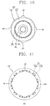
FIG. 10 is a side view of a stator ofFIG. 9 ; -
FIG. 11 is a side view of a frame ofFIG. 9 ; and -
FIG. 12 is a view for explaining a communicated status of a cooling path ofFIG. 11 . - Description will now be given in detail of the exemplary embodiments, with reference to the accompanying drawings. For the sake of brief description with reference to the drawings, the same or equivalent components will be provided with the same reference numbers, and description thereof will not be repeated.
- Hereinafter, preferred embodiments of the present invention will be explained in more details with reference to the attached drawings.
- As shown in
FIG. 1 , an electric vehicle having an electric motor according to an exemplary embodiment of the present invention may include avehicle body 10, abattery 25 provided in thevehicle body 10, and anelectric motor 105 provided in thevehicle body 10 and connected with thebattery 25 to provide driving force to thevehicle body 10. - Although not shown, a passenger space in which a passenger may get on (i.e., ride, board, embark, etc.) may be formed at an upper area of the
vehicle body 110. - A plurality of
wheels 15 allowing the vehicle to run may be provided at thevehicle body 10. - The
wheels 15 may be disposed on front and rear sides of thevehicle body 10. - A
suspension 20 may be provided between thevehicle body 10 and thewheels 15 in order to lessen vibration and an impact generated during running (or traveling). - The
battery 25 may be provided in thevehicle body 10 in order to supply power. - The
battery 25 may be configured as a rechargeable battery which can be recharged. - An
electric motor 105 may be provided in thevehicle body 10 in order to provide driving force to thewheels 15. - An
inverter device 30 may be provided between theelectric motor 105 and thebattery 25. - An
input cable 32 and anoutput cable 34 may be provided in theinverter device 30. For example, theinput cable 32 may be connected to thebattery 25, and the output cable 35 may be connected to theelectric motor 105. Accordingly, power provided from thebattery 25 may be converted to power required for driving theelectric motor 105 and provided to theelectric motor 105. - As shown in
FIGS. 2 to 5 , an electric motor according to one embodiment of the present invention comprises aframe 110, astator 130 disposed in theframe 110, arotor 150 disposed to be rotatable with respect to thestator 130, and anengaging portion 170 configured to restrict thestator 130 from moving with respect to theframe 110 in a circumferential direction, wherein theengaging portion 170 includes arib 171 protruding from one of contact surfaces between theframe 110 and thestator 130, and arib accommodation portion 173 formed at another of the contact surfaces so as to accommodate therib 171 therein so that heat can be transferred. - The
frame 110 may be configured to have an accommodation space therein. For instance, theframe 110 may be formed to have a cylindrical shape. And, theframe 110 may be formed such that both sides thereof are open. -
Covers 115 configured to block openings of theframe 110 may be provided at both ends of theframe 110. For instance, thecovers 115 may be detachably coupled to end portions of theframe 110. This may allow two end portions of theframe 110 to be open and closed. - Each
cover 115 may be provided with abearing 119. Thebearing 119 may be implemented as a radial bearing. - The
stator 130 may be provided in theframe 110. - The
stator 130 may include astator core 131 having a plurality ofteeth 135 and a plurality ofslots 136, and astator coil 141 wound on the plurality ofslots 136. Here, thestator coil 141 may be configured to be supplied with three-phase AC power. - A
rotor accommodation hole 134 configured to accommodate therotor 150 therein with a predetermined air gap may be provided at the center of thestator core 131. The plurality ofteeth 135 and theslots 136 may be formed at the periphery of therotor accommodation hole 134. Theteeth 135 and theslots 136 may be alternately formed in a circumferential direction. - The
stator core 131 may be formed by insulation-laminating a plurality ofelectrical steel sheets 132 with each other, the electrical steel sheets having therotor accommodation hole 134, theteeth 135 and theslots 136. - The
stator coil 141 may be wound on theslots 136. - After the
stator coil 141 has been wound on theslots 136, coil ends 142 of thestator coil 141 may be protruding from two end portions of thestator core 131 in an axial direction by a predetermined length. - The
rotor 150 may be implemented as an induction rotor having arotor core 151 and a plurality of conductingbars 155 inserted into therotor core 151. - A
rotation shaft 161 may be provided at the center of therotor core 151. Therotation shaft 161 may be rotatably supported by the bearing 119 provided at eachcover 115. - The
rotor core 151 may be formed by insulation-laminating a plurality ofelectrical steel sheets 152 with each other. - A
shaft hole 154 configured to insert therotation shaft 161 therein may be penetratingly formed at the center of eachelectrical steel sheet 152. - The plurality of conducting
bars 155 may be disposed to be spacing from each other in a circumferential direction of therotor core 151. - End rings 156 configured to connect the conducting bars 155 with each other so that the conducting
bars 155 can form a closed circuit (or closed loop) may be provided at two end portions of therotor core 151. - The
frame 110 may be provided with arib 171 protruding from an inner surface of theframe 110 toward a center and extending in an axial direction (axial direction of the rotor 150). Under this configuration, a surface area (inner surface) of theframe 110 may be increased. - The
rib 171 may be formed in plurality in number. - As shown in
FIG. 3 , the plurality ofribs 171 may be formed to be spacing from each other by a predetermined pitch in a circumferential direction of theframe 110. - The
rib 171 may be formed in correspondence to an entire length of theframe 110. More concretely, therib 171 may be formed to have a length equal to a length of theframe 110. Here, a size and the number of theribs 171 may be properly controlled. - The
stator 130 may be provided with a plurality ofrib accommodation portions 173 configured to accommodate theribs 171 of theframe 110 therein so that heat can be transferred. - The plurality of
rib accommodation portions 173 may be inwardly concaved from an outer surface of thestator core 131 in a radial direction. - Each
rib accommodation portion 173 may be configured to plane-contact an outer surface of eachrib 171. Under this configuration, a surface area of thestator 130 may be increased. More concretely, may be increased a heat exchange area (radiating area) of thestator 130, the area having a relatively higher temperature. - The
rib accommodation portions 173 are coupled to theribs 171 in a circumferential direction of theframe 110, thereby preventing thestator 130 from performing a relative motion with respect to the frame 110 (preventing thestator 130 from having a clearance) in a circumferential direction. This may prevent damages of the components due to a clearance of thestator 130, and enhance durability. - The
frame 110 may be provided with acooling path 175 through which a cooling fluid flows. This may cool theframe 110, and may rapidly cool thestator 130 contacting theframe 110 so that heat can be transferred. Since theframe 110 has an increased surface area (heat exchange area) by theribs 171, a heat exchange amount may be increased. - As shown in
FIG. 3 , thecooling path 175 may be formed at therib 171. Thecooling path 175 may be penetratingly formed at therib 171. Under this configuration, the cooling fluid flows at a position closer to thestator coil 141, a heating source for increasing an inner temperature of theframe 110. Accordingly, thestator 130 may be cooled more rapidly. That is, thecooling path 175 is disposed near thestator coil 141, a heating source, so that heat generated from thestator coil 141 is exchanged with the cooling fluid before spreading to the periphery. This may prevent increment of the peripheral temperature due to heat diffusion. - The cooling fluid may be configured to flow via the
covers 115. - Each
cover 115 may be provided with aninlet 116 for introducing the cooling fluid thereinto and anoutlet 117 for discharging the cooling fluid therefrom. - The
inlet 116 and theoutlet 117 may be formed on thesame cover 115, or may be separately formed atdifferent covers 115. Hereinafter, will be explained a case where theinlet 116 and theoutlet 117 are formed at theleft cover 115. - The
cooling path 175 may be provided withlinear section portions 176a formed at theribs 171 andcommunication portions 176b. Here, eachcommunication portion 176b is configured to communicate thelinear section portions 176a with each other. Although not shown, thecommunication portion 176b may be configured as a connection pipe. For instance, the connection pipe may be formed to have a 'U' shape, and may be configured to communicate thelinear section portions 176a with each other by being disposed at end sides of thelinear section portions 176a. - The
communication portion 176b may be formed at thecover 115. Under this configuration, may be cooled thecover 115 having an increased temperature due to increment of an inner temperature of theframe 110. - The
communication portion 176b may be concaved from an inner surface of eachcover 115 by a predetermined depth. - More concretely, the
communication portion 176b may be implemented in the form of a circular arc which connects thelinear section portions 176a of thecooling path 175 in a circumferential direction, thelinear section portions 176a formed at the tworibs 171 adjacent to each other. - As shown in
FIG. 6 , thecommunication portions 176b may be configured to communicate all the coolingpaths 175 formed at therespective ribs 171 with each other in a zigzag form. Under this configuration, thelinear section portions 176a and thecommunication portions 176b of the coolingpaths 175 may be integrally connected with each other, thereby forming one moving path for a cooling fluid. - The
cooling path 175 may be configured to have a plurality of moving paths for a cooling fluid by controlling thecommunication portion 176b. More concretely, thecooling path 175 may be configured to have a plurality ofinlets 116 andoutlets 117. Under this configuration, the cooling fluid may be exchanged with heat generated from theframe 110 more rapidly. This may allow theframe 110 to be cooled more rapidly. - A sealing
member 177 configured to prevent leakage of a cooling fluid may be provided at the periphery of thecooling path 175. - Meanwhile, the electric vehicle may include a cooling
fluid circulation unit 210 allowing the cooling fluid to circulate by way of the electric motor 1040. - As shown in
FIG. 7 , the coolingfluid circulation unit 210 may include afluid pipe 212 forming a flow path of the cooling fluid and a flow acceleration unit for accelerating the flow of the cooling fluid. The flow acceleration unit for accelerating the flow of the cooling fluid may be implemented as, for example, apump 214. - The cooling fluid may be configured to circulate by way of the
external case 141. - One side of the
fluid pipe 212 may be connected to communicate with the cooling fluid inlet unit 185 and the other side of thefluid pipe 212 may be coupled to communicate with the cooling fluid outlet unit 186. - The cooling
fluid circulation unit 210 may include atank 216 for temporarily storing the cooling fluid. - The
tank 216 may be disposed at the entrance (upper stream side) of thepump 214. - The cooling
fluid circulation unit 210 may include aradiator 217 allowing the cooling fluid to heat-exchange with air so as to be cooled therethrough. Accordingly, the cooling fluid at a temperature which has been increased while having passed through theelectric motor 140 can be cooled. - A cooling
fan 218 may be provided at one side of theradiator 217 may include a coolingfan 218 accelerating the flow of air in contact with theradiator 217. - The electric vehicle according to the present exemplary embodiment may include a
controller 220 having a control program. - As shown in
FIG. 8 , thecontroller 220 may be configured to detect the temperature of the cooling fluid to regulate a flow speed of the cooling fluid. - A
temperature detection unit 225 for detecting the temperature of the cooling fluid may be connected to thecontroller 220 in order to output a detection signal. Thetemperature detection unit 225 may output the detection temperature of the cooling fluid, as an electrical signal, to thecontroller 220. - The
pump 214 may be connected to thecontroller 220 such that it can be controlled by thecontroller 220. - Once a driving is started, power is supplied to the
stator coil 141. Then, a magnetic field (rotation magnetic field) may be formed at thestator coil 141. - Once a magnetic field is formed at the
stator coil 141, an induction current may be generated from therotor 150 by electromagnetic induction (EMI). - The
rotor 150 may rotate centering around therotation shaft 161 by an interaction (attractive force or repulsive force) with thestator 130. - Owing to the engaging
portion 170 having theribs 171 and therib accommodation portions 173, thestator 130 may be prevented from having a clearance from theframe 110 in a circumferential direction. This may prevent damages of the components due to a clearance of thestator 130 in a circumferential direction, and may prolong the lifespan of the electric motor. - Once power is supplied to the
stator coil 141 and therotor 150 starts to rotate, an inner temperature of theframe 110 may be increased due to copper loss, iron loss, mechanical loss, etc. - While the electric motor is driven, a cooling fluid may be supplied to the
cooling path 175. More concretely, the cooling fluid may be supplied to thecooling path 175 consecutively or after reaching a predetermined temperature. - The cooling fluid introduced into the
cooling path 175 through theinlet 116 may absorb peripheral heat while moving along thecooling path 175. This may rapidly lower an inner temperature of theframe 110. - The
frame 110 has an increased inner surface area by theribs 171, thereby rapidly absorbing peripheral heat. This may rapidly lower not only temperatures of theframe 110 and thestator 130, but also a temperature of an inner space of theframe 110. Accordingly, may be prevented lowering of an output density and efficiency of the electric motor due to temperature increment of the electric motor. As a result, may be implemented an electric motor for an electric vehicle having a high output density and high efficiency. - The cooling fluid having absorbed peripheral heat while moving along the
cooling path 175 may be discharged to the outside of thefame 110 through theoutlet 117. Then, the cooling fluid discharged to the outside of theframe 110 may be introduced into thecooling path 175 through theinlet 116. As these processes are repeatedly performed, a cooling operation for the electric motor may be continuously performed. - The electric motor may be provided with coolant cooling means (not shown) configured to cool the cooling fluid. The cooling fluid discharged to the outside of the
frame 110 is cooled by the coolant cooling means, and then is introduced into theframe 110 through theinlet 116. This may allow theframe 110 to be cooled more rapidly. - Hereinafter, another embodiment of the present invention will be explained with reference to
FIGS. 9 to 12 . - The same parts as those of the aforementioned embodiment will be provided with the same reference numerals, and detailed explanations thereof will be omitted for convenience.
- As shown in
FIGS. 9 to 11 , an electric motor according to another embodiment of the present invention comprises aframe 110, astator 130 disposed in theframe 110, arotor 150 disposed to be rotatable with respect to thestator 130, and an engagingportion 190 configured to restrict thestator 130 from moving with respect to theframe 110 in a circumferential direction, wherein the engagingportion 190 includes arib 191 protruding from one of contact surfaces between theframe 110 and thestator 130, and arib accommodation portion 193 formed at another of the contact surfaces so as to accommodate therib 191 therein so that heat can be transferred. - The
frame 110 may be formed in a cylindrical shape with an accommodation space therein. Here, both sides of the accommodation space are open. -
Covers 115 may be provided at both ends of theframe 110. - The
stator 130 may be provided in theframe 110, and therotor 150 may be disposed in thestator 130. Therotor 150 may be provided with arotation shaft 161. Thestator 130 and therotor 150 may be implemented as a three-phase induction electric motor. - The
stator 130 may include astator core 131 having arotor accommodation hole 134 therein, and astator coil 141 wound on thestator core 131. - The
rotor 150 may include arotor core 151 having a shaft hole at the center thereof, a plurality of conductingbars 155 provided at therotor core 151, and end rings 156. - As shown in
FIG. 10 , theribs 191 may be protruding from an outer surface of thestator 130 towards theframe 110. Under this configuration, an outer surface (surface area) of thestator 130 may be extended. Theribs 191 may accelerate a radiating operation of thestator 130. - More concretely, the
ribs 191 may be protruding from an outer surface of thestator core 131 in a radial direction, and may be extending in an axial direction. - The
ribs 191 may be formed in plurality in number. In this preferred embodiment, the number of theribs 191 is four. However, the number of theribs 191 is not limited to this, but may be properly controlled. - The
rib 191 may be formed to have a length equal to a lamination thickness (or a width in an axial direction) of thestator core 131. - As shown in
FIG. 11 , theframe 110 may be provided with a plurality ofrib accommodation portions 193 configured to accommodate therein theribs 191 of thestator 130. - Each
rib accommodation portion 193 may be configured to plane-contact eachrib 191. Under this configuration, heat generated from theribs 191 may be rapidly transferred to therib accommodation portions 193. - As the
ribs 191 and therib accommodation portions 193 are engaged with each other in a circumferential direction, a clearance of theframe 110 in a circumferential direction may be prevented. - Furthermore, as an inner surface (surface area) of the
frame 110 is extended by therib accommodation portions 193, a heat exchange area of theframe 110 with air inside theframe 110 may be increased. - The
frame 110 may be provided with coolingpaths 175 through which a cooling fluid flows. This may cool theframe 110, and may rapidly cool thestator 130 contacting theframe 110 so that heat can be transferred. - The cooling
paths 175 may be formed along therib accommodation portions 193. For instance, some of the coolingpaths 175 may be disposed to be adjacent to two sides of therib accommodation portions 193. Under this configuration, theribs 191 accommodated in therib accommodation portions 193 may be rapidly cooled. - The
cooling path 175 may includelinear section portions 176a, andcommunication portions 176b configured to communicate thelinear section portions 176a with each other. - The
communication portions 176b may be formed at thecover 115. - As shown in
FIG. 12 , each of thecommunication portions 176b may be configured to communicate two neighboringlinear section portions 176a with each other. Thecooling path 175 may be implemented as one moving path having oneinlet 116 and oneoutlet 117. Alternatively, thecooling path 175 may be implemented as a plurality of moving paths having a plurality ofinlets 116 and a plurality ofoutlets 117. - The
linear section portions 176a of thecooling path 175 may be disposed to be adjacent to two sides of therib accommodation portion 193. This may allow theribs 191 to be more rapidly cooled. - The
linear section portions 176a of thecooling path 175 may be disposed to be closer to therotation shaft 161 of therotor 150 than the end portion of therib 191 in a radial direction of therotor 150. Since thelinear section portions 176a of thecooling path 175 are more adjacent to thestator 130, thestator 130 may be cooled more rapidly. - Once the electric motor is driven, a magnetic field is formed at the
stator coil 141. And, therotor 150 may rotate centering around therotation shaft 161 by interworking with thestator 130. - The engaging
portion 190 prevents thestator 130 from relatively moving in a circumferential direction of theframe 110. This may prevent damages of the components due to a clearance of thestator 130 in a circumferential direction. Accordingly, the lifespan of the electric motor may be prolonged. - While the electric motor is driven, a cooling fluid may be supplied to the
cooling path 175. The cooling fluid introduced into thecooling path 175 through theinlet 116 may absorb peripheral heat while moving along thecooling path 175. - Since an outer surface (surface area) of the
stator 130 is extended by the plurality ofribs 191, thestator 130 may radiate heat more rapidly. This may allow thestator 130 to be cooled more rapidly. - Since an inner surface (heat absorbing area) of the
frame 110 is extended by the plurality ofrib accommodation portions 193, theframe 110 may absorb peripheral heat more rapidly. Accordingly, theframe 110 and thestator 130 may be cooled more rapidly. This may prevent lowering of an output density and efficiency due to a high temperature, and may implement an electric motor for an electric vehicle having a high output density and high efficiency. - The cooling fluid having absorbed peripheral heat while moving along the
cooling path 175 may be discharged to the outside of thefame 110 through theoutlet 117. Then, the cooling fluid discharged to the outside of theframe 110 may be introduced into thecooling path 175 through theinlet 116. As these processes are repeatedly performed, a cooling operation for the electric motor may be continuously performed. - The present invention may have the following advantages.
- Firstly, the engaging portion includes the rib protruding from one of contact surfaces between the frame and the stator, and the rib accommodation portion formed at another of the contact surfaces so as to accommodate the rib therein such that heat is transferred. This may increase a heat exchange area between the frame and the stator, thereby rapidly cooling the stator. This may prevent lowering of an output density and efficiency due to a high temperature, and may implement an electric motor for an electric vehicle having a high output density and high efficiency.
- Secondly, the rib is protruding in a radial direction, and is accommodated in the rib accommodation portion concaved in a radial direction. This may prevent the stator from moving with respect to the frame in a circumferential direction. As a result, an electric motor having enhanced durability may be implemented.
- Thirdly, the frame is provided with the ribs protruding from an inner surface of the frame in a radial direction and extending in an axial direction, and the cooling paths formed at the ribs. This may allow the cooling paths to be more adjacent to the stator. As a result, the stator may be cooled more rapidly.
- The foregoing embodiments and advantages are merely exemplary and are not to be construed as limiting the present disclosure. The present teachings can be readily applied to other types of apparatuses. This description is intended to be illustrative, and not to limit the scope of the claims. Many alternatives, modifications, and variations will be apparent to those skilled in the art. The features, structures, methods, and other characteristics of the exemplary embodiments described herein may be combined in various ways to obtain additional and/or alternative exemplary embodiments.
- As the present features may be embodied in several forms without departing from the characteristics thereof, it should also be understood that the above-described embodiments are not limited by any of the details of the foregoing description, unless otherwise specified, but rather should be construed broadly within its scope as defined in the appended claims, and therefore all changes and modifications that fall within the metes and bounds of the claims, or equivalents of such metes and bounds are therefore intended to be embraced by the appended claims.
Claims (11)
- An electric motor for an electric vehicle comprising:a frame;a stator disposed in the frame;a rotor disposed to be rotatable with respect to the stator; andan engaging portion that restricts the stator from moving with respect to the frame in a circumferential direction, the engaging portion including at least one rib protruding from one of the surfaces of the frame and the stator, and at least one rib accommodation portion formed at other of the surfaces of the frame and the stator, wherein the at least one rib and the at least one accommodation portion are engaged to allow heat to be transferred therebetween.
- The electric motor of claim 1, wherein a surface of the at least one rib makes contact with a surface of the at least one rib accommodation portion.
- The electric motor of claim 1 or 2, wherein the at least one rib comprises a plurality of ribs formed to be spaced from each other by a predetermined pitch at one of the surfaces of the frame and the stator.
- The electric motor of claim 1, 2 or 3, wherein the at least one rib accommodation portion comprises a plurality of rib accommodation portions formed to be spaced from each other by a predetermined pitch at one of the surfaces of the frame and the stator.
- The electric motor of any of claims 1 to 4, wherein at least one cooling path is formed at the frame.
- The electric motor of any of claims 1 to 5, further comprising a cooling path formed at the at least one rib of the frame.
- The electric motor of any of claims 1 to 6, further comprising a cooling path formed at the frame in a vicinity of the at least one rib accommodation portion.
- The electric motor of claim 5, wherein the at least one cooling path comprises a plurality of cooling paths, each cooling path penetrating the frame from one end surface to another end surface of the frame.
- The electric motor of claim 8, further comprising:at least two covers, one cover covering the one end surface of the frame and another cover covering the another end surface of the frame; andat least one communication portion formed at one of the at least two covers, wherein the at least one communication portion connects at least two of the cooling paths such that a zigzag fluid flow path is formed.
- The electric motor of claim 9, further comprising:at least one inlet in fluid communication with at least one of the cooling path; andat least one outlet in fluid communication with at least one of the cooling path.
- An electric vehicle comprising:a body;a plurality of wheels provided at the body;a battery provided in the body;an electric motor of any of claims 1 to 10, and the electric motor configured to drive at least one of the plurality of wheels; andan inverter coupled between the battery and the motor, the inverter including a plurality of elements to convert direct current (DC) power to alternating current (AC) power.
Applications Claiming Priority (1)
| Application Number | Priority Date | Filing Date | Title |
|---|---|---|---|
| KR1020100128669A KR101128128B1 (en) | 2010-12-15 | 2010-12-15 | Electric motor and electric vehicle having the same |
Publications (3)
| Publication Number | Publication Date |
|---|---|
| EP2466724A2 true EP2466724A2 (en) | 2012-06-20 |
| EP2466724A3 EP2466724A3 (en) | 2017-11-22 |
| EP2466724B1 EP2466724B1 (en) | 2020-03-18 |
Family
ID=45033873
Family Applications (1)
| Application Number | Title | Priority Date | Filing Date |
|---|---|---|---|
| EP11190779.6A Active EP2466724B1 (en) | 2010-12-15 | 2011-11-25 | Electric motor and electric vehicle having the same |
Country Status (3)
| Country | Link |
|---|---|
| US (1) | US8593020B2 (en) |
| EP (1) | EP2466724B1 (en) |
| KR (1) | KR101128128B1 (en) |
Families Citing this family (17)
| Publication number | Priority date | Publication date | Assignee | Title |
|---|---|---|---|---|
| JP5149431B2 (en) * | 2011-07-29 | 2013-02-20 | ファナック株式会社 | Temperature detection device that detects the temperature of the mover of the motor |
| JP6295726B2 (en) * | 2014-03-03 | 2018-03-20 | コベルコ建機株式会社 | Electric motor |
| WO2016196918A1 (en) | 2015-06-05 | 2016-12-08 | Ingersoll-Rand Company | Power tool user interfaces |
| US11260517B2 (en) | 2015-06-05 | 2022-03-01 | Ingersoll-Rand Industrial U.S., Inc. | Power tool housings |
| WO2016196984A1 (en) | 2015-06-05 | 2016-12-08 | Ingersoll-Rand Company | Power tools with user-selectable operational modes |
| US10668614B2 (en) | 2015-06-05 | 2020-06-02 | Ingersoll-Rand Industrial U.S., Inc. | Impact tools with ring gear alignment features |
| JP6915391B2 (en) * | 2016-08-30 | 2021-08-04 | 株式会社デンソー | Stator and its manufacturing method |
| US10476332B2 (en) * | 2016-12-21 | 2019-11-12 | Siemens Industry, Inc. | Rotor assembly and electrodynamic machine with axial vents for heat transfer |
| US10707718B2 (en) * | 2017-02-27 | 2020-07-07 | GM Global Technology Operations LLC | Electric motor stator assembly with captured retention feature |
| JP6542835B2 (en) * | 2017-05-30 | 2019-07-10 | ファナック株式会社 | Stator and rotating electric machine |
| KR20200125120A (en) | 2019-04-26 | 2020-11-04 | 주식회사 케이엠씨 | Method of manufacturing a rotor shaft for electric vehicle and rotor shaft itself |
| JP6830996B1 (en) * | 2019-12-26 | 2021-02-17 | 山洋電気株式会社 | Frame structure of synchronous motor and manufacturing method of frame and armature |
| CN211981596U (en) * | 2020-04-07 | 2020-11-20 | 精进电动科技股份有限公司 | A rotary stator positioning tablet and positioning structure |
| KR20220040265A (en) * | 2020-09-23 | 2022-03-30 | 현대모비스 주식회사 | Motor |
| JP7163948B2 (en) * | 2020-10-30 | 2022-11-01 | 株式会社富士通ゼネラル | compressor |
| DE102022101923A1 (en) * | 2022-01-27 | 2023-07-27 | Schaeffler Technologies AG & Co. KG | stator |
| CN220210077U (en) * | 2023-01-31 | 2023-12-19 | 日本电产株式会社 | Motor and electric product |
Family Cites Families (10)
| Publication number | Priority date | Publication date | Assignee | Title |
|---|---|---|---|---|
| KR19980015912U (en) * | 1996-09-13 | 1998-06-25 | 구자홍 | Stator assembly structure of motor |
| JP3468726B2 (en) * | 1999-09-01 | 2003-11-17 | 株式会社日立製作所 | Hybrid vehicles and rotating electric machines |
| JP3661589B2 (en) * | 2000-11-21 | 2005-06-15 | 日産自動車株式会社 | Motor or generator |
| DE102004007322A1 (en) * | 2004-02-14 | 2005-09-01 | Robert Bosch Gmbh | Stator arrangement for an electrical machine |
| JP4562093B2 (en) * | 2006-03-16 | 2010-10-13 | 三菱電機株式会社 | Rotating electric machine and method of manufacturing rotating electric machine |
| JP2008067571A (en) * | 2006-09-11 | 2008-03-21 | Jtekt Corp | Motor and electric pump |
| JP2009033884A (en) | 2007-07-27 | 2009-02-12 | Sumitomo Electric Ind Ltd | Stator and manufacturing method of stator |
| US8161643B2 (en) * | 2007-09-20 | 2012-04-24 | Arvinmeritor Technology, Llc | Method for forming a cooling jacket for an electric motor |
| JP5309987B2 (en) | 2008-12-27 | 2013-10-09 | シンフォニアテクノロジー株式会社 | Rotating electric machine |
| KR101116126B1 (en) * | 2009-12-29 | 2012-02-22 | 주식회사 효성 | Cooling structure for electric motor and method for manufacturing thereof |
-
2010
- 2010-12-15 KR KR1020100128669A patent/KR101128128B1/en active Active
-
2011
- 2011-09-14 US US13/232,236 patent/US8593020B2/en active Active
- 2011-11-25 EP EP11190779.6A patent/EP2466724B1/en active Active
Non-Patent Citations (1)
| Title |
|---|
| None |
Also Published As
| Publication number | Publication date |
|---|---|
| US20120153749A1 (en) | 2012-06-21 |
| US8593020B2 (en) | 2013-11-26 |
| EP2466724B1 (en) | 2020-03-18 |
| EP2466724A3 (en) | 2017-11-22 |
| KR101128128B1 (en) | 2012-03-22 |
Similar Documents
| Publication | Publication Date | Title |
|---|---|---|
| EP2466724B1 (en) | Electric motor and electric vehicle having the same | |
| EP2458717B1 (en) | Electric motor and electric vehicle having the same | |
| US8616315B2 (en) | Electric motor and electric vehicle having the same | |
| CN102197572B (en) | Dynamo-electric machine | |
| CN102341998B (en) | Electric motor comprising cooling channels | |
| US9966818B2 (en) | Water-cooled motor | |
| JP5625565B2 (en) | Rotating machine and vehicle | |
| US8922073B2 (en) | Electric motor and electric vehicle having the same | |
| KR20120121851A (en) | Electric motor and electric vechile having the same | |
| US8796895B2 (en) | Electric motor and electric vehicle having the same | |
| JP2009247085A (en) | Rotary electric machine | |
| CN101490931B (en) | cooling unit for motor | |
| JP2012223075A (en) | Cooling structure of rotary electric machine | |
| WO2018003214A1 (en) | Vehicle rotary electric machine | |
| KR101098841B1 (en) | Electric motor with composite cooling casing | |
| KR101176952B1 (en) | Electric motor and electric vehicle having the same | |
| JPWO2018179269A1 (en) | Electric motor for vehicle | |
| KR101412589B1 (en) | Electric motor and electric vehicle having the same | |
| KR20090073791A (en) | Electric motor chiller | |
| KR101454308B1 (en) | Cooling device for in-wheel motor of electric vehicle | |
| KR20120113612A (en) | Inverter apparatus and electric vehicle having the same | |
| KR20130005576A (en) | Stator for electric machine and electric motor having thereof, electric vechile having electric motor | |
| KR101412588B1 (en) | Electric motor and electric vechile having the same | |
| KR20260033327A (en) | complex cooling system for driving motor | |
| KR101432595B1 (en) | Stator for electric machine |
Legal Events
| Date | Code | Title | Description |
|---|---|---|---|
| PUAI | Public reference made under article 153(3) epc to a published international application that has entered the european phase |
Free format text: ORIGINAL CODE: 0009012 |
|
| 17P | Request for examination filed |
Effective date: 20111222 |
|
| AK | Designated contracting states |
Kind code of ref document: A2 Designated state(s): AL AT BE BG CH CY CZ DE DK EE ES FI FR GB GR HR HU IE IS IT LI LT LU LV MC MK MT NL NO PL PT RO RS SE SI SK SM TR |
|
| AX | Request for extension of the european patent |
Extension state: BA ME |
|
| PUAL | Search report despatched |
Free format text: ORIGINAL CODE: 0009013 |
|
| AK | Designated contracting states |
Kind code of ref document: A3 Designated state(s): AL AT BE BG CH CY CZ DE DK EE ES FI FR GB GR HR HU IE IS IT LI LT LU LV MC MK MT NL NO PL PT RO RS SE SI SK SM TR |
|
| AX | Request for extension of the european patent |
Extension state: BA ME |
|
| RIC1 | Information provided on ipc code assigned before grant |
Ipc: B60L 1/00 20060101ALI20171016BHEP Ipc: H02K 5/20 20060101ALI20171016BHEP Ipc: B60L 11/18 20060101ALI20171016BHEP Ipc: H02K 1/18 20060101AFI20171016BHEP Ipc: B60L 3/00 20060101ALI20171016BHEP |
|
| RBV | Designated contracting states (corrected) |
Designated state(s): AL AT BE BG CH CY CZ DE DK EE ES FI FR GB GR HR HU IE IS IT LI LT LU LV MC MK MT NL NO PL PT RO RS SE SI SK SM TR |
|
| REG | Reference to a national code |
Ref country code: DE Ref legal event code: R079 Ref document number: 602011065648 Country of ref document: DE Free format text: PREVIOUS MAIN CLASS: H02K0001180000 Ipc: B60L0050510000 |
|
| RIC1 | Information provided on ipc code assigned before grant |
Ipc: B60L 1/00 20060101ALI20191004BHEP Ipc: B60L 50/51 20190101AFI20191004BHEP Ipc: B60L 3/00 20190101ALI20191004BHEP Ipc: H02K 1/18 20060101ALI20191004BHEP Ipc: H02K 5/20 20060101ALI20191004BHEP |
|
| GRAP | Despatch of communication of intention to grant a patent |
Free format text: ORIGINAL CODE: EPIDOSNIGR1 |
|
| STAA | Information on the status of an ep patent application or granted ep patent |
Free format text: STATUS: GRANT OF PATENT IS INTENDED |
|
| INTG | Intention to grant announced |
Effective date: 20191125 |
|
| GRAS | Grant fee paid |
Free format text: ORIGINAL CODE: EPIDOSNIGR3 |
|
| GRAA | (expected) grant |
Free format text: ORIGINAL CODE: 0009210 |
|
| STAA | Information on the status of an ep patent application or granted ep patent |
Free format text: STATUS: THE PATENT HAS BEEN GRANTED |
|
| AK | Designated contracting states |
Kind code of ref document: B1 Designated state(s): AL AT BE BG CH CY CZ DE DK EE ES FI FR GB GR HR HU IE IS IT LI LT LU LV MC MK MT NL NO PL PT RO RS SE SI SK SM TR |
|
| RAP1 | Party data changed (applicant data changed or rights of an application transferred) |
Owner name: LG ELECTRONICS INC. |
|
| REG | Reference to a national code |
Ref country code: GB Ref legal event code: FG4D |
|
| REG | Reference to a national code |
Ref country code: DE Ref legal event code: R096 Ref document number: 602011065648 Country of ref document: DE |
|
| REG | Reference to a national code |
Ref country code: AT Ref legal event code: REF Ref document number: 1245530 Country of ref document: AT Kind code of ref document: T Effective date: 20200415 Ref country code: IE Ref legal event code: FG4D |
|
| PG25 | Lapsed in a contracting state [announced via postgrant information from national office to epo] |
Ref country code: RS Free format text: LAPSE BECAUSE OF FAILURE TO SUBMIT A TRANSLATION OF THE DESCRIPTION OR TO PAY THE FEE WITHIN THE PRESCRIBED TIME-LIMIT Effective date: 20200318 Ref country code: NO Free format text: LAPSE BECAUSE OF FAILURE TO SUBMIT A TRANSLATION OF THE DESCRIPTION OR TO PAY THE FEE WITHIN THE PRESCRIBED TIME-LIMIT Effective date: 20200618 Ref country code: FI Free format text: LAPSE BECAUSE OF FAILURE TO SUBMIT A TRANSLATION OF THE DESCRIPTION OR TO PAY THE FEE WITHIN THE PRESCRIBED TIME-LIMIT Effective date: 20200318 |
|
| REG | Reference to a national code |
Ref country code: NL Ref legal event code: MP Effective date: 20200318 |
|
| PG25 | Lapsed in a contracting state [announced via postgrant information from national office to epo] |
Ref country code: BG Free format text: LAPSE BECAUSE OF FAILURE TO SUBMIT A TRANSLATION OF THE DESCRIPTION OR TO PAY THE FEE WITHIN THE PRESCRIBED TIME-LIMIT Effective date: 20200618 Ref country code: LV Free format text: LAPSE BECAUSE OF FAILURE TO SUBMIT A TRANSLATION OF THE DESCRIPTION OR TO PAY THE FEE WITHIN THE PRESCRIBED TIME-LIMIT Effective date: 20200318 Ref country code: SE Free format text: LAPSE BECAUSE OF FAILURE TO SUBMIT A TRANSLATION OF THE DESCRIPTION OR TO PAY THE FEE WITHIN THE PRESCRIBED TIME-LIMIT Effective date: 20200318 Ref country code: GR Free format text: LAPSE BECAUSE OF FAILURE TO SUBMIT A TRANSLATION OF THE DESCRIPTION OR TO PAY THE FEE WITHIN THE PRESCRIBED TIME-LIMIT Effective date: 20200619 Ref country code: HR Free format text: LAPSE BECAUSE OF FAILURE TO SUBMIT A TRANSLATION OF THE DESCRIPTION OR TO PAY THE FEE WITHIN THE PRESCRIBED TIME-LIMIT Effective date: 20200318 |
|
| REG | Reference to a national code |
Ref country code: LT Ref legal event code: MG4D |
|
| PG25 | Lapsed in a contracting state [announced via postgrant information from national office to epo] |
Ref country code: NL Free format text: LAPSE BECAUSE OF FAILURE TO SUBMIT A TRANSLATION OF THE DESCRIPTION OR TO PAY THE FEE WITHIN THE PRESCRIBED TIME-LIMIT Effective date: 20200318 |
|
| PG25 | Lapsed in a contracting state [announced via postgrant information from national office to epo] |
Ref country code: LT Free format text: LAPSE BECAUSE OF FAILURE TO SUBMIT A TRANSLATION OF THE DESCRIPTION OR TO PAY THE FEE WITHIN THE PRESCRIBED TIME-LIMIT Effective date: 20200318 Ref country code: EE Free format text: LAPSE BECAUSE OF FAILURE TO SUBMIT A TRANSLATION OF THE DESCRIPTION OR TO PAY THE FEE WITHIN THE PRESCRIBED TIME-LIMIT Effective date: 20200318 Ref country code: SM Free format text: LAPSE BECAUSE OF FAILURE TO SUBMIT A TRANSLATION OF THE DESCRIPTION OR TO PAY THE FEE WITHIN THE PRESCRIBED TIME-LIMIT Effective date: 20200318 Ref country code: PT Free format text: LAPSE BECAUSE OF FAILURE TO SUBMIT A TRANSLATION OF THE DESCRIPTION OR TO PAY THE FEE WITHIN THE PRESCRIBED TIME-LIMIT Effective date: 20200812 Ref country code: SK Free format text: LAPSE BECAUSE OF FAILURE TO SUBMIT A TRANSLATION OF THE DESCRIPTION OR TO PAY THE FEE WITHIN THE PRESCRIBED TIME-LIMIT Effective date: 20200318 Ref country code: IS Free format text: LAPSE BECAUSE OF FAILURE TO SUBMIT A TRANSLATION OF THE DESCRIPTION OR TO PAY THE FEE WITHIN THE PRESCRIBED TIME-LIMIT Effective date: 20200718 Ref country code: RO Free format text: LAPSE BECAUSE OF FAILURE TO SUBMIT A TRANSLATION OF THE DESCRIPTION OR TO PAY THE FEE WITHIN THE PRESCRIBED TIME-LIMIT Effective date: 20200318 Ref country code: CZ Free format text: LAPSE BECAUSE OF FAILURE TO SUBMIT A TRANSLATION OF THE DESCRIPTION OR TO PAY THE FEE WITHIN THE PRESCRIBED TIME-LIMIT Effective date: 20200318 |
|
| REG | Reference to a national code |
Ref country code: AT Ref legal event code: MK05 Ref document number: 1245530 Country of ref document: AT Kind code of ref document: T Effective date: 20200318 |
|
| REG | Reference to a national code |
Ref country code: DE Ref legal event code: R097 Ref document number: 602011065648 Country of ref document: DE |
|
| PLBE | No opposition filed within time limit |
Free format text: ORIGINAL CODE: 0009261 |
|
| STAA | Information on the status of an ep patent application or granted ep patent |
Free format text: STATUS: NO OPPOSITION FILED WITHIN TIME LIMIT |
|
| PG25 | Lapsed in a contracting state [announced via postgrant information from national office to epo] |
Ref country code: AT Free format text: LAPSE BECAUSE OF FAILURE TO SUBMIT A TRANSLATION OF THE DESCRIPTION OR TO PAY THE FEE WITHIN THE PRESCRIBED TIME-LIMIT Effective date: 20200318 Ref country code: IT Free format text: LAPSE BECAUSE OF FAILURE TO SUBMIT A TRANSLATION OF THE DESCRIPTION OR TO PAY THE FEE WITHIN THE PRESCRIBED TIME-LIMIT Effective date: 20200318 Ref country code: DK Free format text: LAPSE BECAUSE OF FAILURE TO SUBMIT A TRANSLATION OF THE DESCRIPTION OR TO PAY THE FEE WITHIN THE PRESCRIBED TIME-LIMIT Effective date: 20200318 Ref country code: ES Free format text: LAPSE BECAUSE OF FAILURE TO SUBMIT A TRANSLATION OF THE DESCRIPTION OR TO PAY THE FEE WITHIN THE PRESCRIBED TIME-LIMIT Effective date: 20200318 |
|
| 26N | No opposition filed |
Effective date: 20201221 |
|
| PG25 | Lapsed in a contracting state [announced via postgrant information from national office to epo] |
Ref country code: PL Free format text: LAPSE BECAUSE OF FAILURE TO SUBMIT A TRANSLATION OF THE DESCRIPTION OR TO PAY THE FEE WITHIN THE PRESCRIBED TIME-LIMIT Effective date: 20200318 |
|
| PG25 | Lapsed in a contracting state [announced via postgrant information from national office to epo] |
Ref country code: SI Free format text: LAPSE BECAUSE OF FAILURE TO SUBMIT A TRANSLATION OF THE DESCRIPTION OR TO PAY THE FEE WITHIN THE PRESCRIBED TIME-LIMIT Effective date: 20200318 |
|
| PG25 | Lapsed in a contracting state [announced via postgrant information from national office to epo] |
Ref country code: MC Free format text: LAPSE BECAUSE OF FAILURE TO SUBMIT A TRANSLATION OF THE DESCRIPTION OR TO PAY THE FEE WITHIN THE PRESCRIBED TIME-LIMIT Effective date: 20200318 |
|
| REG | Reference to a national code |
Ref country code: CH Ref legal event code: PL |
|
| GBPC | Gb: european patent ceased through non-payment of renewal fee |
Effective date: 20201125 |
|
| PG25 | Lapsed in a contracting state [announced via postgrant information from national office to epo] |
Ref country code: LU Free format text: LAPSE BECAUSE OF NON-PAYMENT OF DUE FEES Effective date: 20201125 |
|
| REG | Reference to a national code |
Ref country code: BE Ref legal event code: MM Effective date: 20201130 |
|
| PG25 | Lapsed in a contracting state [announced via postgrant information from national office to epo] |
Ref country code: CH Free format text: LAPSE BECAUSE OF NON-PAYMENT OF DUE FEES Effective date: 20201130 Ref country code: LI Free format text: LAPSE BECAUSE OF NON-PAYMENT OF DUE FEES Effective date: 20201130 |
|
| PG25 | Lapsed in a contracting state [announced via postgrant information from national office to epo] |
Ref country code: FR Free format text: LAPSE BECAUSE OF NON-PAYMENT OF DUE FEES Effective date: 20201130 Ref country code: IE Free format text: LAPSE BECAUSE OF NON-PAYMENT OF DUE FEES Effective date: 20201125 |
|
| REG | Reference to a national code |
Ref country code: DE Ref legal event code: R081 Ref document number: 602011065648 Country of ref document: DE Owner name: LG MAGNA E-POWERTRAIN CO., LTD., KR Free format text: FORMER OWNER: LG ELECTRONICS INC., SEOUL, KR |
|
| PG25 | Lapsed in a contracting state [announced via postgrant information from national office to epo] |
Ref country code: GB Free format text: LAPSE BECAUSE OF NON-PAYMENT OF DUE FEES Effective date: 20201125 |
|
| PG25 | Lapsed in a contracting state [announced via postgrant information from national office to epo] |
Ref country code: TR Free format text: LAPSE BECAUSE OF FAILURE TO SUBMIT A TRANSLATION OF THE DESCRIPTION OR TO PAY THE FEE WITHIN THE PRESCRIBED TIME-LIMIT Effective date: 20200318 Ref country code: MT Free format text: LAPSE BECAUSE OF FAILURE TO SUBMIT A TRANSLATION OF THE DESCRIPTION OR TO PAY THE FEE WITHIN THE PRESCRIBED TIME-LIMIT Effective date: 20200318 Ref country code: CY Free format text: LAPSE BECAUSE OF FAILURE TO SUBMIT A TRANSLATION OF THE DESCRIPTION OR TO PAY THE FEE WITHIN THE PRESCRIBED TIME-LIMIT Effective date: 20200318 |
|
| PG25 | Lapsed in a contracting state [announced via postgrant information from national office to epo] |
Ref country code: MK Free format text: LAPSE BECAUSE OF FAILURE TO SUBMIT A TRANSLATION OF THE DESCRIPTION OR TO PAY THE FEE WITHIN THE PRESCRIBED TIME-LIMIT Effective date: 20200318 Ref country code: AL Free format text: LAPSE BECAUSE OF FAILURE TO SUBMIT A TRANSLATION OF THE DESCRIPTION OR TO PAY THE FEE WITHIN THE PRESCRIBED TIME-LIMIT Effective date: 20200318 |
|
| PG25 | Lapsed in a contracting state [announced via postgrant information from national office to epo] |
Ref country code: BE Free format text: LAPSE BECAUSE OF NON-PAYMENT OF DUE FEES Effective date: 20201130 |
|
| PG25 | Lapsed in a contracting state [announced via postgrant information from national office to epo] |
Ref country code: IS Free format text: LAPSE BECAUSE OF NON-PAYMENT OF DUE FEES Effective date: 20200718 |
|
| PGFP | Annual fee paid to national office [announced via postgrant information from national office to epo] |
Ref country code: DE Payment date: 20251002 Year of fee payment: 15 |