EP2466705A2 - Plasma jet ignition plug - Google Patents
Plasma jet ignition plug Download PDFInfo
- Publication number
- EP2466705A2 EP2466705A2 EP11193660A EP11193660A EP2466705A2 EP 2466705 A2 EP2466705 A2 EP 2466705A2 EP 11193660 A EP11193660 A EP 11193660A EP 11193660 A EP11193660 A EP 11193660A EP 2466705 A2 EP2466705 A2 EP 2466705A2
- Authority
- EP
- European Patent Office
- Prior art keywords
- insulator
- metallic shell
- center electrode
- plasma jet
- end surface
- Prior art date
- Legal status (The legal status is an assumption and is not a legal conclusion. Google has not performed a legal analysis and makes no representation as to the accuracy of the status listed.)
- Withdrawn
Links
Images

Classifications
-
- H—ELECTRICITY
- H01—ELECTRIC ELEMENTS
- H01T—SPARK GAPS; OVERVOLTAGE ARRESTERS USING SPARK GAPS; SPARKING PLUGS; CORONA DEVICES; GENERATING IONS TO BE INTRODUCED INTO NON-ENCLOSED GASES
- H01T13/00—Sparking plugs
- H01T13/50—Sparking plugs having means for ionisation of gap
-
- H—ELECTRICITY
- H01—ELECTRIC ELEMENTS
- H01T—SPARK GAPS; OVERVOLTAGE ARRESTERS USING SPARK GAPS; SPARKING PLUGS; CORONA DEVICES; GENERATING IONS TO BE INTRODUCED INTO NON-ENCLOSED GASES
- H01T13/00—Sparking plugs
- H01T13/02—Details
- H01T13/16—Means for dissipating heat
Definitions
- the present invention relates to a plasma jet ignition plug.
- a spark plug has been used to ignite an air-fuel mixture through spark discharge (may be referred to merely as "discharge") for operation of an engine, such as an automotive internal combustion engine.
- spark discharge may be referred to merely as "discharge"
- high output and low fuel consumption have been required of internal combustion engines.
- development of a plasma jet ignition plug has been conducted, since the plasma jet ignition plug provides quick propagation of combustion and exhibits such high ignition performance as to be capable of reliably igniting even a lean air-fuel mixture having a higher ignition-limit air-fuel ratio.
- the plasma jet ignition plug has a structure in which an insulator formed from ceramic or the like surrounds a spark discharge gap between a center electrode and a ground electrode, thereby forming a small-volume discharge space called a cavity.
- An example system of ignition of the plasma jet ignition plug is described.
- high voltage is applied between the center electrode and the ground electrode, thereby generating spark discharge.
- current can be applied between the center electrode and the ground electrode with a relatively low voltage.
- plasma is generated within the cavity.
- the generated plasma is jetted out through an opening (so-called orifice), thereby igniting the air-fuel mixture (refer to, for example, Patent Document 1).
- flame-like an example of the geometric shape of plasma jetted out from the opening is the form of a pillar of fire (hereinafter, such a form of plasma is referred to as "flame-like"). Because of extension in the direction of jet, the flame-like plasma is characterized by a large contact area with an air-fuel mixture and by high ignition performance.
- Patent Document 1 Japanese Patent Application Laid-Open ( kokai ) No. 2006-294257
- a plasma jet ignition plug having high plasma generation efficiency allows reduction in supplied energy while ensuring high ignition performance.
- An example method of improving plasma generation efficiency is to increase temperature within the cavity at the time of ignition.
- a conceivable method of increasing temperature within the cavity is to increase the temperature of the center electrode and the insulator at the time of ignition.
- an increase in the temperature of the insulator may involve the occurrence of preignition, a phenomenon that ignition takes place in advance of regular ignition timing with the insulator serving as a heat source.
- An object of the present invention is to provide a plasma jet ignition plug which exhibits high plasma generation efficiency while restraining the occurrence of preignition.
- a plasma jet ignition plug comprises a center electrode; an insulator having an axial bore extending in a direction of an axis and holding the center electrode within the axial bore; a metallic shell holding the insulator; and a ground electrode joined to the metallic shell and disposed frontward of the insulator.
- the insulator has an insulator ledge in direct or indirect contact with the center electrode for holding the center electrode.
- the center electrode has a taper portion in direct or indirect contact with the insulator ledge; a trunk portion located rearward of the taper portion with respect to the direction of the axis; and a front portion located frontward of the taper portion with respect to the direction of the axis.
- the metallic shell has a metallic shell ledge in direct or indirect contact with the insulator for holding the insulator.
- P1 represents a position of a rear end with respect to the direction of the axis of a region of the metallic shell ledge, the region being in direct or indirect contact with the insulator.
- P2 represents a position of a rear end with respect to the direction of the axis of a region of the insulator ledge, the region being in direct or indirect contact with the center electrode.
- a front end surface of the metallic shell, a front end surface of the insulator, a front end surface of the center electrode, an imaginary plane S1 which is perpendicular to the direction of the axis and which contains the position P1, and an imaginary plane S2 which is perpendicular to the direction of the axis and which contains the position P2 are disposed in this order from a front side to a rear side along the direction of the axis.
- An axial distance A from the front end surface of the insulator to the imaginary plane S1 and an axial distance B from the imaginary plane S1 to the imaginary plane S2 satisfy a relational expression 0.5 ⁇ A ⁇ B.
- the front end surface of the center electrode is disposed rearward of the front end surface of the insulator; thus, cooling of the center electrode associated with introduction of new air-fuel mixture into a combustion chamber can be prevented. Also, since the front end surface of the insulator is disposed rearward of the front end surface of the metallic shell, the outer circumferential surface of a front end portion of the insulator is unlikely to receive heat from combustion gas. Thus, an increase in temperature of the insulator can be prevented. Also, since the metallic shell ledge is disposed frontward of the taper portion of the center electrode, a heat transfer path of the insulator becomes shorter than a heat transfer path of the center electrode. As a result, the temperature of a front end portion of the insulator is likely to decrease, whereas the temperature of the center electrode is unlikely to decrease.
- the plasma jet ignition plug according to the present invention satisfies the relational expression 0.5 ⁇ A ⁇ B, preferably the relational expression A ⁇ B, heat transfer from the front end portion of the insulator is promoted, whereas heat transfer from the front end portion of the center electrode is reduced.
- a plasma jet ignition plug which exhibits high plasma generation efficiency while restraining the occurrence of preignition.
- the insulator can be prevented from receiving, from the metallic shell, heat which the metallic shell has received. Accordingly, the temperature of the front end portion of the insulator does not become excessively high, so that the occurrence of preignition can be restrained.
- the ground electrode has the contact portion, in contact with the front end surface of the insulator, formed at at least a portion of the facing surface of the ground electrode, the facing surface facing the front end surface of the insulator, heat of the front end portion of the insulator is released not only through the ledge of the metallic shell but also through the contact portion. Thus, the occurrence of preignition can be further restrained.
- combustion gas does not enter a space between the insulator and the ground electrode.
- an increase in temperature of the insulator caused by combustion gas can be prevented, so that the occurrence of preignition can be further restrained.
- FIG. 1 shows a plasma jet ignition plug according to an embodiment of the present invention.
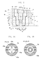
- FIG. 1 shows, partially in section, the configuration of a plasma jet ignition plug 1 according to the embodiment of the present invention.
- FIG. 2 shows, in section, essential portions of the plasma jet ignition plug 1.
- a downward direction on the paper on which FIG. 1 appears is referred to as a frontward direction along an axis O
- an upward direction on the paper is referred to as a rearward direction along the axis O.
- the plasma jet ignition plug 1 includes a substantially tubular insulator 4 having an axial bore 3 extending in the direction of the axis O, a center electrode 2 accommodated within the axial bore 3 of the insulator 4 on a front side, a metal terminal 20 whose portion is accommodated within the axial bore 3 of the insulator 4 on a rear side, a metallic shell 5 holding the insulator 4, and a ground electrode 6 joined to the metallic shell 5 and disposed frontward of the insulator 4.
- the insulator 4 is a substantially cylindrical insulation member formed from alumina or the like by firing and having the axial bore 3 along the direction of the axis O.
- the insulator 4 has a flange portion 7 having the largest outside diameter and formed substantially at its center with respect to the direction of the axis O.
- the insulator 4 has a rear trunk portion 8 extending rearward of the flange portion 7 and having an outside diameter smaller than that of the flange portion 7.
- the rear trunk portion 8 accommodates therein a portion of the metal terminal 20.
- the insulator 4 has a front trunk portion 9 extending frontward of the flange portion 7 and having an outside diameter smaller than that of the flange portion 7.
- the front trunk portion 9 accommodates therein a seal body 25 and a portion of the center electrode 2.
- the insulator 4 has an insulator front end portion 14 having an outside diameter smaller than that of the front trunk portion 9 and extending frontward of the front trunk portion 9 via an insulator taper portion 11 whose outside diameter reduces frontward from the front trunk portion 9.
- the insulator front end portion 14 accommodates therein the rest of the center electrode 2.
- the axial bore 3 of the insulator 4 extends frontward from the rear end of the insulator 4 as follows: the axial bore 3 extends through the rear trunk portion 8, the flange portion 7, and the front trunk portion 9 while having substantially the same inside diameter; the axial bore 3 extends through the front trunk portion 9 and reduces frontward in inside diameter so as to form an insulator ledge 15; and the axial bore 3 extends from the insulator ledge 15 through the insulator front end portion 14 while having a smaller inside diameter than in the front trunk portion 9.
- the insulator front end portion 14 has a second insulator ledge 17 located frontward of the insulator ledge 15 and formed with its inside diameter being further reduced frontward.
- the insulator front end portion 14 accommodates therein a forefront portion 23 of the center electrode 2 at a position located frontward of the second insulator ledge 17.
- the inner circumferential surface of the insulator front end portion 14, which accommodates therein the forefront portion 23, and a front end surface 40 of the forefront portion 23 define a discharge space called a cavity 50.
- the center electrode 2 is a substantially circular columnar electrode rod formed of a metal having excellent thermal conductivity, such as Ni or an Ni alloy.
- the center electrode 2 may internally have a metal core (not shown) formed of a metal higher in thermal conductivity than Ni, such as Cu.
- the center electrode 2 may have a disk-like electrode tip joined to its front end by welding or the like.
- the disk-like electrode tip is formed of an alloy which contains Ir, Pt, W, or Ni as a main component. Provision of the electrode tip is preferred because of enhancement of resistance to spark-induced erosion.
- the electrode tip has a thickness of at least 0.3 mm along the direction of the axis O.
- the "center electrode” encompasses the electrode tip formed integral with the center electrode 2.
- the center electrode 2 includes a taper portion 19 in direct or indirect contact with the insulator ledge 15, a trunk portion 13 located rearward of the taper portion 19, and a front portion 21 located frontward of the taper portion 19.
- the front portion 21 is smaller in outside diameter than the trunk portion 13.
- the center electrode 2 further includes the forefront portion 23 located frontward of the front portion 21 with a second taper portion 22 therebetween and being smaller in outside diameter than the front portion 21.
- the taper portion 19 of the center electrode 2 is in indirect contact with the insulator ledge 15 via a packing 24.
- the packing 24 is formed of a metal having high thermal conductivity, such as Cu or Fe.
- the taper portion 19 and the insulator ledge 15 may be in indirect contact with each other via plating on the insulator 4 or may be in direct contact with each other without another member intervening therebetween.
- the case where the taper portion 19 and the insulator ledge 15 are in indirect contact with each other excludes the case where air intervenes between the taper portion 19 and the insulator ledge 15.
- the center electrode 2 is electrically connected to the metal terminal 20 via an electrically conductive seal body 25 provided within the axial bore 3 and formed of a mixture of metal and glass.
- the center electrode 2 and the metal terminal 20 are fixed within the axial bore 3 and electrically communicate with each other by means of the seal body 25.
- the metal terminal 20 is connected to a high-voltage cable via a plug cap, whereby high voltage from a power supply is applied thereto (not shown).
- the metallic shell 5 is a substantially cylindrical metal member formed of an electrically conductive steel material; for example, low-carbon steel, and having a through hole 26 concentric with the axial bore 3.
- the metallic shell 5 is adapted to fix the plasma jet ignition plug 1 to the engine head of an internal combustion engine (not shown).
- the metallic shell 5 holds the insulator 4 in the through hole 26.
- the metallic shell 5 has a threaded portion 27 to be threadingly engaged with the engine head of the internal combustion engine.
- the metallic shell 5 has a seat portion 28 located rearward of the threaded portion 27 and formed on an outer circumferential surface thereof.
- a ringshaped gasket 47 is fitted to the metallic shell 5 between the rear end of the threaded portion 27 and the seat portion 28.
- the metallic shell 5 has a tool engagement portion 29 provided rearward of the seat portion 28 and allowing a tool, such as a plug wrench, to be fitted thereto when the metallic shell 5 is to be mounted to the engine head.
- the metallic shell 5 has a crimp portion 30 provided rearward of the tool engagement portion 29 and adapted to retain the insulator 4.
- Two ring members 31 and 32 are provided in an intervening manner in a space formed between the rear trunk portion 8 of the insulator 4 and a portion of the metallic shell 5 ranging from the tool engagement portion 29 to the crimp portion 30. Furthermore, a space between the two ring members 31 and 32 is filled with talc 33.
- the metallic shell 5 has a metallic shell ledge 34 which is located frontward of the seat portion 28 and in direct or indirect contact with the insulator 4 for holding the insulator 4.
- the metallic shell 5 has a metallic shell trunk portion 35 extending rearward of the metallic shell ledge 34, and a metallic shell front end portion 36 extending frontward of the metallic shell ledge 34.
- the metallic shell trunk portion 35 is larger in inside diameter than the metallic shell front end portion 36.
- the metallic shell ledge 34 of the metallic shell 5 is in indirect contact with the insulator taper portion 11 via a packing 37.
- the packing 37 is formed of a metal having high thermal conductivity, such as Cu or Fe.
- the metallic shell ledge 34 and the insulator taper portion 11 may be in direct contact with each other via plating on the insulator 4 and/or the metallic shell 5 or may be in direct contact with each other without another member intervening therebetween.
- the case where the metallic shell ledge 34 and the insulator taper portion 11 are in direct contact with each other excludes the case where air intervenes between the metallic shell ledge 34 and the insulator taper portion 11.
- the insulator 4 is united to the metallic shell 5. Gastightness between the metallic shell 5 and the insulator 4 is maintained by means of, for example, the packing 37, thereby preventing outflow of combustion gas.
- the present invention proposes a plasma jet ignition plug having a structure that can reduce heat transfer from the center electrode 2 for enhancing plasma generation efficiency by means of increasing temperature within the cavity 50 at the time of ignition, as well as a structure that avoids an excessive increase in temperature of the insulator 4 for restraining the occurrence of preignition while increasing temperature within the cavity 50.
- the plasma jet ignition plug of the present invention is configured as follows: when P1 represents the position of the rear end of a region of the metallic shell ledge 34, the region being in direct or indirect contact with the insulator 4, and P2 represents the position of the rear end of a region of the insulator ledge 15, the region being in direct or indirect contact with the center electrode 2, a front end surface 38 of the metallic shell 5, a front end surface 39 of the insulator 4, the front end surface 40 of the center electrode 2, an imaginary plane S1 which is perpendicular to the direction of the axis O and which contains the position P1, and an imaginary plane S2 which is perpendicular to the direction of the axis O and which contains the position P2 are disposed in this order from the front side to the rear side along the direction of the axis O. Also, the imaginary plane S1 is located rearward of the front end of the threaded portion 27.
- the insulator 4 serves as a wall.
- the center electrode 2 is unlikely to be affected by the air-fuel mixture of low temperature. Therefore, cooling of the center electrode 2 can be prevented.
- the front end surface 39 of the insulator 4 is disposed rearward of the front end surface 38 of the metallic shell 5, a front end portion outer circumferential surface 12 of the insulator 4 is unlikely to receive heat from combustion gas. Therefore, an increase in temperature of the insulator 4 can be prevented.
- an outer circumferential surface of the center electrode 2 between the front end and the taper portion 19 of the center electrode 2 and an inner circumferential surface of the insulator 4 between the front end and the insulator ledge 15 of the insulator 4 are virtually not in contact with each other. That is, there is no path of conduction of heat of the center electrode 2 to the insulator 4 between the outer circumferential surface of the center electrode 2 ranging from the front end of the center electrode 2 to the taper portion 19 of the center electrode 2 and the inner circumferential surface of the insulator 4 ranging from the front end of the insulator 4 to the insulator ledge 15.
- heat since there is no path of heat conduction at the forefront portion 23 and the front portion 21 of the center electrode 2, heat is unlikely to be released therefrom. Therefore, the temperature of the center electrode 2 is likely to be maintained.
- Heat of the forefront portion 23 and the front portion 21 of the center electrode 2 is conducted to the insulator 4 through a heat conduction path implemented by a region where the taper portion 19 of the center electrode 2 and the insulator ledge 15 are in contact with each other. Furthermore, heat of the insulator front end portion 14 is conducted to the metallic shell 5 through a heat conduction path implemented by a region where the insulator taper portion 11 and the metallic shell ledge 34 are in contact with each other. Also, heat of the metallic shell 5 is released to the ambient atmosphere through a heat conduction path implemented by a threaded hole portion of an internal combustion engine which is threadingly engaged with the threaded portion 27 of the metallic shell 5.
- the inventor of the present invention has conceived that the arrangement of the taper portion 19 of the center electrode 2, the insulator ledge 15, the insulator taper portion 11, and the metallic shell ledge 34, which form heat conduction paths, has a particularly large effect on heat transfer from the center electrode 2 and from the insulator 4.
- the taper portion 19 of the center electrode 2 is disposed rearward of the metallic shell ledge 34.
- Heat of the insulator front end portion 14 is conducted to the threaded portion 27 via the metallic shell ledge 34.
- heat of the forefront portion 23 and the front portion 21 of the center electrode 2 is conducted to the threaded portion 27 via the taper portion 19 disposed rearward of the metallic shell ledge 34 and further via the metallic shell ledge 34.
- the heat transfer path of the insulator 4 becomes shorter than the heat transfer path of the center electrode 2.
- heat transfer from the insulator front end portion 14 is accelerated, so that the temperature of the insulator 4 is likely to decrease.
- heat transfer from the center electrode 2 is reduced, so that the temperature of the center electrode 2 is unlikely to decrease.
- an axial distance A from the front end surface 39 of the insulator 4 to the imaginary plane S1 and an axial distance B from the imaginary plane S1 to the imaginary plane S2 satisfy the relational expression 0.5 ⁇ A ⁇ B, preferably A ⁇ B.
- a and B satisfy the relational expression 0.5 ⁇ A ⁇ B, the heat transfer path of the insulator 4 becomes short, and the heat transfer path of the center electrode 2 becomes relatively long.
- heat transfer from the front end portion of the insulator 4 is accelerated, whereas heat transfer from the forefront portion 23 and the front portion 21 of the center electrode 2 is reduced. Therefore, there can be provided a plasma jet ignition plug which exhibits high plasma generation efficiency while restraining the occurrence of preignition.
- an axial distance C from the front end surface 38 of the metallic shell 5 to the imaginary plane S1 satisfies the relational expression C ⁇ 3 mm.
- the insulator 4 can be prevented from receiving, from the metallic shell 5, heat which the metallic shell 5 has received. Accordingly, the temperature of the insulator front end portion 14 does not become excessively high, so that the occurrence of preignition can be restrained.
- the ground electrode 6 may be formed of a commonly known metal having excellent resistance against spark-induced erosion.
- the ground electrode 6 is formed of, for example, an alloy which contains W, Ir, Pt, or Ni as a main component.
- the ground electrode 6 exhibits excellent resistance to spark-induced erosion.
- the ground electrode 6 assumes the form of a disk and has an opening 41 at the center thereof, an increase in the diameter of the opening 41 can be restrained. Thus, a gap between the two electrodes is unlikely to increase, so that an increase in discharge voltage can be restrained as in the case of the center electrode 2.
- the ground electrode 6 has, for example, a disk-like shape having a thickness of 0.3 mm to 1 mm and has, at its center, the opening 41 for allowing the cavity 50 to communicate with the ambient atmosphere.
- the ground electrode 6 is integrally joined to the metallic shell 5 in the following manner: while the ground electrode 6 is engaged with an engagement portion 42 formed on an inner circumferential surface of the metallic shell front end portion 36 of the metallic shell 5 with a front end surface 43 of the ground electrode 6 and the front end surface 38 of the metallic shell 5 being flush with each other, the outer circumferential edge of the ground electrode 6 is, for example, full-circle laser-welded to the engagement portion 42.
- the inner circumferential surface of the opening 41 of the ground electrode 6 and a forefront portion inner circumferential surface 18 of the insulator 4 have the same diameter and are concentric with each other.
- the inside diameter of the opening 41 of the ground electrode 6 may be greater than that of the forefront portion inner circumferential surface 18.
- the ground electrode 6 has a contact portion 45, in contact with the front end surface 39 of the insulator 4, formed at a portion of a facing surface 44 of the ground electrode 6, the facing surface 44 facing the front end surface 39 of the insulator 4.
- FIGS. 3A and 3B are explanatory sectional views of plasma jet ignition plugs as cut by a plane which cross-sections the contact portion and is orthogonal to the axial direction, showing example shapes of contact portions 45a and 45b.
- the ground electrode may be a disk-like ground electrode which has an opening 41a and circular columnar contact portions 45a disposed at circumferentially equal intervals around the opening 41a; i.e., around an axial bore 3a.
- the ground electrode may be a disk-like ground electrode which has an opening 41b and an annular contact portion 45b formed continuously in such a manner as to encircle the opening 41b; i.e., an axial bore 3b.
- the annular contact portion 45b may be disposed such that its inner circumferential surface is flush with the insulator forefront portion inner circumferential surface 18.
- the contact portion 45b may have such a size that the contact portion 45b is in contact with a portion of the front end surface of an insulator 4b or in contact with the entire front end surface of the insulator 4b.
- the annular contact portion may have an inside diameter larger than that of an insulator forefront portion; i.e., the inner circumferential surface of the annular contact portion may be disposed closer to the metallic shell than is the inner circumferential surface of the insulator forefront portion which partially defines the cavity (not shown).
- the plasma jet ignition plug 1 having the above-mentioned structure generates plasma and ignites an air-fuel mixture, for example, in the following manner.
- high voltage is applied between the center electrode 2 and the ground electrode 6 to generate spark discharge.
- current can be applied between the center electrode 2 and the ground electrode 6 with relatively low voltage.
- current having a high energy of 30 mJ to 200 mJ is applied between the center electrode 2 and the ground electrode 6 from a power source having an arbitrary output for transition of a discharge state from spark discharge, thereby generating plasma within the cavity 50.
- the thus-generated plasma is discharged in a flame form from the opening 41 of the ground electrode 6, thereby igniting the air-fuel mixture.
- the plasma jet ignition plug 1 having the above-described structure can exhibit improved resistance to preignition by means of avoiding an excessive increase in the temperature of the insulator 4 and can maintain temperature within the cavity 50 by means of reducing heat transfer from the center electrode 2.
- a plasma jet ignition plug which exhibits high plasma generation efficiency while restraining the occurrence of preignition.
- the above-mentioned plasma jet ignition plug 1 is manufactured by a commonly known method.
- a well-known electrode material such as an Ni-based alloy, is machined for yielding the center electrode 2 having the taper portion 19 at a predetermined position.
- a disk-like electrode tip formed of material having excellent erosion resistance may be laser-welded to the front end surface of the center electrode 2.
- a well-known electrode material is machined into the ground electrode 6 having, for example, an annular form.
- the contact portion 45 is formed on one side of the annular ground electrode 6, so that, when the side of the ground electrode 6 is placed to face the front end surface 39 of the insulator 4, the contact portion 45 comes into contact with the front end surface 39.
- material for ceramic, or the like is formed into a predetermined shape, followed by firing for yielding the insulator 4 having the insulator ledge 15 and the insulator taper portion 11 at respectively predetermined positions.
- the center electrode 2 is assembled to the insulator 4 by a commonly known method so as to bring the taper portion 19 into contact with the insulator ledge 15.
- the outer circumferential surface of a tubular body formed of low-carbon steel or the like is subjected to machining, thereby forming the seat portion 28, the tool engagement portion 29, the threaded portion 27, etc., and also, the metallic shell ledge 34 is formed on the inner circumferential surface of the tubular body at a predetermined position, thereby yielding the metallic shell 5.
- the ground electrode 6 yielded above is joined to the engagement portion 42 formed on a front end portion inner circumferential surface 46 of the metallic shell 5 by, for example, laser welding or electric resistance welding.
- the insulator 4 to which the center electrode 2 is assembled is assembled to the metallic shell 5 to which the ground electrode 6 is joined, and the crimp portion 30 is crimped.
- the insulator 4 is pressed frontward within the metallic shell 5, whereby the insulator taper portion 11 is supported by the metallic shell ledge 34; thus, the metallic shell 5 and the insulator 4 are united together. In this manner, the plasma jet ignition plug 1 is manufactured.
- the plasma jet ignition plug according to the present invention is used as an igniter for an automotive internal combustion engine; for example, a gasoline engine.
- the plasma jet ignition plug is fixed at a predetermined position such that the threaded portion 27 is threadingly engaged with a threaded hole provided in a head (not shown) which dividingly forms combustion chambers of an internal combustion engine.
- the plasma jet ignition plug according to the present invention can be used in any type of internal combustion engine, but can be particularly preferably used in an internal combustion engine having high air-fuel ratio, since the plasma jet ignition plug can exhibit high ignition performance through supply of minimal energy while restraining the occurrence of preignition.
- the plasma jet ignition plug 1 according to the present invention is not limited to the embodiment described above, but may be modified in various other forms, so long as the object of the present invention can be achieved.
- a plasma generation efficiency evaluation test was conducted on plasma jet ignition plugs which differed in the axial distance A, the axial distance B, and the inside diameter of a front end portion of the axial bore of the insulator (cavity diameter).
- the plasma jet ignition plugs similar to the plasma jet ignition plug shown in FIG. 1 were manufactured under the following conditions: the difference (A - D) between the axial distance A and the axial distance D is 1 mm; the disk-like ground electrode having a thickness (C - A) of 0.5 mm and having, at its center, an opening of the same diameter as the cavity diameter is joined to the inner circumferential surface of a front end portion of the metallic shell; and the facing surface of the ground electrode which faces the front end surface of the insulator is in contact with the front end surface of the insulator continuously around the axial bore.
- the manufactured plasma jet ignition plugs were mounted to the chamber which was filled with standard gas at a pressure of 0.4 MPa. Energy of 50 mJ was supplied to the plasma jet ignition plugs for generating discharge.
- the plasma jet ignition plugs which generated discharge were evaluated for plasma generation efficiency by means of measuring the flame area of discharged plasma by use of the schlieren visualization method.
- a schlieren image was captured 100 ⁇ s after trigger ignition.
- the captured image was binarized.
- the area of a black zone in the binarized image was measured as the area of a high-density portion of plasma flame.
- FIGS. 4 and 5 show the results of the measurement.
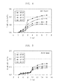
- FIG. 4 shows the results of the evaluation test on the plasma jet ignition plugs having an axial distance A of 3 mm.
- the horizontal axis indicates the axial distance B.
- the vertical axis indicates the ratio of the flame area measured with the axial distance B being varied in a range of 1 mm to 7 mm to the flame area measured with an axial distance B of 1 mm. Also, while the cavity diameter was varied at 0.5 mm intervals from 0.5 mm to 2.0 mm, the flame area was measured at individual cavity diameters, and the flame area ratio was calculated.
- FIG. 5 shows the results of the evaluation test on the plasma jet ignition plugs having an axial distance A of 10 mm. Similar to the evaluation test on the plasma jet ignition plugs having an axial distance A of 3 mm shown in FIG. 4 , the ratio of the flame area measured with the axial distance B being varied in a range of 4 mm to 16 mm to the flame area measured with an axial distance B of 4 mm was calculated.
- the flame area ratio increased when B ⁇ 5 mm, and further increased when B ⁇ 10 mm. This indicates that, when A and B satisfy the relational expression 0.5 ⁇ A ⁇ B, particularly A ⁇ B, the plasma generation efficiency improves. Also, the smaller the cavity diameter, the greater the flame area; i.e., the higher the plasma generation efficiency.
- the plasma jet ignition plugs similar to the plasma jet ignition plug shown in FIG. 1 were manufactured under the following conditions: the cavity diameter is 1.0 mm; the difference (A - D) between the axial distance A and the axial distance D is 1.0 mm; the disk-like ground electrode having a thickness (C - A) of 0.5 mm and having, at its center, an opening of the same diameter as the cavity diameter is joined to the inner circumferential surface of a front end portion of the metallic shell; and the facing surface of the ground electrode which faces the front end surface of the insulator is in contact with the front end surface of the insulator continuously around the axial bore.
- the manufactured plasma jet ignition plugs were mounted to a single-cylinder 125 cc engine.
- the engine was operated at an engine speed of 9,000 rpm with full throttle opening until preignition occurred.
- measurement was made for one minute under evaluation conditions (as indicated by the vertical axis of FIG. 6 , at intervals of a crank angle of 0.5°).
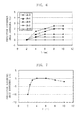
- FIG. 6 shows the results of measurement.
- the horizontal axis indicates B
- the vertical axis indicates a preignition occurrence crank angle difference when B was varied at 2 mm intervals from 2 mm to 10 mm, and a preignition occurrence crank angle at a B value of 2 mm was used as a reference angle.
- A was varied in a range of 3 mm to 10 mm, and associated preignition occurrence crank angles were measured, whereby corresponding preignition occurrence crank angle differences were calculated.
- a negative value is on the lag side, indicating deterioration in resistance to preignition.
- a positive value is on the lead side, indicating improvement in resistance to preignition.
- the greater the value of B the greater the preignition angle difference, indicating improvement in resistance to preignition.
- the smaller the value of A the higher the effect of improving resistance to preignition.
- A is 10 mm, even though the value of B increases, the effect of improving resistance to preignition is not observed, and deterioration in resistance to preignition is not observed, either.
- the horizontal axis indicates C
- the vertical axis indicates a preignition occurrence crank angle difference when C was varied at 2 mm intervals from 2 mm to 10 mm, and a preignition occurrence crank angle at a C value of 4 mm was used as a reference angle.
Abstract
Description
- The present invention relates to a plasma jet ignition plug.
- Conventionally, a spark plug has been used to ignite an air-fuel mixture through spark discharge (may be referred to merely as "discharge") for operation of an engine, such as an automotive internal combustion engine. In recent years, high output and low fuel consumption have been required of internal combustion engines. To fulfill such requirements, development of a plasma jet ignition plug has been conducted, since the plasma jet ignition plug provides quick propagation of combustion and exhibits such high ignition performance as to be capable of reliably igniting even a lean air-fuel mixture having a higher ignition-limit air-fuel ratio.
- The plasma jet ignition plug has a structure in which an insulator formed from ceramic or the like surrounds a spark discharge gap between a center electrode and a ground electrode, thereby forming a small-volume discharge space called a cavity. An example system of ignition of the plasma jet ignition plug is described. For ignition of an air-fuel mixture, first, high voltage is applied between the center electrode and the ground electrode, thereby generating spark discharge. By virtue of associated occurrence of dielectric breakdown, current can be applied between the center electrode and the ground electrode with a relatively low voltage. Thus, through transition of a discharge state from the spark discharge effected by further supply of energy, plasma is generated within the cavity. The generated plasma is jetted out through an opening (so-called orifice), thereby igniting the air-fuel mixture (refer to, for example, Patent Document 1).
- Meanwhile, an example of the geometric shape of plasma jetted out from the opening is the form of a pillar of fire (hereinafter, such a form of plasma is referred to as "flame-like"). Because of extension in the direction of jet, the flame-like plasma is characterized by a large contact area with an air-fuel mixture and by high ignition performance.
- Patent Document 1: Japanese Patent Application Laid-Open (kokai) No.
2006-294257 - However, in order to jet out flame-like plasma, high-energy current must be supplied to the plasma jet ignition plug. Supply of high-energy current causes intensive erosion of the center and ground electrodes and a like problem, potentially resulting in deterioration in durability of the plasma jet ignition plug. Thus, it is desirable that high ignition performance can be ensured by means of flame-like plasma being jetted out through supply of minimal-energy current. A plasma jet ignition plug having high plasma generation efficiency allows reduction in supplied energy while ensuring high ignition performance. An example method of improving plasma generation efficiency is to increase temperature within the cavity at the time of ignition. A conceivable method of increasing temperature within the cavity is to increase the temperature of the center electrode and the insulator at the time of ignition. However, an increase in the temperature of the insulator may involve the occurrence of preignition, a phenomenon that ignition takes place in advance of regular ignition timing with the insulator serving as a heat source.
- An object of the present invention is to provide a plasma jet ignition plug which exhibits high plasma generation efficiency while restraining the occurrence of preignition.
- To achieve the above-mentioned object, the present invention provides a plasma jet ignition plug described below in (1). (1) A plasma jet ignition plug comprises a center electrode; an insulator having an axial bore extending in a direction of an axis and holding the center electrode within the axial bore; a metallic shell holding the insulator; and a ground electrode joined to the metallic shell and disposed frontward of the insulator. The insulator has an insulator ledge in direct or indirect contact with the center electrode for holding the center electrode. The center electrode has a taper portion in direct or indirect contact with the insulator ledge; a trunk portion located rearward of the taper portion with respect to the direction of the axis; and a front portion located frontward of the taper portion with respect to the direction of the axis. The metallic shell has a metallic shell ledge in direct or indirect contact with the insulator for holding the insulator. P1 represents a position of a rear end with respect to the direction of the axis of a region of the metallic shell ledge, the region being in direct or indirect contact with the insulator. P2 represents a position of a rear end with respect to the direction of the axis of a region of the insulator ledge, the region being in direct or indirect contact with the center electrode. A front end surface of the metallic shell, a front end surface of the insulator, a front end surface of the center electrode, an imaginary plane S1 which is perpendicular to the direction of the axis and which contains the position P1, and an imaginary plane S2 which is perpendicular to the direction of the axis and which contains the position P2 are disposed in this order from a front side to a rear side along the direction of the axis. An axial distance A from the front end surface of the insulator to the imaginary plane S1 and an axial distance B from the imaginary plane S1 to the imaginary plane S2 satisfy a relational expression 0.5 × A ≤ B.
- In the plasma jet ignition plug described above in (1), preferably,
- (2) the axial distance A and the axial distance B satisfy a relation expression A ≤ B,
- (3) an axial distance C from the front end surface of the metallic shell to the imaginary plane S1 satisfies a relational expression C ≥ 3 mm,
- (4) the
ground electrode 6 has a contact portion, in contact with the front end surface of the insulator, formed at at least a portion of a facing surface of the ground electrode, the facing surface facing the front end surface of the insulator, and - (5) the contact portion is formed continuously in such a manner as to encircle the axial bore.
- In the plasma jet ignition plug according to the present invention, the front end surface of the center electrode is disposed rearward of the front end surface of the insulator; thus, cooling of the center electrode associated with introduction of new air-fuel mixture into a combustion chamber can be prevented. Also, since the front end surface of the insulator is disposed rearward of the front end surface of the metallic shell, the outer circumferential surface of a front end portion of the insulator is unlikely to receive heat from combustion gas. Thus, an increase in temperature of the insulator can be prevented. Also, since the metallic shell ledge is disposed frontward of the taper portion of the center electrode, a heat transfer path of the insulator becomes shorter than a heat transfer path of the center electrode. As a result, the temperature of a front end portion of the insulator is likely to decrease, whereas the temperature of the center electrode is unlikely to decrease.
- Furthermore, since the plasma jet ignition plug according to the present invention satisfies the relational expression 0.5 × A ≤ B, preferably the relational expression A ≤ B, heat transfer from the front end portion of the insulator is promoted, whereas heat transfer from the front end portion of the center electrode is reduced. Thus, there can be provided a plasma jet ignition plug which exhibits high plasma generation efficiency while restraining the occurrence of preignition.
- Also, by means of the axial distance C satisfying the relational expression C ≥ 3 mm, the insulator can be prevented from receiving, from the metallic shell, heat which the metallic shell has received. Accordingly, the temperature of the front end portion of the insulator does not become excessively high, so that the occurrence of preignition can be restrained.
- When the ground electrode has the contact portion, in contact with the front end surface of the insulator, formed at at least a portion of the facing surface of the ground electrode, the facing surface facing the front end surface of the insulator, heat of the front end portion of the insulator is released not only through the ledge of the metallic shell but also through the contact portion. Thus, the occurrence of preignition can be further restrained.
- Furthermore, when the contact portion is formed continuously in such a manner as to encircle the axial bore, combustion gas does not enter a space between the insulator and the ground electrode. Thus, an increase in temperature of the insulator caused by combustion gas can be prevented, so that the occurrence of preignition can be further restrained.
-
-
FIG. 1 is an explanatory, partially sectional view showing the configuration of a plasma jet ignition plug according to an embodiment of the present invention. -
FIG. 2 is an explanatory sectional view showing essential portions of the plasma jet ignition plug ofFIG. 1 . -
FIG. 3A is an explanatory sectional view of a plasma jet ignition plug as cut by a plane which cross-sections contact portions and is orthogonal to the axial direction. -
FIG. 3B is an explanatory sectional view of a plasma jet ignition plug as cut by a plane which cross-sections a contact portion and is orthogonal to the axial direction. -
FIG. 4 is a graph showing the results of an evaluation test on plasma jet ignition plugs having an axial distance A of 3 mm. -
FIG. 5 is a graph showing the results of an evaluation test on plasma jet ignition plugs having an axial distance A of 10 mm. -
FIG. 6 is a graph showing the results of a resistance to preignition evaluation test. - [
FIG. 7 ] Graph showing the results of the resistance to preignition evaluation test. -
FIG. 1 shows a plasma jet ignition plug according to an embodiment of the present invention.FIG. 1 shows, partially in section, the configuration of a plasmajet ignition plug 1 according to the embodiment of the present invention.FIG. 2 shows, in section, essential portions of the plasmajet ignition plug 1. In the following description with reference toFIGS. 1 and2 , a downward direction on the paper on whichFIG. 1 appears is referred to as a frontward direction along an axis O, and an upward direction on the paper is referred to as a rearward direction along the axis O. - As shown in
FIGS. 1 and2 , the plasmajet ignition plug 1 includes a substantiallytubular insulator 4 having anaxial bore 3 extending in the direction of the axis O, acenter electrode 2 accommodated within theaxial bore 3 of theinsulator 4 on a front side, ametal terminal 20 whose portion is accommodated within theaxial bore 3 of theinsulator 4 on a rear side, ametallic shell 5 holding theinsulator 4, and aground electrode 6 joined to themetallic shell 5 and disposed frontward of theinsulator 4. - The
insulator 4 is a substantially cylindrical insulation member formed from alumina or the like by firing and having theaxial bore 3 along the direction of the axis O. Theinsulator 4 has aflange portion 7 having the largest outside diameter and formed substantially at its center with respect to the direction of the axis O. Theinsulator 4 has arear trunk portion 8 extending rearward of theflange portion 7 and having an outside diameter smaller than that of theflange portion 7. Therear trunk portion 8 accommodates therein a portion of themetal terminal 20. Theinsulator 4 has afront trunk portion 9 extending frontward of theflange portion 7 and having an outside diameter smaller than that of theflange portion 7. Thefront trunk portion 9 accommodates therein aseal body 25 and a portion of thecenter electrode 2. Furthermore, theinsulator 4 has an insulatorfront end portion 14 having an outside diameter smaller than that of thefront trunk portion 9 and extending frontward of thefront trunk portion 9 via aninsulator taper portion 11 whose outside diameter reduces frontward from thefront trunk portion 9. The insulatorfront end portion 14 accommodates therein the rest of thecenter electrode 2. Theaxial bore 3 of theinsulator 4 extends frontward from the rear end of theinsulator 4 as follows: theaxial bore 3 extends through therear trunk portion 8, theflange portion 7, and thefront trunk portion 9 while having substantially the same inside diameter; theaxial bore 3 extends through thefront trunk portion 9 and reduces frontward in inside diameter so as to form an insulator ledge 15; and theaxial bore 3 extends from the insulator ledge 15 through the insulatorfront end portion 14 while having a smaller inside diameter than in thefront trunk portion 9. The insulatorfront end portion 14 has asecond insulator ledge 17 located frontward of the insulator ledge 15 and formed with its inside diameter being further reduced frontward. The insulatorfront end portion 14 accommodates therein aforefront portion 23 of thecenter electrode 2 at a position located frontward of thesecond insulator ledge 17. The inner circumferential surface of the insulatorfront end portion 14, which accommodates therein theforefront portion 23, and a front end surface 40 of theforefront portion 23 define a discharge space called acavity 50. - The
center electrode 2 is a substantially circular columnar electrode rod formed of a metal having excellent thermal conductivity, such as Ni or an Ni alloy. Thecenter electrode 2 may internally have a metal core (not shown) formed of a metal higher in thermal conductivity than Ni, such as Cu. Also, thecenter electrode 2 may have a disk-like electrode tip joined to its front end by welding or the like. The disk-like electrode tip is formed of an alloy which contains Ir, Pt, W, or Ni as a main component. Provision of the electrode tip is preferred because of enhancement of resistance to spark-induced erosion. Preferably, the electrode tip has a thickness of at least 0.3 mm along the direction of the axis O. Through employment of a thickness of at least 0.3 mm, sufficient durability can be attained, so that a gap between the two electrodes is unlikely to increase over a long period of use. Eventually, an increase in discharge voltage required for generation of sparks can be maintained at low level. Also, the thickness is sufficient for welding the electrode tip to the center electrode base metal. In the present embodiment, the "center electrode" encompasses the electrode tip formed integral with thecenter electrode 2. - The
center electrode 2 includes a taper portion 19 in direct or indirect contact with the insulator ledge 15, atrunk portion 13 located rearward of the taper portion 19, and afront portion 21 located frontward of the taper portion 19. Thefront portion 21 is smaller in outside diameter than thetrunk portion 13. In the present embodiment, thecenter electrode 2 further includes theforefront portion 23 located frontward of thefront portion 21 with asecond taper portion 22 therebetween and being smaller in outside diameter than thefront portion 21. - In the present embodiment, the taper portion 19 of the
center electrode 2 is in indirect contact with the insulator ledge 15 via a packing 24. The packing 24 is formed of a metal having high thermal conductivity, such as Cu or Fe. The taper portion 19 and the insulator ledge 15 may be in indirect contact with each other via plating on theinsulator 4 or may be in direct contact with each other without another member intervening therebetween. The case where the taper portion 19 and the insulator ledge 15 are in indirect contact with each other excludes the case where air intervenes between the taper portion 19 and the insulator ledge 15. - The
center electrode 2 is electrically connected to themetal terminal 20 via an electricallyconductive seal body 25 provided within theaxial bore 3 and formed of a mixture of metal and glass. Thecenter electrode 2 and themetal terminal 20 are fixed within theaxial bore 3 and electrically communicate with each other by means of theseal body 25. Themetal terminal 20 is connected to a high-voltage cable via a plug cap, whereby high voltage from a power supply is applied thereto (not shown). - The
metallic shell 5 is a substantially cylindrical metal member formed of an electrically conductive steel material; for example, low-carbon steel, and having a throughhole 26 concentric with theaxial bore 3. Themetallic shell 5 is adapted to fix the plasmajet ignition plug 1 to the engine head of an internal combustion engine (not shown). Themetallic shell 5 holds theinsulator 4 in the throughhole 26. Themetallic shell 5 has a threadedportion 27 to be threadingly engaged with the engine head of the internal combustion engine. Themetallic shell 5 has aseat portion 28 located rearward of the threadedportion 27 and formed on an outer circumferential surface thereof. Aringshaped gasket 47 is fitted to themetallic shell 5 between the rear end of the threadedportion 27 and theseat portion 28. Furthermore, themetallic shell 5 has atool engagement portion 29 provided rearward of theseat portion 28 and allowing a tool, such as a plug wrench, to be fitted thereto when themetallic shell 5 is to be mounted to the engine head. Themetallic shell 5 has acrimp portion 30 provided rearward of thetool engagement portion 29 and adapted to retain theinsulator 4. Tworing members rear trunk portion 8 of theinsulator 4 and a portion of themetallic shell 5 ranging from thetool engagement portion 29 to thecrimp portion 30. Furthermore, a space between the tworing members talc 33. - In the through
hole 26 of themetallic shell 5, themetallic shell 5 has ametallic shell ledge 34 which is located frontward of theseat portion 28 and in direct or indirect contact with theinsulator 4 for holding theinsulator 4. Themetallic shell 5 has a metallicshell trunk portion 35 extending rearward of themetallic shell ledge 34, and a metallic shellfront end portion 36 extending frontward of themetallic shell ledge 34. The metallicshell trunk portion 35 is larger in inside diameter than the metallic shellfront end portion 36. - In the present embodiment, the
metallic shell ledge 34 of themetallic shell 5 is in indirect contact with theinsulator taper portion 11 via a packing 37. The packing 37 is formed of a metal having high thermal conductivity, such as Cu or Fe. Themetallic shell ledge 34 and theinsulator taper portion 11 may be in direct contact with each other via plating on theinsulator 4 and/or themetallic shell 5 or may be in direct contact with each other without another member intervening therebetween. The case where themetallic shell ledge 34 and theinsulator taper portion 11 are in direct contact with each other excludes the case where air intervenes between themetallic shell ledge 34 and theinsulator taper portion 11. - By means of the
insulator taper portion 11 being supported by themetallic shell ledge 34, theinsulator 4 is united to themetallic shell 5. Gastightness between themetallic shell 5 and theinsulator 4 is maintained by means of, for example, the packing 37, thereby preventing outflow of combustion gas. - The present invention proposes a plasma jet ignition plug having a structure that can reduce heat transfer from the
center electrode 2 for enhancing plasma generation efficiency by means of increasing temperature within thecavity 50 at the time of ignition, as well as a structure that avoids an excessive increase in temperature of theinsulator 4 for restraining the occurrence of preignition while increasing temperature within thecavity 50. - As shown in
FIG. 2 , the plasma jet ignition plug of the present invention is configured as follows: when P1 represents the position of the rear end of a region of themetallic shell ledge 34, the region being in direct or indirect contact with theinsulator 4, and P2 represents the position of the rear end of a region of the insulator ledge 15, the region being in direct or indirect contact with thecenter electrode 2, afront end surface 38 of themetallic shell 5, afront end surface 39 of theinsulator 4, the front end surface 40 of thecenter electrode 2, an imaginary plane S1 which is perpendicular to the direction of the axis O and which contains the position P1, and an imaginary plane S2 which is perpendicular to the direction of the axis O and which contains the position P2 are disposed in this order from the front side to the rear side along the direction of the axis O. Also, the imaginary plane S1 is located rearward of the front end of the threadedportion 27. - According to the plasma jet ignition plug of the present invention, since the front end surface 40 of the
center electrode 2 is disposed rearward of thefront end surface 39 of theinsulator 4, theinsulator 4 serves as a wall. Thus, even though a new air-fuel mixture is introduced into a combustion chamber, thecenter electrode 2 is unlikely to be affected by the air-fuel mixture of low temperature. Therefore, cooling of thecenter electrode 2 can be prevented. Also, according to the plasma jet ignition plug of the present invention, since thefront end surface 39 of theinsulator 4 is disposed rearward of thefront end surface 38 of themetallic shell 5, a front end portion outercircumferential surface 12 of theinsulator 4 is unlikely to receive heat from combustion gas. Therefore, an increase in temperature of theinsulator 4 can be prevented. - Also, an outer circumferential surface of the
center electrode 2 between the front end and the taper portion 19 of thecenter electrode 2 and an inner circumferential surface of theinsulator 4 between the front end and the insulator ledge 15 of theinsulator 4 are virtually not in contact with each other. That is, there is no path of conduction of heat of thecenter electrode 2 to theinsulator 4 between the outer circumferential surface of thecenter electrode 2 ranging from the front end of thecenter electrode 2 to the taper portion 19 of thecenter electrode 2 and the inner circumferential surface of theinsulator 4 ranging from the front end of theinsulator 4 to the insulator ledge 15. Thus, since there is no path of heat conduction at theforefront portion 23 and thefront portion 21 of thecenter electrode 2, heat is unlikely to be released therefrom. Therefore, the temperature of thecenter electrode 2 is likely to be maintained. - Heat of the
forefront portion 23 and thefront portion 21 of thecenter electrode 2 is conducted to theinsulator 4 through a heat conduction path implemented by a region where the taper portion 19 of thecenter electrode 2 and the insulator ledge 15 are in contact with each other. Furthermore, heat of the insulatorfront end portion 14 is conducted to themetallic shell 5 through a heat conduction path implemented by a region where theinsulator taper portion 11 and themetallic shell ledge 34 are in contact with each other. Also, heat of themetallic shell 5 is released to the ambient atmosphere through a heat conduction path implemented by a threaded hole portion of an internal combustion engine which is threadingly engaged with the threadedportion 27 of themetallic shell 5. Thus, the inventor of the present invention has conceived that the arrangement of the taper portion 19 of thecenter electrode 2, the insulator ledge 15, theinsulator taper portion 11, and themetallic shell ledge 34, which form heat conduction paths, has a particularly large effect on heat transfer from thecenter electrode 2 and from theinsulator 4. - According to the plasma jet ignition plug of the present invention, the taper portion 19 of the
center electrode 2 is disposed rearward of themetallic shell ledge 34. Heat of the insulatorfront end portion 14 is conducted to the threadedportion 27 via themetallic shell ledge 34. Meanwhile, heat of theforefront portion 23 and thefront portion 21 of thecenter electrode 2 is conducted to the threadedportion 27 via the taper portion 19 disposed rearward of themetallic shell ledge 34 and further via themetallic shell ledge 34. Thus, the heat transfer path of theinsulator 4 becomes shorter than the heat transfer path of thecenter electrode 2. As a result, heat transfer from the insulatorfront end portion 14 is accelerated, so that the temperature of theinsulator 4 is likely to decrease. By contrast, heat transfer from thecenter electrode 2 is reduced, so that the temperature of thecenter electrode 2 is unlikely to decrease. - According to the plasma jet ignition plug of the present invention, an axial distance A from the
front end surface 39 of theinsulator 4 to the imaginary plane S1 and an axial distance B from the imaginary plane S1 to the imaginary plane S2 satisfy the relational expression 0.5 × A ≤ B, preferably A ≤ B. When A and B satisfy the relational expression 0.5 × A ≤ B, the heat transfer path of theinsulator 4 becomes short, and the heat transfer path of thecenter electrode 2 becomes relatively long. Thus, heat transfer from the front end portion of theinsulator 4 is accelerated, whereas heat transfer from theforefront portion 23 and thefront portion 21 of thecenter electrode 2 is reduced. Therefore, there can be provided a plasma jet ignition plug which exhibits high plasma generation efficiency while restraining the occurrence of preignition. - According to the plasma jet ignition plug of the present invention, an axial distance C from the
front end surface 38 of themetallic shell 5 to the imaginary plane S1 satisfies the relational expression C ≥ 3 mm. When the axial distance C satisfies the relational expression C ≥ 3 mm, theinsulator 4 can be prevented from receiving, from themetallic shell 5, heat which themetallic shell 5 has received. Accordingly, the temperature of the insulatorfront end portion 14 does not become excessively high, so that the occurrence of preignition can be restrained. - The
ground electrode 6 may be formed of a commonly known metal having excellent resistance against spark-induced erosion. Preferably, theground electrode 6 is formed of, for example, an alloy which contains W, Ir, Pt, or Ni as a main component. When theground electrode 6 is formed of the alloy, theground electrode 6 exhibits excellent resistance to spark-induced erosion. In the case where theground electrode 6 assumes the form of a disk and has anopening 41 at the center thereof, an increase in the diameter of theopening 41 can be restrained. Thus, a gap between the two electrodes is unlikely to increase, so that an increase in discharge voltage can be restrained as in the case of thecenter electrode 2. Theground electrode 6 has, for example, a disk-like shape having a thickness of 0.3 mm to 1 mm and has, at its center, theopening 41 for allowing thecavity 50 to communicate with the ambient atmosphere. In the present embodiment, theground electrode 6 is integrally joined to themetallic shell 5 in the following manner: while theground electrode 6 is engaged with anengagement portion 42 formed on an inner circumferential surface of the metallic shellfront end portion 36 of themetallic shell 5 with a front end surface 43 of theground electrode 6 and thefront end surface 38 of themetallic shell 5 being flush with each other, the outer circumferential edge of theground electrode 6 is, for example, full-circle laser-welded to theengagement portion 42. In the present embodiment, the inner circumferential surface of theopening 41 of theground electrode 6 and a forefront portion innercircumferential surface 18 of theinsulator 4 have the same diameter and are concentric with each other. However, the inside diameter of theopening 41 of theground electrode 6 may be greater than that of the forefront portion innercircumferential surface 18. - Also, in the present embodiment, the
ground electrode 6 has a contact portion 45, in contact with thefront end surface 39 of theinsulator 4, formed at a portion of a facingsurface 44 of theground electrode 6, the facingsurface 44 facing thefront end surface 39 of theinsulator 4.FIGS. 3A and 3B are explanatory sectional views of plasma jet ignition plugs as cut by a plane which cross-sections the contact portion and is orthogonal to the axial direction, showing example shapes ofcontact portions FIG. 3A , the ground electrode may be a disk-like ground electrode which has anopening 41a and circularcolumnar contact portions 45a disposed at circumferentially equal intervals around theopening 41a; i.e., around anaxial bore 3a. Also, as shown inFIG. 3B , the ground electrode may be a disk-like ground electrode which has anopening 41b and anannular contact portion 45b formed continuously in such a manner as to encircle theopening 41b; i.e., anaxial bore 3b. Theannular contact portion 45b may be disposed such that its inner circumferential surface is flush with the insulator forefront portion innercircumferential surface 18. In this case, thecontact portion 45b may have such a size that thecontact portion 45b is in contact with a portion of the front end surface of an insulator 4b or in contact with the entire front end surface of the insulator 4b. Also, the annular contact portion may have an inside diameter larger than that of an insulator forefront portion; i.e., the inner circumferential surface of the annular contact portion may be disposed closer to the metallic shell than is the inner circumferential surface of the insulator forefront portion which partially defines the cavity (not shown). - When the
ground electrode 6 has the contact portion 45, heat of the insulatorfront end portion 14 is released not only through themetallic shell ledge 34 but also through the contact portion 45. Thus, the occurrence of preignition can be further restrained. Furthermore, when the contact portion 45 is formed continuously in such a manner as to encircle theaxial bore 3, combustion gas does not enter a space between theinsulator 4 and theground electrode 6. Thus, an increase in temperature of theinsulator 4 which could otherwise be caused by combustion gas can be prevented, so that the occurrence of preignition can be further restrained. - The plasma
jet ignition plug 1 having the above-mentioned structure generates plasma and ignites an air-fuel mixture, for example, in the following manner. In igniting the air-fuel mixture, first, high voltage is applied between thecenter electrode 2 and theground electrode 6 to generate spark discharge. By virtue of associated occurrence of dielectric breakdown, current can be applied between thecenter electrode 2 and theground electrode 6 with relatively low voltage. Further, current having a high energy of 30 mJ to 200 mJ is applied between thecenter electrode 2 and theground electrode 6 from a power source having an arbitrary output for transition of a discharge state from spark discharge, thereby generating plasma within thecavity 50. The thus-generated plasma is discharged in a flame form from theopening 41 of theground electrode 6, thereby igniting the air-fuel mixture. - The plasma
jet ignition plug 1 having the above-described structure can exhibit improved resistance to preignition by means of avoiding an excessive increase in the temperature of theinsulator 4 and can maintain temperature within thecavity 50 by means of reducing heat transfer from thecenter electrode 2. Thus, there can be provided a plasma jet ignition plug which exhibits high plasma generation efficiency while restraining the occurrence of preignition. - The above-mentioned plasma
jet ignition plug 1 is manufactured by a commonly known method. First, a well-known electrode material, such as an Ni-based alloy, is machined for yielding thecenter electrode 2 having the taper portion 19 at a predetermined position. At this time, as mentioned above, a disk-like electrode tip formed of material having excellent erosion resistance may be laser-welded to the front end surface of thecenter electrode 2. In a separate step, a well-known electrode material is machined into theground electrode 6 having, for example, an annular form. Preferably, the contact portion 45 is formed on one side of theannular ground electrode 6, so that, when the side of theground electrode 6 is placed to face thefront end surface 39 of theinsulator 4, the contact portion 45 comes into contact with thefront end surface 39. - Next, material for ceramic, or the like is formed into a predetermined shape, followed by firing for yielding the
insulator 4 having the insulator ledge 15 and theinsulator taper portion 11 at respectively predetermined positions. Thecenter electrode 2 is assembled to theinsulator 4 by a commonly known method so as to bring the taper portion 19 into contact with the insulator ledge 15. - The outer circumferential surface of a tubular body formed of low-carbon steel or the like is subjected to machining, thereby forming the
seat portion 28, thetool engagement portion 29, the threadedportion 27, etc., and also, themetallic shell ledge 34 is formed on the inner circumferential surface of the tubular body at a predetermined position, thereby yielding themetallic shell 5. Next, theground electrode 6 yielded above is joined to theengagement portion 42 formed on a front end portion innercircumferential surface 46 of themetallic shell 5 by, for example, laser welding or electric resistance welding. - The
insulator 4 to which thecenter electrode 2 is assembled is assembled to themetallic shell 5 to which theground electrode 6 is joined, and thecrimp portion 30 is crimped. By this procedure, theinsulator 4 is pressed frontward within themetallic shell 5, whereby theinsulator taper portion 11 is supported by themetallic shell ledge 34; thus, themetallic shell 5 and theinsulator 4 are united together. In this manner, the plasmajet ignition plug 1 is manufactured. - The plasma jet ignition plug according to the present invention is used as an igniter for an automotive internal combustion engine; for example, a gasoline engine. The plasma jet ignition plug is fixed at a predetermined position such that the threaded
portion 27 is threadingly engaged with a threaded hole provided in a head (not shown) which dividingly forms combustion chambers of an internal combustion engine. The plasma jet ignition plug according to the present invention can be used in any type of internal combustion engine, but can be particularly preferably used in an internal combustion engine having high air-fuel ratio, since the plasma jet ignition plug can exhibit high ignition performance through supply of minimal energy while restraining the occurrence of preignition. - The plasma
jet ignition plug 1 according to the present invention is not limited to the embodiment described above, but may be modified in various other forms, so long as the object of the present invention can be achieved. - A plasma generation efficiency evaluation test was conducted on plasma jet ignition plugs which differed in the axial distance A, the axial distance B, and the inside diameter of a front end portion of the axial bore of the insulator (cavity diameter).
- For use in the evaluation test as test samples, the plasma jet ignition plugs similar to the plasma jet ignition plug shown in
FIG. 1 were manufactured under the following conditions: the difference (A - D) between the axial distance A and the axial distance D is 1 mm; the disk-like ground electrode having a thickness (C - A) of 0.5 mm and having, at its center, an opening of the same diameter as the cavity diameter is joined to the inner circumferential surface of a front end portion of the metallic shell; and the facing surface of the ground electrode which faces the front end surface of the insulator is in contact with the front end surface of the insulator continuously around the axial bore. - The manufactured plasma jet ignition plugs were mounted to the chamber which was filled with standard gas at a pressure of 0.4 MPa. Energy of 50 mJ was supplied to the plasma jet ignition plugs for generating discharge.
- The plasma jet ignition plugs which generated discharge were evaluated for plasma generation efficiency by means of measuring the flame area of discharged plasma by use of the schlieren visualization method. A schlieren image was captured 100 µs after trigger ignition. The captured image was binarized. The area of a black zone in the binarized image was measured as the area of a high-density portion of plasma flame.
FIGS. 4 and 5 show the results of the measurement. -
FIG. 4 shows the results of the evaluation test on the plasma jet ignition plugs having an axial distance A of 3 mm. The horizontal axis indicates the axial distance B. The vertical axis indicates the ratio of the flame area measured with the axial distance B being varied in a range of 1 mm to 7 mm to the flame area measured with an axial distance B of 1 mm. Also, while the cavity diameter was varied at 0.5 mm intervals from 0.5 mm to 2.0 mm, the flame area was measured at individual cavity diameters, and the flame area ratio was calculated. - In the case of an axial distance A of 3 mm, the flame area ratio increased when B 1.5 mm, and further increased when B ≥ 3 mm. This indicates that, when A and B satisfy the relational expression 0.5 × A ≤ B, particularly A ≤ B, the plasma generation efficiency improves. Also, the smaller the cavity diameter, the greater the flame area; i.e., the higher the effect of improving the plasma generation efficiency.
-
FIG. 5 shows the results of the evaluation test on the plasma jet ignition plugs having an axial distance A of 10 mm. Similar to the evaluation test on the plasma jet ignition plugs having an axial distance A of 3 mm shown inFIG. 4 , the ratio of the flame area measured with the axial distance B being varied in a range of 4 mm to 16 mm to the flame area measured with an axial distance B of 4 mm was calculated. - In the case of an axial distance A of 10 mm, the flame area ratio increased when B ≥ 5 mm, and further increased when B ≥ 10 mm. This indicates that, when A and B satisfy the relational expression 0.5 × A ≤ B, particularly A ≤ B, the plasma generation efficiency improves. Also, the smaller the cavity diameter, the greater the flame area; i.e., the higher the plasma generation efficiency.
-
- (1) A resistance to preignition evaluation test was conducted on plasma jet ignition plugs which differed in the axial distance A and the axial distance B.
- For use in the evaluation test as test samples, the plasma jet ignition plugs similar to the plasma jet ignition plug shown in
FIG. 1 were manufactured under the following conditions: the cavity diameter is 1.0 mm; the difference (A - D) between the axial distance A and the axial distance D is 1.0 mm; the disk-like ground electrode having a thickness (C - A) of 0.5 mm and having, at its center, an opening of the same diameter as the cavity diameter is joined to the inner circumferential surface of a front end portion of the metallic shell; and the facing surface of the ground electrode which faces the front end surface of the insulator is in contact with the front end surface of the insulator continuously around the axial bore. - The manufactured plasma jet ignition plugs were mounted to a single-cylinder 125 cc engine. The engine was operated at an engine speed of 9,000 rpm with full throttle opening until preignition occurred. During the operation, measurement was made for one minute under evaluation conditions (as indicated by the vertical axis of
FIG. 6 , at intervals of a crank angle of 0.5°). - In order to evaluate resistance to preignition of the manufactured plasma jet ignition plugs, a crank angle at which preignition occurred was measured as ignition timing at which preignition occurred once or more in one minute.
FIG. 6 shows the results of measurement. - In
FIG. 6 , the horizontal axis indicates B, and the vertical axis indicates a preignition occurrence crank angle difference when B was varied at 2 mm intervals from 2 mm to 10 mm, and a preignition occurrence crank angle at a B value of 2 mm was used as a reference angle. Also, A was varied in a range of 3 mm to 10 mm, and associated preignition occurrence crank angles were measured, whereby corresponding preignition occurrence crank angle differences were calculated. A negative value is on the lag side, indicating deterioration in resistance to preignition. A positive value is on the lead side, indicating improvement in resistance to preignition. - As shown in
FIG. 6 , the greater the value of B, the greater the preignition angle difference, indicating improvement in resistance to preignition. Also, the smaller the value of A, the higher the effect of improving resistance to preignition. When A is 10 mm, even though the value of B increases, the effect of improving resistance to preignition is not observed, and deterioration in resistance to preignition is not observed, either. - When the value of A is small, the axial length of a front end portion of the center electrode is small. Thus, the smaller the value of B, the greater the amount of heat conducted from the center electrode to the insulator; accordingly, heat transfer from the insulator is greatly affected. Therefore, conceivably, when the value of A was small, the greater the value of B, the more the resistance to preignition improved. Meanwhile, when the value of A is large, the axial length of the front end portion of the center electrode is large. Thus, the amount of heat conducted from the center electrode to the insulator is small irrespective of the value of B; accordingly, heat transfer from the insulator becomes less affected. Therefore, conceivably, the greater the value of A, the more the influence of the value of B on resistance to preignition reduced.
-
- (2) The resistance to preignition evaluation test was conducted on plasma jet ignition plugs which differed in the axial distance C from the front end surface of the metallic shell to the imaginary plane S1, in a manner similar to that of the evaluation test described above in (1).
- In
FIG. 7 , the horizontal axis indicates C, and the vertical axis indicates a preignition occurrence crank angle difference when C was varied at 2 mm intervals from 2 mm to 10 mm, and a preignition occurrence crank angle at a C value of 4 mm was used as a reference angle. - As shown in
FIG. 7 , when the value of C reduces to less than 3 mm, the preignition occurrence crank angle difference sharply reduces, indicating deterioration in resistance to preignition. -
- 1: plasma jet ignition plug
- 2: center electrode
- 3: axial bore
- 4: insulator
- 5: metallic shell
- 6: ground electrode
- 7: flange portion
- 8: rear trunk portion
- 9: front portion
- 10: insulator trunk portion outer circumferential surface
- 11: insulator taper portion
- 12: front end portion outer circumferential surface of insulator
- 13: trunk portion
- 14: insulator front end portion
- 15: insulator ledge
- 17: second insulator ledge
- 18: forefront portion inner circumferential surface of insulator
- 19: taper portion
- 20: metal terminal
- 21: front end portion
- 22: second taper portion
- 23: forefront portion
- 24, 37: packing
- 25: seal body
- 26: through hole
- 27: threaded portion
- 28: seat portion
- 29: tool engagement portion
- 30: crimp portion
- 31, 32: ring member
- 33: talc
- 34: metallic shell ledge
- 35: metallic shell trunk portion
- 36: metallic shell front end portion
- 38: front end surface of metallic shell
- 39: front end surface of insulator
- 40: front end surface of center electrode
- 41: opening
- 42: engagement portion
- 43: front end surface of ground electrode
- 44: facing surface
- 45: contact portion
- 46: front end portion inner circumferential surface of metallic shell
- 47: gasket
- 50: cavity
Claims (5)
- A plasma jet ignition plug comprising:a center electrode (2);an insulator (4) having an axial bore (3, 3a, or 3b) extending in a direction of an axis (O) and holding the center electrode (2) within the axial bore (3, 3a, or 3b);a metallic shell (5, 5a, or 5b) holding the insulator (4); anda ground electrode (6) joined to the metallic shell (5, 5a, or 5b) and disposed frontward of the insulator (4);wherein the insulator (4) has an insulator ledge (15) in direct or indirect contact with the center electrode (2) for holding the center electrode (2);
the center electrode (2) has a taper portion (19(in direct or indirect contact with the insulator ledge (15), a trunk portion (13) located rearward of the taper portion (19) with respect to the direction of the axis (O), and a front portion (21) located frontward of the taper portion (19) with respect to the direction of the axis (O);
the metallic shell (5, 5a, or 5b) has a metallic shell ledge (34) in direct or indirect contact with the insulator (4) for holding the insulator (4);
a front end surface (38) of the metallic shell (5, 5a, or 5b), a front end surface (39) of the insulator (4), a front end surface (40) of the center electrode (2), an imaginary plane S1 which is perpendicular to the direction of the axis (O) and which contains a position P1, and an imaginary plane S2 which is perpendicular to the direction of the axis and which contains a position P2 are disposed in this order from a front side to a rear side along the direction of the axis (O),
where the position P1 represents a position of a rear end with respect to the direction of the axis (O) of a region of the metallic shell ledge (34), the region being in direct or indirect contact with the insulator (4),
where the position P2 represents a position of a rear end with respect to the direction of the axis (O) of a region of the insulator ledge (15), the region being in direct or indirect contact with the center electrode (2); and
an axial distance A from the front end surface (39) of the insulator (4) to the imaginary plane S1 and an axial distance B from the imaginary plane S1 to the imaginary plane S2 satisfy a relational expression 0.5 × A ≤ B. - A plasma jet ignition plug according to claim 1, wherein the axial distance A and the axial distance B satisfy a relation expression A ≤ B.
- A plasma jet ignition plug according to claim 1 or 2, wherein the front end surface (38) of the metallic shell (5, 5a, or 5b) and the imaginary plane S1 are located an axial distance C away from each other, and the axial distance C satisfies a relational expression C ≥ 3 mm.
- A plasma jet ignition plug according to any one of claims 1 or 3, wherein the ground electrode (6) has a contact portion (45, 45a, or 45b), in contact with the front end surface (39) of the insulator (4), formed at least at a portion of a facing surface (44) of the ground electrode (6), the facing surface (44) facing the front end surface (39) of the insulator.
- A plasma jet ignition plug according to claim 4, wherein the contact portion (45, 45a, or 45b) is formed continuously in such a manner as to encircle the axial bore (3, 3a, or 3b).
Applications Claiming Priority (1)
| Application Number | Priority Date | Filing Date | Title |
|---|---|---|---|
| JP2010278800A JP5140718B2 (en) | 2010-12-15 | 2010-12-15 | Plasma jet ignition plug |
Publications (2)
| Publication Number | Publication Date |
|---|---|
| EP2466705A2 true EP2466705A2 (en) | 2012-06-20 |
| EP2466705A3 EP2466705A3 (en) | 2014-11-19 |
Family
ID=45497723
Family Applications (1)
| Application Number | Title | Priority Date | Filing Date |
|---|---|---|---|
| EP11193660.5A Withdrawn EP2466705A3 (en) | 2010-12-15 | 2011-12-15 | Plasma jet ignition plug |
Country Status (3)
| Country | Link |
|---|---|
| US (1) | US8558442B2 (en) |
| EP (1) | EP2466705A3 (en) |
| JP (1) | JP5140718B2 (en) |
Cited By (2)
| Publication number | Priority date | Publication date | Assignee | Title |
|---|---|---|---|---|
| CN107078468A (en) * | 2014-11-20 | 2017-08-18 | 罗伯特·博世有限公司 | Spark plug and the method for manufacturing spark plug |
| EP3389154A4 (en) * | 2015-12-11 | 2019-07-03 | NGK Spark Plug Co., Ltd. | Spark plug |
Families Citing this family (2)
| Publication number | Priority date | Publication date | Assignee | Title |
|---|---|---|---|---|
| US9236714B2 (en) * | 2013-10-16 | 2016-01-12 | Serge V. Monros | Plasma ignition plug for an internal combustion engine |
| CA3153780A1 (en) * | 2019-10-15 | 2021-04-22 | Innio Jenbacher Gmbh & Co Og | Spark plug and method for producing a spark plug |
Citations (1)
| Publication number | Priority date | Publication date | Assignee | Title |
|---|---|---|---|---|
| JP2006294257A (en) | 2005-04-05 | 2006-10-26 | Denso Corp | Ignition device for internal combustion engine |
Family Cites Families (15)
| Publication number | Priority date | Publication date | Assignee | Title |
|---|---|---|---|---|
| US3133223A (en) * | 1961-02-20 | 1964-05-12 | Mallory Res Co | Spark plug |
| US3581141A (en) * | 1969-04-07 | 1971-05-25 | Ethyl Corp | Surface gap spark plug |
| US3831562A (en) * | 1973-07-02 | 1974-08-27 | Gen Motors Corp | Surface gap spark plug and rotary engine combination |
| US4396855A (en) * | 1979-06-18 | 1983-08-02 | Nissan Motor Co., Ltd. | Plasma jet ignition plug with cavity in insulator discharge end |
| US4388549A (en) * | 1980-11-03 | 1983-06-14 | Champion Spark Plug Company | Plasma plug |
| US4487192A (en) * | 1983-04-18 | 1984-12-11 | Ford Motor Co | Plasma jet ignition system |
| DE3436628A1 (en) * | 1984-10-05 | 1986-04-10 | BERU Ruprecht GmbH & Co KG, 7140 Ludwigsburg | Spark plug |
| DE3544176C1 (en) * | 1985-12-13 | 1987-05-21 | Beru Werk Ruprecht Gmbh Co A | Spark plug with combined sliding and air spark gaps |
| DE3816968A1 (en) * | 1988-05-18 | 1989-11-30 | Beru Werk Ruprecht Gmbh Co A | SPARK PLUG |
| DE10229338B4 (en) * | 2002-06-29 | 2014-04-03 | Robert Bosch Gmbh | Spark plug and spark plug insulator |
| US20050168121A1 (en) * | 2004-02-03 | 2005-08-04 | Federal-Mogul Ignition (U.K.) Limited | Spark plug configuration having a metal noble tip |
| US20080121200A1 (en) * | 2006-11-24 | 2008-05-29 | Denso Corporation | Plasma type ignition plug |
| US7772752B2 (en) * | 2007-03-29 | 2010-08-10 | Ngk Spark Plug Co., Ltd. | Plasma-jet spark plug |
| JP4413973B2 (en) * | 2007-03-30 | 2010-02-10 | 日本特殊陶業株式会社 | Plasma jet ignition plug and method for manufacturing the same |
| JP4948515B2 (en) * | 2008-12-26 | 2012-06-06 | 日本特殊陶業株式会社 | Plasma jet ignition plug |
-
2010
- 2010-12-15 JP JP2010278800A patent/JP5140718B2/en not_active Expired - Fee Related
-
2011
- 2011-12-01 US US13/308,802 patent/US8558442B2/en not_active Expired - Fee Related
- 2011-12-15 EP EP11193660.5A patent/EP2466705A3/en not_active Withdrawn
Patent Citations (1)
| Publication number | Priority date | Publication date | Assignee | Title |
|---|---|---|---|---|
| JP2006294257A (en) | 2005-04-05 | 2006-10-26 | Denso Corp | Ignition device for internal combustion engine |
Cited By (2)
| Publication number | Priority date | Publication date | Assignee | Title |
|---|---|---|---|---|
| CN107078468A (en) * | 2014-11-20 | 2017-08-18 | 罗伯特·博世有限公司 | Spark plug and the method for manufacturing spark plug |
| EP3389154A4 (en) * | 2015-12-11 | 2019-07-03 | NGK Spark Plug Co., Ltd. | Spark plug |
Also Published As
| Publication number | Publication date |
|---|---|
| EP2466705A3 (en) | 2014-11-19 |
| JP2012129042A (en) | 2012-07-05 |
| US20120153799A1 (en) | 2012-06-21 |
| JP5140718B2 (en) | 2013-02-13 |
| US8558442B2 (en) | 2013-10-15 |
Similar Documents
| Publication | Publication Date | Title |
|---|---|---|
| JP4669486B2 (en) | Plasma jet ignition plug and ignition system thereof | |
| US8082897B2 (en) | Plasma jet ignition plug and ignition device for the same | |
| US8536770B2 (en) | Plasma jet spark plug | |
| EP2365594B1 (en) | Plasma-jet spark plug and ignition system | |
| US8115371B2 (en) | Spark plug | |
| JP2007287665A (en) | Plasma jet ignition plug, and ignition system thereof | |
| JP4685608B2 (en) | Plasma jet ignition plug | |
| US9979162B2 (en) | Plasma jet plug | |
| US9172215B2 (en) | Spark plug having center electrode tip of varying widths | |
| US8558442B2 (en) | Plasma jet ignition plug | |
| EP2202854B1 (en) | Ignition Plug and Ignition System | |
| EP2584662B1 (en) | Plasma-jet ignition plug | |
| JP6034199B2 (en) | Plasma jet ignition plug | |
| JP2017228394A (en) | Plasma jet plug | |
| US8215277B2 (en) | Spark plug | |
| JP6055399B2 (en) | Plasma jet plug | |
| JP2013110126A (en) | Spark plug |
Legal Events
| Date | Code | Title | Description |
|---|---|---|---|
| PUAI | Public reference made under article 153(3) epc to a published international application that has entered the european phase |
Free format text: ORIGINAL CODE: 0009012 |
|
| AK | Designated contracting states |
Kind code of ref document: A2 Designated state(s): AL AT BE BG CH CY CZ DE DK EE ES FI FR GB GR HR HU IE IS IT LI LT LU LV MC MK MT NL NO PL PT RO RS SE SI SK SM TR |
|
| AX | Request for extension of the european patent |
Extension state: BA ME |
|
| RAP1 | Party data changed (applicant data changed or rights of an application transferred) |
Owner name: NGK SPARK PLUG CO., LTD. |
|
| PUAL | Search report despatched |
Free format text: ORIGINAL CODE: 0009013 |
|
| AK | Designated contracting states |
Kind code of ref document: A3 Designated state(s): AL AT BE BG CH CY CZ DE DK EE ES FI FR GB GR HR HU IE IS IT LI LT LU LV MC MK MT NL NO PL PT RO RS SE SI SK SM TR |
|
| AX | Request for extension of the european patent |
Extension state: BA ME |
|
| RIC1 | Information provided on ipc code assigned before grant |
Ipc: H01T 13/50 20060101ALI20141016BHEP Ipc: H01T 13/52 20060101AFI20141016BHEP |
|
| 17P | Request for examination filed |
Effective date: 20150519 |
|
| RBV | Designated contracting states (corrected) |
Designated state(s): AL AT BE BG CH CY CZ DE DK EE ES FI FR GB GR HR HU IE IS IT LI LT LU LV MC MK MT NL NO PL PT RO RS SE SI SK SM TR |
|
| GRAP | Despatch of communication of intention to grant a patent |
Free format text: ORIGINAL CODE: EPIDOSNIGR1 |
|
| RIC1 | Information provided on ipc code assigned before grant |
Ipc: H01T 13/16 20060101ALI20170324BHEP Ipc: H01T 13/52 20060101AFI20170324BHEP Ipc: H01T 13/50 20060101ALI20170324BHEP |
|
| INTG | Intention to grant announced |
Effective date: 20170411 |
|
| STAA | Information on the status of an ep patent application or granted ep patent |
Free format text: STATUS: THE APPLICATION IS DEEMED TO BE WITHDRAWN |
|
| 18D | Application deemed to be withdrawn |
Effective date: 20170822 |