EP2466390A2 - Fusing device and image forming apparatus using the same - Google Patents
Fusing device and image forming apparatus using the same Download PDFInfo
- Publication number
- EP2466390A2 EP2466390A2 EP11192489A EP11192489A EP2466390A2 EP 2466390 A2 EP2466390 A2 EP 2466390A2 EP 11192489 A EP11192489 A EP 11192489A EP 11192489 A EP11192489 A EP 11192489A EP 2466390 A2 EP2466390 A2 EP 2466390A2
- Authority
- EP
- European Patent Office
- Prior art keywords
- link
- roller
- compression
- fusing
- compression roller
- Prior art date
- Legal status (The legal status is an assumption and is not a legal conclusion. Google has not performed a legal analysis and makes no representation as to the accuracy of the status listed.)
- Granted
Links
- 230000006835 compression Effects 0.000 claims abstract description 193
- 238000007906 compression Methods 0.000 claims abstract description 193
- 238000000926 separation method Methods 0.000 description 36
- 230000007246 mechanism Effects 0.000 description 26
- 230000007704 transition Effects 0.000 description 15
- 238000000034 method Methods 0.000 description 5
- 230000006837 decompression Effects 0.000 description 4
- 238000010586 diagram Methods 0.000 description 3
- 230000015572 biosynthetic process Effects 0.000 description 2
- 230000007423 decrease Effects 0.000 description 2
- 230000008569 process Effects 0.000 description 2
- 238000004140 cleaning Methods 0.000 description 1
- 238000010276 construction Methods 0.000 description 1
- 230000001419 dependent effect Effects 0.000 description 1
- 238000007689 inspection Methods 0.000 description 1
Images


Classifications
-
- G—PHYSICS
- G03—PHOTOGRAPHY; CINEMATOGRAPHY; ANALOGOUS TECHNIQUES USING WAVES OTHER THAN OPTICAL WAVES; ELECTROGRAPHY; HOLOGRAPHY
- G03G—ELECTROGRAPHY; ELECTROPHOTOGRAPHY; MAGNETOGRAPHY
- G03G15/00—Apparatus for electrographic processes using a charge pattern
- G03G15/20—Apparatus for electrographic processes using a charge pattern for fixing, e.g. by using heat
- G03G15/2003—Apparatus for electrographic processes using a charge pattern for fixing, e.g. by using heat using heat
- G03G15/2014—Apparatus for electrographic processes using a charge pattern for fixing, e.g. by using heat using heat using contact heat
- G03G15/2017—Structural details of the fixing unit in general, e.g. cooling means, heat shielding means
- G03G15/2032—Retractable heating or pressure unit
Abstract
Description
- An embodiment or embodiments relates to a fusing device and an image forming apparatus, and more particularly, to a fusing device and an image forming apparatus using the same by which characteristics of compression/separation (or decompression) of a fusing roller by/from a compression roller may be improved.
- An image forming apparatus, such as a photocopier, a printer, or a fax, may form a toner image on an image receptor based on image information, transfer the toner image onto a recording material, allow the recording material on which the toner image is received to pass through a fusing device, and fuse the toner image to the recording material through heat and pressure. In general, the fusing device may be a thermal-roller type or a belt (or film) type.
- A thermal-roller-type fusing device may include a fusing roller and a compression roller, and the fusing roller may heat itself, as shown in Japanese Patent Publication No.
2005-326524 2009-237188 - However, when the compression roller remains compressed against the fusing roller for a long time in a stop state, the rollers may be deformed or the belt may be damaged. Accordingly, for example, when the stop state is maintained for a long time, when the recording material is jammed, or when the fusing roller is rapidly heated, the compression roller may be separated from the fusing roller against an elastic pressure of a compression spring.
- In general, compression/separation of the fusing roller by/from the compression roller may be enabled by a simple lever mechanism using a cam, as shown in Japanese Patent Publication No.
2005-326524 2009-237188 - However, high speed formation of an image and formation of a high-definition image require a fusing nip having a great width in a conveyance direction of the recording material to ensure a time taken for the fusing roller to fuse the toner image to the recording material. Accordingly, a sufficient distance over which the compression roller is compressed against and separated from the fusing roller should be ensured.
- Therefore, a conventional fusing device increases a distance over which a compression roller operates by increasing an operation radius (corresponding to a difference between a maximum radius and a minimum radius) of a cam or increasing a lever ratio. However, a space containing the cam or the compression lever may be increased, thus increasing the size of not only the fusing device but also that of an image forming apparatus.
- Additional aspects and/or advantages will be set forth in part in the description which follows and, in part, will be apparent from the description, or may be learned by practice of the invention.
- According to the present invention there is provided an apparatus and method as set forth in the appended claims. Other features of the invention will be apparent from the dependent claims, and the description which follows.
- The present invention provides a fusing device and an image forming apparatus by which characteristics of compression/separation (or decompression) of a fusing roller by/from a compression roller are improved.
- According to an aspect of an embodiment or embodiments, there is provided a fusing device including: a fusing roller, a compression roller, a cam; a first link having an end as a rotation support point, another end with a contact point with the cam, and an intermediate point between the end and another end thereof; a second link having a first end, a second end, and a third end, the first end rotatably connected to the intermediate point of the first link, and the second end configured to rotatably support the compression roller; a third link having an end rotatably supported and another end rotatably connected to the third end of the second link; and an elastic compression member configured to elastically compress the compression roller against the fusing roller via the first link.
- In the fusing device, the third link controls rotation of the second link such that the second end of the second link moves toward the fusing roller based on a reference line connecting the end of the first link and the intermediate point of the first link when the first link moves toward the fusing roller due to rotation of the cam against an elastic pressure of the elastic compression member, and such that the second end of the second link moves away from the fusing roller based on the reference line when the first link moves away from the fusing roller.
- d2'>d3x(L3/L4), where d2' is a maximum operation distance of the compression roller, L3 is a distance between the rotation support point of the first link and a rotation support point of the compression roller, L4 is a distance between the rotation support point of the first link and the contact point with the cam, and d3 is an operation radius of the cam.
- A reference angle between an auxiliary line extending from the first end of the second link vertical to an operation direction of the compression roller and the second end of the second link disposed on an opposite side of the auxiliary line may range from about 160° to 270° when the compression roller is farthest away from the fusing roller, and an operation distance of the compression roller may gradually increase near the maximum operation distance when the compression roller comes near the fusing roller.
- A reference angle between an auxiliary line extending from the first end of the second link vertical to an operation direction of the compression roller and the second end of the second link disposed on an opposite side of the auxiliary line may be 180°-α or 180°+α when the compression roller is farthest away from the fusing roller, and be 180°+α or 180°-α when the compression roller is nearest to the fusing roller.
- The second link may have a triangular shape.
- According to another aspect of an embodiments or embodiments, there is provided an image forming apparatus including the fusing device.
- The above and other features and advantages of the present invention will become more apparent by describing in detail exemplary embodiments thereof with reference to the attached drawings in which:
-
FIG. 1 is a schematic view of a typical color image forming apparatus; -
FIG. 2A is a schematic view showing a configuration and a compression operation of a typical fusing device having a simple lever mechanism; -
FIG. 2B is a schematic view showing a configuration and a separation operation of the typical fusing device having the simple lever mechanism; -
FIG. 3A is a schematic view showing a configuration and a compression operation of a fusing device having a four-bar link mechanism according to an embodiment of; -
FIG. 3B is a schematic view showing a configuration and a separation operation of the fusing device having the four-bar link mechanism according to an embodiment; -
FIG. 4 is a graph showing an increasing tendency of an operation distance of a compression roller; -
FIG. 5 is a graph for explaining a variation in an increasing tendency of an operation distance of a compression roller according to arrangement of a link mechanism; and -
FIG. 6 is a diagram for explaining the definition of a reference angle. - Reference will now be made in detail to the embodiments, examples of which are illustrated in the accompanying drawings, wherein like reference numerals refer to the like elements throughout. The embodiments are described below to explain the present invention by referring to the figures.
- An embodiment or embodiments will be described more fully hereinafter with reference to the accompanying drawings, in which embodiments are shown. In the specification and drawings, the same reference numerals are used to denote components having substantially the same functions, thus repeated description thereof will be omitted.
- 1. Configuration of Image Forming Apparatus
-
FIG. 1 is a schematic view of a typical color image forming apparatus. Referring toFIG. 1 , the image forming apparatus may include an image forming unit 1 configured to form a superimposed toner image on a recording material P and afusing device 2 configured to fuse the polymerized toner image to the recording material P. - The image forming unit 1 may include photosensitive drums as first through
fourth image receptors image receptors transfer belt 4 may be disposed opposite to the first throughfourth image receptors drive roller 4a and a drivenroller 4b and run in the direction of an arrow A. - For example, the
image receptor 3Y on which the Y toner image is received may rotate clockwise, and a surface of theimage receptor 3Y may be uniformly charged with a predetermined polarity by acharging roller 5. Next, an optically modulated laser beam L may be irradiated from alaser write unit 6 to the charged surface. Thus, an electrostatic latent image may be formed on theimage receptor 3Y and converted into a visible image by a developing device 7 to form the Y toner image. - Meanwhile, the recording material P may be supplied from a paper supply unit (not shown), sent between the
image receptor 3Y and thetransfer belt 4 as denoted by an arrow B, received by thetransfer belt 4, and conveyed. A transfer roller 8 may be disposed in a position approximately opposite to theimage receptor 3Y across thetransfer belt 4, and a voltage having a polarity opposite to a charge polarity of the toner image on theimage receptor 3Y may be applied to the transfer roller 8. Thus, the toner image formed on theimage receptor 3Y may be transferred to the recording material P. Furthermore, toner not transferred to the recording material P and remaining on theimage receptor 3Y may be removed by a cleaning device 9. - Similarly, the M, C, and BK toner images may be respectively formed on the second through
fourth image receptors - The recording material P on which the superimposed toner image is received may be transmitted to the
fusing device 2 as denoted by an arrow C. In thefusing device 2, acompression roller 12 may be compressed against a fusingroller 11 by acompression spring 14 and rotated. Also, while the recording material P on which the superimposed toner image is received is passed between thecompressed rollers roller 11 and be fused to the recording material P. Afterwards, after being passed through thefusing device 2, the recording material P may be discharged to a paper discharge tray (not shown). - 2. Fusing
Device 10 having Simple Lever Mechanism -
FIGS. 2A and2B are schematic views showing a configuration and operations of atypical fusing device 10 having a simple lever mechanism.FIG. 2A shows a transition from a separation state to a compression state, whileFIG. 2B shows a transition from the compression state to the separation state. Furthermore, the separation state denotes separation of acompression roller 12 from a fusingroller 11, and the compression state denotes compression of the fusingroller 11 by thecompression roller 12. - As shown in
FIGS. 2A and2B , the fusingdevice 10 may include the fusingroller 11, thecompression roller 12, acompression lever 13, acompression spring 14, and acam 15. The fusingroller 11 may be rotatably supported by a frame (not shown) of an image forming apparatus via arotation support point 11a. Thecompression roller 12 may be rotatably connected to thecompression lever 13 via arotation support point 12a. Thecompression lever 13, which is a member having an approximately rod shape, may have one end (or a rotation support point) 13a rotatably supported by the frame, another end having acontact point 13b with thecam 15, and anintermediate point 13c configured to rotatably support thecompression roller 12 via therotation support point 12a. Thecompression spring 14 may have oneend 14a fixed to the frame and anotherend 14b fixed to thecompression lever 13. Thecam 15 may be rotatably supported by the frame via thecam axis 15a to contact thecontact point 13b of the other end of thecompression lever 13 and rotatably driven by a motor (not shown). - Here, a distance between the
rotation support point 13a of thecompression lever 13 and theintermediate point 13c of thecompression lever 13 may be defined as L1, and a distance between therotation support point 13a of thecompression lever 13 and thecontact point 13b of thecompression lever 13 may be defined as L2. Also, a maximum radius of thecam 15 with respect to thecam axis 15a may be defined as d3, while a minimum radius of thecam 15 with respect to thecam axis 15a may be defined as d4. -
FIG. 2A shows the transition from the separation state to the compression state. In the compression state, thecompression lever 13 may be elastically pressed against by thecompression spring 14 toward the fusingroller 11. Thecam 15 may be in contact with thecompression lever 13 while thecam axis 15a is separated from thecontact point 13b by the minimum radius d4. In the transition from the separation state to the compression state, thecompression lever 13 may rotate counterclockwise (refer to M2) based on therotation support point 13a from the separation state with rotation (refer to M1) of thecam 15 and compress thecompression roller 12 against the fusing roller 11 (refer to M3). Thus, thecompression roller 12 may compress a surface of the fusingroller 11 by a compression distance d1 in a direction from therotation support point 12a of thecompression roller 12 to therotation support point 11a of the fusingroller 11. The compression distance d1 may be about (d3-d4)x(L1/L2). -
FIG. 2B shows the transition from the compression state to the separation state. In the separation state, thecam 15 may be in contact with thecompression lever 13 while thecam axis 15a is separated from thecontact point 13b by the maximum radius d3. In the transition from the compression state to the separation state, thecompression lever 13 may rotate away from the fusingroller 11, against thecompression spring 14. Thecompression lever 13 may rotate (refer to M5) clockwise based on therotation support point 13a from the above-described compression state with rotation (refer to M4) of thecam 15 and separate thecompression roller 12 from the fusing roller 11 (refer to M6). Thus, thecompression roller 12 may be spaced a separation distance d2 (d1≤d2) apart from the surface of the fusingroller 11, which is compressed by the compression distance d1 in the compressed state. The separation distance d2 may be about (d3-d4)×(L1/L2). Furthermore, when the compression distance d1 is equal to the separation distance d2, thecompression roller 12 may contact the fusingroller 11 without compressing the surface of the fusingroller 11. - Here, to realize a fusing nip N having a relatively great width in a conveyance direction of a recording material P, the compression distance d1 and the separation distance d2 should be sufficiently ensured. In other words, a sufficient maximum operation distance (corresponding to the separation distance d2) of the
compression roller 12 should be ensured. To this end, an operation radius (corresponding to a difference (d3-d4) between the maximum radius d3 and the minimum radius d4 of the cam 15) of thecam 15 or a lever ratio (L1/L2) of thecompression lever 13 may be increased. Thus, an operation occupancy range of thecam 15 or a distance between therotation support point 13a of thecompression lever 13 and therotation support point 12a of thecompression roller 12 may be increased. Accordingly, not only thefusing device 10 but also the image forming apparatus may be relatively large-sized. - 3. Fusing Device having Four-Bar Link Mechanism
-
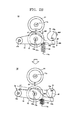
FIGS. 3A and3B are construction diagrams of afusing device 20 having a four-bar link mechanism according to an embodiment.FIG. 3A shows a transition from a separation state to a compression state, andFIG. 3B shows a transition from the compression state to the separation state. - As shown in
FIGS. 3A and3B , the fusingdevice 20 may include afuse roller 21, acompression roller 22, afirst link 23, asecond link 24, athird link 25, acompression spring 26 functioning as an elastic compression member, and acam 27. Thefuse roller 21 may be rotatably supported by a frame (not shown) of an image forming apparatus. Thecompression roller 22 may be rotatably connected to thefirst link 23. Thefirst link 23, which is a member having an approximately rod shape, may have one end (or a rotation support point) 23a rotatably supported by the frame, another end having acontact point 23b of contact with thecam 27, and anintermediate point 23c between therotation support point 23a and thecontact point 23b. Thesecond link 24, which is a member having an approximately triangular shape, may have first throughthird ends first end 24a of thesecond link 24 may be rotatably connected to theintermediate point 23c of thefirst link 23, and thesecond end 24b of thesecond link 24 may rotatably support thecompression roller 22. Thethird link 25, which is a member having an approximately rod shape, may have one end (or a rotation support point) 25a rotatably supported and anotherend 25b rotatably connected to thethird end 24c of thesecond link 24. Thecompression spring 26 may have oneend 26a fixed to the frame and anotherend 26b fixed to thefirst link 23. Thecam 27 may be rotatably supported by the frame to contact thecontact point 23b of the other end of thefirst link 23 and rotated by a motor (not shown). - In the
fusing device 20 shown inFIGS. 3A and3B , therotation support point 23a of thefirst link 23 and therotation support point 25a of thethird link 25 may be disposed along a line approximately parallel to a direction in which aroller axis 21 a of the fusingroller 21 is connected to theroller axis 22a of thecompression roller 22. Also, thesecond link 24 may be disposed such that a distance between thefirst end 24a of thesecond link 24 and therotation support point 23a of thefirst link 23 is greatest, a distance between thethird end 24c of thesecond link 24 and therotation support point 23a of thefirst link 23 is intermediate between the distance between thefirst end 24a of thesecond link 24 and therotation support point 23a of thefirst link 23, and a distance between thesecond end 24b of thesecond link 24 and therotation support point 23a of thefirst link 23 is smallest, among the distances between therotation support point 23a and the first throughthird ends second link 24. - Here, the distance between the
rotation support point 23a of thefirst link 23 and thesecond end 24b of the second link 24 (or theroller axis 22a of the compression roller 22) may be defined as L3, a distance between therotation support point 23a of thefirst link 23 and thecontact point 23b may be defined as L4. Also, a maximum radius of thecam 27 with respect to acam axis 27a may be defined as d3, and a minimum radius of thecam 27 with respect to thecam axis 27a may be defined as d4. -
FIG. 3A shows the transition from the separation state to the compression state. In the compression state, thefirst link 23 may be elastically pressed against by thecompression spring 26 toward the fusingroller 21. Thecam 27 may be in contact with thefirst link 23 while thecam axis 27a is separated from thecontact point 23b by the minimum radius d4. Thesecond link 24 may compress thecompression roller 22 against the fusingroller 21 with rotation of thesecond link 24 controlled by thethird link 23. - During the transition from the separation state to the compression state, the four-bar link mechanism may operate as follows. The
cam 27 may rotate (refer to M11) and make the transition from a state where thecam 27 contacts thefirst link 23 while thecam axis 27a is separated from thecontact point 23b by the maximum distance d3 to a state where thecam 27 contacts thefirst link 23 while thecam axis 27a is separated from thecontact point 23b by the minimum radius d4. Thefirst link 23 may rotate counterclockwise (refer to M12) based on therotation support point 23a with rotation of thecam 27. Thefirst end 24a of thesecond link 24 may be connected to theintermediate point 23c of thefirst link 23 so that thesecond link 24 may be moved toward the fusing roller 21 (refer to M13) with rotation of thefirst link 23. Theother end 25b of thethird link 25 may be connected to thethird end 24c of thesecond link 24 so that thethird link 25 may be rotated counterclockwise (refer to M14) based on therotation support point 25a with motion of thesecond link 24. Thethird end 24c of thesecond link 24 may be connected to theother end 25b of thethird link 25 so that thesecond link 24 may be rotated clockwise based on thefirst end 24a with rotation of thethird link 25. - That is, while being interlocked with the rotation of the
first link 23 and moved toward the fuse roller 21 (refer to M13), thesecond link 24 may be interlocked with the rotation of thethird link 25 and rotate clockwise based on thefirst end 24a (refer to M15). Thus, thesecond end 24b of thesecond link 24 may move toward the fusingroller 21 based on a reference line RL connecting therotation support point 23a of thefirst link 23 and theintermediate point 23c of thefirst link 23, that is, thesecond end 24b of thesecond link 24 may move and protrude toward the fusingroller 21, so that thecompression roller 22 may be compressed against the fusing roller 21 (refer to M16). As a result, thecompression roller 22 may compress a surface of the fusingroller 21 by a compression distance d1' toward theroller axis 21a of the fusingroller 21. -
FIG. 3B shows the transition from the compression state to the separation state. In the separation state, thecam 27 may be in contact with thefirst link 23 while thecam axis 27a is separated from thecontact point 23b by the maximum distance d3. Thefirst link 23 may rotate away from the fusingroller 21, against thecompression spring 26. Thesecond link 24 may separate thecompression roller 22 from the fusingroller 21 with rotation of thesecond link 24 controlled by thethird link 25. - During the transition from the compression state to the separation state, the four-bar link mechanism may operate as follows. The
cam 27 may rotate (refer to M17) and make the transition from the state where thecam 27 contacts thefirst link 23 while thecam axis 27a is separated from thecontact point 23b by the minimum distance d4 to the state where thecam 27 contacts thefirst link 23 while thecam axis 27a is separated from thecontact point 23b by the maximum distance d3. Thefirst link 23 may rotate clockwise (refer to M18) based on therotation support point 23a with the rotation of thecam 27. Thefirst end 24a of thesecond link 24 may be connected to theintermediate point 23c of thefirst link 23 so that thesecond link 24 may be moved away from the fusingroller 21 with the rotation of thefirst link 23. Theother end 25b of thethird link 25 may be connected to thethird end 24c of thesecond link 24 so that thethird link 25 may be rotated clockwise (refer to M20) based on therotation support point 25a with the motion of thesecond link 24. Thethird end 24c of thesecond link 24 may be bonded to theother end 25b of thethird link 25 so that thesecond link 24 may be rotated counterclockwise (refer to M21) based on thefirst end 24a with the rotation of thethird link 25. - That is, while being interlocked with the rotation of the
first link 23 and moved away from the fusing roller 21 (refer to M19), thesecond link 24 may be interlocked with the rotation of thethird link 25 and rotate counterclockwise (refer to M21) based on thefirst end 24a. Thus, thesecond end 24b of thesecond link 24 may move away from the fusingroller 21 based on the reference line RL connecting therotation support point 23a of thefirst link 23 and theintermediate point 23c, that is, thesecond end 24b of thesecond link 24 may move and protrude away from the fusingroller 21, so that thecompression roller 22 may be separated from the fusingroller 21. As a result, thecompression roller 22 may be separated from the surface of the fusingroller 21 by a separation distance d2'. The separation distance d2' is greater than d3x(L3/L4), where d2' is a maximum operation distance of the compression roller, L3 is a distance between the rotation support point of the first link and a rotation support point of the compression roller, L4 is a distance between the rotation support point of the first link and the contact point with the cam, and d3 is an operation radius of the cam. -
FIG. 4 is a diagram showing an increasing tendency of an operation distance of thecompression roller 22. InFIG. 4 , an abscissa denotes a variation in operation amount of thecam 27, and an ordinate denotes a variation in the operation distance of thecompression roller 22. - Here, the operation amount of the
cam 27 is a function of a distance between thecam axis 27a of thecam 27 and thecontact point 23b of thefirst link 23. The operation amount of thecam 27 may be 0 in the separation state where the maximum radius of thecam 27 is d3, and reach a maximum value in the compression state where the minimum radius of thecam 27 is d4. Similarly, the operation distance of thecompression roller 22 may be a function of a distance between theroller axis 21a of thefuse roller 21 and theroller axis 22a of thecompression roller 22. The operation distance of thecompression roller 22 may be 0 in the separation state and reach a maximum value in the compression state. -
FIG. 4 is a graph showing a comparison in between an operation distance of thecompression roller 12 of the simple lever mechanism and the operation distance of thecompression roller 22 of the four-bar link mechanism. In both the simple lever mechanism and the four-bar link mechanism, the lever ratio of thecompression lever 13 may be about equal to that of the first link 23 (L1/L2 ≒ L3/L4 ≒ 0.5), thecam 15 may have the same maximum and minimum radii d3 and d4 as thecam 27. - In the simple lever mechanism, the operation distance of the
compression roller 12 may be about 0.5 times an operation amount of thecam 15. By comparison, in the four-bar link mechanism, the operation distance of thecompression roller 22 may be about the operation amount of thecam 27, that is, twice the operation distance of thecompression roller 12 of the simple lever mechanism. Accordingly, even if an operation radius of a cam or a lever ratio is not increased, a maximum operation distance of thecompression roller 22 may be increased more than a maximum operation distance (d3xL3/L4=0.5xd3) obtained using the lever ratio. Also, the operation distance of thecompression roller 22 may be approximately linearly proportional to the operation amount of thecam 27. - Furthermore, the above-described operation distance of the
compression roller 22 of the four-bar link mechanism may become more than the operation amount of thecam 27 by changing, for example, the arrangement or shape of the link mechanism or thecam 27. Accordingly, there may be a greater degree of freedom in designing thefusing device 2. - Referring to
FIG. 4 , the operation distance of thecompression roller 22 tends to increase approximately linearly initially and then gradually increase near the maximum operation distance of thecompression roller 22. Fusing conditions (e.g., a compression distance) may vary due to mechanical errors of thefusing device 2. To minimize variations in the fusing conditions near the maximum operation distance of thecompression roller 22, thefusing device 2 may sometimes need to gradually increase the operation distance of thecompression roller 22 near the maximum operation distance of thecompression roller 22. By gradually increasing the operation distance of thecompression roller 22 near the maximum operation distance of thecompression roller 22, influence of the variations in the fusing conditions on the operation distance of thecompression roller 22 may be relatively suppressed. - In addition, the
fusing device 2 may need to maximize the operation distance of thecompression roller 22. By maximizing the operation distance of thecompression roller 22, a sufficient fusing nip N may be ensured, and thefusing device 2 and the image forming apparatus may be downscaled. -
FIG. 5 is a graph for explaining a variation in an increasing tendency of the operation distance of thecompression roller 22 according to an arrangement of a link mechanism. InFIG. 5 , an abscissa denotes the operation amount of thecam 27, and an ordinate denotes the operation distance of thecompression roller 22.FIG. 5 is also a schematic view of a motion track of thesecond end 24b of the second link 24 (i.e., theroller axis 22a of the compression roller 22). - In connection with
FIG. 5 ,FIG. 6 shows that an angle Θ between an auxiliary line AL and thesecond end 24b of thesecond link 24 based on thefirst end 24a of thesecond link 24 is defined as a reference angle Θ. That is, the reference angle Θ refers to an angle formed by the auxiliary line AL with a line L12 connecting the first and second ends 24a and 24b of thesecond link 24, based on thefirst end 24a of thesecond link 24. Here, the auxiliary line AL is defined as a line that extends from thefirst end 24a perpendicularly to an operation direction of the compression roller 22 (or a direction in which theroller axis 21a of the fusingroller 21 is connected to theroller axis 22a of the compression roller 22). The reference angle Θ may be changed between the separation state of thecompression roller 22 and the compression state of thecompression roller 22. For example, in the embodiment ofFIGS. 3A and3B , the reference angle Θ may increase during the transition from the separation state to the compression state. A variation range of the reference angle Θ may depend on the arrangement of the link mechanism. - Here, the
second link 24 may rotate with rotation of thecam 27 while the rotation of thesecond link 24 is controlled by thethird link 25, and thesecond end 24b of thesecond link 24 may move with the rotation of thesecond link 24. Also, a distance by which thesecond end 24b moves in the operation direction of thecompression roller 22 may increase toward the reference angle Θ of 180° and reduce away from the reference angle Θ of 180° with respect to the operation amount of thecam 27. - That is, as shown in
FIG. 5 , the increasing tendency (or a slope) of the operation distance of thecompression roller 22 may increase toward the reference angle Θ of 180° and decrease away from the reference angle Θ of 180°. More specifically, the operation distance of thecompression roller 22 may convexly increase with an increase in the operation amount of thecam 27 within the range of the reference angle Θ of 180° or higher and concavely increase with the increase in the operation amount of thecam 27 within the range of the reference angle ⊖ of lower than 180°. - Accordingly, in order to gradually increase the operation distance of the
compression roller 22 near the maximum operation distance, it may be only necessary to vary the reference angle Θ within a range in which the increasing tendency of the operation distance gradually decreases near the maximum operation distance, for example, within a range R1 of about 160° to about 270°. For instance, when the reference angle Θ is varied within a range R2 of about 160° to 220°, the increasing tendency of the operation distance may increase within a range of about 160° to 200° and become relatively lower within a range of about 200° to 220°. The reference angle Θ may be varied not only within the above-described range but also within another range, for example, within a range R3 of about 180° to 220° or within a range R4 of about 230° to 270°. Even if the reference angle Θ is varied within any range, the operation distance of thecompression roller 22 may gradually increase near the maximum operation distance. - In addition, to maximize the operation distance of the
compression roller 22, it may be only necessary to vary the reference angle Θ within a range in which the increasing tendency of the operation distance is maximized, that is, within a range of 180°-α to 180°+α. For example, when the reference angle Θ is varied within a range R5 of about 160° to about 200° (α=20°), the increasing tendency of the operation distance may be increased within both a range of about 160° to 180° and a range of about 180° to about 200°, thereby maximizing the total operation distance. In another example, the reference angle Θ may be varied within a range R6 of about 170° to 190° (α=10°). Even if the reference angle Θ is varied within any range, the operation distance of thecompression roller 22 may be maximized. - Furthermore, as shown in
FIG. 4 , to increase the operation distance of thecompression roller 22 approximately linearly, the reference angle Θ may be varied within a range in which the increasing tendency of the operation distance is approximately linear, that is, within a narrow range near about 180°. - 4. Conclusion
- According to the
fusing device 2 and the image forming apparatus according to embodiments as described above, characteristics of compression/separation (or decompression) of the fusingroller 21 by/from thecompression roller 22 may be improved using the four-bar link mechanism. Due to the improved compression/separation characteristics, the maximum operation distance of thecompression roller 22 may be increased or the operation distance of thecompression roller 22 may be gradually increased near the maximum operation distance or maximized. - An embodiment or Embodiments provide a fusing device and an image forming apparatus using the same by which characteristics of compression/separation (or decompression) of a fusing roller by/from a compression roller.
- While it has been particularly shown and described with reference to embodiments thereof, it will be understood by those of ordinary skill in the art that various changes in form and details may be made therein without departing from the spirit and scope of an embodiment or embodiments as defined by the following claims.
- For example, although it is described above that the
cam 27 is rotated by a motor, thecam 27 may be rotated manually. Also, although it is described above that thecompression roller 22 is elastically compressed by thecompression spring 26, thecompression roller 22 may be elastically compressed by an elastic compression unit (or elastic unit) other than thecompression spring 26. Furthermore, although the embodiments describe only a color image forming apparatus, an embodiment or embodiments may be applied likewise to a single-color image forming apparatus. - Although a few embodiments have been shown and described, it would be appreciated by those skilled in the art that changes may be made in these embodiments without departing from the principles of the invention, the scope of which is defined in the claims and their equivalents.
- Attention is directed to all papers and documents which are filed concurrently with or previous to this specification in connection with this application and which are open to public inspection with this specification, and the contents of all such papers and documents are incorporated herein by reference.
- All of the features disclosed in this specification (including any accompanying claims, abstract and drawings), and/or all of the steps of any method or process so disclosed, may be combined in any combination, except combinations where at least some of such features and/or steps are mutually exclusive.
- Each feature disclosed in this specification (including any accompanying claims, abstract and drawings) may be replaced by alternative features serving the same, equivalent or similar purpose, unless expressly stated otherwise. Thus, unless expressly stated otherwise, each feature disclosed is one example only of a generic series of equivalent or similar features.
- The invention is not restricted to the details of the foregoing embodiment(s). The invention extends to any novel one, or any novel combination, of the features disclosed in this specification (including any accompanying claims, abstract and drawings), or to any novel one, or any novel combination, of the steps of any method or process so disclosed.
Claims (6)
- A fusing device comprising:a fusing roller;a compression roller;a cam;a first link having an end as a rotation support point, another end with a contact point with the cam, and an intermediate point between the end and another end thereof;a second link having a first end, a second end, and a third end, the first end rotatably connected to the intermediate point of the first link, and the second end configured to rotatably support the compression roller;a third link having an end rotatably supported and another end rotatably connected to the third end of the second link; andan elastic compression member configured to elastically compress the compression roller against the fusing roller via the first link,wherein the third link controls rotation of the second link such that the second end of the second link moves toward the fusing roller based on a reference line connecting the end of the first link and the intermediate point of the first link when the first link moves toward the fusing roller due to rotation of the cam against an elastic pressure of the elastic compression member, andwherein the third link controls rotation of the second link such that the second end of the second link moves away from the fusing roller based on the reference line when the first link moves away from the fusing roller.
- The device of claim 1, wherein d2'>d3x(L3/L4), where d2' is a maximum operation distance of the compression roller, L3 is a distance between the rotation support point of the first link and a rotation support point of the compression roller, L4 is a distance between the rotation support point of the first link and the contact point with the cam, and d3 is an operation radius of the cam.
- The device of claim 1 or 2, wherein a reference angle between an auxiliary line extending from the first end of the second link perpendicularly to an operation direction of the compression roller and the second end of the second link disposed on an opposite side of the auxiliary line ranges from about 160° to 270° when the compression roller is farthest away from the fusing roller, and an operation distance of the compression roller gradually increases near a maximum operation distance when the compression roller is near the fusing roller.
- The device of claim 1 or 2, wherein a reference angle between an auxiliary line extending from the first end of the second link perpendicularly to an operation direction of the compression roller and the second end of the second link disposed on an opposite side of the auxiliary line is 180°-α or 180°+α when the compression roller is farthest away from the fusing roller, and is 180°+α or 180°-α when the compression roller is nearest to the fusing roller.
- The device of any of preceding claim, wherein the second link has a triangular shape.
- An image forming apparatus comprising the fusing device of any of preceding claim.
Applications Claiming Priority (2)
| Application Number | Priority Date | Filing Date | Title |
|---|---|---|---|
| JP2010283828A JP5632275B2 (en) | 2010-12-20 | 2010-12-20 | Fixing apparatus and image forming apparatus |
| KR1020110043081A KR101725890B1 (en) | 2010-12-20 | 2011-05-06 | fusing apparatus and image forming apparatus using the same |
Publications (3)
| Publication Number | Publication Date |
|---|---|
| EP2466390A2 true EP2466390A2 (en) | 2012-06-20 |
| EP2466390A3 EP2466390A3 (en) | 2015-12-23 |
| EP2466390B1 EP2466390B1 (en) | 2016-08-31 |
Family
ID=45406430
Family Applications (1)
| Application Number | Title | Priority Date | Filing Date |
|---|---|---|---|
| EP11192489.0A Active EP2466390B1 (en) | 2010-12-20 | 2011-12-07 | Fusing device and image forming apparatus using the same |
Country Status (2)
| Country | Link |
|---|---|
| US (1) | US8583018B2 (en) |
| EP (1) | EP2466390B1 (en) |
Families Citing this family (2)
| Publication number | Priority date | Publication date | Assignee | Title |
|---|---|---|---|---|
| TWM480093U (en) * | 2014-02-18 | 2014-06-11 | Avision Inc | Separable fusing device and printer using the same |
| JP6915309B2 (en) * | 2017-03-07 | 2021-08-04 | ブラザー工業株式会社 | Fixing device |
Citations (2)
| Publication number | Priority date | Publication date | Assignee | Title |
|---|---|---|---|---|
| JP2005326524A (en) | 2004-05-13 | 2005-11-24 | Ricoh Co Ltd | Fixing device and image forming apparatus |
| JP2009237188A (en) | 2008-03-27 | 2009-10-15 | Seiko Epson Corp | Belt fixing device and image forming apparatus |
Family Cites Families (11)
| Publication number | Priority date | Publication date | Assignee | Title |
|---|---|---|---|---|
| JPH06104515B2 (en) * | 1985-02-20 | 1994-12-21 | オリンパス光学工業株式会社 | Recording paper transport path opening mechanism |
| JPH06301309A (en) | 1993-04-16 | 1994-10-28 | Hitachi Koki Co Ltd | Electrophotographic fixing device |
| JPH0720743A (en) | 1993-06-30 | 1995-01-24 | Hitachi Koki Co Ltd | Fixing device and method for electrophotographic device |
| US7050747B2 (en) * | 2001-05-25 | 2006-05-23 | Konica Minolta Holdings, Inc. | Pressure applying device to fixing roller of image forming apparatus |
| JP4090375B2 (en) * | 2003-03-24 | 2008-05-28 | 株式会社沖データ | Fixing apparatus and image forming apparatus |
| JP4135546B2 (en) | 2003-03-31 | 2008-08-20 | マツダ株式会社 | Variable valve gear for engine |
| JP4419823B2 (en) | 2004-12-08 | 2010-02-24 | コニカミノルタビジネステクノロジーズ株式会社 | Fixing device and image forming apparatus having the fixing device |
| JP5141186B2 (en) * | 2007-10-26 | 2013-02-13 | 株式会社リコー | Fixing apparatus and image forming apparatus having the same |
| JP2009281164A (en) | 2008-05-20 | 2009-12-03 | Hitachi Automotive Systems Ltd | Variable valve gear of internal combustion engine |
| US8417166B2 (en) * | 2008-07-11 | 2013-04-09 | Konica Minolta Business Technologies, Inc. | Image forming apparatus with a deviation absorbing transfer apparatus |
| JP5503197B2 (en) * | 2009-06-22 | 2014-05-28 | キヤノン株式会社 | Image heating device |
-
2011
- 2011-11-09 US US13/373,238 patent/US8583018B2/en active Active
- 2011-12-07 EP EP11192489.0A patent/EP2466390B1/en active Active
Patent Citations (2)
| Publication number | Priority date | Publication date | Assignee | Title |
|---|---|---|---|---|
| JP2005326524A (en) | 2004-05-13 | 2005-11-24 | Ricoh Co Ltd | Fixing device and image forming apparatus |
| JP2009237188A (en) | 2008-03-27 | 2009-10-15 | Seiko Epson Corp | Belt fixing device and image forming apparatus |
Also Published As
| Publication number | Publication date |
|---|---|
| US20120155931A1 (en) | 2012-06-21 |
| EP2466390B1 (en) | 2016-08-31 |
| US8583018B2 (en) | 2013-11-12 |
| EP2466390A3 (en) | 2015-12-23 |
Similar Documents
| Publication | Publication Date | Title |
|---|---|---|
| US6400913B1 (en) | Control registration and motion quality of a tandem xerographic machine using transfuse | |
| US8494387B2 (en) | Color-image forming apparatus | |
| US7787787B2 (en) | Image forming apparatus including controller driving image carriers | |
| US8340552B2 (en) | Image forming apparatus | |
| US20170242371A1 (en) | Image forming apparatus | |
| US9250577B2 (en) | Transfer unit including a belt unit with a moving assembly, and image forming apparatus thereof | |
| US9116471B2 (en) | Image forming apparatus | |
| US8385777B2 (en) | Drive transmission mechanism and image forming apparatus including same | |
| US7702275B2 (en) | Cleaning device | |
| EP2466390B1 (en) | Fusing device and image forming apparatus using the same | |
| US9709928B2 (en) | Drive mechanism for an intermediate transfer member module of an electrophotographic imaging device | |
| US8509652B2 (en) | Image forming apparatus | |
| JP2010020184A (en) | Transfer unit and image forming device | |
| JP6326331B2 (en) | Transfer device and image forming apparatus having the same | |
| US9170518B2 (en) | Method and system for closed-loop control of nip width and image transfer field uniformity for an image transfer system | |
| JP2011197113A (en) | Drive transmission device, fixing device and image forming apparatus | |
| KR101725890B1 (en) | fusing apparatus and image forming apparatus using the same | |
| JP6573384B2 (en) | Belt conveying apparatus and image forming apparatus | |
| JP5952012B2 (en) | Image forming apparatus and image forming method | |
| JP6903995B2 (en) | Image forming device | |
| JP4854257B2 (en) | Image forming apparatus | |
| US20120213560A1 (en) | Image forming apparatus | |
| JP2020170194A (en) | Image forming apparatus | |
| JP2019174556A (en) | Image formation apparatus | |
| JP2009103898A (en) | Image forming apparatus |
Legal Events
| Date | Code | Title | Description |
|---|---|---|---|
| PUAI | Public reference made under article 153(3) epc to a published international application that has entered the european phase |
Free format text: ORIGINAL CODE: 0009012 |
|
| AK | Designated contracting states |
Kind code of ref document: A2 Designated state(s): AL AT BE BG CH CY CZ DE DK EE ES FI FR GB GR HR HU IE IS IT LI LT LU LV MC MK MT NL NO PL PT RO RS SE SI SK SM TR |
|
| AX | Request for extension of the european patent |
Extension state: BA ME |
|
| RAP1 | Party data changed (applicant data changed or rights of an application transferred) |
Owner name: SAMSUNG ELECTRONICS CO., LTD. |
|
| PUAL | Search report despatched |
Free format text: ORIGINAL CODE: 0009013 |
|
| AK | Designated contracting states |
Kind code of ref document: A3 Designated state(s): AL AT BE BG CH CY CZ DE DK EE ES FI FR GB GR HR HU IE IS IT LI LT LU LV MC MK MT NL NO PL PT RO RS SE SI SK SM TR |
|
| AX | Request for extension of the european patent |
Extension state: BA ME |
|
| RIC1 | Information provided on ipc code assigned before grant |
Ipc: G03G 15/20 20060101AFI20151113BHEP |
|
| 17P | Request for examination filed |
Effective date: 20160425 |
|
| RBV | Designated contracting states (corrected) |
Designated state(s): AL AT BE BG CH CY CZ DE DK EE ES FI FR GB GR HR HU IE IS IT LI LT LU LV MC MK MT NL NO PL PT RO RS SE SI SK SM TR |
|
| GRAP | Despatch of communication of intention to grant a patent |
Free format text: ORIGINAL CODE: EPIDOSNIGR1 |
|
| GRAS | Grant fee paid |
Free format text: ORIGINAL CODE: EPIDOSNIGR3 |
|
| INTG | Intention to grant announced |
Effective date: 20160628 |
|
| GRAA | (expected) grant |
Free format text: ORIGINAL CODE: 0009210 |
|
| AK | Designated contracting states |
Kind code of ref document: B1 Designated state(s): AL AT BE BG CH CY CZ DE DK EE ES FI FR GB GR HR HU IE IS IT LI LT LU LV MC MK MT NL NO PL PT RO RS SE SI SK SM TR |
|
| REG | Reference to a national code |
Ref country code: CH Ref legal event code: EP Ref country code: GB Ref legal event code: FG4D |
|
| REG | Reference to a national code |
Ref country code: IE Ref legal event code: FG4D |
|
| REG | Reference to a national code |
Ref country code: DE Ref legal event code: R096 Ref document number: 602011029781 Country of ref document: DE |
|
| REG | Reference to a national code |
Ref country code: AT Ref legal event code: REF Ref document number: 825489 Country of ref document: AT Kind code of ref document: T Effective date: 20161015 |
|
| REG | Reference to a national code |
Ref country code: NL Ref legal event code: FP |
|
| REG | Reference to a national code |
Ref country code: FR Ref legal event code: PLFP Year of fee payment: 6 |
|
| REG | Reference to a national code |
Ref country code: LT Ref legal event code: MG4D |
|
| REG | Reference to a national code |
Ref country code: AT Ref legal event code: MK05 Ref document number: 825489 Country of ref document: AT Kind code of ref document: T Effective date: 20160831 |
|
| PG25 | Lapsed in a contracting state [announced via postgrant information from national office to epo] |
Ref country code: LT Free format text: LAPSE BECAUSE OF FAILURE TO SUBMIT A TRANSLATION OF THE DESCRIPTION OR TO PAY THE FEE WITHIN THE PRESCRIBED TIME-LIMIT Effective date: 20160831 Ref country code: HR Free format text: LAPSE BECAUSE OF FAILURE TO SUBMIT A TRANSLATION OF THE DESCRIPTION OR TO PAY THE FEE WITHIN THE PRESCRIBED TIME-LIMIT Effective date: 20160831 Ref country code: NO Free format text: LAPSE BECAUSE OF FAILURE TO SUBMIT A TRANSLATION OF THE DESCRIPTION OR TO PAY THE FEE WITHIN THE PRESCRIBED TIME-LIMIT Effective date: 20161130 Ref country code: RS Free format text: LAPSE BECAUSE OF FAILURE TO SUBMIT A TRANSLATION OF THE DESCRIPTION OR TO PAY THE FEE WITHIN THE PRESCRIBED TIME-LIMIT Effective date: 20160831 Ref country code: FI Free format text: LAPSE BECAUSE OF FAILURE TO SUBMIT A TRANSLATION OF THE DESCRIPTION OR TO PAY THE FEE WITHIN THE PRESCRIBED TIME-LIMIT Effective date: 20160831 |
|
| PG25 | Lapsed in a contracting state [announced via postgrant information from national office to epo] |
Ref country code: ES Free format text: LAPSE BECAUSE OF FAILURE TO SUBMIT A TRANSLATION OF THE DESCRIPTION OR TO PAY THE FEE WITHIN THE PRESCRIBED TIME-LIMIT Effective date: 20160831 Ref country code: LV Free format text: LAPSE BECAUSE OF FAILURE TO SUBMIT A TRANSLATION OF THE DESCRIPTION OR TO PAY THE FEE WITHIN THE PRESCRIBED TIME-LIMIT Effective date: 20160831 Ref country code: GR Free format text: LAPSE BECAUSE OF FAILURE TO SUBMIT A TRANSLATION OF THE DESCRIPTION OR TO PAY THE FEE WITHIN THE PRESCRIBED TIME-LIMIT Effective date: 20161201 Ref country code: AT Free format text: LAPSE BECAUSE OF FAILURE TO SUBMIT A TRANSLATION OF THE DESCRIPTION OR TO PAY THE FEE WITHIN THE PRESCRIBED TIME-LIMIT Effective date: 20160831 Ref country code: SE Free format text: LAPSE BECAUSE OF FAILURE TO SUBMIT A TRANSLATION OF THE DESCRIPTION OR TO PAY THE FEE WITHIN THE PRESCRIBED TIME-LIMIT Effective date: 20160831 |
|
| REG | Reference to a national code |
Ref country code: NL Ref legal event code: PD Owner name: S-PRINTING SOLUTION CO., LTD.; KO Free format text: DETAILS ASSIGNMENT: CHANGE OF OWNER(S), ASSIGNMENT; FORMER OWNER NAME: SAMSUNG ELECTRONICS CO., LTD. Effective date: 20170221 |
|
| RAP2 | Party data changed (patent owner data changed or rights of a patent transferred) |
Owner name: S-PRINTING SOLUTION CO., LTD. |
|
| PG25 | Lapsed in a contracting state [announced via postgrant information from national office to epo] |
Ref country code: EE Free format text: LAPSE BECAUSE OF FAILURE TO SUBMIT A TRANSLATION OF THE DESCRIPTION OR TO PAY THE FEE WITHIN THE PRESCRIBED TIME-LIMIT Effective date: 20160831 Ref country code: RO Free format text: LAPSE BECAUSE OF FAILURE TO SUBMIT A TRANSLATION OF THE DESCRIPTION OR TO PAY THE FEE WITHIN THE PRESCRIBED TIME-LIMIT Effective date: 20160831 |
|
| REG | Reference to a national code |
Ref country code: GB Ref legal event code: 732E Free format text: REGISTERED BETWEEN 20170406 AND 20170412 |
|
| PG25 | Lapsed in a contracting state [announced via postgrant information from national office to epo] |
Ref country code: PT Free format text: LAPSE BECAUSE OF FAILURE TO SUBMIT A TRANSLATION OF THE DESCRIPTION OR TO PAY THE FEE WITHIN THE PRESCRIBED TIME-LIMIT Effective date: 20170102 Ref country code: SK Free format text: LAPSE BECAUSE OF FAILURE TO SUBMIT A TRANSLATION OF THE DESCRIPTION OR TO PAY THE FEE WITHIN THE PRESCRIBED TIME-LIMIT Effective date: 20160831 Ref country code: SM Free format text: LAPSE BECAUSE OF FAILURE TO SUBMIT A TRANSLATION OF THE DESCRIPTION OR TO PAY THE FEE WITHIN THE PRESCRIBED TIME-LIMIT Effective date: 20160831 Ref country code: PL Free format text: LAPSE BECAUSE OF FAILURE TO SUBMIT A TRANSLATION OF THE DESCRIPTION OR TO PAY THE FEE WITHIN THE PRESCRIBED TIME-LIMIT Effective date: 20160831 Ref country code: BE Free format text: LAPSE BECAUSE OF FAILURE TO SUBMIT A TRANSLATION OF THE DESCRIPTION OR TO PAY THE FEE WITHIN THE PRESCRIBED TIME-LIMIT Effective date: 20160831 Ref country code: BG Free format text: LAPSE BECAUSE OF FAILURE TO SUBMIT A TRANSLATION OF THE DESCRIPTION OR TO PAY THE FEE WITHIN THE PRESCRIBED TIME-LIMIT Effective date: 20161130 Ref country code: DK Free format text: LAPSE BECAUSE OF FAILURE TO SUBMIT A TRANSLATION OF THE DESCRIPTION OR TO PAY THE FEE WITHIN THE PRESCRIBED TIME-LIMIT Effective date: 20160831 Ref country code: CZ Free format text: LAPSE BECAUSE OF FAILURE TO SUBMIT A TRANSLATION OF THE DESCRIPTION OR TO PAY THE FEE WITHIN THE PRESCRIBED TIME-LIMIT Effective date: 20160831 |
|
| REG | Reference to a national code |
Ref country code: DE Ref legal event code: R097 Ref document number: 602011029781 Country of ref document: DE |
|
| PG25 | Lapsed in a contracting state [announced via postgrant information from national office to epo] |
Ref country code: IT Free format text: LAPSE BECAUSE OF FAILURE TO SUBMIT A TRANSLATION OF THE DESCRIPTION OR TO PAY THE FEE WITHIN THE PRESCRIBED TIME-LIMIT Effective date: 20160831 |
|
| PLBE | No opposition filed within time limit |
Free format text: ORIGINAL CODE: 0009261 |
|
| STAA | Information on the status of an ep patent application or granted ep patent |
Free format text: STATUS: NO OPPOSITION FILED WITHIN TIME LIMIT |
|
| REG | Reference to a national code |
Ref country code: DE Ref legal event code: R082 Ref document number: 602011029781 Country of ref document: DE Representative=s name: GULDE & PARTNER PATENT- UND RECHTSANWALTSKANZL, DE Ref country code: DE Ref legal event code: R081 Ref document number: 602011029781 Country of ref document: DE Owner name: HP PRINTING KOREA CO., LTD., SUWON-SI, KR Free format text: FORMER OWNER: SAMSUNG ELECTRONICS CO., LTD., SUWON-SI, GYEONGGI-DO, KR Ref country code: DE Ref legal event code: R081 Ref document number: 602011029781 Country of ref document: DE Owner name: HEWLETT-PACKARD DEVELOPMENT COMPANY, L.P., SPR, US Free format text: FORMER OWNER: SAMSUNG ELECTRONICS CO., LTD., SUWON-SI, GYEONGGI-DO, KR Ref country code: DE Ref legal event code: R081 Ref document number: 602011029781 Country of ref document: DE Owner name: S-PRINTING SOLUTION CO., LTD., SUWON-SI, KR Free format text: FORMER OWNER: SAMSUNG ELECTRONICS CO., LTD., SUWON-SI, GYEONGGI-DO, KR |
|
| REG | Reference to a national code |
Ref country code: CH Ref legal event code: PL |
|
| 26N | No opposition filed |
Effective date: 20170601 |
|
| PG25 | Lapsed in a contracting state [announced via postgrant information from national office to epo] |
Ref country code: SI Free format text: LAPSE BECAUSE OF FAILURE TO SUBMIT A TRANSLATION OF THE DESCRIPTION OR TO PAY THE FEE WITHIN THE PRESCRIBED TIME-LIMIT Effective date: 20160831 |
|
| PG25 | Lapsed in a contracting state [announced via postgrant information from national office to epo] |
Ref country code: MC Free format text: LAPSE BECAUSE OF FAILURE TO SUBMIT A TRANSLATION OF THE DESCRIPTION OR TO PAY THE FEE WITHIN THE PRESCRIBED TIME-LIMIT Effective date: 20160831 |
|
| REG | Reference to a national code |
Ref country code: IE Ref legal event code: MM4A |
|
| REG | Reference to a national code |
Ref country code: FR Ref legal event code: TP Owner name: S-PRINTING SOLUTION CO., LTD., KR Effective date: 20170912 |
|
| PG25 | Lapsed in a contracting state [announced via postgrant information from national office to epo] |
Ref country code: LI Free format text: LAPSE BECAUSE OF NON-PAYMENT OF DUE FEES Effective date: 20161231 Ref country code: CH Free format text: LAPSE BECAUSE OF NON-PAYMENT OF DUE FEES Effective date: 20161231 Ref country code: LU Free format text: LAPSE BECAUSE OF NON-PAYMENT OF DUE FEES Effective date: 20161207 |
|
| REG | Reference to a national code |
Ref country code: FR Ref legal event code: PLFP Year of fee payment: 7 |
|
| PG25 | Lapsed in a contracting state [announced via postgrant information from national office to epo] |
Ref country code: IE Free format text: LAPSE BECAUSE OF NON-PAYMENT OF DUE FEES Effective date: 20161207 |
|
| PG25 | Lapsed in a contracting state [announced via postgrant information from national office to epo] |
Ref country code: CY Free format text: LAPSE BECAUSE OF FAILURE TO SUBMIT A TRANSLATION OF THE DESCRIPTION OR TO PAY THE FEE WITHIN THE PRESCRIBED TIME-LIMIT Effective date: 20160831 Ref country code: HU Free format text: LAPSE BECAUSE OF FAILURE TO SUBMIT A TRANSLATION OF THE DESCRIPTION OR TO PAY THE FEE WITHIN THE PRESCRIBED TIME-LIMIT; INVALID AB INITIO Effective date: 20111207 |
|
| PG25 | Lapsed in a contracting state [announced via postgrant information from national office to epo] |
Ref country code: IS Free format text: LAPSE BECAUSE OF FAILURE TO SUBMIT A TRANSLATION OF THE DESCRIPTION OR TO PAY THE FEE WITHIN THE PRESCRIBED TIME-LIMIT Effective date: 20160831 Ref country code: MK Free format text: LAPSE BECAUSE OF FAILURE TO SUBMIT A TRANSLATION OF THE DESCRIPTION OR TO PAY THE FEE WITHIN THE PRESCRIBED TIME-LIMIT Effective date: 20160831 Ref country code: TR Free format text: LAPSE BECAUSE OF FAILURE TO SUBMIT A TRANSLATION OF THE DESCRIPTION OR TO PAY THE FEE WITHIN THE PRESCRIBED TIME-LIMIT Effective date: 20160831 |
|
| REG | Reference to a national code |
Ref country code: NL Ref legal event code: HC Owner name: HP PRINTING KOREA CO., LTD.; KR Free format text: DETAILS ASSIGNMENT: CHANGE OF OWNER(S), CHANGE OF OWNER(S) NAME; FORMER OWNER NAME: S-PRINTING SOLUTION CO., LTD. Effective date: 20180816 |
|
| PG25 | Lapsed in a contracting state [announced via postgrant information from national office to epo] |
Ref country code: MT Free format text: LAPSE BECAUSE OF NON-PAYMENT OF DUE FEES Effective date: 20161207 |
|
| PG25 | Lapsed in a contracting state [announced via postgrant information from national office to epo] |
Ref country code: AL Free format text: LAPSE BECAUSE OF FAILURE TO SUBMIT A TRANSLATION OF THE DESCRIPTION OR TO PAY THE FEE WITHIN THE PRESCRIBED TIME-LIMIT Effective date: 20160831 |
|
| REG | Reference to a national code |
Ref country code: DE Ref legal event code: R082 Ref document number: 602011029781 Country of ref document: DE Ref country code: DE Ref legal event code: R081 Ref document number: 602011029781 Country of ref document: DE Owner name: HP PRINTING KOREA CO., LTD., SUWON-SI, KR Free format text: FORMER OWNER: S-PRINTING SOLUTION CO., LTD., SUWON-SI, GYEONGGI-DO, KR Ref country code: DE Ref legal event code: R081 Ref document number: 602011029781 Country of ref document: DE Owner name: HEWLETT-PACKARD DEVELOPMENT COMPANY, L.P., SPR, US Free format text: FORMER OWNER: S-PRINTING SOLUTION CO., LTD., SUWON-SI, GYEONGGI-DO, KR Ref country code: DE Ref legal event code: R082 Ref document number: 602011029781 Country of ref document: DE Representative=s name: SCHOPPE, ZIMMERMANN, STOECKELER, ZINKLER, SCHE, DE |
|
| REG | Reference to a national code |
Ref country code: NL Ref legal event code: PD Owner name: HEWLETT-PACKARD DEVELOPMENT COMPANY, L.P.; US Free format text: DETAILS ASSIGNMENT: CHANGE OF OWNER(S), CHANGE OF LEGAL ENTITY; FORMER OWNER NAME: SAMSUNG ELECTRONICS CO., LTD. Effective date: 20191030 |
|
| REG | Reference to a national code |
Ref country code: DE Ref legal event code: R081 Ref document number: 602011029781 Country of ref document: DE Owner name: HEWLETT-PACKARD DEVELOPMENT COMPANY, L.P., SPR, US Free format text: FORMER OWNER: HP PRINTING KOREA CO., LTD., SUWON-SI, GYEONGGI-DO, KR |
|
| REG | Reference to a national code |
Ref country code: GB Ref legal event code: 732E Free format text: REGISTERED BETWEEN 20191212 AND 20191218 |
|
| REG | Reference to a national code |
Ref country code: DE Ref legal event code: R082 Ref document number: 602011029781 Country of ref document: DE Representative=s name: SCHOPPE, ZIMMERMANN, STOECKELER, ZINKLER, SCHE, DE |
|
| PGFP | Annual fee paid to national office [announced via postgrant information from national office to epo] |
Ref country code: FR Payment date: 20211118 Year of fee payment: 11 Ref country code: NL Payment date: 20211118 Year of fee payment: 11 Ref country code: GB Payment date: 20211118 Year of fee payment: 11 |
|
| PGFP | Annual fee paid to national office [announced via postgrant information from national office to epo] |
Ref country code: DE Payment date: 20220616 Year of fee payment: 12 |
|
| REG | Reference to a national code |
Ref country code: NL Ref legal event code: MM Effective date: 20230101 |
|
| GBPC | Gb: european patent ceased through non-payment of renewal fee |
Effective date: 20221207 |
|
| PG25 | Lapsed in a contracting state [announced via postgrant information from national office to epo] |
Ref country code: NL Free format text: LAPSE BECAUSE OF NON-PAYMENT OF DUE FEES Effective date: 20230101 |
|
| PG25 | Lapsed in a contracting state [announced via postgrant information from national office to epo] |
Ref country code: GB Free format text: LAPSE BECAUSE OF NON-PAYMENT OF DUE FEES Effective date: 20221207 |
|
| PG25 | Lapsed in a contracting state [announced via postgrant information from national office to epo] |
Ref country code: FR Free format text: LAPSE BECAUSE OF NON-PAYMENT OF DUE FEES Effective date: 20221231 |