JP6326331B2 - Transfer device and image forming apparatus having the same - Google Patents
Transfer device and image forming apparatus having the same Download PDFInfo
- Publication number
- JP6326331B2 JP6326331B2 JP2014184743A JP2014184743A JP6326331B2 JP 6326331 B2 JP6326331 B2 JP 6326331B2 JP 2014184743 A JP2014184743 A JP 2014184743A JP 2014184743 A JP2014184743 A JP 2014184743A JP 6326331 B2 JP6326331 B2 JP 6326331B2
- Authority
- JP
- Japan
- Prior art keywords
- roller
- transfer
- transfer belt
- secondary transfer
- transfer device
- Prior art date
- Legal status (The legal status is an assumption and is not a legal conclusion. Google has not performed a legal analysis and makes no representation as to the accuracy of the status listed.)
- Active
Links
Images


Landscapes
- Electrostatic Charge, Transfer And Separation In Electrography (AREA)
Description
この発明は転写装置およびそれを備える画像形成装置に関し、特にたとえば、像担持体に形成されたトナー像を用紙に転写する、転写装置およびそれを備える画像形成装置に関する。 The present invention relates to a transfer device and an image forming apparatus including the transfer device, and more particularly to a transfer device that transfers a toner image formed on an image carrier onto a sheet and an image forming apparatus including the transfer device.
従来、像担持体と転写ベルトとの間に形成されるニップ部(転写領域)に用紙を通過させることによって、像担持体上のトナー像を用紙に転写する電子写真方式の画像形成装置が知られている。このような画像形成装置では、通常使用される普通紙に合わせた設定となっているため、厚紙や封筒などのように普通紙よりも厚みが大きくコシの強い用紙に画像形成する場合、用紙がニップ部に突入する際やニップ部から抜ける際の衝撃によって振動が生じ易く、転写画像にブレが生じ易い。 2. Description of the Related Art Conventionally, an electrophotographic image forming apparatus that transfers a toner image on an image carrier onto a sheet by passing the sheet through a nip (transfer area) formed between the image carrier and a transfer belt is known. It has been. In such an image forming apparatus, since it is set according to the normal paper that is normally used, when forming an image on paper that is thicker and stronger than plain paper, such as thick paper and envelopes, the paper is Vibration is likely to occur due to an impact when entering or exiting the nip portion, and the transferred image is likely to be blurred.
特許文献1には、厚紙にも対応可能な画像形成装置の一例が開示されている。特許文献1の画像形成装置は、一次転写ベルト、一次転写駆動ローラ、二次転写ベルト、二次転写ローラおよびバックアップローラ等を備える。このバックアップローラは、二次転写ローラの用紙搬送方向における上流側において二次転写ベルトを張架し、一次転写駆動ローラに離接する方向に変位可能とされる。そして、モノクロ画像形成モードにおいて用紙が厚紙である場合には、バックアップローラが一次転写駆動ローラ側に近づくように変位され、ニップ幅が用紙搬送方向における上流側に広げられる。これによって、用紙が厚紙の場合でも、一次転写ベルトの振動が抑制されると共に、一次転写ベルトと二次転写ベルトとの間のニップ幅が確保されて、転写不良の発生が抑制される。 Patent Document 1 discloses an example of an image forming apparatus that can handle thick paper. The image forming apparatus of Patent Document 1 includes a primary transfer belt, a primary transfer driving roller, a secondary transfer belt, a secondary transfer roller, a backup roller, and the like. The backup roller can be displaced in a direction in which the secondary transfer belt is stretched on the upstream side of the secondary transfer roller in the sheet conveyance direction and is separated from and contacted with the primary transfer driving roller. When the paper is thick in the monochrome image forming mode, the backup roller is displaced so as to approach the primary transfer driving roller, and the nip width is widened upstream in the paper transport direction. As a result, even when the paper is a thick paper, the vibration of the primary transfer belt is suppressed, and the nip width between the primary transfer belt and the secondary transfer belt is secured, thereby preventing the occurrence of transfer failure.
特許文献1の画像形成装置では、用紙が厚紙の場合には、バックアップローラを単独で一次転写駆動ローラ側に近づけてニップ幅を広げることによって、一次転写ベルトの振動およびそれに起因する転写不良の発生を抑制している。しかしながら、特許文献1の画像形成装置では、一次転写ベルトと二次転写ベルトとの間の押圧力は変わらないので、厚紙先端がニップ部に突入する際や厚紙後端がニップ部から抜ける際の衝撃自体は大きいままであり、周辺部材にかかる負荷も大きいままである。また、バックアップローラを一次転写駆動ローラ側に近づけるので、ニップ部への突入口が狭くなり、厚紙がニップ部に突入し難くなる。 In the image forming apparatus of Patent Document 1, when the paper is thick paper, the backup roller alone is brought close to the primary transfer driving roller side to widen the nip width, thereby generating vibration of the primary transfer belt and transfer failure caused by the vibration. Is suppressed. However, in the image forming apparatus disclosed in Patent Document 1, the pressing force between the primary transfer belt and the secondary transfer belt does not change. Therefore, when the leading end of the thick paper enters the nip portion or when the trailing end of the thick paper slips out of the nip portion. The impact itself remains large and the load on the peripheral members remains large. Further, since the backup roller is brought closer to the primary transfer driving roller side, the entrance to the nip portion is narrowed and it is difficult for the cardboard to enter the nip portion.
それゆえに、この発明の主たる目的は、新規な、転写装置およびそれを備える画像形成装置を提供することである。 Therefore, a main object of the present invention is to provide a novel transfer apparatus and an image forming apparatus including the same.
この発明の他の目的は、コシの強い厚紙等に画像を形成する際の転写画像ブレを抑制できる、転写装置およびそれを備える画像形成装置を提供することである。 Another object of the present invention is to provide a transfer device and an image forming apparatus provided with the transfer device that can suppress transfer image blurring when an image is formed on thick paper or the like that is strong.
第1の発明は、像担持体に形成されたトナー像を用紙に転写する転写装置であって、複数のローラによって周回移動可能に張架され、像担持体との間でニップ部を形成する転写ベルト、転写ベルトを挟んで像担持体に対向して配置され、ニップ部に転写電界を形成する転写ローラ、転写ローラの用紙搬送方向における上流側において転写ベルトを張架するバックアップローラ、および像担持体に対する転写装置の配置位置を少なくとも第1接触位置と第2接触位置とに変位可能な変位機構を備え、第1接触位置は、像担持体と転写ベルトとが第1所定圧で接触するように転写ローラが当該転写ベルトを押圧し、かつバックアップローラが像担持体に最も接近する位置であり、第2接触位置は、像担持体と転写ベルトとが第1所定圧より小さい第2所定圧で接触するように転写ローラが当該転写ベルトを押圧し、かつバックアップローラが第1接触位置における位置よりも所定距離だけ像担持体から離れる位置であって、変位機構は、上端部が段差状に形成される係止部と、係止部の上端部に係止されることによって、転写装置の配置位置を所望位置で保持する保持部材とを含む、転写装置である。 A first invention is a transfer device for transferring a toner image formed on an image carrier onto a sheet, and is stretched around a plurality of rollers so as to be able to move around to form a nip portion with the image carrier. A transfer belt, a transfer roller disposed opposite to the image carrier with the transfer belt interposed therebetween, and forming a transfer electric field in the nip portion; a backup roller that stretches the transfer belt upstream of the transfer roller in the paper transport direction; and an image A displacement mechanism is provided that can displace the arrangement position of the transfer device with respect to the carrier to at least a first contact position and a second contact position. The first contact position causes the image carrier and the transfer belt to contact at a first predetermined pressure. In this way, the transfer roller presses the transfer belt and the backup roller is closest to the image carrier, and the second contact position is such that the image carrier and the transfer belt are smaller than the first predetermined pressure. Transfer roller into contact with 2 predetermined pressure presses the transfer belt, and I position der backup roller is separated from a predetermined distance image bearing member than the position in the first contact position, the displacement mechanism has an upper end portion Is a transfer device including a locking portion formed in a step shape and a holding member that holds the arrangement position of the transfer device at a desired position by being locked to the upper end portion of the locking portion .
第1の発明では、転写装置は、像担持体に形成されたトナー像を用紙に転写するための装置であって、転写ベルト、転写ローラおよびバックアップローラを備える。また、転写装置は、自身の配置位置を第1接触位置と第2接触位置とに変位可能な変位機構を備える。第1接触位置は、普通紙に対して画像を形成するのに適した配置位置である。この第1接触位置では、転写ローラは、像担持体と転写ベルトとが第1所定圧で接触するように転写ベルトを押圧する位置に配置され、バックアップローラは、転写ベルトを挟んで像担持体に最も接近する位置に配置される。一方、第2接触位置は、普通紙よりも厚みが大きくコシの強い厚紙等に対して画像を形成するのに適した配置位置である。第2接触位置では、転写ローラは、像担持体と転写ベルトとが第1所定圧よりも小さい第2所定圧で接触するように転写ベルトを押圧する位置に配置され、バックアップローラは、第1接触位置における位置よりも所定距離だけ像担持体から離れた位置に配置される。 In the first invention, the transfer device is a device for transferring a toner image formed on the image carrier onto a sheet, and includes a transfer belt, a transfer roller, and a backup roller. Further, the transfer device includes a displacement mechanism that can displace the arrangement position of the transfer device between the first contact position and the second contact position. The first contact position is an arrangement position suitable for forming an image on plain paper. At the first contact position, the transfer roller is disposed at a position that presses the transfer belt so that the image carrier and the transfer belt are in contact with each other at a first predetermined pressure, and the backup roller is sandwiched between the image belt and the image carrier. It is arranged at the position closest to On the other hand, the second contact position is an arrangement position suitable for forming an image on thick paper or the like that is thicker and stronger than plain paper. In the second contact position, the transfer roller is disposed at a position that presses the transfer belt so that the image carrier and the transfer belt are in contact with each other at a second predetermined pressure that is smaller than the first predetermined pressure. It is arranged at a position away from the image carrier by a predetermined distance from the position at the contact position.
すなわち、第2接触位置では、厚紙等に対応させるため、第1接触位置よりも、像担持体と転写ベルトとの間のニップ部の用紙突入口が広げられると共に、ニップ部における押圧力が小さくされる。これによって、厚紙等の先端がニップ部に突入する際や厚紙等の後端がニップ部から抜ける際の衝撃が低減されるので、転写画像ブレが抑制される。また、転写装置や像担持体にかかる負荷も低減される。 That is, at the second contact position, the paper entrance of the nip portion between the image carrier and the transfer belt is widened and the pressing force at the nip portion is smaller than that of the first contact position in order to correspond to thick paper or the like. Is done. This reduces the impact when the leading edge of cardboard or the like enters the nip part or when the trailing edge of cardboard or the like slips out of the nip part, so that transfer image blur is suppressed. Also, the load on the transfer device and the image carrier is reduced.
第1の発明によれば、普通紙に適した第1接触位置に加えて、第1接触位置よりもニップ部の用紙突入口が広くニップ圧が小さい第2接触位置に変位可能な変位機構を備えるので、コシの強い厚紙等に画像を形成する際の転写画像ブレを適切に抑制できる。 According to the first aspect of the invention, in addition to the first contact position suitable for plain paper, the displacement mechanism capable of being displaced to the second contact position where the paper inlet of the nip portion is wider and the nip pressure is smaller than the first contact position. Therefore, it is possible to appropriately suppress transfer image blurring when an image is formed on thick paper or the like that is strong.
第2の発明は、第1の発明に従属し、変位機構は、転写ローラを挟んでバックアップローラと反対側の部分を支点として転写装置を回転移動させることによって、当該転写装置を第1接触位置と第2接触位置とに変位させる。 A second invention is dependent on the first invention, and the displacement mechanism rotates the transfer device around a portion opposite to the backup roller across the transfer roller, thereby moving the transfer device to the first contact position. And the second contact position.
第2の発明では、転写装置は、転写ローラを挟んでバックアップローラと反対側の部分を支点として回転移動することで、第1接触位置と第2接触位置とに変位される。これによって、像担持体と転写ベルトとの間に形成されるニップ部の幅を保持しつつ、ニップ部の用紙突入口を効果的に広げることができる。 In the second aspect of the invention, the transfer device is displaced between the first contact position and the second contact position by rotating around the transfer roller about the portion opposite to the backup roller. Accordingly, it is possible to effectively widen the paper entrance of the nip portion while maintaining the width of the nip portion formed between the image carrier and the transfer belt.
第3の発明は、第1または第2の発明に従属し、バックアップローラは、第1接触位置においても転写ベルトを挟んで像担持体に接触しない。 A third invention is dependent on the first or the second invention, and the backup roller does not contact the image carrier with the transfer belt sandwiched also in the first contact position.
第3の発明では、バックアップローラの位置が像担持体に最も接近する第1接触位置においても、バックアップローラは、転写ベルトを挟んで像担持体に接触しない。これによって、バックアップローラに影響されることなく、転写装置を変位させる際の位置決めを実行できるので、位置決めの精度が向上する。 In the third aspect of the invention, even at the first contact position where the position of the backup roller is closest to the image carrier, the backup roller does not contact the image carrier across the transfer belt. As a result, positioning when displacing the transfer device can be executed without being affected by the backup roller, so that the positioning accuracy is improved.
第4の発明は、第1ないし第3のいずれかの発明に従属し、変位機構は、さらに、転写ベルトが像担持体から離間する離間位置に転写装置の配置位置を変位可能である。 A fourth invention is dependent on any one of the first to third inventions, and the displacement mechanism can further displace the arrangement position of the transfer device to a separation position where the transfer belt is separated from the image carrier.
第4の発明では、転写装置は、さらに、転写ベルトが像担持体から離間する離間位置に変位可能である。この離間位置は、転写装置が転写動作を長時間実施しない場合などに利用される。 In the fourth invention, the transfer device can be further displaced to a separation position where the transfer belt is separated from the image carrier. This separation position is used when the transfer device does not perform the transfer operation for a long time.
第5の発明は、第1ないし第4のいずれかの発明に従属し、保持部材がユーザに手動操作されることによって転写装置が変位される。 A fifth invention is according to the first to fourth any one of the transfer device is displaced by the hold member is manually operated by the user.
第5の発明では、転写装置は、自身の配置位置を保持するための保持部材を備える。ユーザは、この保持部材を手動操作することによって、転写装置の配置位置を変位可能である。 In a fifth aspect, the transfer device includes a holding member for holding its own arrangement position. The user can move the arrangement position of the transfer device by manually operating the holding member.
第6の発明は、第1ないし第5のいずれかの発明に係る転写装置を備える、画像形成装置である。 A sixth invention is an image forming apparatus including the transfer device according to any one of the first to fifth inventions.
第6に発明によれば、第1の発明と同様の作用効果を奏し、コシの強い厚紙等に画像を形成する際の転写画像ブレを適切に抑制できる。 According to the sixth aspect of the invention, the same effects as those of the first aspect of the invention can be obtained, and transfer image blurring when an image is formed on a thick thick paper or the like can be appropriately suppressed.
この発明によれば、普通紙に適した第1接触位置に加えて、第1接触位置よりもニップ部の用紙突入口が広くニップ圧が小さい第2接触位置に変位可能な変位機構を備えるので、コシの強い厚紙等に画像を形成する際の転写画像ブレを適切に抑制できる。 According to this invention, in addition to the first contact position suitable for plain paper, the displacement mechanism is provided that can be displaced to the second contact position where the paper inlet of the nip portion is wider and the nip pressure is smaller than the first contact position. In addition, it is possible to appropriately suppress transfer image blurring when an image is formed on a thick thick paper or the like.
この発明の上述の目的、その他の目的、特徴および利点は、図面を参照して行う後述の実施例の詳細な説明から一層明らかとなろう。 The above object, other objects, features, and advantages of the present invention will become more apparent from the following detailed description of embodiments with reference to the drawings.
[第1実施例]
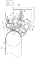
図1および図2を参照して、この発明の第1実施例である二次転写ユニット10は、像担持体の一例である中間転写ベルト32に形成されたトナー像を用紙に転写するための転写装置であって、電子写真方式によって用紙に画像を形成する画像形成装置100に用いられる。詳細は後述するように、二次転写ユニット10は、中間転写ベルト32に対する自身の配置位置を変位可能な変位機構を備え、用紙の種類に合わせて配置位置が変更されることで、普通紙に加えて、厚紙、封筒およびOHPフィルム等のように普通紙よりも厚みが大きくコシの強い用紙(以下、これらコシの強い用紙をまとめて「厚紙等」と言うことがある。)に対しても適切にトナー像を転写できるようにしている。
[First embodiment]
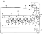
Referring to FIGS. 1 and 2, a
先ず、画像形成装置100の基本構成について概略的に説明する。図1に示すように、画像形成装置100は、カラープリンタであって、用紙に多色または単色の画像を形成する。ただし、画像形成装置は、モノクロプリンタであってもよい。また、この発明に係る転写装置が適用される画像形成装置は、プリンタに限定される必要はなく、コピー機またはファクシミリ或いはこれらの機能を備えた複合機であってもよい。
First, the basic configuration of the
画像形成装置100は、感光体ドラム12、現像装置14、帯電器16、クリーニングユニット18、露光装置20、中間転写ユニット22、二次転写ユニット10および定着ユニット24等のコンポーネントを備え、給紙トレイ26から搬送される用紙上に画像を形成し、画像形成済みの用紙を排出トレイ28に排出する。用紙上に画像を形成するための画像データとしては、外部コンピュータから入力される画像データが利用される。ただし、画像形成装置100がスキャナ機能を備える場合には、外部から入力される画像データのみならず、スキャナによって原稿から読み取った画像データを利用することもできる。
The
上述の各コンポーネントは、画像形成装置100の筐体102内に収容される。また、筐体102内には、CPUおよびメモリ等を含む制御部30が設けられる。制御部30は、画像形成装置100の各部位に制御信号を送信し、画像形成装置100に種々の動作を実行させる。
Each of the components described above is housed in the
ここで、画像形成装置100において扱われる画像データは、ブラック(BK)、マゼンタ(M)、シアン(C)およびイエロー(Y)の4色のカラー画像に応じたものである。このため、感光体ドラム12、現像装置14、帯電器16およびクリーニングユニット18のそれぞれは、各色に応じた4種類の潜像を形成するように4個ずつ設けられ、これらによって4つの画像ステーションが構成される。4つの画像ステーションは、中間転写ベルト32の表面の走行方向(周回移動方向)に沿って一列に並んで配置され、中間転写ベルト32の走行方向における下流側から、つまり二次転写ユニット10に近い側から、ブラック用、マゼンタ用、シアン用およびイエロー用の順に配置される。
Here, the image data handled in the
感光体ドラム12は、導電性を有する円筒状の基体の表面に感光層が形成された像担持体であり、帯電器16は、この感光体ドラム12の表面を所定の電位に帯電させる部材である。また、露光装置20は、レーザ出射部および反射ミラー等を備えたレーザスキャニングユニット(LSU)として構成され、帯電された感光体ドラム12の表面を露光することによって、画像データに応じた静電潜像を感光体ドラム12の表面に形成する。現像装置14は、感光体ドラム12の表面に形成された静電潜像を4色(YMCK)のトナーによって顕像化するものである。また、クリーニングユニット18は、現像および画像転写後における感光体ドラム12の表面に残留したトナーを除去する。
The
中間転写ユニット(一次転写ユニット)22は、中間転写ベルト32、駆動ローラ34、従動ローラ36および4つの中間転写ローラ38等を備え、感光体ドラム12の上方に配置される。
The intermediate transfer unit (primary transfer unit) 22 includes an
中間転写ベルト32は、駆動ローラ34および従動ローラ36等の複数のローラによって張架される無端帯状のベルトであって、その表面(外周面)が感光体ドラム12の表面に当接するように配置される。中間転写ベルト32は、駆動ローラ38の回転駆動に伴い、所定方向(図1では反時計回り)に回転(周回移動)する。後述のように、この中間転写ベルト32の表面には、感光体ドラム12に形成されたトナー像が転写(一次転写)されることによって、トナー像が形成される。すなわち、中間転写ベルト32は、その表面にトナー像が形成される像担持体として機能する。
The
駆動ローラ34は、図示しない駆動部によってその軸線回りに回転可能に設けられる。従動ローラ36は、中間転写ベルト32の周回移動に伴って回転すると共に、中間転写ベルト32に一定の張力を与えて中間転写ベルト36の弛みを防止する。
The
中間転写ローラ38は、中間転写ベルト32を挟んで各感光体ドラム12と対向する位置のそれぞれに配置され、中間転写ベルト32の内周面に圧接されて中間転写ベルト32の周回移動に伴い回転する。図示は省略するが、この中間転写ローラ38には、転写バイアスを印加する転写電源が接続される。画像形成時には、感光体ドラム12の表面に形成されたトナー像を構成するトナーの帯電極性とは逆極性の電圧が中間転写ローラ38に印加される。これによって、感光体ドラム12と中間転写ベルト32との間に転写電界が形成され、この転写電界の作用によって、感光体ドラム12に形成されたトナー像が中間転写ベルト32の外周面に転写される。たとえば、カラー画像を形成する場合には、各感光体ドラム12に形成された各色のトナー像が中間転写ベルト32に順次重ねて転写されて、中間転写ベルト32の外周面に多色のトナー像が形成される。
The
また、駆動ローラ34の近傍には、二次転写ベルト50および二次転写ローラ52等を備える二次転写ユニット10が配置される。筐体102の背面側(図1では右側)の壁には、筐体102内を点検等するためのドアユニット104が開閉自在に設けられており、二次転写ユニット10は、このドアユニット104に設けられた支持フレーム106に対して変位可能に取り付けられる。そして、この二次転写ユニット10(厳密には二次転写ベルト50)と中間転写ベルト32との間に形成されるニップ部(転写ニップ域)70を用紙が通過することによって、中間転写ベルト32に形成されたトナー像が用紙に転写される。二次転写ユニット10の具体的構成については後述する。
Further, in the vicinity of the driving
定着ユニット24は、ヒートローラおよび加圧ローラ等を備え、二次転写ユニット10の上方に配置される。ヒートローラは、所定の定着温度となるように設定されており、ヒートローラと加圧ローラとの間の定着ニップ域を用紙が通過することによって、用紙に転写されたトナー像が溶融、混合および圧接されて、用紙に対してトナー像が熱定着される。
The fixing
また、画像形成装置100の筐体102内には、給紙トレイ26に載置された用紙を二次転写ユニット10および定着ユニット24を経由させて排紙トレイ28に送るための用紙搬送路が形成される。この用紙搬送路には、搬送ローラ40,42,44およびレジストローラ46等の用紙搬送手段が適宜配置される。
In addition, a paper conveyance path for sending the paper placed on the
画像形成時には、給紙トレイ26に載置された用紙が図示しないピックアップローラによって1枚ずつ用紙搬送路に導かれ、搬送ローラ42によってレジストローラ46まで搬送される。そして、レジストローラ46によって、用紙の先端と中間転写ベルト32上のトナー像の先端とが整合するタイミングで、中間転写ベルト32と二次転写ベルト50との間のニップ部70に用紙が搬送され、用紙上にトナー像が転写される。その後、定着ユニット24を通過することによって用紙上の未定着トナーが熱で溶融して固着され、搬送ローラ42,44を経て排紙トレイ28上に用紙が排出される。
At the time of image formation, the sheets placed on the
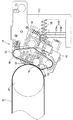
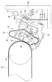
続いて、二次転写ユニット(転写装置)10の構成について具体的に説明する。図2に示すように、二次転写ユニット10は、二次転写ベルト50、二次転写ローラ52、駆動ローラ54、従動ローラ56、テンションローラ58およびバックアップローラ60を備える。二次転写ローラ52、駆動ローラ54、従動ローラ56、テンションローラ58およびバックアップローラ60のそれぞれは、二次転写フレーム62によって軸支される。
Next, the configuration of the secondary transfer unit (transfer device) 10 will be specifically described. As shown in FIG. 2, the
二次転写ベルト50は、二次転写ローラ52、駆動ローラ54、従動ローラ56、テンションローラ58およびバックアップローラ60に張架される無端帯状のベルトである。二次転写ベルト50は、中間転写ベルト32との間でニップ部70を形成し、駆動ローラ54の回転駆動に伴い、所定方向(図2では時計回り)に回転(周回移動)する。
The
駆動ローラ54は、図示しない駆動部によってその軸線回りに回転可能に設けられる。従動ローラ56およびテンションローラ58は、二次転写ベルト50の周回移動に伴って回転すると共に、二次転写ベルト50に一定の張力を与えて二次転写ベルト50の弛みを防止する。
The
二次転写ローラ52は、二次転写ベルト50を挟んで中間転写ベルト32に対向して配置される。二次転写ローラ52が二次転写ベルト50の内周面を押圧することにより、二次転写ベルト50の外周面と中間転写ベルト32の外周面とが所定圧で接触される。また、二次転写ローラ50には、図示しない転写電源が接続される。画像形成時には、この転写電源によって二次転写ローラ50に電圧(二次転写電圧)が印加される。これによって、ニップ部70に転写電界が形成され、この転写電界の作用によって、中間転写ベルト32の外周面に形成されたトナー像がニップ部70を通過する用紙に転写される。
The
また、バックアップローラ60は、二次転写ローラ52の用紙搬送方向における上流側において二次転写ベルト50を張架する。このバックアップローラ60は、ニップ部70の幅(用紙搬送方向の長さ)を拡張する機能を有し、これによって転写性が向上される。
Further, the
このような二次転写ユニット10は、上述のように、中間転写ベルト32に対する自身の配置位置を変位可能な変位機構を備える。この第1実施例では、二次転写ユニット10は、ユーザに手動操作されることによって、普通紙転写用の第1接触位置(図3参照)、厚紙等転写用の第2接触位置(図4参照)、および離間位置(図5参照)の3段階に変位可能とされる。
Such a
具体的には、二次転写ユニット10は、駆動ローラ54を支点(回転軸)として、つまり二次転写ローラ52を挟んでバックアップローラ60と反対側の部分を支点として、駆動ローラ54の軸回りに回転移動(揺動)可能な状態で、支持フレーム106によって支持される。また、支持フレーム106と二次転写フレーム62との間には、第1圧縮ばね108が設けられる。二次転写ユニット10は、この第1圧縮ばね108によって中間転写ベルト32側に向かって付勢される。
Specifically, the
また、支持フレーム106には、係止部110が設けられる。係止部110は、略直方体状に形成される第1係止部110aと第2係止部110bとを含む。第1係止部110aの高さは、第2係止部110bの高さよりも高くされ、係止部110の上端部は、ドアユニット104側(図2では右側)に向かって下り段差となる階段状に形成される。
The
一方、二次転写フレーム62には、二次転写ユニット10の配置位置を保持するための保持部材80が設けられる。保持部材80は、支持フレーム106の係止部110に係止されることによって、第1圧縮ばね108の付勢力に抗して二次転写ユニット10の配置位置を所望位置で保持する。
On the other hand, the
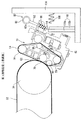
保持部材80は、図3からよく分かるように、円柱状に形成される軸部82を備える。軸部82の下端部には、係止部110に係止される突起部84が設けられ、軸部82の上端部には、リング状の把持部86が設けられる。保持部材80は、軸部82が二次転写フレーム62の上枠62aに形成された貫通孔に嵌め込まれることによって、上下方向に摺動可能とされる。この際、把持部86は、二次転写フレーム62の上枠62aから上方に突出した状態とされる。また、軸部82の外周面には、上枠62aと突起部84との間に第2圧縮ばね88が設けられており、この第2圧縮ばね88によって保持部材80は下方向に付勢される。
As can be clearly seen from FIG. 3, the holding
ユーザは、保持部材80の突起部84が係止部110に係止される位置を変更することによって、二次転写ユニット10の配置位置を、第1接触位置、第2接触位置および離間位置のいずれかに変位させることが可能である。
The user changes the position where the
ここで、二次転写ユニット10が第1接触位置にあるときには、保持部材80の突起部84が第1係止部110aの上面に載置される(図3参照)。この状態では、保持部材80は、第1圧縮ばね108の付勢力にほとんど影響を与えないので、第1圧縮ばね108の付勢力が二次転写ユニット10にそのまま作用して、二次転写ユニット10は第1接触位置で保持される。また、二次転写ユニット10が第2接触位置にあるときには、保持部材80の突起部84が第1係止部110aの上端部側面に係止される(図4参照)。つまり、保持部材80は、突起部84が第1係止部110aの上端部側面に係止されることによって、第1圧縮ばね108の付勢力に抗して二次転写ユニット10を第2接触位置で保持する。さらに、二次転写ユニット10が離間位置にあるときには、保持部材80の突起部84が第2係止部110bの上端部側面に係止される(図5参照)。つまり、保持部材80は、突起部84が第2係止部110bの上端部側面に係止されることによって、第1圧縮ばね108の付勢力に抗して二次転写ユニット10を離間位置で保持する。
Here, when the
二次転写ユニット10を第1接触位置側から離間位置側に変位させる際には、ユーザは、ドアユニット104を開いた後、たとえば二次転写フレーム62の両側を把持して、二次転写ユニット10をドアユニット104側に引き寄せる(或いは押し込む)とよい。二次転写ユニット10を筐体102のドアユニット104側に引き寄せると、第2圧縮ばね88の付勢力によって保持部材80は下方向に移動すると共に、係止部110に係止される突起部84の位置が変更される。これによって、二次転写ユニット10は、駆動ローラ54を支点としてその軸回りに回転移動し、その配置位置は、第1接触位置、第2接触位置および離間位置の順に変更される。
When displacing the
一方、二次転写ユニット10を離間位置側から第1接触位置側に変位させる際には、ユーザは、把持部86を把持して、保持部材80を上方に引っ張るとよい。保持部材80を持ち上げると、係止部110による突起部84の係止が解除されて、第1圧縮ばね108の付勢力によって二次転写ユニット10が中間転写ベルト32側に押し返される。これによって、二次転写ユニット10の配置位置は、離間位置、第2接触位置および第1接触位置の順に変更される。
On the other hand, when displacing the
なお、図示は省略するが、保持部材80には、二次転写ユニット10の配置位置をユーザに明示する目印を設けておくとよい。保持部材80は、二次転写ユニット10の配置位置に応じて上下方向の位置が変わるので、たとえば、軸部82の上端部に各配置位置を示す標線を設けておき、上枠62aの上面と各標線との一致する位置が、現在の二次転写ユニット10の配置位置を示すようにしておくとよい。これによって、ユーザは、二次転写ユニット10の現在の配置位置を容易に知ることができ、二次転写ユニット10を変位させる手動操作を間違えることなく実行できる。ただし、二次転写ユニット10の配置位置を検出する位置センサを設けておき、その検出結果を操作パネル(図示せず)等に表示することによって、二次転写ユニット10の現在の配置位置をユーザに知らせるようにすることもできる。
Although not shown, the holding
続いて、二次転写ユニット10の各配置位置における、二次転写ベルト50、二次転写ローラ52およびバックアップローラ60と中間転写ベルト32との位置関係について説明する。
Next, the positional relationship between the
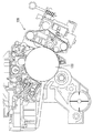
図3に示すように、第1接触位置は、普通紙に対して画像を形成するのに適した二次転写ユニット10の配置位置である。すなわち、第1接触位置では、普通紙の厚みやコシ等の規格に合わせて、ニップ部70の押圧力(ニップ圧)および幅(ニップ幅)が所定の値となるように、二次転写ユニット10の各部材の配置位置が設定されている。具体的には、第1接触位置では、二次転写ローラ52は、中間転写ベルト32と二次転写ベルト50とが第1所定圧で接触するように二次転写ベルト50を押圧する位置に配置される。また、バックアップローラ60は、他の配置位置と比較して、二次転写ベルト50を挟んで中間転写ベルト32に最も接近する位置に配置される。
As shown in FIG. 3, the first contact position is an arrangement position of the
なお、バックアップローラ60は、この第1接触位置(つまり中間転写ベルト32に最も接近する場合)において、二次転写ベルト50を挟んで中間転写ベルト32に接触するように配置することもできるが、二次転写ベルト50を挟んで中間転写ベルト32に接触しないように配置することが好ましい。これは、二次転写ベルト50を挟んで中間転写ベルト32に接触するようにバックアップローラ60を配置すると、二次転写ユニット10を変位させる際の位置決めがバックアップローラ60に影響されてしまい、位置決めの精度が悪くなってしまうからである。二次転写ベルト50を挟んで中間転写ベルト32に接触しないようにバックアップローラ60を配置することによって、中間転写ユニット22および二次転写ユニット10のフレーム同士で位置決めが可能となるので、二次転写ユニット10を変位させる際の位置決めの精度が向上する。
The
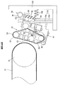
また、図4に示すように、第2接触位置は、厚紙等に対して画像を形成するのに適した二次転写ユニット10の配置位置である。すなわち、第2接触位置では、普通紙よりも厚みが大きくコシの強い厚紙等に対応させるため、第1接触位置よりも、ニップ部70の用紙突入口72が広げられると共に、ニップ部70の押圧力の値が小さくされる。具体的には、第2接触位置では、二次転写ローラ52は、中間転写ベルト32と二次転写ベルト50とが第1所定圧よりも小さい第2所定圧(たとえば、第1所定圧の半分の値)で接触するように二次転写ベルト50を押圧する位置に配置される。また、バックアップローラ60は、第1接触位置における位置よりも所定距離だけ中間転写ベルト32から離れた位置に配置され、たとえば、バックアップローラ60と中間転写ベルト32との距離が第1接触位置における距離の2倍となる位置に配置される。
Further, as shown in FIG. 4, the second contact position is an arrangement position of the
このように、ニップ部70の用紙突入口72を広げると共に、ニップ部70の押圧力を小さくすることで、普通紙よりも厚みが大きくコシの強い厚紙等であっても、ニップ部70に突入し易くなり、かつ、ニップ部70から抜け易くなる。つまり、厚紙等の先端がニップ部70に突入する際や厚紙等の後端がニップ部70から抜ける際の衝撃が低減されるので、転写画像ブレが抑制される。また、厚紙等の衝突によって二次転写ユニット10や中間転写ユニット22等にかかる負荷も低減される。
In this way, by expanding the
ここで、二次転写ユニット10の変位機構は、駆動ローラ54(つまり二次転写ローラ52を挟んでバックアップローラ60と反対側の部分)を支点として二次転写ユニット10を回転移動させることによって、二次転写ユニット10を第1接触位置と第2接触位置とに変位させる。このため、第1接触位置から第2接触位置への変位時には、支点に近い二次転写ローラ52の方が、バックアップローラ60よりも移動量が小さくなる。バックアップローラ60を少し大きめに移動させることで、ニップ部70の用紙突入口72が効果的に広げられ、二次転写ローラ52の移動量を抑えることで、ニップ部70の幅が小さくなることが抑制されて、転写性が保持される。すなわち、駆動ローラ54を支点として二次転写ユニット10が回転移動して変位することによって、ニップ部70の幅を保持しつつ、用紙突入口72を効果的に広げることができる。
Here, the displacement mechanism of the
図5に示すように、離間位置は、転写動作を長時間実施しない場合などに利用される二次転写ユニット10の配置位置である。離間位置では、二次転写ローラ52およびバックアップローラ60が中間転写ベルト32から大きく離れ、二次転写ベルト50は、中間転写ベルト32から完全に離間する。
As shown in FIG. 5, the separation position is an arrangement position of the
以上のように、この第1実施例によれば、普通紙に適した第1接触位置に加えて、第1接触位置よりもニップ部70の用紙突入口72が広くニップ圧が小さい第2接触位置に変位可能な変位機構を備えるので、コシの強い厚紙等に画像を形成する際の転写画像ブレを適切に抑制できる。
As described above, according to the first embodiment, in addition to the first contact position suitable for plain paper, the second contact where the
また、第1実施例によれば、二次転写ローラ52を挟んでバックアップローラ60と反対側の部分を支点として二次転写ユニット10を回転移動させて変位させるので、ニップ部70の幅を保持しつつ、用紙突入口72を効果的に広げることができる。
Further, according to the first embodiment, the
[第2実施例]
次に、図6および図7を参照して、この発明の第2実施例である二次転写ユニット10について説明する。この第2実施例では、ユーザによって手動操作される保持部材80を備える代わりに、自動的に二次転写ユニット10を変位させるためのカム機構を備える点が上述の第1実施例と異なる。その他の部分の構成については同様であるので、上述の第1実施例と共通する部分については、同じ参照番号を付し、重複する説明は省略または簡略化する。
[Second Embodiment]
Next, a
図6に示すように、二次転写フレーム62には、下方に突出する平板状の支持壁62bが設けられる。また、支持フレーム106と反対側の支持壁62bの側面に当接するように、カム90が設けられる。
As shown in FIG. 6, the
図7に示すように、カム90は、角丸三角形状の断面を有する。図示は省略するが、カム90には、駆動源からの回転力を伝達されることで回転する軸部材が接続され、この軸部材が回転することでカム90も回転する。カム90の回転中心90aは、偏心しており、回転中心90aから3つの外側平面P1,P2,P3までの距離は、それぞれ異なるようにされる。すなわち、回転中心90aから外側平面P2までの距離は、回転中心90aから外側平面P1までの距離よりも少し大きく設定され、回転中心90aから外側平面P3までの距離は、回転中心90aから外側平面P2までの距離よりもさらに大きく設定される。
As shown in FIG. 7, the
そして、カム90の外側平面P1が支持壁62bに当接する状態では、二次転写ユニット10は、普通紙転写用の第1接触位置に配置される。また、カム90が回転することによってカム90の外側平面P2が支持壁62bに当接する状態になると、カム90によって支持壁62bが押されて、二次転写ユニット10は、駆動ローラ54を支点としてその軸回りに回転移動して、厚紙等転写用の第2接触位置に配置される。同様に、カム90の外側平面P3が支持壁62bに当接する状態になると、二次転写ユニット10は、離間位置に配置される。
When the outer flat surface P1 of the
また、図示は省略するが、この第2実施例では、用紙の厚みに関する情報(厚み情報)を検出する厚み検出部を備える。厚み検出部としては、たとえば二次転写ベルト50よりも用紙搬送方向上流側に設けられる光センサが用いられ、用紙に対する光の反射率または透過率を測定することによって、用紙の厚みが検出される。ただし、厚み検出部による用紙の厚み検出方法は特に限定されず、たとえば、用紙を挟み込んだときの搬送ローラ40等の移動量を測定することによって、用紙の厚みを検出してもよい。また、たとえば、操作パネルに用紙の種類を選択するボタンを設けておき、ユーザによって選択された用紙の種類に基づいて用紙の厚みを検出することもできる。
Although not shown, the second embodiment includes a thickness detector that detects information (thickness information) related to the thickness of the paper. As the thickness detection unit, for example, an optical sensor provided upstream of the
画像形成装置10の制御部30は、厚み検出部によって検出された用紙の厚みに関する情報に基づいて、用紙が普通紙であるか厚紙等であるかを判定し、この判定結果に応じて、カム90を回転させて二次転写ユニット10の配置位置を変位させる。
The
この第2実施例によれば、第1実施例と同様に、普通紙に適した第1接触位置に加えて、第1接触位置よりもニップ部70の用紙突入口72が広くニップ圧が小さい第2接触位置に変位可能な変位機構を備えるので、コシの強い厚紙等に画像を形成する際の転写画像ブレを適切に抑制できる。
According to the second embodiment, as in the first embodiment, in addition to the first contact position suitable for plain paper, the
また、第2実施例によれば、用紙の厚みに応じて自動的に二次転写ユニット10の配置位置が変位されるので、ユーザの操作負担が低減される。
Further, according to the second embodiment, since the arrangement position of the
[第3実施例]
続いて、図8を参照して、この発明の第3実施例である二次転写ユニット10について説明する。この第3実施例では、厚紙等転写用として第2接触位置および第3接触位置の2段階に変位可能とされ、二次転写ユニット10が計4段階で変位される点が、上述の第1実施例と異なる。その他の部分の構成については同様であるので、上述の第1実施例と共通する部分については、同じ参照番号を付し、重複する説明は省略または簡略化する。ただし、第3実施例においても、二次転写ユニット10の変位機構として、第2実施例のようにカム機構を用いてもよい。
[Third embodiment]
Next, a
図8に示すように、支持フレーム106には、係止部110が設けられる。この第3実施例では、係止部110は、略直方体状に形成される第1係止部110a、第2係止部110b、および第3係止部110cを含む。第1係止部110aの高さは、第2係止部110bの高さよりも高く、また、第2係止部110bの高さは、第3係止部110cの高さよりも高くされる。つまり、係止部110の上端部は、ドアユニット104側(図8では右側)に向かって下り段差となる階段状に形成される。
As shown in FIG. 8, the
ここで、二次転写ユニット10が第1接触位置にあるときには、保持部材80の突起部84が第1係止部110aの上面に載置される。また、二次転写ユニット10が第2接触位置にあるときには、保持部材80の突起部84が第1係止部110aの上端部側面に係止される。さらに、二次転写ユニット10が第3接触位置にあるときには、保持部材80の突起部84が第2係止部110bの上端部側面に係止される。さらにまた、二次転写ユニット10が離間位置にあるときには、保持部材80の突起部84が第3係止部110cの上端部側面に係止される。
Here, when the
上述のように、第2接触位置および第3接触位置は、厚紙等に対して画像を形成するのに適した二次転写ユニット10の配置位置である。すなわち、第2接触位置では、普通紙よりも厚みが大きくコシの強い厚紙等に対応させるため、第1接触位置よりも、ニップ部70の用紙突入口72が広げられると共に、ニップ部70の押圧力の値が小さくされる。また、第3接触位置では、より厚みが大きくコシの強い厚紙等に対応させるため、第2接触位置よりも、ニップ部70の用紙突入口72が広げられると共に、ニップ部70の押圧力の値が小さくされる。
As described above, the second contact position and the third contact position are positions where the
この第3実施例によれば、厚紙等に適した配置位置として第2接触位置および第3接触位置の2段階に変位可能な変位機構を備えるので、複数種類の厚みに対応可能となり、コシの強い厚紙等に画像を形成する際の転写画像ブレをより適切に抑制できる。 According to the third embodiment, since the displacement mechanism that can be displaced in two stages of the second contact position and the third contact position is provided as an arrangement position suitable for thick paper or the like, it is possible to cope with a plurality of types of thickness, Transfer image blurring when forming an image on strong cardboard or the like can be more appropriately suppressed.
なお、第3実施例では、厚紙等転写用として第2接触位置および第3接触位置の2段階に二次転写ユニット10を変位可能としたが、二次転写ユニット10は、厚紙等転写用として3段階以上に変位可能とすることもできる。
In the third embodiment, the
なお、上述の各実施例では、二次転写ユニット(転写装置)10を離間位置に変位可能としたが、二次転写ユニット10は、必ずしも離間位置に変位可能とされる必要はない。
In each of the above-described embodiments, the secondary transfer unit (transfer device) 10 can be displaced to the separation position, but the
また、上述の各実施例では、二次転写ベルト50を挟んで中間転写ベルト32と接触する位置に二次転写ローラ52を配置しているが、二次転写ローラ52は、必ずしも二次転写ベルト50を挟んで中間転写ベルト32に接触している必要はなく、たとえば、図2等に示す位置よりも用紙搬送方向における下流側に二次転写ローラ52が配置されても構わない。
In each of the above-described embodiments, the
さらに、上述の各実施例では、駆動ローラ54を支点(回転軸)として二次転写ユニット10を回転移動させて変位させたが、二次転写ユニット10を回転移動させる際の支点は、特に限定されない。たとえば、テンションローラ58を支点として二次転写ユニット10を回転移動させることもできる。
Further, in each of the above-described embodiments, the
また、二次転写ユニット10の全体を回転移動させて変位させる代わりに、或いは回転移動させると共に、二次転写ユニット10の全体を水平移動させて変位させることもできる。また、二次転写ローラ52およびバックアップローラ60を個別に変位させることによって、二次転写ユニット10を変位させることも可能である。
Further, instead of rotating the entire
さらにまた、上述の各実施例では、像担持体に形成されたトナー像を用紙に転写する転写装置として二次転写ユニット10を例示したが、これに限定されない。この発明に係る転写装置は、たとえば、図9に示すように、像担持体である感光体ドラム122(感光体ベルトでもよい)に形成されたトナー像を用紙に直接転写する転写ユニット120であってもよい。
Furthermore, in each of the above-described embodiments, the
なお、上で挙げた寸法などの具体的数値は、いずれも単なる一例であり、製品の仕様などの必要に応じて適宜変更可能である。 It should be noted that the specific numerical values such as the dimensions mentioned above are merely examples, and can be appropriately changed according to the needs of product specifications and the like.
10 …二次転写ユニット(転写装置)
12 …感光体ドラム
22 …中間転写ユニット
30 …制御部
32 …中間転写ベルト(像担持体)
34 …駆動ローラ
50 …二次転写ベルト(転写ベルト)
52 …二次転写ローラ(転写ローラ)
60 …バックアップローラ
80 …保持部材
90 …カム
100 …画像形成装置
104 …ドアユニット
106 …支持フレーム
108 …第1圧縮ばね
110 …係止部
120 …転写ユニット(転写装置)
122 …感光体ドラム(像担持体)
10 ... Secondary transfer unit (transfer device)
DESCRIPTION OF
34: Driving roller 50: Secondary transfer belt (transfer belt)
52 ... Secondary transfer roller (transfer roller)
DESCRIPTION OF
122... Photoconductor drum (image carrier)
Claims (6)
複数のローラによって周回移動可能に張架され、前記像担持体との間でニップ部を形成する転写ベルト、
前記転写ベルトを挟んで前記像担持体に対向して配置され、前記ニップ部に転写電界を形成する転写ローラ、
前記転写ローラの用紙搬送方向における上流側において前記転写ベルトを張架するバックアップローラ、および
前記像担持体に対する前記転写装置の配置位置を少なくとも第1接触位置と第2接触位置とに変位可能な変位機構を備え、
前記第1接触位置は、前記像担持体と前記転写ベルトとが第1所定圧で接触するように前記転写ローラが当該転写ベルトを押圧し、かつ前記バックアップローラが前記像担持体に最も接近する位置であり、
前記第2接触位置は、前記像担持体と前記転写ベルトとが前記第1所定圧より小さい第2所定圧で接触するように前記転写ローラが当該転写ベルトを押圧し、かつ前記バックアップローラが前記第1接触位置における位置よりも所定距離だけ前記像担持体から離れる位置であって、
前記変位機構は、上端部が段差状に形成される係止部と、前記係止部の上端部に係止されることによって、前記転写装置の配置位置を所望位置で保持する保持部材とを含む、転写装置。 A transfer device for transferring a toner image formed on an image carrier to paper,
A transfer belt that is stretched by a plurality of rollers so as to be able to move around and forms a nip portion with the image carrier;
A transfer roller disposed opposite to the image carrier with the transfer belt interposed therebetween, and forming a transfer electric field in the nip portion;
A back-up roller that stretches the transfer belt on the upstream side in the paper transport direction of the transfer roller, and a displacement that can displace the transfer device relative to the image carrier to at least a first contact position and a second contact position. Equipped with a mechanism
The first contact position is such that the transfer roller presses the transfer belt so that the image carrier and the transfer belt are in contact with each other at a first predetermined pressure, and the backup roller is closest to the image carrier. Position,
The second contact position is such that the transfer roller presses the transfer belt so that the image carrier and the transfer belt are in contact with each other at a second predetermined pressure smaller than the first predetermined pressure, and the backup roller is What position der away from the image bearing member by a predetermined distance than the position in the first contact position,
The displacement mechanism includes an engaging portion having an upper end portion formed in a step shape, and a holding member that holds the arrangement position of the transfer device at a desired position by being engaged with the upper end portion of the engaging portion. Including a transfer device.
Priority Applications (1)
| Application Number | Priority Date | Filing Date | Title |
|---|---|---|---|
| JP2014184743A JP6326331B2 (en) | 2014-09-11 | 2014-09-11 | Transfer device and image forming apparatus having the same |
Applications Claiming Priority (1)
| Application Number | Priority Date | Filing Date | Title |
|---|---|---|---|
| JP2014184743A JP6326331B2 (en) | 2014-09-11 | 2014-09-11 | Transfer device and image forming apparatus having the same |
Publications (2)
| Publication Number | Publication Date |
|---|---|
| JP2016057514A JP2016057514A (en) | 2016-04-21 |
| JP6326331B2 true JP6326331B2 (en) | 2018-05-16 |
Family
ID=55758378
Family Applications (1)
| Application Number | Title | Priority Date | Filing Date |
|---|---|---|---|
| JP2014184743A Active JP6326331B2 (en) | 2014-09-11 | 2014-09-11 | Transfer device and image forming apparatus having the same |
Country Status (1)
| Country | Link |
|---|---|
| JP (1) | JP6326331B2 (en) |
Families Citing this family (2)
| Publication number | Priority date | Publication date | Assignee | Title |
|---|---|---|---|---|
| JP6977263B2 (en) * | 2017-01-18 | 2021-12-08 | 富士フイルムビジネスイノベーション株式会社 | Transfer device and image forming device |
| JP7558657B2 (en) | 2020-01-22 | 2024-10-01 | キヤノン株式会社 | Image forming device |
Family Cites Families (6)
| Publication number | Priority date | Publication date | Assignee | Title |
|---|---|---|---|---|
| JP3303220B2 (en) * | 1993-12-06 | 2002-07-15 | 京セラミタ株式会社 | Transfer device for image generator |
| JP3472947B2 (en) * | 1995-08-24 | 2003-12-02 | 京セラミタ株式会社 | Transfer device of image forming machine |
| US5983060A (en) * | 1997-03-31 | 1999-11-09 | Ricoh Company, Ltd. | Image forming apparatus which removes a surface potential of an intermediate transfer member |
| JP2004205871A (en) * | 2002-12-26 | 2004-07-22 | Canon Inc | Image forming device |
| JP2005003935A (en) * | 2003-06-12 | 2005-01-06 | Canon Inc | Image forming apparatus |
| JP2007164038A (en) * | 2005-12-16 | 2007-06-28 | Konica Minolta Business Technologies Inc | Image forming apparatus |
-
2014
- 2014-09-11 JP JP2014184743A patent/JP6326331B2/en active Active
Also Published As
| Publication number | Publication date |
|---|---|
| JP2016057514A (en) | 2016-04-21 |
Similar Documents
| Publication | Publication Date | Title |
|---|---|---|
| JP5696460B2 (en) | Sheet feeding apparatus and image forming apparatus | |
| JP6180253B2 (en) | Image forming apparatus | |
| JP4932347B2 (en) | Transfer device and image forming apparatus | |
| JP2014015335A (en) | Sheet material position correction device and image forming apparatus | |
| US8417165B2 (en) | Image forming apparatus | |
| JP6326331B2 (en) | Transfer device and image forming apparatus having the same | |
| JP2013171175A (en) | Rotary drive device, rotary drive control method, and image formation apparatus | |
| JP2012163730A (en) | Image forming apparatus | |
| JP5618585B2 (en) | Image forming apparatus | |
| JP2015105969A (en) | Image forming apparatus | |
| JP5165077B2 (en) | Displacement mechanism of secondary transfer unit and image forming apparatus | |
| JP6032471B2 (en) | Image forming apparatus | |
| US20140062011A1 (en) | Sheet conveying apparatus and image forming apparatus | |
| JP2016057455A (en) | Image forming apparatus | |
| JP2016090654A (en) | Image forming apparatus and image forming system | |
| JP6061190B2 (en) | Belt misalignment correction mechanism, belt device, transfer belt device, and image forming apparatus | |
| JP2017016072A (en) | Image forming apparatus | |
| JP5054557B2 (en) | Fixing device and image forming apparatus having the same | |
| JP2015060030A (en) | Image forming apparatus | |
| JP2010070288A (en) | Paper sheet conveying device, image forming device, paper sheet conveyance control method, and computer program | |
| JP2009128811A (en) | Image forming apparatus | |
| JP3819410B2 (en) | Image forming apparatus | |
| JP2004264454A (en) | Image forming device | |
| JP2009137710A (en) | Sheet conveying apparatus, sheet conveying method, and image forming apparatus | |
| JP2007309954A (en) | Rotary cam mechanism and image forming apparatus provided therewith |
Legal Events
| Date | Code | Title | Description |
|---|---|---|---|
| A621 | Written request for application examination |
Free format text: JAPANESE INTERMEDIATE CODE: A621 Effective date: 20170403 |
|
| A977 | Report on retrieval |
Free format text: JAPANESE INTERMEDIATE CODE: A971007 Effective date: 20171115 |
|
| A131 | Notification of reasons for refusal |
Free format text: JAPANESE INTERMEDIATE CODE: A131 Effective date: 20171121 |
|
| A521 | Written amendment |
Free format text: JAPANESE INTERMEDIATE CODE: A523 Effective date: 20180118 |
|
| TRDD | Decision of grant or rejection written | ||
| A01 | Written decision to grant a patent or to grant a registration (utility model) |
Free format text: JAPANESE INTERMEDIATE CODE: A01 Effective date: 20180403 |
|
| A61 | First payment of annual fees (during grant procedure) |
Free format text: JAPANESE INTERMEDIATE CODE: A61 Effective date: 20180416 |
|
| R150 | Certificate of patent or registration of utility model |
Ref document number: 6326331 Country of ref document: JP Free format text: JAPANESE INTERMEDIATE CODE: R150 |