EP2466210A2 - Household appliance with a front panel having means for fixing knob holders - Google Patents
Household appliance with a front panel having means for fixing knob holders Download PDFInfo
- Publication number
- EP2466210A2 EP2466210A2 EP11193904A EP11193904A EP2466210A2 EP 2466210 A2 EP2466210 A2 EP 2466210A2 EP 11193904 A EP11193904 A EP 11193904A EP 11193904 A EP11193904 A EP 11193904A EP 2466210 A2 EP2466210 A2 EP 2466210A2
- Authority
- EP
- European Patent Office
- Prior art keywords
- knob
- control panel
- household appliance
- ridge
- appliance according
- Prior art date
- Legal status (The legal status is an assumption and is not a legal conclusion. Google has not performed a legal analysis and makes no representation as to the accuracy of the status listed.)
- Granted
Links
Images



Classifications
-
- F—MECHANICAL ENGINEERING; LIGHTING; HEATING; WEAPONS; BLASTING
- F24—HEATING; RANGES; VENTILATING
- F24C—DOMESTIC STOVES OR RANGES ; DETAILS OF DOMESTIC STOVES OR RANGES, OF GENERAL APPLICATION
- F24C7/00—Stoves or ranges heated by electric energy
- F24C7/08—Arrangement or mounting of control or safety devices
- F24C7/082—Arrangement or mounting of control or safety devices on ranges, e.g. control panels, illumination
-
- G—PHYSICS
- G05—CONTROLLING; REGULATING
- G05G—CONTROL DEVICES OR SYSTEMS INSOFAR AS CHARACTERISED BY MECHANICAL FEATURES ONLY
- G05G1/00—Controlling members, e.g. knobs or handles; Assemblies or arrangements thereof; Indicating position of controlling members
- G05G1/08—Controlling members for hand actuation by rotary movement, e.g. hand wheels
- G05G1/087—Controlling members for hand actuation by rotary movement, e.g. hand wheels retractable; Flush control knobs
Definitions
- the present invention relates to a household appliance with an improved control panel, and more particularly the invention is pertaining to a household appliance having a front control panel adapted for holding and fixing of the knob holders.
- Control knobs especially the pop-out type control knobs employed in the conventional household appliances are generally placed and operated in individual hollow housings that are mounted right onto the rear side of a secondary panel.
- the hollow housing also known as knob holder, has corresponding fixing means for secure attachment to the secondary panel.
- FIG. 1 there is shown a conventional arrangement of prior art as referred above wherein a number of knob holders are attached to a secondary panel by means of various fixing elements such as the grooves and additional supporting means adapted to prevent unintentional rotation and separation of said knob holder.
- the secondary panel attached with the knob holders is then affixed to the front panel by means of a double-sided self adhesive tape as shown in Figure 2 .
- This conventional arrangement with three components is mainly adopted for providing a front panel having a uniform surface without any tracing or unenviable viewing of the fixing elements and knob holders.
- DE-C1-10044448 discloses a rotary switch arrangement for a household appliance wherein the hollow body of the knob holder is provided with elongated legs that engages to the upper and lower most vicinity of the front panel.
- a further object of the present invention is to provide a household appliance having a knob holder engagement directly to the front panel wherein fixing elements are occupying less space as compared to the known elements of the conventional knob holders and control panels.
- the present invention aims to solve the aforementioned technical problems by way of providing a novel household appliance comprising a number of control knobs on a control panel having knob openings and corresponding knob holders having a hollow body for securely holding and fixing of said knobs.
- the knob holders and front control panel of the invention are adapted directly to engage each other without auxiliary fixing means.
- control panel comprises an inwardly arranged integral ridge in the circumferential vicinity of each knob opening wherein each ridge comprises at least one clamping slot arranged in perpendicular direction to the control panel.
- the knob holders provided according to the present invention are characterized by a latching device having a tip portion arranged to be fixedly engaged with the slot when the knob holder abuts to the circumferential area of said ridge.
- the household appliance (not shown) according to the present invention comprises a control panel (20) which is generally in the form of a front panel as conventionally known in the prior art arrangements, and comprising a number of knob holders (10) for securely holding corresponding knobs, particularly pop-out type knobs (not shown).
- Figure 3 shows a rear perspective view of the control panel arrangement according to the present invention wherein the knob holders (10), that are substantially in the form of a cylindrical hollow body, and the control panel (20) are adapted directly to engage to each other without auxiliary fixing elements and adhesive materials.
- control panel (20) of the present invention is provided with inwardly arranged ridges (24) in the circumferential vicinity of the knob openings (26) wherein the each ridge (24) arranged in a manner as above is formed integrally with the control panel body (20) by way of, for instance inwardly bending the material of said control panel (20) with a bending process involving conventional bending machinery.
- Each ridge (24) according to the present invention comprises at least one clamping slot (25) preferably in the form of a slit. Said slot (25) is arranged in perpendicular direction to the control panel (20) for engaging to the knob holder (10).
- This arrangement according to the present invention preferably comprises at least two slots (25), and more preferably three slots (25) as shown in Figure 3 .
- the slot (25) as referred above according to the invention is provided on a protrusion (22) that protrudes from the ridge (24).
- Said protrusion (22) is arranged in perpendicular direction relative to the control panel (20) (parallel to the knob holder (10)) so that the knob holder (10) may easily engage with it.
- the arrangement of the invention preferably comprises same number of protrusions (22) as the slots (25).
- the knob holders (10) of the present invention comprise corresponding latching devices (16) having an inwardly bending tip portion (11) adapted to engage and lock with the slot (25) as shown in Figures 5 to 7 .
- a detail (C) of the locking section shown in Figure 7 is magnified and shown again in Figure 8 for better illustration of the locking relation in-between the tip portion (11) of the latching device (16) and said slot (25). Accordingly, the tip portion (11) is adapted to lock with the slot (25) with its protruded structure.
- the ridges (24) formed in the vicinity of the knob openings (26) are bended as an arc with a radius (R1) as shown in the detail (C) of Figure 8 .
- the inventors report that best results for obtaining a durable ridge (24) is obtained when said radius is substantially equal to the thickness of the metal sheet constituting the control panel (20).
- the knob holder (10) is adapted tightly to surround the ridge (24) portion by suitably adjusting its inside diameter (R2).
- the knob holder's (10) contact surfaces with the control panel (20) are provided with an inclination (15) having a toleration angle for tolerating the arc shaped bending corner of the ridges (24), and eventually perfect abutting onto the control panel surface is obtained.
- the perfect abutting of the knob holder (10) with the integral ridges (24), and also of the tight engagement between the slots (25) and latching devices (16) according to the invention no visual defects occur in the frontal view of the control panel as shown in Figure 4 .
- each protrusion (22) as provided on the ridge (24) has arc shaped front corners (27) and also arc shaped smooth connection corners (28) for eliminating sharpness and improving durability.
- the latching devices (16) formed on the knob holder (10) of the invention are formed by U shaped incision which provides a flexible structure permitting easier engagement and disengagement of the tip portion (11) to/from slot (25) of the ridge (24).
- the positions of the latching devices (16) on the knob holder (10) are arranged such that when said knob holder (10) is put in place and permitted to abut the circumferential area of the ridges (24), the tip portion (11) of the latching device (16) immediately engages to the slit opening of the slot (25).
- the knob holder (10) is eliminated of the unintentional rotation caused by rotation of the knob.
- more protrusions (22) may be provided for strengthening the engagement of the knob holder (10) as may be appreciated by those skilled in the technical field.
Landscapes
- Engineering & Computer Science (AREA)
- Chemical & Material Sciences (AREA)
- Combustion & Propulsion (AREA)
- Mechanical Engineering (AREA)
- General Engineering & Computer Science (AREA)
- Mechanical Control Devices (AREA)
- Cookers (AREA)
- Switch Cases, Indication, And Locking (AREA)
Abstract
Description
- The present invention relates to a household appliance with an improved control panel, and more particularly the invention is pertaining to a household appliance having a front control panel adapted for holding and fixing of the knob holders.
- Control knobs, especially the pop-out type control knobs employed in the conventional household appliances are generally placed and operated in individual hollow housings that are mounted right onto the rear side of a secondary panel. The hollow housing, also known as knob holder, has corresponding fixing means for secure attachment to the secondary panel.
- With reference to
Figure 1 , there is shown a conventional arrangement of prior art as referred above wherein a number of knob holders are attached to a secondary panel by means of various fixing elements such as the grooves and additional supporting means adapted to prevent unintentional rotation and separation of said knob holder. The secondary panel attached with the knob holders is then affixed to the front panel by means of a double-sided self adhesive tape as shown inFigure 2 . This conventional arrangement with three components is mainly adopted for providing a front panel having a uniform surface without any tracing or unenviable viewing of the fixing elements and knob holders. - Different attempts in the prior art have been exerted on providing alternative arrangements for modifying the aforementioned system and improving the knob holder connections.
DE-C1-10044448 discloses a rotary switch arrangement for a household appliance wherein the hollow body of the knob holder is provided with elongated legs that engages to the upper and lower most vicinity of the front panel. - This and other arrangements of the prior art, however disadvantageously require space occupying additional fixing elements which are not comfortable to be used in such a limited backward area of the front panels, and are generally complicated with multiple components involving, for instance front and secondary panels along with adhesion means.
- Therefore, there is still a long felt need for household appliances that involve simplified knob holder connections for providing the advantages expressed above. Thus, it is one of the objectives of the present invention to provide a household appliance that eliminates conventional multicomponent arrangements of the control panels employed in the prior art. A further object of the present invention is to provide a household appliance having a knob holder engagement directly to the front panel wherein fixing elements are occupying less space as compared to the known elements of the conventional knob holders and control panels. These objects have been achieved through a household appliance as disclosed in claim 1.
- The present invention aims to solve the aforementioned technical problems by way of providing a novel household appliance comprising a number of control knobs on a control panel having knob openings and corresponding knob holders having a hollow body for securely holding and fixing of said knobs. According to the arrangement of the present invention, the knob holders and front control panel of the invention are adapted directly to engage each other without auxiliary fixing means.
- Accordingly the control panel comprises an inwardly arranged integral ridge in the circumferential vicinity of each knob opening wherein each ridge comprises at least one clamping slot arranged in perpendicular direction to the control panel. The knob holders provided according to the present invention are characterized by a latching device having a tip portion arranged to be fixedly engaged with the slot when the knob holder abuts to the circumferential area of said ridge.
- The attached drawings are solely for illustrating a preferred embodiment of the invention and in no way limiting the scope of the appended claims, wherein;
-
Figure 1 shows an exploded demonstration of a prior art control panel with a number of knob holders. -
Figure 2 is a perspective view of the conventional control panel arrangement ofFig. 1 in mounted form. -
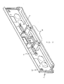
Figure 3 is a rear perspective view of the control panel of a household appliance according to the present invention. -
Figure 4 is sectional front view of the control panel used in the household appliance according to the present invention. -
Figure 5 shows a cross-sectional view of the knob holder in engaged position according to the present invention. -
Figure 6 is another cross-sectional view of the knob holder in engaged position according to the present invention. -
Figure 7 shows a further cross-sectional view of the knob holder in engaged position according to the present invention. -
Figure 8 is a magnified view of a detail (C) obtained from the connection area of knob holder and control panel according to the present invention. -
Figure 9 shows the knob holder and fixing means of the control panel in demounted position. - The household appliance (not shown) according to the present invention comprises a control panel (20) which is generally in the form of a front panel as conventionally known in the prior art arrangements, and comprising a number of knob holders (10) for securely holding corresponding knobs, particularly pop-out type knobs (not shown).
Figure 3 shows a rear perspective view of the control panel arrangement according to the present invention wherein the knob holders (10), that are substantially in the form of a cylindrical hollow body, and the control panel (20) are adapted directly to engage to each other without auxiliary fixing elements and adhesive materials. - For achieving this object, control panel (20) of the present invention is provided with inwardly arranged ridges (24) in the circumferential vicinity of the knob openings (26) wherein the each ridge (24) arranged in a manner as above is formed integrally with the control panel body (20) by way of, for instance inwardly bending the material of said control panel (20) with a bending process involving conventional bending machinery. Each ridge (24) according to the present invention comprises at least one clamping slot (25) preferably in the form of a slit. Said slot (25) is arranged in perpendicular direction to the control panel (20) for engaging to the knob holder (10). This arrangement according to the present invention preferably comprises at least two slots (25), and more preferably three slots (25) as shown in
Figure 3 . - In a preferred embodiment, the slot (25) as referred above according to the invention is provided on a protrusion (22) that protrudes from the ridge (24). Said protrusion (22) is arranged in perpendicular direction relative to the control panel (20) (parallel to the knob holder (10)) so that the knob holder (10) may easily engage with it. The arrangement of the invention preferably comprises same number of protrusions (22) as the slots (25).
- In accordance with the above arrangement, the knob holders (10) of the present invention comprise corresponding latching devices (16) having an inwardly bending tip portion (11) adapted to engage and lock with the slot (25) as shown in
Figures 5 to 7 . A detail (C) of the locking section shown inFigure 7 is magnified and shown again inFigure 8 for better illustration of the locking relation in-between the tip portion (11) of the latching device (16) and said slot (25). Accordingly, the tip portion (11) is adapted to lock with the slot (25) with its protruded structure. - According to a preferred embodiment, the ridges (24) formed in the vicinity of the knob openings (26) are bended as an arc with a radius (R1) as shown in the detail (C) of
Figure 8 . The inventors report that best results for obtaining a durable ridge (24) is obtained when said radius is substantially equal to the thickness of the metal sheet constituting the control panel (20). The knob holder (10) is adapted tightly to surround the ridge (24) portion by suitably adjusting its inside diameter (R2). Thus, in this preferred embodiment, the knob holder's (10) contact surfaces with the control panel (20) are provided with an inclination (15) having a toleration angle for tolerating the arc shaped bending corner of the ridges (24), and eventually perfect abutting onto the control panel surface is obtained. Hence, by virtue of the perfect abutting of the knob holder (10) with the integral ridges (24), and also of the tight engagement between the slots (25) and latching devices (16) according to the invention, no visual defects occur in the frontal view of the control panel as shown inFigure 4 . - Referring now to a further preferred embodiment as shown in
Figure 9 , wherein a connection section of the control panel (20) and knob holder (10) are shown in demounted form, each protrusion (22) as provided on the ridge (24) has arc shaped front corners (27) and also arc shaped smooth connection corners (28) for eliminating sharpness and improving durability. - In this preferred embodiment, the latching devices (16) formed on the knob holder (10) of the invention are formed by U shaped incision which provides a flexible structure permitting easier engagement and disengagement of the tip portion (11) to/from slot (25) of the ridge (24). The positions of the latching devices (16) on the knob holder (10) are arranged such that when said knob holder (10) is put in place and permitted to abut the circumferential area of the ridges (24), the tip portion (11) of the latching device (16) immediately engages to the slit opening of the slot (25).
- In a preferred embodiment where at least two, more preferably three protrusions (22) are provided on the ridges (24), the knob holder (10) is eliminated of the unintentional rotation caused by rotation of the knob. However, more protrusions (22) may be provided for strengthening the engagement of the knob holder (10) as may be appreciated by those skilled in the technical field.
-
- (10)
- Knob holder
- (11)
- Tip portion
- (15)
- Inclination
- (16)
- Latching device
- (20)
- Control Panel
- (22)
- Clamping protrusion
- (24)
- Ridge
- (25)
- Clamping slot
- (26)
- Knob opening
- (27)
- Front corner of the protrusion
- (28)
- Connection corner of the protrusion
- (R1)
- Radius of the arc
- (R2)
- Inner diameter of the knob holder
Claims (11)
- A household appliance comprising a number of control knobs on a control panel (20), said control panel (20) having knob openings (26) and corresponding knob holders (10) having a hollow body for securely holding and fixing of said knobs, characterized in that, the control panel (20) further comprises an inwardly arranged integral ridge (24) in the circumferential vicinity of each knob opening (26) wherein each ridge (24) comprises at least one clamping slot (25) arranged in perpendicular direction to the control panel (20), and in that, the knob holder (10) comprises a latching device (16) having a tip portion (11) arranged to be fixedly engaged with the slot (25) when the knob holder (10) abuts to the circumferential area of said ridge (24).
- A household appliance according to claim 1 wherein each ridge (24) comprises three clamping slots (25) whereas each knob holder (10) comprises latching devices (16) corresponding thereto.
- A household appliance according to claim 1 or 2 wherein said ridge (24) comprises protrusions (22) bearing the clamping slots (25).
- A household appliance according to one of the preceding claims 1 to 3, wherein the control knobs are pop-out type control knobs.
- A household appliance according to one of the preceding claims 1 to 4, wherein the control panel (20) is made of a metallic sheet material.
- A household appliance according to one of the preceding claims 1 to 5, wherein inwardly arranged ridge (24) is having an arc shaped bending corner with a radius (R1).
- A household appliance according to claim 6 wherein said radius (R1) is equal to the thickness of the metallic sheet material.
- A household appliance according to one of the preceding claims 1 to 7, wherein abutting surface of the knob holder (10) that is placed in contact with the control panel (20) is provided with an inclination (15) having a toleration angle for tolerating the arc shaped bending corner of the ridge (24).
- A household appliance according to one of the preceding claims 3 to 8, wherein the protrusions (22) comprises arc shaped front corners (27) and connection corners (28).
- A method for producing a household appliance comprising the steps of:- providing a control panel (20),- forming a number of knob openings (26) on said control panel (20), and bending the circumferential area of each knob opening (26) in order to form an inwardly arranged integral ridge (24) in the circumferential vicinity of said knob opening (26),- forming at least one clamping slot (25) on said ridge (24), the slot (25) being arranged in perpendicular direction to the control panel (20),- providing a number of knob holders (10), each comprising a latching device (16) having a tip portion (11) arranged to be fixedly engaged with the slot (25) of said ridge (24),- placing said knob holder (10) onto the control panel (20), and mounting so formed control panel (20) onto a household appliance.
- A method according to claim 10 wherein the method further comprises forming of at least one protrusion (22) and forming said clamping slot (25) on said protrusion (22).
Priority Applications (1)
| Application Number | Priority Date | Filing Date | Title |
|---|---|---|---|
| PL11193904T PL2466210T3 (en) | 2010-12-20 | 2011-12-16 | Household appliance with a front panel having means for fixing knob holders |
Applications Claiming Priority (1)
| Application Number | Priority Date | Filing Date | Title |
|---|---|---|---|
| TR2010/10611A TR201010611A2 (en) | 2010-12-20 | 2010-12-20 | HOUSEHOLD APPLIANCE WITH A FRONT PANEL WITH CRAFTS FOR FIXING BUTTON HOLDERS |
Publications (3)
| Publication Number | Publication Date |
|---|---|
| EP2466210A2 true EP2466210A2 (en) | 2012-06-20 |
| EP2466210A3 EP2466210A3 (en) | 2013-02-20 |
| EP2466210B1 EP2466210B1 (en) | 2016-10-26 |
Family
ID=45440189
Family Applications (1)
| Application Number | Title | Priority Date | Filing Date |
|---|---|---|---|
| EP11193904.7A Active EP2466210B1 (en) | 2010-12-20 | 2011-12-16 | Household appliance with a front panel having means for fixing knob holders |
Country Status (3)
| Country | Link |
|---|---|
| EP (1) | EP2466210B1 (en) |
| PL (1) | PL2466210T3 (en) |
| TR (1) | TR201010611A2 (en) |
Cited By (1)
| Publication number | Priority date | Publication date | Assignee | Title |
|---|---|---|---|---|
| WO2016138917A1 (en) * | 2015-03-02 | 2016-09-09 | Arcelik Anonim Sirketi | Cooking appliance with an improved control panel |
Families Citing this family (1)
| Publication number | Priority date | Publication date | Assignee | Title |
|---|---|---|---|---|
| TR201110708A2 (en) | 2011-10-27 | 2013-05-21 | Bsh Ev Aletleri San Ve Tic As | A Cooking Device Containing a Faucet Shaft Fastener |
Citations (1)
| Publication number | Priority date | Publication date | Assignee | Title |
|---|---|---|---|---|
| DE10044448C1 (en) | 2000-09-08 | 2002-01-24 | Bsh Bosch Siemens Hausgeraete | Rotary switch for domestic appliance has operating shaft provided with rotary switch knob supported from appliance control panel via bearing device |
Family Cites Families (5)
| Publication number | Priority date | Publication date | Assignee | Title |
|---|---|---|---|---|
| TR200800140T1 (en) * | 2005-07-25 | 2008-12-22 | Arçeli̇k Anoni̇m Şi̇rketi̇ | A home appliance. |
| DE102005035464A1 (en) * | 2005-07-28 | 2007-02-01 | BSH Bosch und Siemens Hausgeräte GmbH | Home appliance control device |
| DE102006039196B3 (en) * | 2006-08-22 | 2007-10-11 | Miele & Cie. Kg | Depressable operating element for domestic appliance with shaft for coupling to control element has bearing whose second surface of second part interacts in force transferring manner with shaft independently of a back plate |
| WO2010003216A1 (en) * | 2008-07-09 | 2010-01-14 | Omron Dualtec Automotive Electronics Inc. | Switch attachment assembly |
| ES1069404Y (en) * | 2008-12-18 | 2009-06-18 | Simon Sa | DEVICE FOR FIXING ELECTRICAL MECHANISMS ON THE FRAME-FRAME |
-
2010
- 2010-12-20 TR TR2010/10611A patent/TR201010611A2/en unknown
-
2011
- 2011-12-16 EP EP11193904.7A patent/EP2466210B1/en active Active
- 2011-12-16 PL PL11193904T patent/PL2466210T3/en unknown
Patent Citations (1)
| Publication number | Priority date | Publication date | Assignee | Title |
|---|---|---|---|---|
| DE10044448C1 (en) | 2000-09-08 | 2002-01-24 | Bsh Bosch Siemens Hausgeraete | Rotary switch for domestic appliance has operating shaft provided with rotary switch knob supported from appliance control panel via bearing device |
Cited By (1)
| Publication number | Priority date | Publication date | Assignee | Title |
|---|---|---|---|---|
| WO2016138917A1 (en) * | 2015-03-02 | 2016-09-09 | Arcelik Anonim Sirketi | Cooking appliance with an improved control panel |
Also Published As
| Publication number | Publication date |
|---|---|
| EP2466210A3 (en) | 2013-02-20 |
| PL2466210T3 (en) | 2017-07-31 |
| TR201010611A2 (en) | 2012-07-23 |
| EP2466210B1 (en) | 2016-10-26 |
Similar Documents
| Publication | Publication Date | Title |
|---|---|---|
| US10316880B2 (en) | Clip for fastening coverings to a vehicle body | |
| US5653221A (en) | Appliance backsplash assembly | |
| CA2846862C (en) | Spring clip attachment for a surface cooking module of a household cooking appliance | |
| EP2466210B1 (en) | Household appliance with a front panel having means for fixing knob holders | |
| EP4004324B1 (en) | Home appliance | |
| EP2295362B1 (en) | Operation panel device for elevator | |
| US20050146250A1 (en) | Cabinet for a display device | |
| JP5847244B1 (en) | Vehicle interior parts | |
| US11246411B2 (en) | Drawer side wall | |
| US10518723B2 (en) | Grommet | |
| EP2375204B1 (en) | Display panel assembly for electrical appliances | |
| US20200367648A1 (en) | Securing mechanism for a drawer slide in a domestic home appliance | |
| EP3437516B1 (en) | Adjustment shim and embedded cooking utensil assembly | |
| JPH10110957A (en) | Assembled type cooking device | |
| JP2024051308A (en) | Equipment fixing stand | |
| CN210673086U (en) | Assembly matching structure, pot cover assembly and cooking appliance | |
| CN113545175B (en) | Control panel for an appliance, in particular for a household appliance, and method for assembling said control panel | |
| EP3182019B1 (en) | A cooking appliance having a coupling element | |
| CN219895432U (en) | Positioning device | |
| CN212912764U (en) | Upper cover subassembly and have its cooking utensil | |
| KR102712968B1 (en) | Bonding structure of knob type switch | |
| US12432823B2 (en) | Electric cooktop assembly | |
| JP4821317B2 (en) | Mounting structure of rotary knob | |
| CN212777519U (en) | Kitchen range shell assembly and kitchen range | |
| CN117694747A (en) | Control panel assembly of cooking utensil and cooking utensil with same |
Legal Events
| Date | Code | Title | Description |
|---|---|---|---|
| PUAI | Public reference made under article 153(3) epc to a published international application that has entered the european phase |
Free format text: ORIGINAL CODE: 0009012 |
|
| AK | Designated contracting states |
Kind code of ref document: A2 Designated state(s): AL AT BE BG CH CY CZ DE DK EE ES FI FR GB GR HR HU IE IS IT LI LT LU LV MC MK MT NL NO PL PT RO RS SE SI SK SM TR |
|
| AX | Request for extension of the european patent |
Extension state: BA ME |
|
| PUAL | Search report despatched |
Free format text: ORIGINAL CODE: 0009013 |
|
| AK | Designated contracting states |
Kind code of ref document: A3 Designated state(s): AL AT BE BG CH CY CZ DE DK EE ES FI FR GB GR HR HU IE IS IT LI LT LU LV MC MK MT NL NO PL PT RO RS SE SI SK SM TR |
|
| AX | Request for extension of the european patent |
Extension state: BA ME |
|
| RIC1 | Information provided on ipc code assigned before grant |
Ipc: H02B 1/048 20060101ALI20130114BHEP Ipc: G05G 1/08 20060101ALI20130114BHEP Ipc: F24C 7/08 20060101AFI20130114BHEP |
|
| 17P | Request for examination filed |
Effective date: 20130820 |
|
| RBV | Designated contracting states (corrected) |
Designated state(s): AL AT BE BG CH CY CZ DE DK EE ES FI FR GB GR HR HU IE IS IT LI LT LU LV MC MK MT NL NO PL PT RO RS SE SI SK SM TR |
|
| RAP1 | Party data changed (applicant data changed or rights of an application transferred) |
Owner name: BSH HAUSGERAETE GMBH |
|
| GRAP | Despatch of communication of intention to grant a patent |
Free format text: ORIGINAL CODE: EPIDOSNIGR1 |
|
| INTG | Intention to grant announced |
Effective date: 20160608 |
|
| GRAS | Grant fee paid |
Free format text: ORIGINAL CODE: EPIDOSNIGR3 |
|
| GRAA | (expected) grant |
Free format text: ORIGINAL CODE: 0009210 |
|
| AK | Designated contracting states |
Kind code of ref document: B1 Designated state(s): AL AT BE BG CH CY CZ DE DK EE ES FI FR GB GR HR HU IE IS IT LI LT LU LV MC MK MT NL NO PL PT RO RS SE SI SK SM TR |
|
| REG | Reference to a national code |
Ref country code: GB Ref legal event code: FG4D |
|
| REG | Reference to a national code |
Ref country code: CH Ref legal event code: EP |
|
| REG | Reference to a national code |
Ref country code: AT Ref legal event code: REF Ref document number: 840299 Country of ref document: AT Kind code of ref document: T Effective date: 20161115 |
|
| REG | Reference to a national code |
Ref country code: IE Ref legal event code: FG4D |
|
| REG | Reference to a national code |
Ref country code: DE Ref legal event code: R096 Ref document number: 602011031627 Country of ref document: DE |
|
| REG | Reference to a national code |
Ref country code: LT Ref legal event code: MG4D |
|
| PG25 | Lapsed in a contracting state [announced via postgrant information from national office to epo] |
Ref country code: LV Free format text: LAPSE BECAUSE OF FAILURE TO SUBMIT A TRANSLATION OF THE DESCRIPTION OR TO PAY THE FEE WITHIN THE PRESCRIBED TIME-LIMIT Effective date: 20161026 |
|
| REG | Reference to a national code |
Ref country code: NL Ref legal event code: MP Effective date: 20161026 |
|
| REG | Reference to a national code |
Ref country code: AT Ref legal event code: MK05 Ref document number: 840299 Country of ref document: AT Kind code of ref document: T Effective date: 20161026 |
|
| PG25 | Lapsed in a contracting state [announced via postgrant information from national office to epo] |
Ref country code: SE Free format text: LAPSE BECAUSE OF FAILURE TO SUBMIT A TRANSLATION OF THE DESCRIPTION OR TO PAY THE FEE WITHIN THE PRESCRIBED TIME-LIMIT Effective date: 20161026 Ref country code: LT Free format text: LAPSE BECAUSE OF FAILURE TO SUBMIT A TRANSLATION OF THE DESCRIPTION OR TO PAY THE FEE WITHIN THE PRESCRIBED TIME-LIMIT Effective date: 20161026 Ref country code: NO Free format text: LAPSE BECAUSE OF FAILURE TO SUBMIT A TRANSLATION OF THE DESCRIPTION OR TO PAY THE FEE WITHIN THE PRESCRIBED TIME-LIMIT Effective date: 20170126 Ref country code: GR Free format text: LAPSE BECAUSE OF FAILURE TO SUBMIT A TRANSLATION OF THE DESCRIPTION OR TO PAY THE FEE WITHIN THE PRESCRIBED TIME-LIMIT Effective date: 20170127 |
|
| PG25 | Lapsed in a contracting state [announced via postgrant information from national office to epo] |
Ref country code: PT Free format text: LAPSE BECAUSE OF FAILURE TO SUBMIT A TRANSLATION OF THE DESCRIPTION OR TO PAY THE FEE WITHIN THE PRESCRIBED TIME-LIMIT Effective date: 20170227 Ref country code: RS Free format text: LAPSE BECAUSE OF FAILURE TO SUBMIT A TRANSLATION OF THE DESCRIPTION OR TO PAY THE FEE WITHIN THE PRESCRIBED TIME-LIMIT Effective date: 20161026 Ref country code: HR Free format text: LAPSE BECAUSE OF FAILURE TO SUBMIT A TRANSLATION OF THE DESCRIPTION OR TO PAY THE FEE WITHIN THE PRESCRIBED TIME-LIMIT Effective date: 20161026 Ref country code: IS Free format text: LAPSE BECAUSE OF FAILURE TO SUBMIT A TRANSLATION OF THE DESCRIPTION OR TO PAY THE FEE WITHIN THE PRESCRIBED TIME-LIMIT Effective date: 20170226 Ref country code: ES Free format text: LAPSE BECAUSE OF FAILURE TO SUBMIT A TRANSLATION OF THE DESCRIPTION OR TO PAY THE FEE WITHIN THE PRESCRIBED TIME-LIMIT Effective date: 20161026 Ref country code: BE Free format text: LAPSE BECAUSE OF FAILURE TO SUBMIT A TRANSLATION OF THE DESCRIPTION OR TO PAY THE FEE WITHIN THE PRESCRIBED TIME-LIMIT Effective date: 20161026 Ref country code: FI Free format text: LAPSE BECAUSE OF FAILURE TO SUBMIT A TRANSLATION OF THE DESCRIPTION OR TO PAY THE FEE WITHIN THE PRESCRIBED TIME-LIMIT Effective date: 20161026 Ref country code: NL Free format text: LAPSE BECAUSE OF FAILURE TO SUBMIT A TRANSLATION OF THE DESCRIPTION OR TO PAY THE FEE WITHIN THE PRESCRIBED TIME-LIMIT Effective date: 20161026 Ref country code: AT Free format text: LAPSE BECAUSE OF FAILURE TO SUBMIT A TRANSLATION OF THE DESCRIPTION OR TO PAY THE FEE WITHIN THE PRESCRIBED TIME-LIMIT Effective date: 20161026 |
|
| REG | Reference to a national code |
Ref country code: DE Ref legal event code: R097 Ref document number: 602011031627 Country of ref document: DE |
|
| PG25 | Lapsed in a contracting state [announced via postgrant information from national office to epo] |
Ref country code: SK Free format text: LAPSE BECAUSE OF FAILURE TO SUBMIT A TRANSLATION OF THE DESCRIPTION OR TO PAY THE FEE WITHIN THE PRESCRIBED TIME-LIMIT Effective date: 20161026 Ref country code: EE Free format text: LAPSE BECAUSE OF FAILURE TO SUBMIT A TRANSLATION OF THE DESCRIPTION OR TO PAY THE FEE WITHIN THE PRESCRIBED TIME-LIMIT Effective date: 20161026 Ref country code: RO Free format text: LAPSE BECAUSE OF FAILURE TO SUBMIT A TRANSLATION OF THE DESCRIPTION OR TO PAY THE FEE WITHIN THE PRESCRIBED TIME-LIMIT Effective date: 20161026 Ref country code: DK Free format text: LAPSE BECAUSE OF FAILURE TO SUBMIT A TRANSLATION OF THE DESCRIPTION OR TO PAY THE FEE WITHIN THE PRESCRIBED TIME-LIMIT Effective date: 20161026 Ref country code: CZ Free format text: LAPSE BECAUSE OF FAILURE TO SUBMIT A TRANSLATION OF THE DESCRIPTION OR TO PAY THE FEE WITHIN THE PRESCRIBED TIME-LIMIT Effective date: 20161026 |
|
| REG | Reference to a national code |
Ref country code: CH Ref legal event code: PL |
|
| PG25 | Lapsed in a contracting state [announced via postgrant information from national office to epo] |
Ref country code: BG Free format text: LAPSE BECAUSE OF FAILURE TO SUBMIT A TRANSLATION OF THE DESCRIPTION OR TO PAY THE FEE WITHIN THE PRESCRIBED TIME-LIMIT Effective date: 20170126 Ref country code: SM Free format text: LAPSE BECAUSE OF FAILURE TO SUBMIT A TRANSLATION OF THE DESCRIPTION OR TO PAY THE FEE WITHIN THE PRESCRIBED TIME-LIMIT Effective date: 20161026 |
|
| PLBE | No opposition filed within time limit |
Free format text: ORIGINAL CODE: 0009261 |
|
| STAA | Information on the status of an ep patent application or granted ep patent |
Free format text: STATUS: NO OPPOSITION FILED WITHIN TIME LIMIT |
|
| GBPC | Gb: european patent ceased through non-payment of renewal fee |
Effective date: 20170126 |
|
| PG25 | Lapsed in a contracting state [announced via postgrant information from national office to epo] |
Ref country code: MC Free format text: LAPSE BECAUSE OF FAILURE TO SUBMIT A TRANSLATION OF THE DESCRIPTION OR TO PAY THE FEE WITHIN THE PRESCRIBED TIME-LIMIT Effective date: 20161026 |
|
| REG | Reference to a national code |
Ref country code: FR Ref legal event code: ST Effective date: 20170831 |
|
| 26N | No opposition filed |
Effective date: 20170727 |
|
| REG | Reference to a national code |
Ref country code: IE Ref legal event code: MM4A |
|
| PG25 | Lapsed in a contracting state [announced via postgrant information from national office to epo] |
Ref country code: LU Free format text: LAPSE BECAUSE OF NON-PAYMENT OF DUE FEES Effective date: 20161216 Ref country code: FR Free format text: LAPSE BECAUSE OF NON-PAYMENT OF DUE FEES Effective date: 20170102 Ref country code: CH Free format text: LAPSE BECAUSE OF NON-PAYMENT OF DUE FEES Effective date: 20161231 Ref country code: LI Free format text: LAPSE BECAUSE OF NON-PAYMENT OF DUE FEES Effective date: 20161231 |
|
| PG25 | Lapsed in a contracting state [announced via postgrant information from national office to epo] |
Ref country code: IE Free format text: LAPSE BECAUSE OF NON-PAYMENT OF DUE FEES Effective date: 20161216 Ref country code: GB Free format text: LAPSE BECAUSE OF NON-PAYMENT OF DUE FEES Effective date: 20170126 Ref country code: SI Free format text: LAPSE BECAUSE OF FAILURE TO SUBMIT A TRANSLATION OF THE DESCRIPTION OR TO PAY THE FEE WITHIN THE PRESCRIBED TIME-LIMIT Effective date: 20161026 |
|
| PG25 | Lapsed in a contracting state [announced via postgrant information from national office to epo] |
Ref country code: CY Free format text: LAPSE BECAUSE OF FAILURE TO SUBMIT A TRANSLATION OF THE DESCRIPTION OR TO PAY THE FEE WITHIN THE PRESCRIBED TIME-LIMIT Effective date: 20161026 Ref country code: HU Free format text: LAPSE BECAUSE OF FAILURE TO SUBMIT A TRANSLATION OF THE DESCRIPTION OR TO PAY THE FEE WITHIN THE PRESCRIBED TIME-LIMIT; INVALID AB INITIO Effective date: 20111216 |
|
| PG25 | Lapsed in a contracting state [announced via postgrant information from national office to epo] |
Ref country code: MK Free format text: LAPSE BECAUSE OF FAILURE TO SUBMIT A TRANSLATION OF THE DESCRIPTION OR TO PAY THE FEE WITHIN THE PRESCRIBED TIME-LIMIT Effective date: 20161026 |
|
| PG25 | Lapsed in a contracting state [announced via postgrant information from national office to epo] |
Ref country code: MT Free format text: LAPSE BECAUSE OF NON-PAYMENT OF DUE FEES Effective date: 20161216 |
|
| PG25 | Lapsed in a contracting state [announced via postgrant information from national office to epo] |
Ref country code: AL Free format text: LAPSE BECAUSE OF FAILURE TO SUBMIT A TRANSLATION OF THE DESCRIPTION OR TO PAY THE FEE WITHIN THE PRESCRIBED TIME-LIMIT Effective date: 20161026 |
|
| REG | Reference to a national code |
Ref country code: DE Ref legal event code: R084 Ref document number: 602011031627 Country of ref document: DE |
|
| PGFP | Annual fee paid to national office [announced via postgrant information from national office to epo] |
Ref country code: PL Payment date: 20241204 Year of fee payment: 14 |
|
| PGFP | Annual fee paid to national office [announced via postgrant information from national office to epo] |
Ref country code: TR Payment date: 20251210 Year of fee payment: 15 |
|
| PGFP | Annual fee paid to national office [announced via postgrant information from national office to epo] |
Ref country code: DE Payment date: 20251231 Year of fee payment: 15 |
|
| PGFP | Annual fee paid to national office [announced via postgrant information from national office to epo] |
Ref country code: IT Payment date: 20251231 Year of fee payment: 15 |