EP2466100A2 - Method and apparatus for variable exhaust nozzle exit area - Google Patents
Method and apparatus for variable exhaust nozzle exit area Download PDFInfo
- Publication number
- EP2466100A2 EP2466100A2 EP11193592A EP11193592A EP2466100A2 EP 2466100 A2 EP2466100 A2 EP 2466100A2 EP 11193592 A EP11193592 A EP 11193592A EP 11193592 A EP11193592 A EP 11193592A EP 2466100 A2 EP2466100 A2 EP 2466100A2
- Authority
- EP
- European Patent Office
- Prior art keywords
- nozzle
- divergent
- flow
- wall
- disturbance
- Prior art date
- Legal status (The legal status is an assumption and is not a legal conclusion. Google has not performed a legal analysis and makes no representation as to the accuracy of the status listed.)
- Granted
Links
Images


Classifications
-
- F—MECHANICAL ENGINEERING; LIGHTING; HEATING; WEAPONS; BLASTING
- F02—COMBUSTION ENGINES; HOT-GAS OR COMBUSTION-PRODUCT ENGINE PLANTS
- F02K—JET-PROPULSION PLANTS
- F02K1/00—Plants characterised by the form or arrangement of the jet pipe or nozzle; Jet pipes or nozzles peculiar thereto
- F02K1/28—Plants characterised by the form or arrangement of the jet pipe or nozzle; Jet pipes or nozzles peculiar thereto using fluid jets to influence the jet flow
- F02K1/30—Plants characterised by the form or arrangement of the jet pipe or nozzle; Jet pipes or nozzles peculiar thereto using fluid jets to influence the jet flow for varying effective area of jet pipe or nozzle
Definitions
- Exhaust nozzle exit area (A9) control for jet engines enhances engine and aircraft performance. With additional requirements for increased maneuverability and performance of modem jet aircraft as well as survivability requirements, fixed geometry nozzle systems which provide for exit area control including vectored thrust systems have become important in achieving overall performance goals. Exit area control allows tailoring of engine performance for thrust optimization. Mechanical systems often use deflecting surfaces to physically alter nozzle shape and area. Mechanical control of the throat area has been attempted before (see US Patent 2,846,843 to Clark et al , entitled “Variable area convergent-divergent exhaust nozzle and control therefor") which does control the expansion ratio, but with a resulting change in the nozzle flow rate.
- Fluidic systems have been employed but typically affect nozzle throat area or result in the generation of shocks in the divergent section which may be undesirable.
- Fluidic throat area control has been performed by as disclosed in US Patent 5,996,936 to Mueller entitled “Fluidic throat exhaust nozzle", and suffers the same problem of nozzle flow rate variation with a change in expansion ratio. It has been attempted to control A9 with layers of combustible material which bum off during flight to give variable A9. See US Patent Application serial number 09/942,238 to Hawkins and Murdock entitled "Combustible outgassing material lined altitude compensating rocket nozzle”. However, it is not always desirable to have combustion occurring on the walls of a nozzle. Nor do combustibles allow cyclic changes of area control during a flight mission as the combustibles can only be used once.
- a combined system as disclosed in US Patent 3,010,280 to Hausmann et al entitled "Variable-expansion nozzle” employs blowing combustible mixtures into the divergent section to occupy flow area, thus reducing the overall nozzle exit area. Again, it is not always permissible to use combustibles near the walls of a nozzle due to material limitations.
- Embodiments of the disclosure relate generally to the field of area control of jet engine nozzle exhaust and more particularly to embodiments for inducing flow separation in the divergent section of an exhaust nozzle to symmetrically alter the effective divergence angle of the nozzle walls to alter effective exit area.
- the disclosed embodiments provide a nozzle with a divergent portion having a divergent wall at a predetermined angle of at least 12° from the streamwise nozzle axis direction.
- Disturbance generators are located substantially symmetrically opposite on the divergent wall to induce flow separation where the predetermined wall angle is sufficient for the induced flow separation to extend upstream from disturbance generator substantially to the throat of the nozzle. This pressurizes the divergent walls and reduces the effective area of the exhaust flow at the nozzle exit.
- the convergent - divergent nozzle has a total angle no greater than 150 degrees.
- the disturbance generator is an injection flow slot which may be located at least 50% of a divergence length from the throat of the nozzle to a trailing edge of the nozzle for certain engine and aerodynamic conditions or between 25% and 75% of a divergence length for alternative conditions. If the nozzle has sufficient structural depth, the injection may be performed at or near 100% of the divergence length. Injection flow through the injection slot is controlled between 0% and 4% of total flow for effective area control of the jet flow in the nozzle.
- the convergent-divergent nozzle is a rectangular or two-dimensional (2D) nozzle having a first injection flow slot on a lower wall of the nozzle and a symmetrical injection flow slot on an upper wall of the nozzle.
- the convergent-divergent nozzle is a three-dimensional (3D) nozzle having multiple injection flow slots arranged circumferentially around the divergent portion of the nozzle.
- the embodiments create a method for exit area reduction by providing a convergent-divergent nozzle with a total angle of less than 150° and a divergence angle of at least 10° (considering some nozzle operating conditions permit the separation effect with as little as 10° of divergence), but preferably 12° or greater with symmetrical disturbance generators located at predetermined locations on opposing surfaces of a divergent portion of the nozzle. Magnitude of the disturbance created by the disturbance generators is controlled to create non-shock induced flow separation from a wall of the divergent portion.
- the predetermined location of the disturbance generator is defined to create a flow separation zone extending substantially from the nozzle throat to the nozzle trailing edge and the magnitude of the disturbance is controlled to create the flow separation zone with a magnitude to induce a desired reduction in effective exit area (AE9).
- the embodiments described herein demonstrate effective exit area control employing a nozzle which has a convergent and divergent cross section.
- the divergent portion incorporates walls at an angle which is steeper than normally used in conventional nozzle designs.
- the steeper wall is then exploited to efficiently generate flow separation when a disturbance is introduced on the wall.
- Inducing flow separation in the divergent section of the nozzle fluidically changes the divergence angle of the flow from the wall in a two-dimensional (2D) nozzle or comparable structure in a three-dimensional (3D) nozzle. This results in a reduction in area of the exhaust flow as the effective shape of the divergent jet in the nozzle is separated from the wall.
- the disturbance which causes separation can be a fluidic jet, pulsed jet, or synthetic jet such as a vibrating membrane or sonic impulse with no net mass flux or other method to produce a disturbance to cause separation of the jet flow from the wall.
- the wall angle is such that the separation travels upstream from the disturbance (jet) to just aft of the throat. This pressurizes the entire wall, giving a net flow separation from the wall with a commensurate reduction in effective area of the exhaust flow at the exit of the nozzle. No shock is generated in the divergent section, the sonic line remains undisturbed and the throat area remains constant.
- FIG. 1 shows an embodiment having a side cross section of a nozzle 10 with a convergent inlet portion 12 and a divergent outlet portion 14.
- the total angle 16 between the convergent inlet portion and divergent outlet portion is less than or equal to 150°.
- the convergence angle 20 of the inlet portion is greater than 18° and the divergence angle 22 of the outlet portion is greater than 12°.
- the exact angles will be chosen by the designer taking into account the maximum area change desired as well as the desired expansion ratio and mass flow rates of the nozzle. Greater divergent angles will generally lead to greater divergence of the jet from the nozzle walls and greater reduction in AE9.
- the convergent angle will be steeper than the divergent angle. Divergent angles substantially less than 12 degrees will typically result in shock waves when injection is performed and are not appropriate for the current embodiments.
- the exact angle of shock onset is dependant upon many factors such as expansion ratio and pressure, and the values employed in the embodiments disclosed herein are typical.
- flow disturbance in the divergent outlet portion 14 is created in the embodiment shown using fluidic jets (represented by arrows 23) introduced through flow slots 24 and 26 on the lower and upper nozzle surfaces 28 and 30 respectively.
- Slot 26 is substantially symmetrically opposite slot 24 with respect to the streamwise nozzle axis for symmetrical divergence of flow from the walls.
- Injection flow is provided by engine bleed or other diverted flow from an engine 32 through ducts 34 and 36. Dimensions of the slots and ducts are not to scale and have been exaggerated for clarity.
- the injection location is determined based upon the particular nozzle configuration. In most embodiments, the injection location will be between the midpoint 38 and trailing edge 40 of the divergent outlet portion. Injection locations further upstream may be beneficial to some applications and a nominal range of 25% to 75% of divergence length is anticipated for optimum operation. However, where structural depth to accommodate necessary plumbing is present in the nozzle, injection at 100% of the divergence length may be employed.
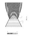
- FIGs. 3A- 3C are a representation of the flow field from a Computational Fluid Dynamics (CFD) solution for the 2D nozzle of the embodiment having a nozzle pressure ratio (NPR) of 5 (which is near the design condition for this nozzle) with varying injection flow described in greater detail subsequently.
- the Mach profile of the flow is shown in graded contours represented by the hatching in the flow field from Mach 0.5 to Mach 2.0.
- the fluidic injection takes place on surfaces 28 and 30 in the divergent section through slots 24 and 26.
- the flow separates aft of the throat 42 and the flow separation zone 44 persists to the exit aperture at the trailing edge 40 of the nozzle thus altering the effective exit area AE9.
- the nozzle exit area A9 results in a thrust coefficient of 0.933 as represented by point 52 on trace 54 and shown in FIG. 3A .
- a 2.6% injected flow (total injection from summing both injectors) through slots 24 and 26 results in a reduction in exit area providing a thrust coefficient of 0.957 as represented by point 56 and shown in FIG. 3B .
- Increasing the injected flow to 7.6% results in area AE9 change for a thrust coefficient of 0.965 as represented by point 58 and shown in FIG. 3C .
- the optimum amount of injection will depend on nozzle configuration, and the trend in thrust coefficient with injection flow is nonlinear. Injected flow in the range of 0 - 10% is anticipated for AE9 control through a desired performance range.
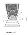
- FIG. 5 While examples previously provided herein are for 2D nozzles, three dimensional (3D) nozzles employing the apparatus and method may be embodied as shown in FIG. 5 .
- the convergent inlet portion 61 and divergent outlet portion 62 of nozzle 64 have corresponding geometric relationships to the 2D embodiments described with a total angle of less than 150° created by convergence angle of the inlet portion is greater than 18° and divergence angle 22 of the outlet portion greater than 12°.
- Multiple injection inlets 66 with associated feed conduits 68 are provided around the circumference of the diverging outlet portion of the nozzle. Eight inlets at 45° spacing are shown as examples. However, four inlets at 90° spacing or a greater number of inlets for refined control of wall separation by the jet may be employed.
- Multiple sets of injection inlets may be spaced along the length of the diverging outlet portion to accommodate multiple design operating conditions of the jet.
- a nozzle with convergent inlet and divergent outlet is provided in step 802 with preliminary determination of a desired total angle and convergence and divergence angles to achieve desired flow performance in step 800.
- Disturbance generators such as inlet flow slots, vibrating membranes or sonic impulse generators are located substantially symmetrically oppositely at a predetermined length along the divergent outlet portion of the nozzle in step 804 and the magnitude of the disturbance created by the generators is controlled to create a non-shock induced separation of the flow from the wall of the divergent outlet portion to create a separation zone extending substantially from the nozzle throat to the nozzle trailing edge of a magnitude to create a reduction in effective area of the jet flow at the nozzle exit in step 806.
- a feedback control loop would then be implemented to monitor the current exit flow area and the desired effective exit flow area. The feedback controller would increase/decrease injection to increase/decrease the nozzle effective exit flow area, respectively.
- An alternate embodiment of the present disclosure can be presented as an effective exit area control system for a nozzle comprising a convergent - divergent nozzle having a total angle no greater than 150 degrees, where a divergent portion of the nozzle has a wall having a predetermined angle of at least 12° from a streamwise nozzle axis, and it has a first injection flow slot on the divergent portion of the nozzle and a second injection flow slot on the divergent portion of the nozzle substantially opposite the first slot with respect to the axis, which each are controlled between 0% and 4% of total flow to induce flow separation from the wall. Furthermore said predetermined angle of the divergent portion wall induces flow separation to extend upstream from the first and second injection flow slots substantially to a throat of the nozzle pressurizing the divergent portion wall, thus creating a reduction in flow area through an exit of the nozzle.
- This embodiment's first and second injection flow slots are located between 25% and 75% and preferably at least 50% of a divergence length from the throat of the nozzle to a trailing edge of the nozzle.
Landscapes
- Engineering & Computer Science (AREA)
- Chemical & Material Sciences (AREA)
- Combustion & Propulsion (AREA)
- Mechanical Engineering (AREA)
- General Engineering & Computer Science (AREA)
- Nozzles (AREA)
- Jet Pumps And Other Pumps (AREA)
- Supercharger (AREA)
- Control Of Turbines (AREA)
- Aerodynamic Tests, Hydrodynamic Tests, Wind Tunnels, And Water Tanks (AREA)
Abstract
Description
- Exhaust nozzle exit area (A9) control for jet engines enhances engine and aircraft performance. With additional requirements for increased maneuverability and performance of modem jet aircraft as well as survivability requirements, fixed geometry nozzle systems which provide for exit area control including vectored thrust systems have become important in achieving overall performance goals. Exit area control allows tailoring of engine performance for thrust optimization. Mechanical systems often use deflecting surfaces to physically alter nozzle shape and area. Mechanical control of the throat area has been attempted before (see
US Patent 2,846,843 to Clark et al , entitled "Variable area convergent-divergent exhaust nozzle and control therefor") which does control the expansion ratio, but with a resulting change in the nozzle flow rate. - Fluidic systems have been employed but typically affect nozzle throat area or result in the generation of shocks in the divergent section which may be undesirable. Fluidic throat area control has been performed by as disclosed in
US Patent 5,996,936 to Mueller entitled "Fluidic throat exhaust nozzle", and suffers the same problem of nozzle flow rate variation with a change in expansion ratio. It has been attempted to control A9 with layers of combustible material which bum off during flight to give variable A9. SeeUS Patent Application serial number 09/942,238 to Hawkins and Murdock entitled "Combustible outgassing material lined altitude compensating rocket nozzle". However, it is not always desirable to have combustion occurring on the walls of a nozzle. Nor do combustibles allow cyclic changes of area control during a flight mission as the combustibles can only be used once. - A combined system as disclosed in
US Patent 3,010,280 to Hausmann et al entitled "Variable-expansion nozzle" employs blowing combustible mixtures into the divergent section to occupy flow area, thus reducing the overall nozzle exit area. Again, it is not always permissible to use combustibles near the walls of a nozzle due to material limitations. - Mechanical systems are heavy due to the requirements for large control surfaces and actuators. Large amounts of injected flow in fluidic systems are not preferable due to the performance impact on the engine to supply the large amounts of secondary flow for injection (flow that could otherwise be used to produce thrust). It is therefore desirable to avoid the weight penalties of mechanical nozzle exit area adjustment systems by providing effective exit area control. It is also desirable to provide effective exit area control which does not impact the nozzle throat area, thus easily maintaining the engine mass flow. Additionally, it is desirable to provide effective exit area control which is simple to implement and minimizes thrust losses.
- Embodiments of the disclosure relate generally to the field of area control of jet engine nozzle exhaust and more particularly to embodiments for inducing flow separation in the divergent section of an exhaust nozzle to symmetrically alter the effective divergence angle of the nozzle walls to alter effective exit area.
- The disclosed embodiments provide a nozzle with a divergent portion having a divergent wall at a predetermined angle of at least 12° from the streamwise nozzle axis direction. Disturbance generators are located substantially symmetrically opposite on the divergent wall to induce flow separation where the predetermined wall angle is sufficient for the induced flow separation to extend upstream from disturbance generator substantially to the throat of the nozzle. This pressurizes the divergent walls and reduces the effective area of the exhaust flow at the nozzle exit. In certain example embodiments the convergent - divergent nozzle has a total angle no greater than 150 degrees.
- For one embodiment the disturbance generator is an injection flow slot which may be located at least 50% of a divergence length from the throat of the nozzle to a trailing edge of the nozzle for certain engine and aerodynamic conditions or between 25% and 75% of a divergence length for alternative conditions. If the nozzle has sufficient structural depth, the injection may be performed at or near 100% of the divergence length. Injection flow through the injection slot is controlled between 0% and 4% of total flow for effective area control of the jet flow in the nozzle.
- In certain example embodiments the convergent-divergent nozzle is a rectangular or two-dimensional (2D) nozzle having a first injection flow slot on a lower wall of the nozzle and a symmetrical injection flow slot on an upper wall of the nozzle.
- In yet other embodiments the convergent-divergent nozzle is a three-dimensional (3D) nozzle having multiple injection flow slots arranged circumferentially around the divergent portion of the nozzle.
- In operation the embodiments create a method for exit area reduction by providing a convergent-divergent nozzle with a total angle of less than 150° and a divergence angle of at least 10° (considering some nozzle operating conditions permit the separation effect with as little as 10° of divergence), but preferably 12° or greater with symmetrical disturbance generators located at predetermined locations on opposing surfaces of a divergent portion of the nozzle. Magnitude of the disturbance created by the disturbance generators is controlled to create non-shock induced flow separation from a wall of the divergent portion. The predetermined location of the disturbance generator is defined to create a flow separation zone extending substantially from the nozzle throat to the nozzle trailing edge and the magnitude of the disturbance is controlled to create the flow separation zone with a magnitude to induce a desired reduction in effective exit area (AE9).
- The features, functions, and advantages that have been discussed can be achieved independently in various embodiments of the present invention or may be combined in yet other embodiments further details of which can be seen with reference to the following description and drawings.
-
-
FIG. 1 is side cross section view of an example embodiment with a 2D Nozzle; -
FIG. 2 is a side view diagram of angular relationships of convergent and divergent portions of the nozzle ofFIG. 1 ; -
FIGs. 3A - 3C are side views of representations of the flow field from a Computational Fluid Dynamics (CFD) solution for the 2D nozzle with no secondary flow, 2.6% secondary flow and 7.6% secondary flow; -
FIG. 4 is a graph of thrust coefficient created by injected flow in the 2D nozzle represented inFIGs. 3A- 3C ; -
FIG. 5 is a partial section isometric view of an example 3D nozzle embodiment; and, -
FIG. 6 is a flow chart depicting operation of the example nozzle for exit area control. - The embodiments described herein demonstrate effective exit area control employing a nozzle which has a convergent and divergent cross section. The divergent portion incorporates walls at an angle which is steeper than normally used in conventional nozzle designs. The steeper wall is then exploited to efficiently generate flow separation when a disturbance is introduced on the wall. Inducing flow separation in the divergent section of the nozzle fluidically changes the divergence angle of the flow from the wall in a two-dimensional (2D) nozzle or comparable structure in a three-dimensional (3D) nozzle. This results in a reduction in area of the exhaust flow as the effective shape of the divergent jet in the nozzle is separated from the wall. The disturbance which causes separation can be a fluidic jet, pulsed jet, or synthetic jet such as a vibrating membrane or sonic impulse with no net mass flux or other method to produce a disturbance to cause separation of the jet flow from the wall. The wall angle is such that the separation travels upstream from the disturbance (jet) to just aft of the throat. This pressurizes the entire wall, giving a net flow separation from the wall with a commensurate reduction in effective area of the exhaust flow at the exit of the nozzle. No shock is generated in the divergent section, the sonic line remains undisturbed and the throat area remains constant.
- Referring to the drawings,
FIG. 1 shows an embodiment having a side cross section of anozzle 10 with aconvergent inlet portion 12 and adivergent outlet portion 14. As represented inFIG. 2 , thetotal angle 16 between the convergent inlet portion and divergent outlet portion is less than or equal to 150°. With respect to a streamwise nozzle axis represented byarrow 18, theconvergence angle 20 of the inlet portion is greater than 18° and thedivergence angle 22 of the outlet portion is greater than 12°. The exact angles will be chosen by the designer taking into account the maximum area change desired as well as the desired expansion ratio and mass flow rates of the nozzle. Greater divergent angles will generally lead to greater divergence of the jet from the nozzle walls and greater reduction in AE9. In most embodiments, the convergent angle will be steeper than the divergent angle. Divergent angles substantially less than 12 degrees will typically result in shock waves when injection is performed and are not appropriate for the current embodiments. The exact angle of shock onset is dependant upon many factors such as expansion ratio and pressure, and the values employed in the embodiments disclosed herein are typical. - Returning to
FIG. 1 , flow disturbance in thedivergent outlet portion 14 is created in the embodiment shown using fluidic jets (represented by arrows 23) introduced throughflow slots upper nozzle surfaces Slot 26 is substantially symmetrically oppositeslot 24 with respect to the streamwise nozzle axis for symmetrical divergence of flow from the walls. Injection flow is provided by engine bleed or other diverted flow from anengine 32 throughducts midpoint 38 and trailingedge 40 of the divergent outlet portion. Injection locations further upstream may be beneficial to some applications and a nominal range of 25% to 75% of divergence length is anticipated for optimum operation. However, where structural depth to accommodate necessary plumbing is present in the nozzle, injection at 100% of the divergence length may be employed. - For an example of demonstration of operation of the disclosed embodiment,
FIGs. 3A- 3C are a representation of the flow field from a Computational Fluid Dynamics (CFD) solution for the 2D nozzle of the embodiment having a nozzle pressure ratio (NPR) of 5 (which is near the design condition for this nozzle) with varying injection flow described in greater detail subsequently. The Mach profile of the flow is shown in graded contours represented by the hatching in the flow field from Mach 0.5 to Mach 2.0. The fluidic injection takes place onsurfaces slots throat 42 and theflow separation zone 44 persists to the exit aperture at the trailingedge 40 of the nozzle thus altering the effective exit area AE9. No shock is formed from including the divergent wall injector since the separation begins just aft of the throat where the Mach number is unity. This concept effectively alters the divergence angle of the nozzle. Increasing injection flow results in an increasing change in effective exit area progressing fromFIG. 3A with a lower injection flow toFIG. 3C with highest injection flow. - Referring to
FIG. 4 in conjunction withFIGs. 3A - 3C , with injected flow described as a percent of total flow through the nozzle (% injected flow), with no injected flow, the nozzle exit area A9 results in a thrust coefficient of 0.933 as represented bypoint 52 ontrace 54 and shown inFIG. 3A . A 2.6% injected flow (total injection from summing both injectors) throughslots point 56 and shown inFIG. 3B . Increasing the injected flow to 7.6% results in area AE9 change for a thrust coefficient of 0.965 as represented bypoint 58 and shown inFIG. 3C . The optimum amount of injection will depend on nozzle configuration, and the trend in thrust coefficient with injection flow is nonlinear. Injected flow in the range of 0 - 10% is anticipated for AE9 control through a desired performance range. - While examples previously provided herein are for 2D nozzles, three dimensional (3D) nozzles employing the apparatus and method may be embodied as shown in
FIG. 5 . Theconvergent inlet portion 61 anddivergent outlet portion 62 of nozzle 64 have corresponding geometric relationships to the 2D embodiments described with a total angle of less than 150° created by convergence angle of the inlet portion is greater than 18° anddivergence angle 22 of the outlet portion greater than 12°.Multiple injection inlets 66 with associatedfeed conduits 68 are provided around the circumference of the diverging outlet portion of the nozzle. Eight inlets at 45° spacing are shown as examples. However, four inlets at 90° spacing or a greater number of inlets for refined control of wall separation by the jet may be employed. Multiple sets of injection inlets may be spaced along the length of the diverging outlet portion to accommodate multiple design operating conditions of the jet. - Operation of the embodiments disclosed herein is summarized in
FIG. 6 . A nozzle with convergent inlet and divergent outlet is provided in step 802 with preliminary determination of a desired total angle and convergence and divergence angles to achieve desired flow performance in step 800. Disturbance generators such as inlet flow slots, vibrating membranes or sonic impulse generators are located substantially symmetrically oppositely at a predetermined length along the divergent outlet portion of the nozzle in step 804 and the magnitude of the disturbance created by the generators is controlled to create a non-shock induced separation of the flow from the wall of the divergent outlet portion to create a separation zone extending substantially from the nozzle throat to the nozzle trailing edge of a magnitude to create a reduction in effective area of the jet flow at the nozzle exit in step 806. A feedback control loop would then be implemented to monitor the current exit flow area and the desired effective exit flow area. The feedback controller would increase/decrease injection to increase/decrease the nozzle effective exit flow area, respectively. - An alternate embodiment of the present disclosure can be presented as an effective exit area control system for a nozzle comprising a convergent - divergent nozzle having a total angle no greater than 150 degrees, where a divergent portion of the nozzle has a wall having a predetermined angle of at least 12° from a streamwise nozzle axis, and it has a first injection flow slot on the divergent portion of the nozzle and a second injection flow slot on the divergent portion of the nozzle substantially opposite the first slot with respect to the axis, which each are controlled between 0% and 4% of total flow to induce flow separation from the wall. Furthermore said predetermined angle of the divergent portion wall induces flow separation to extend upstream from the first and second injection flow slots substantially to a throat of the nozzle pressurizing the divergent portion wall, thus creating a reduction in flow area through an exit of the nozzle.
- This embodiment's first and second injection flow slots are located between 25% and 75% and preferably at least 50% of a divergence length from the throat of the nozzle to a trailing edge of the nozzle.
- Having now described various embodiments of the invention in detail as required by the patent statutes, those skilled in the art will recognize modifications and substitutions to the specific embodiments disclosed herein. Such modifications are within the scope and intent of the present invention as defined in the following claims.
Claims (10)
- A method for nozzle exit area control comprising:providing a convergent-divergent nozzle with a divergence angle of at least 12°;locating a pair of disturbance generator at predetermined locations substantially symmetrically opposite on a divergent portion of the nozzle; and,controlling a magnitude of a disturbance created by the disturbance generators to create non-shock induced flow separation from the divergent portion.
- The method of claim 1 wherein said predetermined locations of the disturbance generators are defined to create a flow separation zone extending substantially from a nozzle throat to a nozzle trailing edge inducing a desired nozzle exit area reduction.
- The method of claim 1 wherein the step of locating a pair of disturbance generators comprises providing injection flow slots on opposing walls of the divergent portion,
locating the flow injection slots between 25% and 75% and preferably at least 50% of a divergence length from a throat of the nozzle to a trailing edge of the nozzle, and
injecting a flow of between 0% and 10% of total flow through the slots. - The method of claim 1 wherein the step of locating disturbance generators comprises locating vibrating membranes on opposing walls of the divergent portion.
- The method of claim 1 wherein the step of locating disturbance generators comprises locating sonic impulse generators on opposing walls of the divergent portion.
- A nozzle effective exit area control system comprising:a convergent - divergent nozzle having a divergent portion wall at a predetermined angle of at least 12° from a streamwise nozzle axis; and,at least two disturbance generators located in substantially symmetric opposition on the divergent wall to induce flow separation from the divergent wall;said predetermined divergent wall angle inducing flow separation to extend upstream from the at least two disturbance generators substantially to a throat of the nozzle pressurizing the divergent portion wall and creating a reduction in flow area through an exit of the nozzle.
- The nozzle effective exit area control system of claim 6 wherein a convergent portion of the nozzle has a wall at a predetermined angle of at least 18°.
- The nozzle effective exit area control system of claim 6 wherein the disturbance generators are an injection flow slot,
the injection flow slots are located between 25% and 75% and preferably at least 50% of a divergence length from the throat of the nozzle to the exit of the nozzle, and
the injection flow through the injection slot is controlled between 0% and 10% of total flow. - The nozzle effective exit area control system of claim 8 wherein the convergent-divergent nozzle is a 2D nozzle and said at least two disturbance generators comprise a first injection flow slot on a lower divergent wall of the nozzle and a second injection flow slot on an upper divergent wall of the nozzle.
- The nozzle effective exit area control system of claim 8 wherein the convergent-divergent nozzle is a 3D nozzle and said at least two disturbance generators comprise a plurality of injection flow slots arranged circumferentially around the divergent portion of the nozzle.
Applications Claiming Priority (1)
| Application Number | Priority Date | Filing Date | Title |
|---|---|---|---|
| US12/968,106 US20120145808A1 (en) | 2010-12-14 | 2010-12-14 | Method and apparatus for variable exhaust nozzle exit area |
Publications (3)
| Publication Number | Publication Date |
|---|---|
| EP2466100A2 true EP2466100A2 (en) | 2012-06-20 |
| EP2466100A3 EP2466100A3 (en) | 2017-07-19 |
| EP2466100B1 EP2466100B1 (en) | 2019-09-11 |
Family
ID=45218544
Family Applications (1)
| Application Number | Title | Priority Date | Filing Date |
|---|---|---|---|
| EP11193592.0A Active EP2466100B1 (en) | 2010-12-14 | 2011-12-14 | Method and apparatus for variable exhaust nozzle exit area |
Country Status (5)
| Country | Link |
|---|---|
| US (1) | US20120145808A1 (en) |
| EP (1) | EP2466100B1 (en) |
| JP (1) | JP2012127349A (en) |
| CN (1) | CN102536512A (en) |
| CA (1) | CA2754855C (en) |
Cited By (1)
| Publication number | Priority date | Publication date | Assignee | Title |
|---|---|---|---|---|
| WO2019202269A1 (en) * | 2018-04-18 | 2019-10-24 | Centre National De La Recherche Scientifique | System for controlling speed transition and thrust vectorisation in a multiple-shaped nozzle by secondary injection |
Families Citing this family (20)
| Publication number | Priority date | Publication date | Assignee | Title |
|---|---|---|---|---|
| NL2007124C2 (en) * | 2011-07-15 | 2013-02-12 | Cor Leep | Economical jet propulsion principle. |
| US9297334B2 (en) * | 2012-05-25 | 2016-03-29 | King Abdulaziz City For Science And Technology | Exhaust nozzle of a gas turbine engine |
| CN102760193B (en) * | 2012-07-26 | 2014-09-17 | 中国航空工业集团公司沈阳发动机设计研究所 | Method for adjusting and designing outlet area of engine jet pipe based on installation performance |
| CN103291495B (en) * | 2013-05-21 | 2016-04-06 | 南京航空航天大学 | Ultrasound velocity/hypersonic aircraft motor overexpansion jet pipe bypass type device |
| CN103437911B (en) * | 2013-09-04 | 2015-11-18 | 北京航空航天大学 | Band dividing plate fluid controls dual vector jet pipe and vectored thrust produces and controlling method |
| CN104712460B (en) * | 2015-01-14 | 2016-04-20 | 北京理工大学 | A kind of solid propellant rocket of thrust controllable |
| CN104791134B (en) * | 2015-05-08 | 2016-07-06 | 北京理工大学 | A kind of replaceable Secondary Flow hits the flow field visual device of nozzle mutually |
| US12000336B2 (en) * | 2016-08-26 | 2024-06-04 | Jetoptera, Inc. | Variable geometry thruster |
| CA3034776A1 (en) * | 2016-08-25 | 2018-03-01 | Jetoptera, Inc. | Variable geometry thruster |
| CN106762218A (en) * | 2017-01-05 | 2017-05-31 | 南京工业职业技术学院 | A kind of method and jet pipe for improving pulse detonation engine thrust coefficient |
| CN107618654B (en) * | 2017-08-03 | 2021-03-30 | 南京航空航天大学 | Aircraft attitude control system, control method thereof and control nozzle |
| CN108035824A (en) * | 2017-11-08 | 2018-05-15 | 江西洪都航空工业集团有限责任公司 | A kind of pulsed secondary jet thrust vector control system |
| CN108412635B (en) * | 2018-02-07 | 2020-06-12 | 大连交通大学 | Binary direct-injection oblique shock wave thrust vectoring nozzle |
| US10807703B2 (en) * | 2018-07-19 | 2020-10-20 | General Electric Company | Control system for an aircraft |
| CN112610362A (en) * | 2020-12-18 | 2021-04-06 | 贵州航天朝阳科技有限责任公司 | Engine thrust control method and variable thrust engine |
| CN113389654B (en) * | 2021-07-20 | 2024-06-11 | 中国航空发动机研究院 | Vector spray pipe based on self-excitation pulse oscillation jet flow |
| CN114932019B (en) * | 2022-07-25 | 2022-11-01 | 中国空气动力研究与发展中心低速空气动力研究所 | Method for controlling expansion angle of rectangular jet flow |
| CN115342004A (en) * | 2022-08-30 | 2022-11-15 | 西北工业大学 | S-shaped pneumatic thrust vectoring nozzle capable of realizing pitching thrust vectoring and method |
| CN115539244B (en) * | 2022-09-14 | 2025-07-18 | 西北工业大学 | S-bend collecting and expanding spray pipe with adjustable cover plate and method |
| CN119825569B (en) * | 2025-03-19 | 2025-05-16 | 中国空气动力研究与发展中心低速空气动力研究所 | Thrust vector control method based on secondary flow channel pressure ratio combination control strategy |
Citations (3)
| Publication number | Priority date | Publication date | Assignee | Title |
|---|---|---|---|---|
| US2846843A (en) | 1953-01-07 | 1958-08-12 | Curtiss Wright Corp | Variable area convergent-divergent exhaust nozzle and control therefor |
| US3010280A (en) | 1958-03-25 | 1961-11-28 | United Aircraft Corp | Variable-expansion nozzle |
| US5996936A (en) | 1997-09-29 | 1999-12-07 | General Electric Company | Fluidic throat exhaust nozzle |
Family Cites Families (22)
| Publication number | Priority date | Publication date | Assignee | Title |
|---|---|---|---|---|
| US2943821A (en) * | 1950-12-30 | 1960-07-05 | United Aircraft Corp | Directional control means for a supersonic vehicle |
| US3109284A (en) * | 1956-06-14 | 1963-11-05 | Power Jets Res & Dev Ltd | Discharge nozzles for propulsive jets |
| FR1254416A (en) * | 1959-10-16 | 1961-02-24 | Bertin & Cie | Diffuser for fluid and devices including application |
| US3144752A (en) * | 1961-10-02 | 1964-08-18 | United Aircraft Corp | Injection thrust vectoring |
| US3646762A (en) * | 1962-09-04 | 1972-03-07 | Moog Inc | Secondary injection thrust vector control |
| US3374954A (en) * | 1966-03-03 | 1968-03-26 | Thiokol Chemical Corp | Nozzle cooling and thrust vector control apparatus |
| US3759039A (en) * | 1968-11-22 | 1973-09-18 | Thiokol Chemical Corp | Thrust control and modulation system |
| US4686824A (en) * | 1982-03-25 | 1987-08-18 | United States Of America As Represented By The Secretary Of The Army | Gaseous secondary injection thrust vector control device |
| FR2618488B1 (en) * | 1987-07-20 | 1989-12-15 | Europ Propulsion | DIVERGENT WITH BREAKING GALBE FOR NOZZLE OF MOTOR-ROCKET |
| US5101624A (en) * | 1989-09-07 | 1992-04-07 | General Electric Company | Exhaust nozzle hinge |
| US5435127A (en) * | 1993-11-15 | 1995-07-25 | General Electric Company | Method and apparatus for boosting ram airflow to an ejection nozzle |
| US6112513A (en) * | 1997-08-05 | 2000-09-05 | Lockheed Martin Corporation | Method and apparatus of asymmetric injection at the subsonic portion of a nozzle flow |
| US6112512A (en) * | 1997-08-05 | 2000-09-05 | Lockheed Martin Corporation | Method and apparatus of pulsed injection for improved nozzle flow control |
| US6390418B1 (en) * | 1999-02-25 | 2002-05-21 | United Technologies Corporation | Tangentially directed acoustic jet controlling boundary layer |
| FR2791398B1 (en) * | 1999-03-25 | 2001-05-18 | Agence Spatiale Europeenne | FUSED ENGINE NOZZLE COMPRISING A JET SEPARATION CONTROL SYSTEM |
| US6336319B1 (en) * | 2000-05-26 | 2002-01-08 | General Electric Company | Fluidic nozzle control system |
| US6679048B1 (en) * | 2000-10-24 | 2004-01-20 | Lockheed Martin Corporation | Apparatus and method for controlling primary fluid flow using secondary fluid flow injection |
| US6783824B2 (en) * | 2001-01-25 | 2004-08-31 | Hyper-Therm High-Temperature Composites, Inc. | Actively-cooled fiber-reinforced ceramic matrix composite rocket propulsion thrust chamber and method of producing the same |
| US7815146B2 (en) * | 2001-08-29 | 2010-10-19 | The Aerospace Corporation | Combustible outgassing material lined altitude compensating rocket nozzle |
| FR2858833B1 (en) * | 2003-08-12 | 2006-01-06 | Snecma Moteurs | CONVERGENT TUYERE DIVERGENT TURBOREACTOR |
| US7509797B2 (en) * | 2005-04-29 | 2009-03-31 | General Electric Company | Thrust vectoring missile turbojet |
| US8371104B2 (en) * | 2008-10-10 | 2013-02-12 | Lockheed Martin Corporation | System and apparatus for vectoring nozzle exhaust plume from a nozzle |
-
2010
- 2010-12-14 US US12/968,106 patent/US20120145808A1/en not_active Abandoned
-
2011
- 2011-10-11 CA CA2754855A patent/CA2754855C/en active Active
- 2011-12-13 JP JP2011271964A patent/JP2012127349A/en active Pending
- 2011-12-14 EP EP11193592.0A patent/EP2466100B1/en active Active
- 2011-12-14 CN CN2011104303832A patent/CN102536512A/en active Pending
Patent Citations (3)
| Publication number | Priority date | Publication date | Assignee | Title |
|---|---|---|---|---|
| US2846843A (en) | 1953-01-07 | 1958-08-12 | Curtiss Wright Corp | Variable area convergent-divergent exhaust nozzle and control therefor |
| US3010280A (en) | 1958-03-25 | 1961-11-28 | United Aircraft Corp | Variable-expansion nozzle |
| US5996936A (en) | 1997-09-29 | 1999-12-07 | General Electric Company | Fluidic throat exhaust nozzle |
Cited By (3)
| Publication number | Priority date | Publication date | Assignee | Title |
|---|---|---|---|---|
| WO2019202269A1 (en) * | 2018-04-18 | 2019-10-24 | Centre National De La Recherche Scientifique | System for controlling speed transition and thrust vectorisation in a multiple-shaped nozzle by secondary injection |
| FR3080407A1 (en) * | 2018-04-18 | 2019-10-25 | Centre National De La Recherche Scientifique | REGULATORY TRANSITION CONTROL AND PUSH VECTORIZATION IN A MULTIPLE GALBE PIPE BY SECONDARY INJECTION |
| US11661910B2 (en) | 2018-04-18 | 2023-05-30 | Centre National De La Recherche Scientifique | System for controlling speed transition and thrust vectorisation in a multiple-shaped nozzle by secondary injection |
Also Published As
| Publication number | Publication date |
|---|---|
| CA2754855C (en) | 2014-10-07 |
| US20120145808A1 (en) | 2012-06-14 |
| EP2466100A3 (en) | 2017-07-19 |
| CN102536512A (en) | 2012-07-04 |
| EP2466100B1 (en) | 2019-09-11 |
| CA2754855A1 (en) | 2012-06-14 |
| JP2012127349A (en) | 2012-07-05 |
Similar Documents
| Publication | Publication Date | Title |
|---|---|---|
| EP2466100B1 (en) | Method and apparatus for variable exhaust nozzle exit area | |
| US9551296B2 (en) | Method and apparatus for nozzle thrust vectoring | |
| US7784284B2 (en) | Exhaust assembly forming a horizontal propulsion gas elbow in an aircraft | |
| US7966826B2 (en) | Systems and methods for reducing noise from jet engine exhaust | |
| US7681400B2 (en) | Exhaust assembly forming a horizontal propulsion gas elbow in an aircraft | |
| US8746613B2 (en) | Jet engine exhaust nozzle and associated system and method of use | |
| Das et al. | Fluidic thrust vector control of aerospace vehicles: State-of-the-art review and future prospects | |
| US10060389B2 (en) | Method and apparatus for variable exhaust nozzle exit area | |
| US7581400B2 (en) | Elbow-shaped propulsion gas exhaust assembly in an aircraft | |
| KR20170004844A (en) | Inlet flow restrictor | |
| US20240084764A1 (en) | Hypersonic vehicle and scramjet engine with variable fuel injection for operation over a large mach number range | |
| US4707981A (en) | Variable expansion ratio reaction engine | |
| JP6258101B2 (en) | Jet engine, flying object and operation method of jet engine | |
| JP2015197058A (en) | Jet engine, flying object and operation method of jet engine | |
| EP2865874A2 (en) | Methods and apparatus for passive thrust vectoring and plume deflection | |
| US3407603A (en) | Reaction propulsion engines | |
| US7631486B2 (en) | Thrust orienting nozzle | |
| Goodwin et al. | Performance analysis of a hypersonic scramjet engine with a morphable waverider inlet | |
| EP2659118B1 (en) | Flight vehicle, propulsion system and thrust vectoring system | |
| Tan et al. | A new concept and preliminary study of variable hypersonic inlet with fixed geometry based on shockwave control | |
| Yungster et al. | Numerical evaluation of an ejector-enhanced resonant pulse combustor with a poppet inlet valve and a converging exhaust nozzle | |
| EP1585896A1 (en) | Apparatus and method for controlling primary fluid flow using secondary fluid flow injection | |
| JP2014122607A (en) | Scramjet engine and combustion control method | |
| KR20160021331A (en) | A Gas flow adjuster | |
| WO2015092787A2 (en) | Jet propulsion engine |
Legal Events
| Date | Code | Title | Description |
|---|---|---|---|
| PUAI | Public reference made under article 153(3) epc to a published international application that has entered the european phase |
Free format text: ORIGINAL CODE: 0009012 |
|
| 17P | Request for examination filed |
Effective date: 20111214 |
|
| AK | Designated contracting states |
Kind code of ref document: A2 Designated state(s): AL AT BE BG CH CY CZ DE DK EE ES FI FR GB GR HR HU IE IS IT LI LT LU LV MC MK MT NL NO PL PT RO RS SE SI SK SM TR |
|
| AX | Request for extension of the european patent |
Extension state: BA ME |
|
| PUAL | Search report despatched |
Free format text: ORIGINAL CODE: 0009013 |
|
| AK | Designated contracting states |
Kind code of ref document: A3 Designated state(s): AL AT BE BG CH CY CZ DE DK EE ES FI FR GB GR HR HU IE IS IT LI LT LU LV MC MK MT NL NO PL PT RO RS SE SI SK SM TR |
|
| AX | Request for extension of the european patent |
Extension state: BA ME |
|
| RIC1 | Information provided on ipc code assigned before grant |
Ipc: F02K 1/30 20060101AFI20170614BHEP Ipc: F02K 9/82 20060101ALI20170614BHEP |
|
| STAA | Information on the status of an ep patent application or granted ep patent |
Free format text: STATUS: EXAMINATION IS IN PROGRESS |
|
| 17Q | First examination report despatched |
Effective date: 20180713 |
|
| GRAP | Despatch of communication of intention to grant a patent |
Free format text: ORIGINAL CODE: EPIDOSNIGR1 |
|
| STAA | Information on the status of an ep patent application or granted ep patent |
Free format text: STATUS: GRANT OF PATENT IS INTENDED |
|
| INTG | Intention to grant announced |
Effective date: 20190226 |
|
| GRAJ | Information related to disapproval of communication of intention to grant by the applicant or resumption of examination proceedings by the epo deleted |
Free format text: ORIGINAL CODE: EPIDOSDIGR1 |
|
| STAA | Information on the status of an ep patent application or granted ep patent |
Free format text: STATUS: EXAMINATION IS IN PROGRESS |
|
| INTC | Intention to grant announced (deleted) | ||
| GRAR | Information related to intention to grant a patent recorded |
Free format text: ORIGINAL CODE: EPIDOSNIGR71 |
|
| GRAS | Grant fee paid |
Free format text: ORIGINAL CODE: EPIDOSNIGR3 |
|
| STAA | Information on the status of an ep patent application or granted ep patent |
Free format text: STATUS: GRANT OF PATENT IS INTENDED |
|
| GRAA | (expected) grant |
Free format text: ORIGINAL CODE: 0009210 |
|
| STAA | Information on the status of an ep patent application or granted ep patent |
Free format text: STATUS: THE PATENT HAS BEEN GRANTED |
|
| AK | Designated contracting states |
Kind code of ref document: B1 Designated state(s): AL AT BE BG CH CY CZ DE DK EE ES FI FR GB GR HR HU IE IS IT LI LT LU LV MC MK MT NL NO PL PT RO RS SE SI SK SM TR |
|
| INTG | Intention to grant announced |
Effective date: 20190805 |
|
| REG | Reference to a national code |
Ref country code: GB Ref legal event code: FG4D |
|
| RIN1 | Information on inventor provided before grant (corrected) |
Inventor name: DORGAN, ANDREW J. Inventor name: WINKLER, CHAD M. Inventor name: WERNER, ERIC L. |
|
| REG | Reference to a national code |
Ref country code: CH Ref legal event code: EP |
|
| REG | Reference to a national code |
Ref country code: AT Ref legal event code: REF Ref document number: 1178766 Country of ref document: AT Kind code of ref document: T Effective date: 20190915 |
|
| REG | Reference to a national code |
Ref country code: DE Ref legal event code: R096 Ref document number: 602011061954 Country of ref document: DE |
|
| REG | Reference to a national code |
Ref country code: IE Ref legal event code: FG4D |
|
| REG | Reference to a national code |
Ref country code: NL Ref legal event code: MP Effective date: 20190911 |
|
| REG | Reference to a national code |
Ref country code: LT Ref legal event code: MG4D |
|
| PG25 | Lapsed in a contracting state [announced via postgrant information from national office to epo] |
Ref country code: SE Free format text: LAPSE BECAUSE OF FAILURE TO SUBMIT A TRANSLATION OF THE DESCRIPTION OR TO PAY THE FEE WITHIN THE PRESCRIBED TIME-LIMIT Effective date: 20190911 Ref country code: BG Free format text: LAPSE BECAUSE OF FAILURE TO SUBMIT A TRANSLATION OF THE DESCRIPTION OR TO PAY THE FEE WITHIN THE PRESCRIBED TIME-LIMIT Effective date: 20191211 Ref country code: NO Free format text: LAPSE BECAUSE OF FAILURE TO SUBMIT A TRANSLATION OF THE DESCRIPTION OR TO PAY THE FEE WITHIN THE PRESCRIBED TIME-LIMIT Effective date: 20191211 Ref country code: LT Free format text: LAPSE BECAUSE OF FAILURE TO SUBMIT A TRANSLATION OF THE DESCRIPTION OR TO PAY THE FEE WITHIN THE PRESCRIBED TIME-LIMIT Effective date: 20190911 Ref country code: FI Free format text: LAPSE BECAUSE OF FAILURE TO SUBMIT A TRANSLATION OF THE DESCRIPTION OR TO PAY THE FEE WITHIN THE PRESCRIBED TIME-LIMIT Effective date: 20190911 Ref country code: HR Free format text: LAPSE BECAUSE OF FAILURE TO SUBMIT A TRANSLATION OF THE DESCRIPTION OR TO PAY THE FEE WITHIN THE PRESCRIBED TIME-LIMIT Effective date: 20190911 |
|
| PG25 | Lapsed in a contracting state [announced via postgrant information from national office to epo] |
Ref country code: LV Free format text: LAPSE BECAUSE OF FAILURE TO SUBMIT A TRANSLATION OF THE DESCRIPTION OR TO PAY THE FEE WITHIN THE PRESCRIBED TIME-LIMIT Effective date: 20190911 Ref country code: AL Free format text: LAPSE BECAUSE OF FAILURE TO SUBMIT A TRANSLATION OF THE DESCRIPTION OR TO PAY THE FEE WITHIN THE PRESCRIBED TIME-LIMIT Effective date: 20190911 Ref country code: RS Free format text: LAPSE BECAUSE OF FAILURE TO SUBMIT A TRANSLATION OF THE DESCRIPTION OR TO PAY THE FEE WITHIN THE PRESCRIBED TIME-LIMIT Effective date: 20190911 Ref country code: GR Free format text: LAPSE BECAUSE OF FAILURE TO SUBMIT A TRANSLATION OF THE DESCRIPTION OR TO PAY THE FEE WITHIN THE PRESCRIBED TIME-LIMIT Effective date: 20191212 Ref country code: ES Free format text: LAPSE BECAUSE OF FAILURE TO SUBMIT A TRANSLATION OF THE DESCRIPTION OR TO PAY THE FEE WITHIN THE PRESCRIBED TIME-LIMIT Effective date: 20190911 |
|
| REG | Reference to a national code |
Ref country code: AT Ref legal event code: MK05 Ref document number: 1178766 Country of ref document: AT Kind code of ref document: T Effective date: 20190911 |
|
| PG25 | Lapsed in a contracting state [announced via postgrant information from national office to epo] |
Ref country code: AT Free format text: LAPSE BECAUSE OF FAILURE TO SUBMIT A TRANSLATION OF THE DESCRIPTION OR TO PAY THE FEE WITHIN THE PRESCRIBED TIME-LIMIT Effective date: 20190911 Ref country code: IT Free format text: LAPSE BECAUSE OF FAILURE TO SUBMIT A TRANSLATION OF THE DESCRIPTION OR TO PAY THE FEE WITHIN THE PRESCRIBED TIME-LIMIT Effective date: 20190911 Ref country code: EE Free format text: LAPSE BECAUSE OF FAILURE TO SUBMIT A TRANSLATION OF THE DESCRIPTION OR TO PAY THE FEE WITHIN THE PRESCRIBED TIME-LIMIT Effective date: 20190911 Ref country code: PL Free format text: LAPSE BECAUSE OF FAILURE TO SUBMIT A TRANSLATION OF THE DESCRIPTION OR TO PAY THE FEE WITHIN THE PRESCRIBED TIME-LIMIT Effective date: 20190911 Ref country code: PT Free format text: LAPSE BECAUSE OF FAILURE TO SUBMIT A TRANSLATION OF THE DESCRIPTION OR TO PAY THE FEE WITHIN THE PRESCRIBED TIME-LIMIT Effective date: 20200113 Ref country code: RO Free format text: LAPSE BECAUSE OF FAILURE TO SUBMIT A TRANSLATION OF THE DESCRIPTION OR TO PAY THE FEE WITHIN THE PRESCRIBED TIME-LIMIT Effective date: 20190911 Ref country code: NL Free format text: LAPSE BECAUSE OF FAILURE TO SUBMIT A TRANSLATION OF THE DESCRIPTION OR TO PAY THE FEE WITHIN THE PRESCRIBED TIME-LIMIT Effective date: 20190911 |
|
| PG25 | Lapsed in a contracting state [announced via postgrant information from national office to epo] |
Ref country code: CZ Free format text: LAPSE BECAUSE OF FAILURE TO SUBMIT A TRANSLATION OF THE DESCRIPTION OR TO PAY THE FEE WITHIN THE PRESCRIBED TIME-LIMIT Effective date: 20190911 Ref country code: IS Free format text: LAPSE BECAUSE OF FAILURE TO SUBMIT A TRANSLATION OF THE DESCRIPTION OR TO PAY THE FEE WITHIN THE PRESCRIBED TIME-LIMIT Effective date: 20200224 Ref country code: SK Free format text: LAPSE BECAUSE OF FAILURE TO SUBMIT A TRANSLATION OF THE DESCRIPTION OR TO PAY THE FEE WITHIN THE PRESCRIBED TIME-LIMIT Effective date: 20190911 Ref country code: SM Free format text: LAPSE BECAUSE OF FAILURE TO SUBMIT A TRANSLATION OF THE DESCRIPTION OR TO PAY THE FEE WITHIN THE PRESCRIBED TIME-LIMIT Effective date: 20190911 |
|
| REG | Reference to a national code |
Ref country code: DE Ref legal event code: R097 Ref document number: 602011061954 Country of ref document: DE |
|
| PLBE | No opposition filed within time limit |
Free format text: ORIGINAL CODE: 0009261 |
|
| STAA | Information on the status of an ep patent application or granted ep patent |
Free format text: STATUS: NO OPPOSITION FILED WITHIN TIME LIMIT |
|
| PG2D | Information on lapse in contracting state deleted |
Ref country code: IS |
|
| PG25 | Lapsed in a contracting state [announced via postgrant information from national office to epo] |
Ref country code: DK Free format text: LAPSE BECAUSE OF FAILURE TO SUBMIT A TRANSLATION OF THE DESCRIPTION OR TO PAY THE FEE WITHIN THE PRESCRIBED TIME-LIMIT Effective date: 20190911 Ref country code: IS Free format text: LAPSE BECAUSE OF FAILURE TO SUBMIT A TRANSLATION OF THE DESCRIPTION OR TO PAY THE FEE WITHIN THE PRESCRIBED TIME-LIMIT Effective date: 20200112 |
|
| REG | Reference to a national code |
Ref country code: CH Ref legal event code: PL |
|
| 26N | No opposition filed |
Effective date: 20200615 |
|
| REG | Reference to a national code |
Ref country code: BE Ref legal event code: MM Effective date: 20191231 |
|
| PG25 | Lapsed in a contracting state [announced via postgrant information from national office to epo] |
Ref country code: SI Free format text: LAPSE BECAUSE OF FAILURE TO SUBMIT A TRANSLATION OF THE DESCRIPTION OR TO PAY THE FEE WITHIN THE PRESCRIBED TIME-LIMIT Effective date: 20190911 Ref country code: MC Free format text: LAPSE BECAUSE OF FAILURE TO SUBMIT A TRANSLATION OF THE DESCRIPTION OR TO PAY THE FEE WITHIN THE PRESCRIBED TIME-LIMIT Effective date: 20190911 |
|
| PG25 | Lapsed in a contracting state [announced via postgrant information from national office to epo] |
Ref country code: IE Free format text: LAPSE BECAUSE OF NON-PAYMENT OF DUE FEES Effective date: 20191214 Ref country code: LU Free format text: LAPSE BECAUSE OF NON-PAYMENT OF DUE FEES Effective date: 20191214 |
|
| PG25 | Lapsed in a contracting state [announced via postgrant information from national office to epo] |
Ref country code: BE Free format text: LAPSE BECAUSE OF NON-PAYMENT OF DUE FEES Effective date: 20191231 Ref country code: LI Free format text: LAPSE BECAUSE OF NON-PAYMENT OF DUE FEES Effective date: 20191231 Ref country code: CH Free format text: LAPSE BECAUSE OF NON-PAYMENT OF DUE FEES Effective date: 20191231 |
|
| PG25 | Lapsed in a contracting state [announced via postgrant information from national office to epo] |
Ref country code: CY Free format text: LAPSE BECAUSE OF FAILURE TO SUBMIT A TRANSLATION OF THE DESCRIPTION OR TO PAY THE FEE WITHIN THE PRESCRIBED TIME-LIMIT Effective date: 20190911 |
|
| PG25 | Lapsed in a contracting state [announced via postgrant information from national office to epo] |
Ref country code: HU Free format text: LAPSE BECAUSE OF FAILURE TO SUBMIT A TRANSLATION OF THE DESCRIPTION OR TO PAY THE FEE WITHIN THE PRESCRIBED TIME-LIMIT; INVALID AB INITIO Effective date: 20111214 Ref country code: MT Free format text: LAPSE BECAUSE OF FAILURE TO SUBMIT A TRANSLATION OF THE DESCRIPTION OR TO PAY THE FEE WITHIN THE PRESCRIBED TIME-LIMIT Effective date: 20190911 |
|
| PG25 | Lapsed in a contracting state [announced via postgrant information from national office to epo] |
Ref country code: TR Free format text: LAPSE BECAUSE OF FAILURE TO SUBMIT A TRANSLATION OF THE DESCRIPTION OR TO PAY THE FEE WITHIN THE PRESCRIBED TIME-LIMIT Effective date: 20190911 |
|
| PG25 | Lapsed in a contracting state [announced via postgrant information from national office to epo] |
Ref country code: MK Free format text: LAPSE BECAUSE OF FAILURE TO SUBMIT A TRANSLATION OF THE DESCRIPTION OR TO PAY THE FEE WITHIN THE PRESCRIBED TIME-LIMIT Effective date: 20190911 |
|
| P01 | Opt-out of the competence of the unified patent court (upc) registered |
Effective date: 20230516 |
|
| PGFP | Annual fee paid to national office [announced via postgrant information from national office to epo] |
Ref country code: GB Payment date: 20251229 Year of fee payment: 15 |
|
| PGFP | Annual fee paid to national office [announced via postgrant information from national office to epo] |
Ref country code: FR Payment date: 20251226 Year of fee payment: 15 |
|
| PGFP | Annual fee paid to national office [announced via postgrant information from national office to epo] |
Ref country code: DE Payment date: 20251229 Year of fee payment: 15 |