EP2466077A1 - Steam turbine overspeed protection - Google Patents
Steam turbine overspeed protection Download PDFInfo
- Publication number
- EP2466077A1 EP2466077A1 EP10195773A EP10195773A EP2466077A1 EP 2466077 A1 EP2466077 A1 EP 2466077A1 EP 10195773 A EP10195773 A EP 10195773A EP 10195773 A EP10195773 A EP 10195773A EP 2466077 A1 EP2466077 A1 EP 2466077A1
- Authority
- EP
- European Patent Office
- Prior art keywords
- control
- steam turbine
- overspeed
- trigger event
- time
- Prior art date
- Legal status (The legal status is an assumption and is not a legal conclusion. Google has not performed a legal analysis and makes no representation as to the accuracy of the status listed.)
- Withdrawn
Links
Images

Classifications
-
- F—MECHANICAL ENGINEERING; LIGHTING; HEATING; WEAPONS; BLASTING
- F01—MACHINES OR ENGINES IN GENERAL; ENGINE PLANTS IN GENERAL; STEAM ENGINES
- F01D—NON-POSITIVE DISPLACEMENT MACHINES OR ENGINES, e.g. STEAM TURBINES
- F01D21/00—Shutting-down of machines or engines, e.g. in emergency; Regulating, controlling, or safety means not otherwise provided for
- F01D21/02—Shutting-down responsive to overspeed
-
- F—MECHANICAL ENGINEERING; LIGHTING; HEATING; WEAPONS; BLASTING
- F05—INDEXING SCHEMES RELATING TO ENGINES OR PUMPS IN VARIOUS SUBCLASSES OF CLASSES F01-F04
- F05D—INDEXING SCHEME FOR ASPECTS RELATING TO NON-POSITIVE-DISPLACEMENT MACHINES OR ENGINES, GAS-TURBINES OR JET-PROPULSION PLANTS
- F05D2220/00—Application
- F05D2220/30—Application in turbines
- F05D2220/31—Application in turbines in steam turbines
-
- F—MECHANICAL ENGINEERING; LIGHTING; HEATING; WEAPONS; BLASTING
- F05—INDEXING SCHEMES RELATING TO ENGINES OR PUMPS IN VARIOUS SUBCLASSES OF CLASSES F01-F04
- F05D—INDEXING SCHEME FOR ASPECTS RELATING TO NON-POSITIVE-DISPLACEMENT MACHINES OR ENGINES, GAS-TURBINES OR JET-PROPULSION PLANTS
- F05D2270/00—Control
- F05D2270/01—Purpose of the control system
- F05D2270/02—Purpose of the control system to control rotational speed (n)
- F05D2270/021—Purpose of the control system to control rotational speed (n) to prevent overspeed
Definitions
- the present disclosure relates generally to steam turbine overspeed protection and more specifically to the control of overspeed in the case of a steam turbine unloading event.
- steam turbines are equipped with trip systems to ensure that the steam turbine speed does not exceed a defined overspeed value. Overspeed may occur following steam turbine unloading events and result in a transient rotational speed spike caused by the delay in system dynamics and control system lag as the turbine's control system assumes new control positions.
- the event may be an undetectable load shedding event, such as a sudden drop in power demand, or else a detectable event, such as the opening of a power breaker.
- Power grid codes typically pre-define operating bands that limit operation above nominal speeds.
- the overspeed trip setpoint is thus determined by adding the expected overspeed resulting from a load shedding event to the peak overspeed within an operating band.
- the power plant is available to be brought on line as soon as possible. As it may take long to bring a plant on line after a trip is preferable to limit the number of trips.
- Machine damage may also occur below the maximum rotor designed overspeed if, for example, resonance build-up occurs within the blading. While damaging resonance build-up in the blading typically occurs only if a particular system specific overspeed is sustained and so does not occur during transient overspeed events such as unloading events, it is nonetheless preferable to minimise the exposure of blades to overspeed in order to reduce potential blade stressing.
- An objective of the invention is to overcome the problem of steam turbine overspeed exposure during upset conditions..
- the disclosure is based on the general idea of varying the trip setting based on the monitoring of an intermediate steam turbine control system parameters. If the intermediate control parameter has neither started nor completed its expected action within a predetermined time an alert is raised. The underlying presumption is that in such a case a control fault has occurred which means the control system will not be able to prevent the tripping of the steam turbine on overspeed.
- a further aspect therefore provides a steam turbine trip thus limiting the overspeed exposure of the steam turbine.
- An aspect therefore provides a steam turbine compromising an overspeed control system for responding to the deloading of the steam turbine.
- the control system comprises: a control system fault alert for identifying a fault in the control system; a trigger event that defines the point of deloading of the steam turbine; a control feature configured to achieve a control states in respond to the deloading; and a predetermined control time defined as the expected time interval between the trigger event and the point at which the control feature has achieved the control state.
- the control system fault alert is configured to initiate if, in response to the deloading of the steam turbine, the control states is not achieved with the control time.
- Another aspect provides a method of generating a steam turbine overspeed control system fault alert comprising providing a steam turbine with the overspeed control system wherein the control system has a trigger event that defines the point of deloading of the steam turbine.
- a control feature configured to achieve a control state in response to the trigger event within a control time, is provided to the control system. The method further includes initiating a fault alert if the control state is not achieved within the control time.
- an overspeed control system 16 for preventing or at least minimising overspeed OS of a steam turbine 10 in both normal and upset conditions is provided.
- a steam turbine 10 compromises an overspeed control system 16 for responding to the deloading of the steam turbine 10.
- the control system 16 has: a control system fault alert FA for identifying a fault in the control system 16; a trigger event TE used to identify of the steam turbine 10 is deloading; a control feature 12 configured to achieve a control state CS in response to the deloading; and a control time CT defined as the estimated time it takes between first initiation of the trigger event TE and the point in time at which the control feature 12 achieves the control states CS.
- a fault alert FA maybe provided.
- the fault alert FA maybe used simply as a fault indicator or alternatively as a means to initiate a steam turbine trip.
- a trigger event TE may be any indication that identifies that a steam turbine 10 unloading event has occurred.
- the trigger event TE may be a predefined overspeed OS or alternatively, when the steam turbine 10 is a component of a power plant, a signal that a breaker 18 of the power plant, as shown in Fig. 1 , is open.
- a control feature 12, as shown in Fig. 1 may be a steam control valve for controlling the amount of steam fed to the steam turbine 10 by means of changing the control states CS of the control valve.
- a control feature 12 may be an extraction control valve (not shown) for controlling steam extraction from the steam turbine 10.
- Examples of control states CS include predefined valve positions, such as partially open or closed, and valve position ranges, such as "less than 80% open”.
- control time CT is also directly related to a trigger event TE as it forms the basis for the measurement, in a further exemplary embodiment shown in Fig. 5 , overspeed OS is further used as an indication of the trigger event TE.
- a fault alert FA is configured to initiate if the steam turbine 10 achieves an overspeed OS if the control feature 12 has not achieved the control states CS.
- Each of these exemplary embodiments may comprise control features 12 that each comprise several control actions resulting in either as final control states CS or intermediate control states CS.
- a final control state CS is a state of the control feature 12 that has the longest control time CT of all the control states CS of that control feature 12.
- An example of a final control state CY is the closed state a valve control feature 12 that is normally open.
- an intermediate control state CS is a partially open valve position or alternative a range of partially open valve position above a certain value.
- control feature 12 is a steam control valve for controlling the amount of steam fed to a steam turbine 10 and the control state CS is the closing of the control valve below an estimated value that is estimated based on nominal full load steam turbine 10 operation.
- control feature 12 is also a steam control valve for controlling the steam flow to a steam turbine 10 but the control action is the full closure of the steam control valve.
- control feature 12 includes a control measurement device for determining the control states CS of the control feature 12.
- a control measurement device for determining the control states CS of the control feature 12.
- An example is a proximity switch located on an exemplary control valve.
- control system 16 includes a plurality of control features 12 wherein the by means of a voting system, the status of the control system 16 is determined. For example, in an embodiment with two control features 12, a fault alert FA may be initiated if either one or both of the control features 12 does not achieve the expected control state CS. With further control features 12 other redundant voting systems maybe used, for example, one out of three, two out of three, three out of three etc.
- control state CS is determined by means of a measurement device. In another not shown exemplary embodiment the control state CS is determined by means of the command to the control feature 12.
Landscapes
- Engineering & Computer Science (AREA)
- Mechanical Engineering (AREA)
- General Engineering & Computer Science (AREA)
- Control Of Turbines (AREA)
Abstract
A steam turbine (10) comprises an overspeed control system (16) for responding to the deloading of the steam turbine (10). The steam turbine (10) has a control system (16) with: a control system fault alert (FA) for identifying a fault in the control system (16); a trigger event (TE) defining the point of deloading of the steam turbine (10); a control feature (12) configured to achieve a control state (CS) in response to the deloading; and a predetermined control time (CT) providing an expected time interval between the trigger event (TE) and the point in time at which the control feature (12) achieves the control state (CS). The control system fault alert (FA) is configured to initiate if, in response to the deloading of the steam turbine (10), the control state (CS) is not achieved within the control time (CT). In this way, an active alert is provided that may be used as a fault warning and/or steam turbine (10) trip.
Description
- The present disclosure relates generally to steam turbine overspeed protection and more specifically to the control of overspeed in the case of a steam turbine unloading event.
- Typically, steam turbines are equipped with trip systems to ensure that the steam turbine speed does not exceed a defined overspeed value. Overspeed may occur following steam turbine unloading events and result in a transient rotational speed spike caused by the delay in system dynamics and control system lag as the turbine's control system assumes new control positions. The event may be an undetectable load shedding event, such as a sudden drop in power demand, or else a detectable event, such as the opening of a power breaker.
- Power grid codes typically pre-define operating bands that limit operation above nominal speeds. The overspeed trip setpoint is thus determined by adding the expected overspeed resulting from a load shedding event to the peak overspeed within an operating band.
- Following an unloading event, it is generally preferable that the power plant is available to be brought on line as soon as possible. As it may take long to bring a plant on line after a trip is preferable to limit the number of trips.
- Machine damage may also occur below the maximum rotor designed overspeed if, for example, resonance build-up occurs within the blading. While damaging resonance build-up in the blading typically occurs only if a particular system specific overspeed is sustained and so does not occur during transient overspeed events such as unloading events, it is nonetheless preferable to minimise the exposure of blades to overspeed in order to reduce potential blade stressing.
- An objective of the invention is to overcome the problem of steam turbine overspeed exposure during upset conditions..
- The disclosure attempts to address this problem by means of the subject matters of the independent claims. Advantageous embodiments are given in the dependent claims.
- The disclosure is based on the general idea of varying the trip setting based on the monitoring of an intermediate steam turbine control system parameters. If the intermediate control parameter has neither started nor completed its expected action within a predetermined time an alert is raised. The underlying presumption is that in such a case a control fault has occurred which means the control system will not be able to prevent the tripping of the steam turbine on overspeed. A further aspect therefore provides a steam turbine trip thus limiting the overspeed exposure of the steam turbine.
- An aspect therefore provides a steam turbine compromising an overspeed control system for responding to the deloading of the steam turbine. The control system comprises: a control system fault alert for identifying a fault in the control system; a trigger event that defines the point of deloading of the steam turbine; a control feature configured to achieve a control states in respond to the deloading; and a predetermined control time defined as the expected time interval between the trigger event and the point at which the control feature has achieved the control state. In this arrangement the control system fault alert is configured to initiate if, in response to the deloading of the steam turbine, the control states is not achieved with the control time.
- Another aspect provides a method of generating a steam turbine overspeed control system fault alert comprising providing a steam turbine with the overspeed control system wherein the control system has a trigger event that defines the point of deloading of the steam turbine. A control feature, configured to achieve a control state in response to the trigger event within a control time, is provided to the control system. The method further includes initiating a fault alert if the control state is not achieved within the control time.
- Other aspects and advantages of the present disclosure will become apparent from the following description, taken in connection with the accompanying drawings, which by way of example illustrate exemplary embodiments of the present invention
- By way of example, an embodiment of the present disclosure is described more fully hereinafter with reference to the accompanying drawings, in which:
-
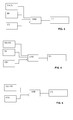
Figure 1 is a schematic of an exemplary steam plant ; -
Figure 2 is an exemplary correlation, for the steam plant ofFig. 1 of overspeed to control time; and -
Figure 3 -5 are various embodiments of control logic of the steam plant ofFig. 1 - Exemplary embodiments of the present disclosure are now described with references to the drawings, wherein like reference numerals are used to refer to like elements throughout. In the following description, for purposes of explanation, numerous specific details are set forth to provide a thorough understanding of the disclosure. However, the present disclosure may be practiced without these specific details, and is not limited to the exemplary embodiments disclosed herein.
- In an exemplary embodiment, applied to a
steam turbine 10 shown inFig. 1 , anoverspeed control system 16 for preventing or at least minimising overspeed OS of asteam turbine 10 in both normal and upset conditions is provided. - In an exemplary embodiment shown in
Fig. 1 , asteam turbine 10 compromises anoverspeed control system 16 for responding to the deloading of thesteam turbine 10. In order to control the overspeed OS and provide an alert of apotential control system 16 fault, thecontrol system 16, as shown inFig. 3 , has: a control system fault alert FA for identifying a fault in thecontrol system 16; a trigger event TE used to identify of thesteam turbine 10 is deloading; acontrol feature 12 configured to achieve a control state CS in response to the deloading; and a control time CT defined as the estimated time it takes between first initiation of the trigger event TE and the point in time at which thecontrol feature 12 achieves the control states CS. By evaluating if the control state CS has been achieved within the control time CT following a trigger event TE, it is possible to determine if a control system fault has occurred. In such as case a fault alert FA maybe provided. The fault alert FA maybe used simply as a fault indicator or alternatively as a means to initiate a steam turbine trip. - A trigger event TE may be any indication that identifies that a
steam turbine 10 unloading event has occurred. For example, the trigger event TE may be a predefined overspeed OS or alternatively, when thesteam turbine 10 is a component of a power plant, a signal that abreaker 18 of the power plant, as shown inFig. 1 , is open. - A
control feature 12, as shown inFig. 1 , may be a steam control valve for controlling the amount of steam fed to thesteam turbine 10 by means of changing the control states CS of the control valve. Alternatively, acontrol feature 12 may be an extraction control valve (not shown) for controlling steam extraction from thesteam turbine 10. Examples of control states CS include predefined valve positions, such as partially open or closed, and valve position ranges, such as "less than 80% open". - Within the
control system 16, it takes a finite time from initiation of the trigger event TE before the control state CS is reached. This time is defined in this disclosure at the control time CT. The consequence of this time is that thesteam turbine 10 will continue to do work following a trigger event TE, resulting in overspeed OS. As system dynamics maybe estimated, it is possible, using known techniques, to estimate the turbine overspeed OS for a known control time CT. The result, as shown inFig. 2 , is that it is possible to correlate overspeed OS with control time CT such that overspeed OS maybe used as a pseudo control time CT. Using this principle, as shown inFig. 4 , an exemplary embodiment uses overspeed OS as a measure of control time CT in theoverspeed control system 16 in order to provide a fault alert FA. As control time CT is also directly related to a trigger event TE as it forms the basis for the measurement, in a further exemplary embodiment shown inFig. 5 , overspeed OS is further used as an indication of the trigger event TE. In this way, a fault alert FA is configured to initiate if thesteam turbine 10 achieves an overspeed OS if thecontrol feature 12 has not achieved the control states CS. - Each of these exemplary embodiments may comprise
control features 12 that each comprise several control actions resulting in either as final control states CS or intermediate control states CS. A final control state CS is a state of thecontrol feature 12 that has the longest control time CT of all the control states CS of thatcontrol feature 12. An example of a final control state CY is the closed state avalve control feature 12 that is normally open. In this example, an intermediate control state CS is a partially open valve position or alternative a range of partially open valve position above a certain value. - In an exemplary embodiment, arranged as shown in
FIG. 1 , thecontrol feature 12 is a steam control valve for controlling the amount of steam fed to asteam turbine 10 and the control state CS is the closing of the control valve below an estimated value that is estimated based on nominal fullload steam turbine 10 operation. - In another exemplary embodiment arranged as shown in
FIG. 1 , thecontrol feature 12 is also a steam control valve for controlling the steam flow to asteam turbine 10 but the control action is the full closure of the steam control valve. - In a further exemplary embodiment, which may be applied to any exemplary embodiment, the
control feature 12 includes a control measurement device for determining the control states CS of thecontrol feature 12. An example is a proximity switch located on an exemplary control valve. - In an exemplary embodiment, the
control system 16 includes a plurality of control features 12 wherein the by means of a voting system, the status of thecontrol system 16 is determined. For example, in an embodiment with two control features 12, a fault alert FA may be initiated if either one or both of thecontrol features 12 does not achieve the expected control state CS. With further control features 12 other redundant voting systems maybe used, for example, one out of three, two out of three, three out of three etc. - In a not shown exemplary embodiment, the control state CS is determined by means of a measurement device. In another not shown exemplary embodiment the control state CS is determined by means of the command to the
control feature 12. - It will be appreciated by those skilled in the art that the present invention can be embodied in other specific forms. The presently disclosed embodiments are therefore considered in all respects to be illustrative and not restricted. The scope of the invention is indicated by the appended claims rather than the foregoing description and all changes that come within the meaning and range and equivalences thereof are intended to be embraced therein.
-
- 10
- Steam turbine
- 12
- Control feature
- 16
- Control system
- 18
- Breaker
- FA
- Fault alert
- OS
- Overspeed
- CT
- Control time
- T
- Time
- TE
- Trigger Event
- CS
- Control state
Claims (14)
- A steam turbine (10) compromising:an overspeed control system (16) for responding to the deloading of the steam turbine (10),the control system (16) comprising:a control system fault alert (FA) for identifying a fault in the control system (16);a trigger event (TE) that defines the point of deloading of the steam turbine (10);a control feature (12) configured to achieve a control state (CS) in response to the deloading; anda predetermined control time (CT) providing an expected time interval between the trigger event (TE) and the point in time at which the control feature (12) achieves the control state (CS),
wherein the control system fault alert (FA) is configured to initiate if, in response to the deloading of the steam turbine (10), the control state (CS) is not achieved within the control time (CT). - The steam turbine (10) of claim 1 wherein the control time (CT) is the steam turbine (10) overspeed (OS) correlated to the control time (CT) such that the control system fault alert (FA) is configured to initiate if, in response to the deloading of the steam turbine (10) the control state (CS) is not achieved before a predefined overspeed (OS).
- The steam turbine (10) of claim 2 wherein control (CT) and trigger event (TE) are correlated to the overspeed (OS) such that the fault alert (FA) is configured to initiate if the steam turbine (10) achieves an overspeed (OS) and the control feature (12) has not achieved the control state (CS).
- The steam turbine (10) of claim 2 wherein the control feature (12) has a plurality of control of states (CS), each with a different calculated control time (CT), wherein
the control state (CS) with the longest control time (CT) defines a final control state (CS), and
the or each other control states (CS) define one or more intermediate control states (CS),
wherein the alert is configured to initiate based on an intermediate control state (CS). - The steam turbine (10) of any one of claims 1 to 4 comprising a plurality of control features (12) wherein the alert is configured to initiate based on a voting system of control features (12).
- The steam turbine (10) of any one of claims 1 to 5 wherein the control feature (12) is a steam control valve for controlling the amount of steam fed to or from the steam turbine (10) and the control state (CS) is a valve position of the steam control valve.
- The steam turbine (10) of any one of claims 1 to 6 wherein the control states (CS) is substituted by a control state (CS) command of the control feature (12).
- The steam turbine (10) of any one of claims 1 to 7 wherein the steam turbine (10) is a component of a power plant and the trigger event (TE) is a signal that a breaker (18) of the power plant is open.
- The steam turbine (10) of any one of claims 1 to 7 wherein the trigger event (TE) is a predefined overspeed (OS).
- The steam turbine (10) of any one of claims 1 to 9 further comprising a trip system for tripping the steam turbine (10) based on the fault alert (FA).
- A method of generating a steam turbine (10) overspeed control system fault alert (FA) comprising:providing a steam turbine (10) with an overspeed control system (16)providing the control system (16) with
a trigger event (TE) that defines the point of deloading of the steam turbine (10); and
a control feature (12) configured to achieve a control state (CS) in response to the trigger event (TE) within a control time (CT) as measured from the trigger event (TE);initiating a fault alert (FA) if the control state (CS) is not achieved within the control time (CT). - The method of claim 11 further comprising correlating the control time (CT) with steam turbine (10) overspeed (OS) in the event of a trigger event (TE),
wherein overspeed (OS) is used to approximate either the control time (CT) or the control time (CT) and trigger event (TE), by means of the correlation. - The method of claim 11 or 12 wherein the steam turbine (10) is component of a power plant and the trigger event (TE) is an indication that a breaker (18) of the power plant has opened.
- The method of claim 11 or 12 wherein the trigger event (TE) is a predetermined overspeed (OS).
Priority Applications (5)
| Application Number | Priority Date | Filing Date | Title |
|---|---|---|---|
| EP10195773A EP2466077A1 (en) | 2010-12-17 | 2010-12-17 | Steam turbine overspeed protection |
| DE102011120692A DE102011120692A1 (en) | 2010-12-17 | 2011-12-05 | Method and system for steam turbine overspeed protection |
| JP2011275283A JP5535185B2 (en) | 2010-12-17 | 2011-12-16 | Method and system for preventing steam turbine overspeed |
| US13/328,169 US20120151922A1 (en) | 2010-12-17 | 2011-12-16 | Steam turbine overspeed protection method and system |
| CN2011104250746A CN102536349A (en) | 2010-12-17 | 2011-12-16 | Steam turbine overspeed protection method and system |
Applications Claiming Priority (1)
| Application Number | Priority Date | Filing Date | Title |
|---|---|---|---|
| EP10195773A EP2466077A1 (en) | 2010-12-17 | 2010-12-17 | Steam turbine overspeed protection |
Publications (1)
| Publication Number | Publication Date |
|---|---|
| EP2466077A1 true EP2466077A1 (en) | 2012-06-20 |
Family
ID=44001894
Family Applications (1)
| Application Number | Title | Priority Date | Filing Date |
|---|---|---|---|
| EP10195773A Withdrawn EP2466077A1 (en) | 2010-12-17 | 2010-12-17 | Steam turbine overspeed protection |
Country Status (5)
| Country | Link |
|---|---|
| US (1) | US20120151922A1 (en) |
| EP (1) | EP2466077A1 (en) |
| JP (1) | JP5535185B2 (en) |
| CN (1) | CN102536349A (en) |
| DE (1) | DE102011120692A1 (en) |
Families Citing this family (14)
| Publication number | Priority date | Publication date | Assignee | Title |
|---|---|---|---|---|
| JP5964229B2 (en) * | 2012-12-28 | 2016-08-03 | 三菱重工業株式会社 | Power generation system |
| CN103590858B (en) * | 2013-11-19 | 2015-12-02 | 中国神华能源股份有限公司 | Prevent the system and method that Power Plant turbine speed is ascended to heaven |
| US10690003B2 (en) * | 2014-01-22 | 2020-06-23 | Thomas Revak | Method of using a turbine overspeed trip testing system |
| US10690002B2 (en) * | 2014-01-22 | 2020-06-23 | Thomas Revak | Turbine overspeed trip test system |
| CN105179025B (en) * | 2015-09-02 | 2017-01-11 | 北京市可持续发展促进会 | Rotation speed protection adjustment device of self-contained steam turbine |
| US10544700B2 (en) | 2016-08-31 | 2020-01-28 | General Electric Technology Gmbh | Advanced startup counter module for a valve and actuator monitoring system |
| US10151216B2 (en) | 2016-08-31 | 2018-12-11 | General Electric Technology Gmbh | Insulation quality indicator module for a valve and actuator monitoring system |
| US10156153B2 (en) | 2016-08-31 | 2018-12-18 | General Electric Technology Gmbh | Advanced tightness test evaluation module for a valve and actuator monitoring system |
| US10626749B2 (en) | 2016-08-31 | 2020-04-21 | General Electric Technology Gmbh | Spindle vibration evaluation module for a valve and actuator monitoring system |
| US10066501B2 (en) | 2016-08-31 | 2018-09-04 | General Electric Technology Gmbh | Solid particle erosion indicator module for a valve and actuator monitoring system |
| US10871081B2 (en) | 2016-08-31 | 2020-12-22 | General Electric Technology Gmbh | Creep damage indicator module for a valve and actuator monitoring system |
| US10233786B2 (en) | 2017-03-28 | 2019-03-19 | General Electric Technology Gmbh | Actuator spring lifetime supervision module for a valve and actuator monitoring system |
| CN112228165A (en) * | 2020-10-14 | 2021-01-15 | 北京博力威格智能传控设备有限公司 | Speed regulating method and system for steam turbine and storage medium |
| CN112821355B (en) * | 2020-11-25 | 2023-03-24 | 华能海南发电股份有限公司东方电厂 | Generator-transformer unit protection combined-tripping steam turbine loop |
Citations (3)
| Publication number | Priority date | Publication date | Assignee | Title |
|---|---|---|---|---|
| FR2091373A5 (en) * | 1970-05-08 | 1972-01-14 | Kraftwerk Union Ag | |
| US4080790A (en) * | 1976-08-02 | 1978-03-28 | Bbc Brown Boveri & Company Limited | Safety system for a steam turbine installation |
| US4635209A (en) * | 1984-10-31 | 1987-01-06 | Westinghouse Electric Corp. | Overspeed protection control arrangement for a steam turbine generator control system |
Family Cites Families (23)
| Publication number | Priority date | Publication date | Assignee | Title |
|---|---|---|---|---|
| US3614457A (en) * | 1965-07-01 | 1971-10-19 | Gen Electric | Turbine overspeed trip anticipator |
| BE757455A (en) * | 1969-10-16 | 1971-03-16 | Westinghouse Electric Corp | ANTI-RIGGING SYSTEM FOR |
| US4687946A (en) * | 1972-04-26 | 1987-08-18 | Westinghouse Electric Corp. | System and method for operating a steam turbine with digital computer control and with improved monitoring |
| US4205380A (en) * | 1972-04-26 | 1980-05-27 | Westinghouse Electric Corp. | System and method for operating a steam turbine with digital computer control with accelerating setpoint change |
| US4258424A (en) * | 1972-12-29 | 1981-03-24 | Westinghouse Electric Corp. | System and method for operating a steam turbine and an electric power generating plant |
| US4246491A (en) * | 1973-08-03 | 1981-01-20 | Westinghouse Electric Corp. | System and method for operating a steam turbine with digital computer control having setpoint and valve position limiting |
| US4245162A (en) * | 1973-08-15 | 1981-01-13 | Westinghouse Electric Corp. | Steam turbine power plant having improved testing method and system for turbine inlet valves associated with downstream inlet valves preferably having feedforward position managed control |
| US4167096A (en) * | 1974-08-08 | 1979-09-11 | Westinghouse Electric Corp. | Combined cycle electric power plant and a gas turbine having an improved overspeed protection system |
| US4195231A (en) * | 1974-08-08 | 1980-03-25 | Westinghouse Electric Corp. | Combined cycle electric power plant having an improved digital/analog hybrid gas turbine control system |
| US3913329A (en) * | 1974-10-04 | 1975-10-21 | Gen Electric | Turbine overspeed control system |
| US5443368A (en) * | 1993-07-16 | 1995-08-22 | Helix Technology Corporation | Turbomolecular pump with valves and integrated electronic controls |
| US5042246A (en) * | 1989-11-06 | 1991-08-27 | General Electric Company | Control system for single shaft combined cycle gas and steam turbine unit |
| US5301499A (en) * | 1990-06-28 | 1994-04-12 | General Electric Company | Overspeed anticipation and control system for single shaft combined cycle gas and steam turbine unit |
| CN1058768C (en) * | 1998-02-26 | 2000-11-22 | 新华控制技术(集团)有限公司 | Digital control system for high pressure fire-resistant fluid of 200 MW turbine |
| CN2674107Y (en) * | 2004-01-21 | 2005-01-26 | 上海新华控制技术(集团)有限公司 | Steam turbine digital electrohydraulic control system having medium pressure cylinder starting function |
| CN2739361Y (en) * | 2004-07-14 | 2005-11-09 | 东方汽轮机厂 | Steam turbine oil switch dynamic-acting load overspeed safety protecting system |
| US7194865B2 (en) * | 2004-08-30 | 2007-03-27 | Compressor Controls Corporation | Turbine overspeed protection |
| US7343744B2 (en) * | 2005-07-27 | 2008-03-18 | General Electric Company | Method and system for controlling a reheat turbine-generator |
| CN101307699B (en) * | 2007-05-14 | 2010-05-19 | 上海电气电站设备有限公司 | Digital electrichydraulic control system for generating plant turboset |
| CN100491701C (en) * | 2007-06-27 | 2009-05-27 | 四川东方电气自动控制工程有限公司 | A new type of multi-functional steam turbine overspeed protection template that can accurately measure low speed |
| DE102008024253A1 (en) * | 2008-05-20 | 2009-11-26 | Man Turbo Ag | Control device and method for a quick-closing valve of a steam turbine |
| CN101629496B (en) * | 2009-07-30 | 2011-08-17 | 杭州和利时自动化有限公司 | Digital electrohydraulic control system of steam turbine with isolated network operation |
| CN101793170A (en) * | 2010-03-19 | 2010-08-04 | 淄博桑特动力设备有限公司 | Miniature steam turbine generator unit |
-
2010
- 2010-12-17 EP EP10195773A patent/EP2466077A1/en not_active Withdrawn
-
2011
- 2011-12-05 DE DE102011120692A patent/DE102011120692A1/en not_active Withdrawn
- 2011-12-16 JP JP2011275283A patent/JP5535185B2/en not_active Expired - Fee Related
- 2011-12-16 CN CN2011104250746A patent/CN102536349A/en active Pending
- 2011-12-16 US US13/328,169 patent/US20120151922A1/en not_active Abandoned
Patent Citations (3)
| Publication number | Priority date | Publication date | Assignee | Title |
|---|---|---|---|---|
| FR2091373A5 (en) * | 1970-05-08 | 1972-01-14 | Kraftwerk Union Ag | |
| US4080790A (en) * | 1976-08-02 | 1978-03-28 | Bbc Brown Boveri & Company Limited | Safety system for a steam turbine installation |
| US4635209A (en) * | 1984-10-31 | 1987-01-06 | Westinghouse Electric Corp. | Overspeed protection control arrangement for a steam turbine generator control system |
Also Published As
| Publication number | Publication date |
|---|---|
| DE102011120692A1 (en) | 2012-06-21 |
| JP2012132447A (en) | 2012-07-12 |
| US20120151922A1 (en) | 2012-06-21 |
| CN102536349A (en) | 2012-07-04 |
| JP5535185B2 (en) | 2014-07-02 |
Similar Documents
| Publication | Publication Date | Title |
|---|---|---|
| US20120151922A1 (en) | Steam turbine overspeed protection method and system | |
| US8556569B2 (en) | Method for operating steam turbine with transient elevated back pressure | |
| TWI547639B (en) | Determination of Abnormal Degree of Wind Turbine Generator and Judgment of Abnormal Degree of Wind Turbine | |
| EP2609326B1 (en) | Method of operating a wind turbine and wind turbine | |
| US10865778B2 (en) | Method for ascertaining a value of an ice buildup quantity on at least one rotor blade of a wind turbine, and use thereof | |
| CN107255268B (en) | A kind of primary air fan RB control method based on primary air fan system state monitoring | |
| CN107404267B (en) | Generator load shedding identification method and system | |
| CN111156157A (en) | Protection method, system and equipment of air compressor and computer readable storage medium | |
| CN107131012A (en) | Nuclear power station prevents the method and system of nuclear island peace note signal false triggering | |
| CN103080483B (en) | For controlling the method for turbines | |
| US8600570B2 (en) | System for triggering an emergency system of a wind turbine | |
| EP2806112A1 (en) | Power load imbalance detection device and power load imbalance detection method | |
| US10036275B2 (en) | Method for testing an overspeed protection apparatus of a single-shaft system | |
| CN116412071B (en) | Yaw control methods, controllers and wind turbine generators | |
| CN202531349U (en) | PLC (programmable logic controller)-based hydraulic generator protection device | |
| CN102540077A (en) | Method for judging load shedding of electric power system unit on basis of local electric quantity | |
| CN103806959B (en) | Method and device for preventing disturbances to a steam turbine control system in a nuclear power plant | |
| CN107238102B (en) | A kind of primary air fan RB control method under full load mode | |
| US9976440B2 (en) | Method for testing an overspeed protection mechanism of a single-shaft combined-cycle plant | |
| CN110529338A (en) | Yaw motor protection fault ride-through method and system based on yawing velocity anticipation | |
| CN118783371A (en) | Method and device for preventing malfunction of acceleration protection after distance | |
| CN101021428B (en) | Functional Test Method | |
| KR101144308B1 (en) | Reset Method for the Power Load Unbalance function in steam turbines with by-pass system | |
| US4080790A (en) | Safety system for a steam turbine installation | |
| CN115539140B (en) | A method for correcting the axial displacement protection threshold of nuclear power steam turbine |
Legal Events
| Date | Code | Title | Description |
|---|---|---|---|
| PUAI | Public reference made under article 153(3) epc to a published international application that has entered the european phase |
Free format text: ORIGINAL CODE: 0009012 |
|
| AK | Designated contracting states |
Kind code of ref document: A1 Designated state(s): AL AT BE BG CH CY CZ DE DK EE ES FI FR GB GR HR HU IE IS IT LI LT LU LV MC MK MT NL NO PL PT RO RS SE SI SK SM TR |
|
| AX | Request for extension of the european patent |
Extension state: BA ME |
|
| STAA | Information on the status of an ep patent application or granted ep patent |
Free format text: STATUS: THE APPLICATION IS DEEMED TO BE WITHDRAWN |
|
| 18D | Application deemed to be withdrawn |
Effective date: 20121221 |