EP2465708A1 - Fahrzeugluftreifen - Google Patents
Fahrzeugluftreifen Download PDFInfo
- Publication number
- EP2465708A1 EP2465708A1 EP11188762A EP11188762A EP2465708A1 EP 2465708 A1 EP2465708 A1 EP 2465708A1 EP 11188762 A EP11188762 A EP 11188762A EP 11188762 A EP11188762 A EP 11188762A EP 2465708 A1 EP2465708 A1 EP 2465708A1
- Authority
- EP
- European Patent Office
- Prior art keywords
- vehicle tire
- pneumatic vehicle
- tire according
- waveform
- wave
- Prior art date
- Legal status (The legal status is an assumption and is not a legal conclusion. Google has not performed a legal analysis and makes no representation as to the accuracy of the status listed.)
- Granted
Links
Images
Classifications
-
- B—PERFORMING OPERATIONS; TRANSPORTING
- B60—VEHICLES IN GENERAL
- B60C—VEHICLE TYRES; TYRE INFLATION; TYRE CHANGING; CONNECTING VALVES TO INFLATABLE ELASTIC BODIES IN GENERAL; DEVICES OR ARRANGEMENTS RELATED TO TYRES
- B60C11/00—Tyre tread bands; Tread patterns; Anti-skid inserts
- B60C11/03—Tread patterns
- B60C11/12—Tread patterns characterised by the use of narrow slits or incisions, e.g. sipes
-
- B—PERFORMING OPERATIONS; TRANSPORTING
- B60—VEHICLES IN GENERAL
- B60C—VEHICLE TYRES; TYRE INFLATION; TYRE CHANGING; CONNECTING VALVES TO INFLATABLE ELASTIC BODIES IN GENERAL; DEVICES OR ARRANGEMENTS RELATED TO TYRES
- B60C11/00—Tyre tread bands; Tread patterns; Anti-skid inserts
- B60C11/03—Tread patterns
- B60C11/12—Tread patterns characterised by the use of narrow slits or incisions, e.g. sipes
- B60C11/1204—Tread patterns characterised by the use of narrow slits or incisions, e.g. sipes with special shape of the sipe
-
- B—PERFORMING OPERATIONS; TRANSPORTING
- B60—VEHICLES IN GENERAL
- B60C—VEHICLE TYRES; TYRE INFLATION; TYRE CHANGING; CONNECTING VALVES TO INFLATABLE ELASTIC BODIES IN GENERAL; DEVICES OR ARRANGEMENTS RELATED TO TYRES
- B60C11/00—Tyre tread bands; Tread patterns; Anti-skid inserts
- B60C11/03—Tread patterns
- B60C11/12—Tread patterns characterised by the use of narrow slits or incisions, e.g. sipes
- B60C11/1204—Tread patterns characterised by the use of narrow slits or incisions, e.g. sipes with special shape of the sipe
- B60C11/1218—Three-dimensional shape with regard to depth and extending direction
-
- B—PERFORMING OPERATIONS; TRANSPORTING
- B60—VEHICLES IN GENERAL
- B60C—VEHICLE TYRES; TYRE INFLATION; TYRE CHANGING; CONNECTING VALVES TO INFLATABLE ELASTIC BODIES IN GENERAL; DEVICES OR ARRANGEMENTS RELATED TO TYRES
- B60C11/00—Tyre tread bands; Tread patterns; Anti-skid inserts
- B60C11/03—Tread patterns
- B60C11/12—Tread patterns characterised by the use of narrow slits or incisions, e.g. sipes
- B60C11/1259—Depth of the sipe
- B60C11/1263—Depth of the sipe different within the same sipe
-
- B—PERFORMING OPERATIONS; TRANSPORTING
- B60—VEHICLES IN GENERAL
- B60C—VEHICLE TYRES; TYRE INFLATION; TYRE CHANGING; CONNECTING VALVES TO INFLATABLE ELASTIC BODIES IN GENERAL; DEVICES OR ARRANGEMENTS RELATED TO TYRES
- B60C11/00—Tyre tread bands; Tread patterns; Anti-skid inserts
- B60C11/03—Tread patterns
- B60C11/12—Tread patterns characterised by the use of narrow slits or incisions, e.g. sipes
- B60C11/1204—Tread patterns characterised by the use of narrow slits or incisions, e.g. sipes with special shape of the sipe
- B60C2011/1209—Tread patterns characterised by the use of narrow slits or incisions, e.g. sipes with special shape of the sipe straight at the tread surface
-
- B—PERFORMING OPERATIONS; TRANSPORTING
- B60—VEHICLES IN GENERAL
- B60C—VEHICLE TYRES; TYRE INFLATION; TYRE CHANGING; CONNECTING VALVES TO INFLATABLE ELASTIC BODIES IN GENERAL; DEVICES OR ARRANGEMENTS RELATED TO TYRES
- B60C11/00—Tyre tread bands; Tread patterns; Anti-skid inserts
- B60C11/03—Tread patterns
- B60C11/12—Tread patterns characterised by the use of narrow slits or incisions, e.g. sipes
- B60C11/1204—Tread patterns characterised by the use of narrow slits or incisions, e.g. sipes with special shape of the sipe
- B60C2011/1213—Tread patterns characterised by the use of narrow slits or incisions, e.g. sipes with special shape of the sipe sinusoidal or zigzag at the tread surface
Definitions
- the invention relates to a pneumatic vehicle tire, in particular for use in wintry driving conditions, with a tread having at least one circumferentially circumferential and profile blocks having block profile, which is bounded by at least one circumferential groove and their tread blocks each with a number of at least substantially running in the tread transverse direction cuts are provided with a small width, which incisions each have a deeper portion and at least one, opening at a block edge in a circumferential groove, shallow edge portion.
- the incisions in the profile positive of the tread open when applying a circumferential force in the Laces passage and thereby form grip edges, which in can support compressed snow and allow such a good power transmission when braking and accelerating the vehicle.
- This edge effect is an essential part of the grip potential of a tire.
- the cuts in the compression process of the tire during the lintel passage cause increased radial deformation of the profile positive or profile blocks. This is noticeable by a lateral bulging of the tread blocks in the circumferential grooves and can have negative effects on the abrasion, the aquaplaning behavior and the rolling resistance.
- the incisions are provided with edge portions which are made less deep than the middle incision portion located between them. These edge sections can be made of different depths, whereby a "spherical" rubbing of the tread blocks is reduced, which can occur at the same depth edge portions.
- the invention has for its object to perform cuts in the tread of tires such that the above-mentioned lateral bulging of the tread blocks is prevented or significantly reduced.
- edge portion of wall sections is limited, which have a wave whose wave crest (e) and wave troughs or wave valleys in the axial direction and have a decreasing toward the deeper incision portion, in particular vanishing amplitude.
- the profile block edge region is stiffened particularly advantageously in the radial direction, so that the compression and thus the block deformation in this region are reduced.
- the profile block therefore receives a more uniform radial stiffness, whereby the abrasion pattern is positively influenced as a result of a more uniform surface pressure.
- the uniform surface pressure additionally causes an improvement in the winter properties, since the transferable frictional force of both large area as well as from the local surface pressures in the ground contact patch, in Laces, is affected.
- the increased radial stiffness of the tread blocks further reduces the undesirable groove narrowing that would occur in lateral lapping of the tread blocks in the laces pass, thus also improving the aquaplaning and snow-slipping properties of the tire.
- the reduced radial mobility of the tread blocks in the lunge passage also positively affects the rolling resistance of the tire.
- the stiffening effect is reduced towards the stiffer block center and thus a particularly good and effective opening of the central cut-in portion is achieved, whereby the winter properties of the tire are improved.
- the special wave shape of the edge portion (s) causes a special support of the separated by the incisions profile block elements, such that a higher lateral force can be transmitted, which is advantageous for the handling properties on all surfaces.
- the radial stiffness of the tread blocks can be influenced in different ways.
- the cuts made according to the invention pass through the profiled blocks and have two equally deep edge sections with wall sections in the form of a wave.
- the incisions which traverse the tread blocks are provided with two differently deep edge portions. In this embodiment, it is advantageous if the lower edge portion is provided with wall sections according to the invention, thus in waveform.
- the amplitude of the waveform at which the circumferential groove delimiting block edge detects is 0.5 mm to 2 mm and when the wavelength of the waveform is 2 mm to 6 mm.
- the waveform is formed over at least one wavelength and is a multiple of half a wavelength.
- executed incisions may be limited in the deeper incision portion of wall sections which have a wave or zigzag shape, the wave crest (e) and wave trough or valleys run in the radial direction.
- the wave or zigzag shape can now be designed in such a way that the amplitude decreases towards the bottom of the incision section, wherein the amplitude at the incision base can also be zero.
- the amplitude of the wave or zigzag shape is constant.
- the amplitude of the waveform on the profile block top is in particular between 1.5 mm and 3.5 mm, the wavelength of the waveform between 3 mm and 7 mm. In this case, the waveform is formed over at least one wavelength.
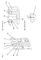
- Fig. 1 shows by way of example and schematically tread blocks 1 of a tread of a pneumatic vehicle tire, which is a suitable in particular for use in wintry driving conditions tires for passenger cars.
- the three profile blocks 1, which are shown completely, belong to a profile block row 1a running in the circumferential direction, which is separated by further circumferential grooves 2 from further profile positive elements, for example likewise profile block rows.
- the tread blocks 1 of the tread block row 1a are separated from each other by transverse grooves 3, in plan view substantially parallelogram-shaped and each provided with a number of cuts 4, which have a particular constant width, which is between 0.4 mm and 0.6 mm.
- three cuts 4 are provided per profile block 1, which run parallel to each other and at least substantially parallel to the transverse grooves 3 and their mutual distance and their distances to the transverse grooves 3 substantially match.
- the incisions 4 are seen in plan view of the tread blocks 1 as straight cuts.
- Fig. 2 shows a section through a tread block 1 along an incision 4 and a view of an incision wall 14.
- the opposite incision wall which is not shown, is located from the shown incision wall 14 at a distance which corresponds to the width of the incision 4, and is the incision wall 14 executed consistently.
- the incision 4 thus consists of two edge portions 4a, 4c and a central incision portion 4b, which extends to a depth T 1 , which is at least 65% of the tread depth T - this is the depth of the circumferential groove 2 - and at most the tread depth T corresponds.
- the two edge sections 4a and 4c are at the in Fig.
- one of the two edge sections 4a, 4c may have a smaller depth than the other, and in particular to to about 20% of the tread depth T rich.
- the deeper edge section extends in particular at least to a depth of 40% of the tread depth.
- the middle section 4b of the incision 4 extends over 30% to 80% of the longitudinal extent of the incision 4 in the profile block 1, the two edge sections 4a, 4c in particular over half of the remaining longitudinal extension, wherein the edge sections 4a, 4c can also have different lengths.
- Fig. 2 combined with Fig. 3 shows the incision 4 in the central incision portion 4b bounded by wall portions 14b, which are radially extending planar surfaces.
- the wall sections 14a, 14c in the edge sections 4a, 4c have a waveform in the radial direction with at least one corrugation peak and a wave trough, such that the corrugation peak (s) and the corrugation trough or troughs in the axial direction or parallel to Profile block surface run.
- the amplitude a 1 of the waveform between 0.5 mm and 2 mm, in particular about 1 mm, the wavelength l 1 depends on the radial extent of the incision portion 4a and 4c and is between 2 mm and 6 mm.
- the waveform comprises in particular at least one wavelength l 1 or 1.5 times the wavelength l 1 .
- the waveform on the block edge 11 has a constant amplitude a 1 and a constant wavelength l 1 .
- the amplitude a 1 of the waveform continuously decreases, except for the value zero, so that there is no longer any waveform at the boundary between the wall sections 14a / 14b or 14c / 14b in Fig. 2 is shown.
- the described wave form is preferably formed only in the lower edge section.
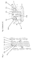
- FIG. 4 shows a plan view of some profile blocks 1 'of a profile block row 1'a in to Fig. 1 analog Presentation.
- the incisions 4 ' also have three incision sections 4'a, 4'b, 4'c, wherein the incision sections 4'a and 4'c are designed analogously to the incision sections 4a and 4c of the first embodiment, their wall sections 14'a and 14 'c have the described waveform with the amplitude a 1 and the wavelength l 1 at the block edges 11.
- the incision walls 14'b have either a wave form or a zigzag shape, which runs in each case at least over a complete wavelength l 1 and in particular is a multiple of half a wavelength (a wave crest / wave trough of the wave or zigzag shape) ,
- the wave crests and wave troughs extend in the radial direction, their height decreases continuously in the direction of the incision ground, so that at the incision reason the amplitude a 2 has decreased to zero and no wave form is present.
- the wavelength l 2 is between 3 mm and 7 mm, the amplitude a 2 between 1.5 mm and 3.5 mm.
- the amplitude of the wave or zigzag shape in the radial direction to the bottom of the incision portion remain constant.
- Notches made according to the invention may also be provided in shoulder-side tread blocks and have a peripheral edge opening in a circumferential groove, which is executed according to the invention.
Landscapes
- Engineering & Computer Science (AREA)
- Mechanical Engineering (AREA)
- Tires In General (AREA)
Abstract
Description
- Die Erfindung betrifft einen Fahrzeugluftreifen, insbesondere für den Einsatz unter winterlichen Fahrbedingungen, mit einem Laufstreifen mit zumindest einer in Umfangsrichtung umlaufenden und Profilblöcke aufweisenden Profilblockreihe, welche von zumindest einer Umfangsrille begrenzt ist und deren Profilblöcke jeweils mit einer Anzahl von zumindest im Wesentlichen in Laufstreifenquerrichtung verlaufenden Einschnitten geringer Breite versehen sind, welche Einschnitte jeweils einen tieferen Abschnitt und zumindest einen, an einer Blockflanke in eine Umfangsrille mündenden, seichteren Randabschnitt aufweisen.
- Es ist bekannt und üblich, Fahrzeugluftreifen, die für den Einsatz unter winterlichen Fahrbedingungen vorgesehen sind, mit Profilblöcken im Laufstreifen zu versehen, die jeweils eine Anzahl von Einschnitten mit einer Breite zwischen 0,4 mm und 0,6 mm aufweisen. Diese Einschnitte können auf unterschiedliche Weise ausgeführt sein. Es ist beispielsweise bekannt, in Draufsicht wellen-, zickzackförmig oder gerade verlaufende Einschnitte vorzusehen oder Einschnitte mit einer Kombination aus geraden, zickzack-oder wellenförmigen Abschnitten zu versehen. Aus der
EP 0 125 437 A1 ist es bekannt, in Draufsicht gewellt oder zickzackförmig verlaufende Einschnitte derart auszuführen, dass sie am Einschnittgrund eine kleinere Amplitude aufweisen als auf der Profilblockoberfläche. - Die Einschnitte in den Profilpositiven des Laufstreifens öffnen sich beim Aufbringen einer Umfangskraft im Latschdurchgang und bilden dadurch Griffkanten, die sich im komprimierten Schnee abstützen können und derart eine gute Kraftübertragung beim Bremsen und Beschleunigen des Fahrzeuges ermöglichen. Dieser Kanteneffekt ist ein wesentlicher Bestandteil des Griffpotentials eines Reifens. Darüber hinaus bewirken die Einschnitte beim Einfederungsprozess des Reifens während des Latschdurchganges eine erhöhte radiale Verformung der Profilpositive bzw. Profilblöcke. Diese macht sich durch ein seitliches Ausbauchen der Profilblöcke bei den Umfangsrillen bemerkbar und kann negative Auswirkungen auf den Abrieb, das Aquaplaningverhalten und den Rollwiderstand zeigen. Insbesondere in schmäleren Profilbändern oder Profilblockreihen werden die Einschnitte mit Randabschnitten versehen, die weniger tief ausgeführt sind, als der zwischen ihnen befindliche mittlere Einschnittabschnitt. Diese Randabschnitte können unterschiedlich tief ausgeführt sein, wodurch ein "balliges" Abreiben der Profilblöcke reduziert wird, welches bei gleich tiefen Randabschnitten auftreten kann.
- Der Erfindung liegt die Aufgabe zugrunde, Einschnitte im Laufstreifen von Reifen derart auszuführen, dass das oben erwähnte seitliche Ausbauchen der Profilblöcke verhindert bzw. deutlich reduziert wird.
- Gelöst wird die gestellte Aufgabe erfindungsgemäß dadurch, dass der Randabschnitt von Wandabschnitten begrenzt ist, welche eine Wellenform aufweisen, deren Wellenberg(e) und Wellental bzw. Wellentäler in axialer Richtung verlaufen und eine in Richtung zum tieferen Einschnittabschnitt abnehmende, insbesondere verschwindende Amplitude aufweisen.
- Durch diese spezielle wellenförmige Ausführung der Wandabschnitte in zumindest einem Randabschnitt mit einer von der Blockflanke in Richtung zum mittleren tieferen Abschnitt abnehmenden Amplitude wird der Profilblockrandbereich in radialer Richtung besonders vorteilhaft versteift, sodass das Einfedern und somit die Blockverformung in diesem Bereich reduziert werden. Der Profilblock erhält daher eine gleichmäßigere radiale Steifigkeit, wodurch das Abriebsbild infolge einer gleichmäßigeren Flächenpressung positiv beeinflusst wird. Die gleichmäßige Flächenpressung bewirkt zusätzlich eine Verbesserung der Wintereigenschaften, da die übertragbare Reibkraft sowohl von den großflächigen als auch von den lokalen Flächenpressungen in der Bodenaufstandsfläche, im Latsch, beeinflusst wird. Bereiche mit geringer Flächenpressung im Latsch könnten nicht so hohe Reibkräfte übertragen und dadurch Schlupf bewirken, wodurch die maximal übertragbare Reibkraft reduziert wäre. Die erhöhte radiale Steifigkeit der Profilblöcke reduziert ferner die unerwünschte Nutverengung, die bei einem seitlichen Ausbauchen der Profilblöcke im Latschdurchlauf erfolgen würde, sodass auch das Aquaplaning und die Schnee-Matsch-Eigenschaften des Reifens verbessert werden. Die reduzierte radiale Beweglichkeit der Profilblöcke im Latschdurchgang beeinflusst auch den Rollwiderstand des Reifens auf positive Weise. Durch die vom Randbereich zum mittleren Abschnitt in axialer Richtung hin abnehmende Amplitude der Wellenform wird die Versteifungswirkung in Richtung zur steiferen Blockmitte hin reduziert und somit eine besonders gute und effektive Öffnung des mittleren Einschnittabschnittes erreicht, wodurch die Wintereigenschaften des Reifens verbessert werden. Darüber hinaus bewirkt der spezielle Wellenverlauf des/der Randabschnitte(s) eine besondere Abstützung der durch die Einschnitte voneinander getrennten Profilblockelemente, derart, dass eine höhere Lateralkraft übertragen werden kann, was für die Handlingeigenschaften auf allen Untergründen von Vorteil ist.
- Je nach der Ausführung der Einschnitte lässt sich die radiale Steifigkeit der Profilblöcke auf unterschiedliche Weise beeinflussen. Bei einer möglichen Ausführungsvariante der Erfindung durchqueren die erfindungsgemäß ausgeführten Einschnitte die Profilblöcke und weisen zwei gleich tiefe Randabschnitte mit Wandabschnitten in Wellenform auf. Bei einer alternativen Ausführungsform der Erfindung sind die Einschnitte, welche die Profilblöcke durchqueren, mit zwei unterschiedlich tiefen Randabschnitten versehen. Bei dieser Ausführungsform ist es von Vorteil, wenn der tiefere Randabschnitt mit Wandabschnitten gemäß der Erfindung, demnach in Wellenform, versehen ist.
- Für eine optimale Versteifungswirkung ist es von Vorteil, wenn die Amplitude der Wellenform, an der die Umfangsrille begrenzenden Blockflanke ermittelt, 0,5 mm bis 2 mm und wenn die Wellenlänge der Wellenform 2 mm bis 6 mm beträgt. Für den Abstützungseffekt zwischen den von den Einschnitten begrenzten Profilblockelementen ist es vorteilhaft, wenn die Wellenform über zumindest eine Wellenlänge ausgebildet und ein Vielfaches einer halben Wellenlänge ist.
- Erfindungsgemäß ausgeführte Einschnitte können im tieferen Einschnittabschnitt von Wandabschnitten begrenzt sein, welche eine Wellen- oder Zickzackform aufweisen, deren Wellenberg(e) und Wellental bzw. Wellentäler in radialer Richtung verlaufen. Mit dieser Maßnahme lässt sich die Quersteifigkeit der Profilblöcke auf vorteilhafte Weise beeinflussen. Die Wellen- bzw. Zickzackform kann nun derart ausgeführt sein, dass die Amplitude zum Grund des Einschnittabschnittes abnimmt, wobei die Amplitude am Einschnittgrund auch Null sein kann. Alternativ ist eine Ausführungsform möglich, bei der die Amplitude der Wellen- bzw. Zickzackform konstant ist. Die Amplitude der Wellenform an der Profilblockoberseite beträgt insbesondere zwischen 1,5 mm und 3,5 mm, die Wellenlänge der Wellenform zwischen 3 mm und 7 mm. Dabei wird die Wellenform über zumindest eine Wellenlänge ausgebildet.
- Weitere Merkmale, Vorteile und Einzelheiten der Erfindung werden nun anhand der schematischen Zeichnung, die Ausführungsbeispiele der Erfindung darstellt, näher beschrieben. Dabei zeigen,
-
Fig. 1 eine Draufsicht auf einige Profilblöcke eines Laufstreifens eines Fahrzeugluftreifens, -
Fig. 2 einen entlang eines Einschnittes aufgeschnittenen Profilblock, in der durch die beiden Pfeile A inFig. 1 gekennzeichneten Ansicht, -
Fig. 3 eine Ansicht auf einen Teil eines Profilblockes ausFig. 1 gemäß den Pfeilen B ausFig. 1 , -
Fig. 4 eine Draufsicht auf einige Profilblöcke eines Laufstreifens eines Fahrzeugluftreifens mit einer weiteren Ausführungsvariante der Erfindung und -
Fig. 5 einen entlang eines Einschnittes aufgeschnittenen Profilblock ausFig. 4 , in der durch die Pfeile C inFig. 4 gekennzeichneten Ansicht. -
Fig. 1 zeigt beispielhaft und schematisch Profilblöcke 1 eines Laufstreifens eines Fahrzeugluftreifens, welcher ein insbesondere für den Einsatz unter winterlichen Fahrbedingungen geeigneter Reifen für Personenkraftwagen ist. Die drei komplett dargestellten Profilblöcke 1 gehören zu einer in Umfangsrichtung verlaufenden Profilblockreihe 1a, welche durch Umfangsrillen 2 von weiteren Profilpositiven, beispielsweise ebenfalls Profilblockreihen, getrennt ist. Die Profilblöcke 1 der Profilblockreihe 1a sind voneinander durch Quernuten 3 getrennt, in Draufsicht im Wesentlichen parallelogrammförmig und jeweils mit einer Anzahl von Einschnitten 4 versehen, welche eine insbesondere konstante Breite aufweisen, die zwischen 0,4 mm und 0,6 mm beträgt. Bei der dargestellten Ausführungsform sind pro Profilblock 1 drei Einschnitte 4 vorgesehen, welche jeweils parallel zueinander und zumindest im Wesentlichen parallel zu den Quernuten 3 verlaufen und deren gegenseitiger Abstand sowie deren Abstände zu den Quernuten 3 im Wesentlichen übereinstimmen. Bei neuem Reifen sind die Einschnitte 4 in Draufsicht auf die Profilblöcke 1 als gerade verlaufende Einschnitte zu sehen. -
Fig. 2 zeigt einen Schnitt durch einen Profilblock 1 entlang eines Einschnittes 4 und eine Ansicht einer Einschnittwand 14. Die gegenüberliegende Einschnittwand, welche nicht gezeigt ist, befindet sich von der gezeigten Einschnittwand 14 in einem Abstand, welcher der Breite des Einschnittes 4 entspricht, und ist zur Einschnittwand 14 übereinstimmend ausgeführt. Der Einschnitt 4 besteht somit aus zwei Randabschnitten 4a, 4c und einem mittleren Einschnittabschnitt 4b, welcher bis in eine Tiefe T1 reicht, die mindestens 65 % der Profiltiefe T beträgt - dies ist die Tiefe der Umfangsrille 2 - und maximal der Profiltiefe T entspricht. Die beiden Randabschnitte 4a und 4c sind bei der inFig. 2 gezeigten Ausführungsform gleich tief ausgeführt und reichen bis in eine Tiefe T2, welche geringer ist als T1 und insbesondere zwischen 20 % und 60 % der Profiltiefe T beträgt. Je nach Profilausgestaltung und Ausgestaltung der Profilblöcke 1 kann einer der beiden Randabschnitte 4a, 4c eine geringere Tiefe als der andere aufweisen und insbesondere bis auf etwa 20 % der Profiltiefe T reichen. Der tiefere Randabschnitt reicht insbesondere zumindest bis in eine Tiefe von 40% der Profiltiefe. Die Übergänge zwischen dem mittleren Abschnitt 4b und den beiden Randabschnitten 4a, 4c erfolgen in bekannter Weise über steile, nahezu in radialer Richtung verlaufende Übergangsflanken mit Übergangsrundungen. Der mittlere Abschnitt 4b des Einschnittes 4 verläuft über 30 % bis 80 % der Längserstreckung des Einschnittes 4 im Profilblock 1, die beiden Randabschnitte 4a, 4c insbesondere jeweils über die Hälfte der verbleibenden Längserstreckung, wobei die Randabschnitte 4a, 4c auch unterschiedliche Längen aufweisen können. Wie insbesondereFig. 2 in Verbindung mitFig. 3 zeigt, ist der Einschnitt 4 im mittleren Einschnittabschnitt 4b durch Wandabschnitte 14b begrenzt, die in radialer Richtung verlaufende ebene Flächen sind. Die Wandabschnitte 14a, 14c in den Randabschnitten 4a, 4c weisen in radialer Richtung eine Wellenform mit zumindest einem Wellenberg und einem Wellental auf, derart, dass der/die Wellenberg(e) und das Wellental bzw. die Wellentäler in axialer Richtung bzw. parallel zur Profilblockoberfläche verlaufen. An den Blockflanken 11 beträgt die Amplitude a1 der Wellenform zwischen 0,5 mm und 2 mm, insbesondere etwa 1 mm, die Wellenlänge l1 richtet sich nach der radialen Erstreckung des Einschnittabschnittes 4a bzw. 4c und beträgt zwischen 2 mm und 6 mm. Über die vorgesehene radiale Erstreckung der Wandabschnitte 14a bzw. 14c umfasst die Wellenform insbesondere zumindest eine Wellenlänge l1 bzw. das 1,5-Fache der Wellenlänge l1. Wie gezeigt, weist die Wellenform an der Blockflanke 11 eine konstante Amplitude a1 und eine konstante Wellenlänge l1 auf. In Richtung zum mittleren Einschnittabschnitt 4b bzw. zum mittleren Wandabschnitt 14b nimmt die Amplitude a1 der Wellenform kontinuierlich ab, bis auf den Wert Null, sodass an der Grenze zwischen den Wandabschnitten 14a/14b bzw. 14c/14b keine Wellenform mehr vorliegt, wie es inFig. 2 gezeigt ist. - Sind die Randabschnitte 4a, 4c unterschiedlich tief ausgeführt ist die beschriebene Wellenform vorzugsweise nur im tieferen Randabschnitt ausgebildet.
-
Fig. 4 und Fig. 5 zeigen eine weitere Ausführungsform der Erfindung.Fig. 4 zeigt eine Draufsicht auf einige Profilblöcke 1' einer Profilblockreihe 1'a in zuFig. 1 analoger Darstellung. Die durch Umfangsrillen 2 von benachbarten Profilpositiven getrennten Profilblöcke 1 weisen jeweils drei Einschnitte 4' auf, welche zueinander und zu den Quernuten 3 parallel bzw. im Wesentlichen parallel verlaufen. Die Einschnitte 4' weisen ebenfalls drei Einschnittabschnitte 4'a, 4'b, 4'c auf, wobei die Einschnittabschnitte 4'a und 4'c analog zu den Einschnittabschnitten 4a und 4c der ersten Ausführungsform ausgeführt sind, ihre Wandabschnitte 14'a und 14'c weisen die beschriebenen Wellenform mit der Amplitude a1 und der Wellenlänge l1 an den Blockflanken 11 auf. Im mittleren Einschnittabschnitt 4'b weisen die Einschnittwände 14'b entweder eine Wellenform oder eine Zickzackform auf, die jeweils zumindest über eine komplette Wellenlänge l1 verläuft und insbesondere ein Vielfaches einer halben Wellenlänge (ein Wellenberg/ein Wellental der Wellen- oder Zickzackform) ist. Die Wellenberge und Wellentäler erstrecken sich in radialer Richtung, ihre Höhe wird in Richtung Einschnittgrund kontinuierlich geringer, sodass am Einschnittgrund die Amplitude a2 auf Null abgenommen hat und keine Wellenform mehr vorliegt. An der Profiloberfläche und bei neuem Reifen beträgt die Wellenlänge l2 zwischen 3 mm und 7 mm, die Amplitude a2 zwischen 1,5 mm und 3,5 mm. Bei einer alternativen, nicht gezeigten Ausführungsform kann die Amplitude der Wellen- bzw. Zickzackform in radialer Richtung bis zum Grund des Einschnittabschnittes konstant bleiben. - Die Erfindung ist auf die dargestellten und beschriebenen Ausführungsformen nicht eingeschränkt. Erfindungsgemäß ausgeführte Einschnitte können auch in schulterseitigen Profilblöcken vorgesehen sein und einen in eine Umfangsrille mündenden Randabschnitt aufweisen, welcher gemäß der Erfindung ausgeführt ist.
-
- 1, 1'
- ..............Profilblock
- 1a, 1'a
- ..........Profilblockreihe
- 2
- ...................Umfangsrille
- 3
- ...................Quernut
- 4
- ...................Einschnitt
- 4a, 4'a
- ..........Randabschnitt
- 4b, 4'b
- ..........mittlerer Abschnitt
- 4c, 4'c
- ..........Randabschnitt
- 11
- .................Blockflanke
- 14, 14'
- ..........Einschnittwand
- 14a, 14'a
- ......Wandabschnitt
- 14b, 14'b
- ......Wandabschnitt
- 14c, 14'c
- ......Wandabschnitt
- T
- ..................Profiltiefe
- T1
- .................Tiefe
- T2
- .................Tiefe
- a1
- ..................Amplitude
- a2
- ..................Amplitude
- l1
- ..................Wellenlänge
- l2
- ..................Wellenlänge
Claims (12)
- Fahrzeugluftreifen, insbesondere für den Einsatz unter winterlichen Fahrbedingungen, mit einem Laufstreifen mit zumindest einer in Umfangsrichtung umlaufenden und Profilblöcke (1,1') aufweisenden Profilblockreihe (1a, 1'a), welche von zumindest einer Umfangsrille (2) begrenzt ist und deren Profilblöcke (1, 1') jeweils mit einer Anzahl von zumindest im Wesentlichen in Laufstreifenquerrichtung verlaufenden Einschnitten (4) geringer Breite versehen sind, welche jeweils einen tieferen Abschnitt (4b, 4'b) und zumindest einen an einer Blockflanke (11) in eine Umfangsrille (2) mündenden, seichteren Randabschnitt (4a, 4c, 4'a, 4'c) aufweisen,
dadurch gekennzeichnet,
dass der Randabschnitt (4a, 4c, 4'a, 4'c) von Wandabschnitten (14a, 14c, 14'a, 14'c) begrenzt ist, welche eine Wellenform aufweisen, deren Wellenberg(e) und/bzw. Wellental bzw. Wellentäler in axialer Richtung verlaufen und eine in Richtung tieferen Einschnittabschnitt (4b, 4'b) abnehmende, insbesondere verschwindende Amplitude (a1) aufweisen. - Fahrzeugluftreifen nach Anspruch 1, dadurch gekennzeichnet, dass die Einschnitte (4, 4') die Profilblöcke (1, 1') durchqueren und zwei gleich tiefe Randabschnitte (4a, 4c, 4'a, 4'c) mit Wandabschnitten (14a, 14c, 14'a, 14'c) in Wellenform aufweisen.
- Fahrzeugluftreifen nach Anspruch 1, dadurch gekennzeichnet, dass die Einschnitte die Profilblöcke durchqueren und zwei unterschiedlich tiefe Randabschnitte aufweisen, wobei der tiefere Randabschnitt mit Wandabschnitten in Wellenform versehen ist.
- Fahrzeugluftreifen nach einem der Ansprüche 1 bis 3, dadurch gekennzeichnet, dass die Amplitude (a1) der Wellenform an der die Umfangsrille (2) begrenzenden Blockflanke (11) 0,5 mm bis 2 mm beträgt.
- Fahrzeugluftreifen nach einem der Ansprüche 1 bis 4, dadurch gekennzeichnet, dass die Wellenlänge (l1) der Wellenform 2 mm bis 6 mm beträgt.
- Fahrzeugluftreifen nach einem der Ansprüche 1 bis 5, dadurch gekennzeichnet, dass die Wellenform über zumindest eine Wellenlänge (l1) ausgebildet und ein Vielfaches einer halben Wellenlänge (l1) ist.
- Fahrzeugluftreifen nach Anspruch 1, dadurch gekennzeichnet, dass der tiefere Einschnittabschnitt (4b, 4'b) von Wandabschnitten (14b, 14'b) begrenzt ist, welche eine Wellen- oder Zickzackform aufweisen, deren Wellenberg(e) und Wellental bzw. Wellentäler in radialer Richtung verlaufen.
- Fahrzeugluftreifen nach Anspruch 7, dadurch gekennzeichnet, dass die Amplitude (a2) der Wellen- bzw. Zickzackform zum Grund des Einschnittabschnittes (4b, 4'b) abnimmt, insbesondere derart, dass sie am Einschnittgrund Null ist.
- Fahrzeugluftreifen nach Anspruch 7, dadurch gekennzeichnet, dass die Amplitude (a2) der Wellen- bzw. Zickzackform zwischen der Profilblockoberseite und dem Grund des Einschnittabschnittes (4b, 4'b) konstant ist.
- Fahrzeugluftreifen nach Anspruch 8 oder 9, dadurch gekennzeichnet, dass die Amplitude (a2) der Wellenform an der Profilblockoberseite 1,5 mm bis 3,5 mm beträgt.
- Fahrzeugluftreifen nach Anspruch 8 oder 9, dadurch gekennzeichnet, dass die Wellenlänge (l2) der Wellenform 3 mm bis 7 mm beträgt.
- Fahrzeugluftreifen nach einem der Ansprüche 7 bis 11, dadurch gekennzeichnet, dass die Wellenform über zumindest eine Wellenlänge (l2) ausgebildet ist.
Applications Claiming Priority (1)
| Application Number | Priority Date | Filing Date | Title |
|---|---|---|---|
| DE201010061373 DE102010061373A1 (de) | 2010-12-20 | 2010-12-20 | Fahrzeugluftreifen |
Publications (2)
| Publication Number | Publication Date |
|---|---|
| EP2465708A1 true EP2465708A1 (de) | 2012-06-20 |
| EP2465708B1 EP2465708B1 (de) | 2014-08-13 |
Family
ID=45217195
Family Applications (1)
| Application Number | Title | Priority Date | Filing Date |
|---|---|---|---|
| EP20110188762 Active EP2465708B1 (de) | 2010-12-20 | 2011-11-11 | Fahrzeugluftreifen |
Country Status (2)
| Country | Link |
|---|---|
| EP (1) | EP2465708B1 (de) |
| DE (1) | DE102010061373A1 (de) |
Cited By (7)
| Publication number | Priority date | Publication date | Assignee | Title |
|---|---|---|---|---|
| JP2017052345A (ja) * | 2015-09-08 | 2017-03-16 | 東洋ゴム工業株式会社 | 空気入りタイヤ |
| JP2017052347A (ja) * | 2015-09-08 | 2017-03-16 | 東洋ゴム工業株式会社 | 空気入りタイヤ |
| WO2018103925A1 (de) * | 2016-12-07 | 2018-06-14 | Continental Reifen Deutschland Gmbh | Fahrzeugluftreifen |
| US10308078B2 (en) * | 2015-09-08 | 2019-06-04 | Toyo Tire Corporation | Pneumatic tire |
| EP3738793A4 (de) * | 2018-01-11 | 2021-08-25 | The Yokohama Rubber Co., Ltd. | Luftreifen |
| US11400764B2 (en) * | 2018-04-06 | 2022-08-02 | Sumitomo Rubber Industries Ltd. | Tire |
| CN115916556A (zh) * | 2020-06-30 | 2023-04-04 | 大陆轮胎德国有限公司 | 车辆充气轮胎 |
Citations (5)
| Publication number | Priority date | Publication date | Assignee | Title |
|---|---|---|---|---|
| EP0125437A1 (de) | 1983-04-12 | 1984-11-21 | MICHELIN & CIE (Compagnie Générale des Etablissements Michelin) Société dite: | Luftreifenlauffläche in deren Profilelemente wellenförmige Feineinschnitte vorgesehen sind |
| JPH11208221A (ja) * | 1998-01-23 | 1999-08-03 | Bridgestone Corp | 空気入りタイヤ |
| JP2000177329A (ja) * | 1998-12-14 | 2000-06-27 | Ohtsu Tire & Rubber Co Ltd :The | タイヤトレッド |
| WO2009077807A1 (en) * | 2007-12-19 | 2009-06-25 | Pirelli Tyre S.P.A. | Tyre for vehicle wheels |
| DE102009051278A1 (de) * | 2008-11-10 | 2010-05-12 | Toyo Tire & Rubber Co., Ltd. | Luftreifen |
-
2010
- 2010-12-20 DE DE201010061373 patent/DE102010061373A1/de not_active Withdrawn
-
2011
- 2011-11-11 EP EP20110188762 patent/EP2465708B1/de active Active
Patent Citations (5)
| Publication number | Priority date | Publication date | Assignee | Title |
|---|---|---|---|---|
| EP0125437A1 (de) | 1983-04-12 | 1984-11-21 | MICHELIN & CIE (Compagnie Générale des Etablissements Michelin) Société dite: | Luftreifenlauffläche in deren Profilelemente wellenförmige Feineinschnitte vorgesehen sind |
| JPH11208221A (ja) * | 1998-01-23 | 1999-08-03 | Bridgestone Corp | 空気入りタイヤ |
| JP2000177329A (ja) * | 1998-12-14 | 2000-06-27 | Ohtsu Tire & Rubber Co Ltd :The | タイヤトレッド |
| WO2009077807A1 (en) * | 2007-12-19 | 2009-06-25 | Pirelli Tyre S.P.A. | Tyre for vehicle wheels |
| DE102009051278A1 (de) * | 2008-11-10 | 2010-05-12 | Toyo Tire & Rubber Co., Ltd. | Luftreifen |
Cited By (8)
| Publication number | Priority date | Publication date | Assignee | Title |
|---|---|---|---|---|
| JP2017052345A (ja) * | 2015-09-08 | 2017-03-16 | 東洋ゴム工業株式会社 | 空気入りタイヤ |
| JP2017052347A (ja) * | 2015-09-08 | 2017-03-16 | 東洋ゴム工業株式会社 | 空気入りタイヤ |
| US10308078B2 (en) * | 2015-09-08 | 2019-06-04 | Toyo Tire Corporation | Pneumatic tire |
| WO2018103925A1 (de) * | 2016-12-07 | 2018-06-14 | Continental Reifen Deutschland Gmbh | Fahrzeugluftreifen |
| EP3738793A4 (de) * | 2018-01-11 | 2021-08-25 | The Yokohama Rubber Co., Ltd. | Luftreifen |
| US11584165B2 (en) | 2018-01-11 | 2023-02-21 | The Yokohama Rubber Co., Ltd. | Pneumatic tire |
| US11400764B2 (en) * | 2018-04-06 | 2022-08-02 | Sumitomo Rubber Industries Ltd. | Tire |
| CN115916556A (zh) * | 2020-06-30 | 2023-04-04 | 大陆轮胎德国有限公司 | 车辆充气轮胎 |
Also Published As
| Publication number | Publication date |
|---|---|
| DE102010061373A1 (de) | 2012-06-21 |
| EP2465708B1 (de) | 2014-08-13 |
Similar Documents
| Publication | Publication Date | Title |
|---|---|---|
| EP2465708B1 (de) | Fahrzeugluftreifen | |
| EP2353884B1 (de) | Fahrzeugluftreifen | |
| EP2460672B1 (de) | Fahrzeugluftreifen | |
| EP2159080B1 (de) | Fahrzeugluftreifen | |
| DE102010060946A1 (de) | Fahrzeugluftreifen | |
| EP2803501B1 (de) | Fahrzeugluftreifen | |
| WO2013064300A1 (de) | Fahrzeugluftreifen | |
| EP2217455B1 (de) | Fahrzeugluftreifen | |
| EP3383671B1 (de) | Fahrzeugluftreifen | |
| EP3554855B1 (de) | Fahrzeugluftreifen | |
| EP2138327B1 (de) | Laufflächenprofil für einen Fahrzeugluftreifen | |
| EP3441241B1 (de) | Fahrzeugluftreifen | |
| EP3446892B1 (de) | Fahrzeugluftreifen | |
| EP2990235B1 (de) | Fahrzeugluftreifen | |
| EP3551477B1 (de) | Fahrzeugluftreifen | |
| WO2017092897A1 (de) | Fahrzeugluftreifen | |
| EP1529662A1 (de) | Fahrzeugluftreifen | |
| EP2138329B1 (de) | Laufflächenprofil für einen Fahrzeugluftreifen | |
| EP3079925B1 (de) | Fahrzeugluftreifen | |
| DE19711852A1 (de) | Fahrzeugluftreifen | |
| EP2648925B1 (de) | Fahrzeugluftreifen | |
| EP2000329B1 (de) | Fahrzeugluftreifen | |
| EP2504180A1 (de) | Fahrzeugluftreifen | |
| EP2138328B1 (de) | Fahrzeugluftreifen | |
| EP2979903B1 (de) | Fahrzeugluftreifen |
Legal Events
| Date | Code | Title | Description |
|---|---|---|---|
| PUAI | Public reference made under article 153(3) epc to a published international application that has entered the european phase |
Free format text: ORIGINAL CODE: 0009012 |
|
| AK | Designated contracting states |
Kind code of ref document: A1 Designated state(s): AL AT BE BG CH CY CZ DE DK EE ES FI FR GB GR HR HU IE IS IT LI LT LU LV MC MK MT NL NO PL PT RO RS SE SI SK SM TR |
|
| AX | Request for extension of the european patent |
Extension state: BA ME |
|
| 17P | Request for examination filed |
Effective date: 20121220 |
|
| GRAP | Despatch of communication of intention to grant a patent |
Free format text: ORIGINAL CODE: EPIDOSNIGR1 |
|
| INTG | Intention to grant announced |
Effective date: 20140422 |
|
| GRAS | Grant fee paid |
Free format text: ORIGINAL CODE: EPIDOSNIGR3 |
|
| GRAA | (expected) grant |
Free format text: ORIGINAL CODE: 0009210 |
|
| AK | Designated contracting states |
Kind code of ref document: B1 Designated state(s): AL AT BE BG CH CY CZ DE DK EE ES FI FR GB GR HR HU IE IS IT LI LT LU LV MC MK MT NL NO PL PT RO RS SE SI SK SM TR |
|
| REG | Reference to a national code |
Ref country code: GB Ref legal event code: FG4D Free format text: NOT ENGLISH |
|
| REG | Reference to a national code |
Ref country code: AT Ref legal event code: REF Ref document number: 681984 Country of ref document: AT Kind code of ref document: T Effective date: 20140815 Ref country code: CH Ref legal event code: EP |
|
| REG | Reference to a national code |
Ref country code: IE Ref legal event code: FG4D Free format text: LANGUAGE OF EP DOCUMENT: GERMAN |
|
| REG | Reference to a national code |
Ref country code: DE Ref legal event code: R096 Ref document number: 502011004018 Country of ref document: DE Effective date: 20140925 |
|
| REG | Reference to a national code |
Ref country code: SE Ref legal event code: TRGR |
|
| REG | Reference to a national code |
Ref country code: NL Ref legal event code: VDEP Effective date: 20140813 |
|
| REG | Reference to a national code |
Ref country code: LT Ref legal event code: MG4D |
|
| PG25 | Lapsed in a contracting state [announced via postgrant information from national office to epo] |
Ref country code: FI Free format text: LAPSE BECAUSE OF FAILURE TO SUBMIT A TRANSLATION OF THE DESCRIPTION OR TO PAY THE FEE WITHIN THE PRESCRIBED TIME-LIMIT Effective date: 20140813 Ref country code: NO Free format text: LAPSE BECAUSE OF FAILURE TO SUBMIT A TRANSLATION OF THE DESCRIPTION OR TO PAY THE FEE WITHIN THE PRESCRIBED TIME-LIMIT Effective date: 20141113 Ref country code: ES Free format text: LAPSE BECAUSE OF FAILURE TO SUBMIT A TRANSLATION OF THE DESCRIPTION OR TO PAY THE FEE WITHIN THE PRESCRIBED TIME-LIMIT Effective date: 20140813 Ref country code: GR Free format text: LAPSE BECAUSE OF FAILURE TO SUBMIT A TRANSLATION OF THE DESCRIPTION OR TO PAY THE FEE WITHIN THE PRESCRIBED TIME-LIMIT Effective date: 20141114 Ref country code: PT Free format text: LAPSE BECAUSE OF FAILURE TO SUBMIT A TRANSLATION OF THE DESCRIPTION OR TO PAY THE FEE WITHIN THE PRESCRIBED TIME-LIMIT Effective date: 20141215 Ref country code: LT Free format text: LAPSE BECAUSE OF FAILURE TO SUBMIT A TRANSLATION OF THE DESCRIPTION OR TO PAY THE FEE WITHIN THE PRESCRIBED TIME-LIMIT Effective date: 20140813 Ref country code: BG Free format text: LAPSE BECAUSE OF FAILURE TO SUBMIT A TRANSLATION OF THE DESCRIPTION OR TO PAY THE FEE WITHIN THE PRESCRIBED TIME-LIMIT Effective date: 20141113 |
|
| PG25 | Lapsed in a contracting state [announced via postgrant information from national office to epo] |
Ref country code: HR Free format text: LAPSE BECAUSE OF FAILURE TO SUBMIT A TRANSLATION OF THE DESCRIPTION OR TO PAY THE FEE WITHIN THE PRESCRIBED TIME-LIMIT Effective date: 20140813 Ref country code: RS Free format text: LAPSE BECAUSE OF FAILURE TO SUBMIT A TRANSLATION OF THE DESCRIPTION OR TO PAY THE FEE WITHIN THE PRESCRIBED TIME-LIMIT Effective date: 20140813 Ref country code: IS Free format text: LAPSE BECAUSE OF FAILURE TO SUBMIT A TRANSLATION OF THE DESCRIPTION OR TO PAY THE FEE WITHIN THE PRESCRIBED TIME-LIMIT Effective date: 20141213 Ref country code: CY Free format text: LAPSE BECAUSE OF FAILURE TO SUBMIT A TRANSLATION OF THE DESCRIPTION OR TO PAY THE FEE WITHIN THE PRESCRIBED TIME-LIMIT Effective date: 20140813 Ref country code: LV Free format text: LAPSE BECAUSE OF FAILURE TO SUBMIT A TRANSLATION OF THE DESCRIPTION OR TO PAY THE FEE WITHIN THE PRESCRIBED TIME-LIMIT Effective date: 20140813 |
|
| PG25 | Lapsed in a contracting state [announced via postgrant information from national office to epo] |
Ref country code: NL Free format text: LAPSE BECAUSE OF FAILURE TO SUBMIT A TRANSLATION OF THE DESCRIPTION OR TO PAY THE FEE WITHIN THE PRESCRIBED TIME-LIMIT Effective date: 20140813 |
|
| PG25 | Lapsed in a contracting state [announced via postgrant information from national office to epo] |
Ref country code: SK Free format text: LAPSE BECAUSE OF FAILURE TO SUBMIT A TRANSLATION OF THE DESCRIPTION OR TO PAY THE FEE WITHIN THE PRESCRIBED TIME-LIMIT Effective date: 20140813 Ref country code: RO Free format text: LAPSE BECAUSE OF FAILURE TO SUBMIT A TRANSLATION OF THE DESCRIPTION OR TO PAY THE FEE WITHIN THE PRESCRIBED TIME-LIMIT Effective date: 20140813 Ref country code: DK Free format text: LAPSE BECAUSE OF FAILURE TO SUBMIT A TRANSLATION OF THE DESCRIPTION OR TO PAY THE FEE WITHIN THE PRESCRIBED TIME-LIMIT Effective date: 20140813 Ref country code: IT Free format text: LAPSE BECAUSE OF FAILURE TO SUBMIT A TRANSLATION OF THE DESCRIPTION OR TO PAY THE FEE WITHIN THE PRESCRIBED TIME-LIMIT Effective date: 20140813 Ref country code: EE Free format text: LAPSE BECAUSE OF FAILURE TO SUBMIT A TRANSLATION OF THE DESCRIPTION OR TO PAY THE FEE WITHIN THE PRESCRIBED TIME-LIMIT Effective date: 20140813 Ref country code: CZ Free format text: LAPSE BECAUSE OF FAILURE TO SUBMIT A TRANSLATION OF THE DESCRIPTION OR TO PAY THE FEE WITHIN THE PRESCRIBED TIME-LIMIT Effective date: 20140813 |
|
| REG | Reference to a national code |
Ref country code: DE Ref legal event code: R097 Ref document number: 502011004018 Country of ref document: DE |
|
| PG25 | Lapsed in a contracting state [announced via postgrant information from national office to epo] |
Ref country code: PL Free format text: LAPSE BECAUSE OF FAILURE TO SUBMIT A TRANSLATION OF THE DESCRIPTION OR TO PAY THE FEE WITHIN THE PRESCRIBED TIME-LIMIT Effective date: 20140813 |
|
| PLBE | No opposition filed within time limit |
Free format text: ORIGINAL CODE: 0009261 |
|
| STAA | Information on the status of an ep patent application or granted ep patent |
Free format text: STATUS: NO OPPOSITION FILED WITHIN TIME LIMIT |
|
| PG25 | Lapsed in a contracting state [announced via postgrant information from national office to epo] |
Ref country code: BE Free format text: LAPSE BECAUSE OF NON-PAYMENT OF DUE FEES Effective date: 20141130 Ref country code: MC Free format text: LAPSE BECAUSE OF FAILURE TO SUBMIT A TRANSLATION OF THE DESCRIPTION OR TO PAY THE FEE WITHIN THE PRESCRIBED TIME-LIMIT Effective date: 20140813 Ref country code: LU Free format text: LAPSE BECAUSE OF FAILURE TO SUBMIT A TRANSLATION OF THE DESCRIPTION OR TO PAY THE FEE WITHIN THE PRESCRIBED TIME-LIMIT Effective date: 20141111 |
|
| 26N | No opposition filed |
Effective date: 20150515 |
|
| REG | Reference to a national code |
Ref country code: IE Ref legal event code: MM4A |
|
| PG25 | Lapsed in a contracting state [announced via postgrant information from national office to epo] |
Ref country code: IE Free format text: LAPSE BECAUSE OF NON-PAYMENT OF DUE FEES Effective date: 20141111 |
|
| REG | Reference to a national code |
Ref country code: FR Ref legal event code: PLFP Year of fee payment: 5 |
|
| PG25 | Lapsed in a contracting state [announced via postgrant information from national office to epo] |
Ref country code: SI Free format text: LAPSE BECAUSE OF FAILURE TO SUBMIT A TRANSLATION OF THE DESCRIPTION OR TO PAY THE FEE WITHIN THE PRESCRIBED TIME-LIMIT Effective date: 20140813 |
|
| PG25 | Lapsed in a contracting state [announced via postgrant information from national office to epo] |
Ref country code: SM Free format text: LAPSE BECAUSE OF FAILURE TO SUBMIT A TRANSLATION OF THE DESCRIPTION OR TO PAY THE FEE WITHIN THE PRESCRIBED TIME-LIMIT Effective date: 20140813 |
|
| GBPC | Gb: european patent ceased through non-payment of renewal fee |
Effective date: 20151111 |
|
| PG25 | Lapsed in a contracting state [announced via postgrant information from national office to epo] |
Ref country code: TR Free format text: LAPSE BECAUSE OF FAILURE TO SUBMIT A TRANSLATION OF THE DESCRIPTION OR TO PAY THE FEE WITHIN THE PRESCRIBED TIME-LIMIT Effective date: 20140813 Ref country code: MT Free format text: LAPSE BECAUSE OF FAILURE TO SUBMIT A TRANSLATION OF THE DESCRIPTION OR TO PAY THE FEE WITHIN THE PRESCRIBED TIME-LIMIT Effective date: 20140813 Ref country code: HU Free format text: LAPSE BECAUSE OF FAILURE TO SUBMIT A TRANSLATION OF THE DESCRIPTION OR TO PAY THE FEE WITHIN THE PRESCRIBED TIME-LIMIT; INVALID AB INITIO Effective date: 20111111 |
|
| PG25 | Lapsed in a contracting state [announced via postgrant information from national office to epo] |
Ref country code: GB Free format text: LAPSE BECAUSE OF NON-PAYMENT OF DUE FEES Effective date: 20151111 |
|
| REG | Reference to a national code |
Ref country code: FR Ref legal event code: PLFP Year of fee payment: 6 |
|
| REG | Reference to a national code |
Ref country code: FR Ref legal event code: PLFP Year of fee payment: 7 |
|
| PG25 | Lapsed in a contracting state [announced via postgrant information from national office to epo] |
Ref country code: MK Free format text: LAPSE BECAUSE OF FAILURE TO SUBMIT A TRANSLATION OF THE DESCRIPTION OR TO PAY THE FEE WITHIN THE PRESCRIBED TIME-LIMIT Effective date: 20140813 |
|
| PG25 | Lapsed in a contracting state [announced via postgrant information from national office to epo] |
Ref country code: AL Free format text: LAPSE BECAUSE OF FAILURE TO SUBMIT A TRANSLATION OF THE DESCRIPTION OR TO PAY THE FEE WITHIN THE PRESCRIBED TIME-LIMIT Effective date: 20140813 |
|
| PGFP | Annual fee paid to national office [announced via postgrant information from national office to epo] |
Ref country code: FR Payment date: 20181123 Year of fee payment: 8 Ref country code: CH Payment date: 20181120 Year of fee payment: 8 |
|
| REG | Reference to a national code |
Ref country code: CH Ref legal event code: PL |
|
| PG25 | Lapsed in a contracting state [announced via postgrant information from national office to epo] |
Ref country code: CH Free format text: LAPSE BECAUSE OF NON-PAYMENT OF DUE FEES Effective date: 20191130 Ref country code: LI Free format text: LAPSE BECAUSE OF NON-PAYMENT OF DUE FEES Effective date: 20191130 |
|
| REG | Reference to a national code |
Ref country code: AT Ref legal event code: MM01 Ref document number: 681984 Country of ref document: AT Kind code of ref document: T Effective date: 20191111 |
|
| PG25 | Lapsed in a contracting state [announced via postgrant information from national office to epo] |
Ref country code: FR Free format text: LAPSE BECAUSE OF NON-PAYMENT OF DUE FEES Effective date: 20191130 |
|
| PG25 | Lapsed in a contracting state [announced via postgrant information from national office to epo] |
Ref country code: AT Free format text: LAPSE BECAUSE OF NON-PAYMENT OF DUE FEES Effective date: 20191111 |
|
| REG | Reference to a national code |
Ref country code: DE Ref legal event code: R081 Ref document number: 502011004018 Country of ref document: DE Owner name: CONTINENTAL REIFEN DEUTSCHLAND GMBH, DE Free format text: FORMER OWNER: CONTINENTAL REIFEN DEUTSCHLAND GMBH, 30165 HANNOVER, DE |
|
| PGFP | Annual fee paid to national office [announced via postgrant information from national office to epo] |
Ref country code: SE Payment date: 20241120 Year of fee payment: 14 |
|
| PGFP | Annual fee paid to national office [announced via postgrant information from national office to epo] |
Ref country code: DE Payment date: 20251130 Year of fee payment: 15 |