EP2465694A1 - Bookbinding system using unfixed toner image as adhesive - Google Patents
Bookbinding system using unfixed toner image as adhesive Download PDFInfo
- Publication number
- EP2465694A1 EP2465694A1 EP11191643A EP11191643A EP2465694A1 EP 2465694 A1 EP2465694 A1 EP 2465694A1 EP 11191643 A EP11191643 A EP 11191643A EP 11191643 A EP11191643 A EP 11191643A EP 2465694 A1 EP2465694 A1 EP 2465694A1
- Authority
- EP
- European Patent Office
- Prior art keywords
- sheet
- toner image
- adhesive
- adhesive toner
- image forming
- Prior art date
- Legal status (The legal status is an assumption and is not a legal conclusion. Google has not performed a legal analysis and makes no representation as to the accuracy of the status listed.)
- Granted
Links
- 239000000853 adhesive Substances 0.000 title claims abstract description 282
- 230000001070 adhesive effect Effects 0.000 title claims abstract description 282
- 239000002699 waste material Substances 0.000 claims description 61
- 230000033228 biological regulation Effects 0.000 claims description 42
- 238000004140 cleaning Methods 0.000 claims description 30
- 230000002265 prevention Effects 0.000 claims description 23
- 238000000034 method Methods 0.000 claims description 19
- 230000010355 oscillation Effects 0.000 claims description 12
- 238000000926 separation method Methods 0.000 claims description 11
- 230000008021 deposition Effects 0.000 claims description 10
- 230000008569 process Effects 0.000 claims description 9
- 238000011144 upstream manufacturing Methods 0.000 claims description 7
- 238000003825 pressing Methods 0.000 claims description 6
- 238000012546 transfer Methods 0.000 description 37
- 238000010438 heat treatment Methods 0.000 description 31
- 108091008695 photoreceptors Proteins 0.000 description 29
- 230000015572 biosynthetic process Effects 0.000 description 11
- 238000001514 detection method Methods 0.000 description 8
- 239000011230 binding agent Substances 0.000 description 4
- 230000008859 change Effects 0.000 description 4
- 239000003086 colorant Substances 0.000 description 3
- 230000006870 function Effects 0.000 description 3
- RYGMFSIKBFXOCR-UHFFFAOYSA-N Copper Chemical compound [Cu] RYGMFSIKBFXOCR-UHFFFAOYSA-N 0.000 description 2
- 230000008901 benefit Effects 0.000 description 2
- 230000001427 coherent effect Effects 0.000 description 2
- 239000010949 copper Substances 0.000 description 2
- 229910052802 copper Inorganic materials 0.000 description 2
- 229910052736 halogen Inorganic materials 0.000 description 2
- 150000002367 halogens Chemical class 0.000 description 2
- 239000000463 material Substances 0.000 description 2
- 230000007246 mechanism Effects 0.000 description 2
- 239000002245 particle Substances 0.000 description 2
- 239000004677 Nylon Substances 0.000 description 1
- 206010033546 Pallor Diseases 0.000 description 1
- 239000004642 Polyimide Substances 0.000 description 1
- 239000004809 Teflon Substances 0.000 description 1
- 229920006362 Teflon® Polymers 0.000 description 1
- 239000000919 ceramic Substances 0.000 description 1
- 239000004020 conductor Substances 0.000 description 1
- 230000007423 decrease Effects 0.000 description 1
- 230000000593 degrading effect Effects 0.000 description 1
- 238000011161 development Methods 0.000 description 1
- 238000005530 etching Methods 0.000 description 1
- 239000011521 glass Substances 0.000 description 1
- 238000009413 insulation Methods 0.000 description 1
- 238000002844 melting Methods 0.000 description 1
- 230000008018 melting Effects 0.000 description 1
- 238000012986 modification Methods 0.000 description 1
- 230000004048 modification Effects 0.000 description 1
- 229920001778 nylon Polymers 0.000 description 1
- 229920001721 polyimide Polymers 0.000 description 1
- 238000012805 post-processing Methods 0.000 description 1
- 238000004064 recycling Methods 0.000 description 1
- 229920005989 resin Polymers 0.000 description 1
- 239000011347 resin Substances 0.000 description 1
- 238000007790 scraping Methods 0.000 description 1
- 229910052710 silicon Inorganic materials 0.000 description 1
- 239000010703 silicon Substances 0.000 description 1
- 229910001220 stainless steel Inorganic materials 0.000 description 1
- 239000010935 stainless steel Substances 0.000 description 1
- 230000000153 supplemental effect Effects 0.000 description 1
Images





Classifications
-
- G—PHYSICS
- G03—PHOTOGRAPHY; CINEMATOGRAPHY; ANALOGOUS TECHNIQUES USING WAVES OTHER THAN OPTICAL WAVES; ELECTROGRAPHY; HOLOGRAPHY
- G03G—ELECTROGRAPHY; ELECTROPHOTOGRAPHY; MAGNETOGRAPHY
- G03G15/00—Apparatus for electrographic processes using a charge pattern
- G03G15/65—Apparatus which relate to the handling of copy material
- G03G15/6538—Devices for collating sheet copy material, e.g. sorters, control, copies in staples form
- G03G15/6541—Binding sets of sheets, e.g. by stapling, glueing
-
- B—PERFORMING OPERATIONS; TRANSPORTING
- B42—BOOKBINDING; ALBUMS; FILES; SPECIAL PRINTED MATTER
- B42C—BOOKBINDING
- B42C1/00—Collating or gathering sheets combined with processes for permanently attaching together sheets or signatures or for interposing inserts
- B42C1/12—Machines for both collating or gathering and permanently attaching together the sheets or signatures
-
- B—PERFORMING OPERATIONS; TRANSPORTING
- B42—BOOKBINDING; ALBUMS; FILES; SPECIAL PRINTED MATTER
- B42C—BOOKBINDING
- B42C9/00—Applying glue or adhesive peculiar to bookbinding
- B42C9/0081—Applying glue or adhesive peculiar to bookbinding applying adhesive to individual sheets for binding them together
-
- G—PHYSICS
- G03—PHOTOGRAPHY; CINEMATOGRAPHY; ANALOGOUS TECHNIQUES USING WAVES OTHER THAN OPTICAL WAVES; ELECTROGRAPHY; HOLOGRAPHY
- G03G—ELECTROGRAPHY; ELECTROPHOTOGRAPHY; MAGNETOGRAPHY
- G03G15/00—Apparatus for electrographic processes using a charge pattern
- G03G15/65—Apparatus which relate to the handling of copy material
- G03G15/6538—Devices for collating sheet copy material, e.g. sorters, control, copies in staples form
- G03G15/6541—Binding sets of sheets, e.g. by stapling, glueing
- G03G15/6544—Details about the binding means or procedure
-
- G—PHYSICS
- G03—PHOTOGRAPHY; CINEMATOGRAPHY; ANALOGOUS TECHNIQUES USING WAVES OTHER THAN OPTICAL WAVES; ELECTROGRAPHY; HOLOGRAPHY
- G03G—ELECTROGRAPHY; ELECTROPHOTOGRAPHY; MAGNETOGRAPHY
- G03G2215/00—Apparatus for electrophotographic processes
- G03G2215/00362—Apparatus for electrophotographic processes relating to the copy medium handling
- G03G2215/00789—Adding properties or qualities to the copy medium
- G03G2215/00822—Binder, e.g. glueing device
- G03G2215/00835—Toner binding
-
- G—PHYSICS
- G03—PHOTOGRAPHY; CINEMATOGRAPHY; ANALOGOUS TECHNIQUES USING WAVES OTHER THAN OPTICAL WAVES; ELECTROGRAPHY; HOLOGRAPHY
- G03G—ELECTROGRAPHY; ELECTROPHOTOGRAPHY; MAGNETOGRAPHY
- G03G2215/00—Apparatus for electrophotographic processes
- G03G2215/00362—Apparatus for electrophotographic processes relating to the copy medium handling
- G03G2215/00919—Special copy medium handling apparatus
- G03G2215/00936—Bookbinding
Definitions
- the present invention relates to an integrated bookbinding system to perform steps from image formation to bookbinding.
- a bookbinding system in which a plurality of sheets on which images are formed by an image forming apparatus is bundled into a sheet bundle, and an adhesive is applied to a spine of the sheet bundle to produce a complete book.
- JP-2008-55677-A discloses a bookbinding system that forms an adhesive toner image on a binding edge portion of each sheet using the image forming apparatus.
- a regular toner image is transferred to the sheet based on image data as well as the adhesive toner image is transferred to a portion corresponding to the spine edge of the sheet.
- the sheets on which these toner images are formed are conveyed to a fixing device, and are sequentially sent to a bookbinding processor after the toner images are fixed onto each sheet.
- the plurality of sheets conveyed to the bookbinding processor forms a sheet bundle stacked on a stack section.
- a spine edge portion of the sheet bundle is coated with an adhesive heated by a heater.
- the adhesive toner image is heated and softened by the heated adhesive to thus serve as an adhesive to attach adjacent sheets to each other.
- the adjacent sheets are attached to each other by the adhesive toner image and the adhesive.
- the present invention provides an improved bookbinding system capable of attach the sheets to each other by use of adhesive toner image only.
- the inventors of the present invention have found that by attaching the adjacent sheets with an unfixed toner image, the sheets are more firmly attached to each other than when using the toner image after fixation.
- the present invention provides, therefore, an optimal bookbinding system having an adhesive toner image forming unit to form an adhesive toner image on a sheet; a fixing device to fix the toner image onto the sheet; and a sheet stacker to load the sheet which has passed through the fixing device.
- the sheet bundle stacked on the sheet stacker is adhered to produce a complete book.
- the optimal bookbinding system further includes an adhesive toner image forming unit and a heater.
- the adhesive toner image forming unit forms an adhesive toner image on an area corresponding to a spine of the complete book.
- the heater heats the unfixed adhesive toner image formed on each sheet of the sheet bundle stacked on the sheet stacker, in which the adhesive toner image on the sheet stacked on the sheet stacker is the unfixed toner image.
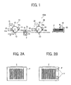
- FIG. 1 is a general configuration of a bookbinding system according to a first embodiment of the present invention
- FIG. 2A is a view illustrating a sheet after having passed an image forming unit
- FIG. 2B is a view illustrating a sheet after having passed an adhesive toner image forming unit
- FIG. 3 is a general configuration of a heater
- FIGS. 4A and 4B are explanatory views illustrating operation of the heater
- FIG. 5 is a view illustrating a pressing area of the heater relative to a bundle of sheets.
- FIG 6 is a general configuration of a modified example of the heater
- FIG. 7 is a graph showing a relation between the power-on time, thickness of the adhesive toner image, and adhesion strength between sheets;
- FIG 8 is a general configuration of a bookbinding system according to a second embodiment of the present invention.
- Fig. 9 is a general configuration of a heater related to the bookbinding system according to the second embodiment of the present invention.
- FIGS. 10A to 10C are views illustrating separating operation of a separation unit to separate a pressure roller from a heating roller
- FIG. 11 is a modified example of the separation unit
- FIG. 12 is another modified example of the separation unit
- FIGS. 13(a) through 13(d) are views illustrating operation when a sheet on which a toner image and an adhesive toner image are transferred passes through a fixing nip;
- FIG. 14 is a modified example of a bookbinding system according to the second embodiment of the present invention.
- FIG 15 is a general configuration of a bookbinding system according to a third embodiment of the present invention.
- FIG. 16 is an oblique view illustrating an image forming unit and a waste toner conveyance path
- FIG 17 is a general configuration of a main part of a bookbinding system according to a fourth embodiment of the present invention.
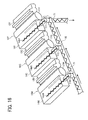
- FIG. 18 is a general configuration of a main part of a binding device
- FIGS. 19(a) and 19(b) are views illustrating a main part around a leading end stopper
- FIG. 20 is an enlarged view illustrating the part around the sheet stacker
- FIG. 21 is a view illustrating the part around the adhesive toner image forming unit seen from a sheet conveyance direction
- FIG. 22 is a plan view of a toner regulation plate
- FIG. 23 is a plan view of the toner regulation plate including an oscillation unit
- FIGS. 24A to 24C are views illustrating contacting and separating operation of the heater
- FIGS. 25 is an explanatory view illustrating operation of a sheet contact prevention plate
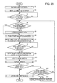
- FIG. 26 is a control flowchart to create a complete booklet
- FIG 27 is a view illustrating a modified example of the toner regulation plate.
- FIG 28 is a view illustrating a structure in which a cleaning device for the toner regulation plate is provided.
- FIG. 1 is a general configuration of a bookbinding system 100A according to a first embodiment of the present invention.
- the bookbinding system includes, in a sheet conveyance direction (that is, in the direction of arrow A in the figure), an image forming unit 10, a fixing device 2, an adhesive toner image forming unit 20, a sheet stacker 30, and a heater 40.
- the above image forming unit 10, the fixing device 2, the adhesive toner image forming unit 20, the sheet stacker 30, and the heater 40 may be included in an image forming apparatus.
- the adhesive toner image forming unit 20 and the sheet stacker 30 may be provided in another post-processing device separate from the image forming apparatus where the latter is a multifunction printer or a product printing device.
- the image forming unit 10 includes a photoreceptor 11 as an image carrier rotating in the direction indicated by an arrow in the figure, a charger 15, an exposure unit 16, a developing device 12, a transfer device 13, and a cleaning device 14, which are sequentially disposed around the photoreceptor 11.
- the charger 15 being a charging means is disposed in contact or non-contact with the photoreceptor 11 and serves to apply bias voltage to the photoreceptor 11 so that the photoreceptor 11 is charged in a predetermined polarity and at a predetermined electrical potential.
- the exposure unit 16 as a latent image forming means uses a LD or an LED as a light emitting device and radiates light L modulated by the image data to the photoreceptor 11 charged by the charger 15, thereby forming an electrostatic latent image on the photoreceptor 11.
- the developing device 12 as a developing means includes a developer carrier 12a and a built-in magnet roller fixed inside the developer carrier 12a, and holds the developer on the developer carrier 12a.
- two-component developer formed of toner and carrier and two-component electromagnetic brush developing method suitable for the type of developer are used.
- one-component developing method without using carrier can also be used.
- a developing bias supply source applies voltage to the developer carrier 12a.
- the transfer device 13 as a transfer means contacts, in a transfer operation, a surface of the photoreceptor 11 at a predetermined pressing force and applies voltage thereto, thereby transferring a toner image on the surface of the photoreceptor 11 at a transfer nip between the photoreceptor 11 and the transfer device 13.
- a transfer roller is used as a transfer device 13; however, a corotron or a transfer belt may be used as a transfer device.
- the cleaning device 14 as a cleaning means serves to remove residual toner on the photoreceptor 11 after transferring operation by the transfer device 13.
- the cleaning device 14 includes a cleaning blade 14a to remove residual toner on the photoreceptor 11 and a toner conveyer 14b to convey the cleaned toner or waste toner to a waste toner bottle.
- the cleaning blade 14a is contacted, with pressure, the rotating photoreceptor 11 so that the residual toner is removed from the photoreceptor 11.
- the toner removed from the photoreceptor 11 by the cleaning blade 14a is collected in the waste toner bottle, not shown, as waste toner.
- the fixing device 2 serving to fix a toner image on the sheet is disposed downstream in the sheet P conveyance direction than the transfer device 13.
- the fixing device 2 includes a heat roller 2b as a heating member to include a heat source such as a halogen lamp, not shown, and a pressure roller 2a as a nip forming member to press the heat roller 2b to form a fixing nip.
- the adhesive toner image forming unit 20 includes a configuration similar to that of the image forming unit 10. Specifically, the adhesive toner image forming unit 20 includes a photoreceptor 21 as an image carrier rotating in the direction indicated by an arrow in the figure, and a charger 25, an exposure unit 26, a developing device 22, a transfer device 23, and a cleaning device 24 which are sequentially disposed around the photoreceptor 21.
- the exposure unit 25 radiates light L modulated by the adhesive toner image data corresponding to the adhesive toner image to the photoreceptor 21 charged by the charger 25, thereby forming an adhesive electrostatic latent image on the photoreceptor 21.
- This adhesive electrostatic latent image is developed by the developing device 22, and the adhesive toner image Y formed on the photoreceptor is transferred to a predetermined position on the sheet as illustrated in FIG. 2B .
- the toner to be used as an adhesive contained in the developing device 22 of the adhesive toner image forming unit 20 preferably has a lower melting point compared to the toner for image formation contained in the developing device 12 of the image forming unit 10.
- the adhesive toner is preferably colorless, transparent toner without colorant. Use of colorless, transparent toner has a merit to make the adhesive toner image unnoticeable.
- the exposure unit 26 is not necessarily provided.
- the charger 25 causes a predetermined portion on the photoreceptor 21 to be charged with a polarity opposite the charged polarity of the toner, the toner is deposited on a charged area of the photoreceptor 21 by the developing device, and the adhesive toner image linearly extending in the main scanning direction is formed on the photoreceptor 21.
- the adhesive toner image is transferred onto the sheet and the adhesive toner image linearly extending in the main scanning direction is formed on the sheet.
- the sheet on which the adhesive toner image has been transferred by the adhesive toner image forming unit 20 is conveyed to the sheet stacker 30 being a stacking means, and is stacked thereon.
- the sheet stacker 30 includes an alignment mechanism to jog and align a sheet bundle formed of a plurality of sheets stacked on the sheet stacker 30.
- the alignment mechanism includes a leading end stopper 31, a jogger fence, not shown, serving to jog the sheet in the width direction, a trailing end fence, not shown, serving to align a trailing end of the sheet, and the like.
- the jogger fence may be provided at one side only in which the sheets are pushed against a fixed fence at another side, or at both sides in which the jogger fences at both sides may sandwich the sheets.
- the sheet bundle is formed by aligning the plurality of sheets and unfixed adhesive toner images are formed on each sheet of the sheet bundle.
- the adhesive toner image forming unit 20 further includes a heater 40 as a heating means to attach adjacent sheets in the sheet bundle by fusing the unfixed adhesive toner images formed on each sheet of the sheet bundle.
- the heater 40 is configured to be disposed opposite an uppermost sheet of the sheet bundle stacked on the sheet stacker and capable of being contacted against and withdrawn from the uppermost sheet.
- FIG. 3 is a general configuration of the heater 40.
- the heater 40 includes a base member 41 and a heat insulating member 42 having a curved surface which is opposite the sheet bundle.
- the heat insulating member 42 is fixed to the base member 41 with an adhesive. Examples of the materials for the heat insulating member 42 are glass or ceramics.
- On the heat insulating member 42 there is provided a sheet heat generator 43.
- the sheet heat generator 43 includes a heat generator 44 which is pattern-wired on a polyimide base and is fixed on the heat insulating member 42 with an adhesive and a securing ring 45.
- FIGS. 4A and 4B are views illustrating operation of the heater 40.
- the heater 40 is disposed at a position opposite the adhesive toner images Y formed on the sheets below the uppermost sheet in the sheet bundle.
- current to heat the sheet heat generator 43 is applied to cause the heat generator 44 to generate heat.
- the heater 40 is lowered, and as illustrated in FIG. 4B , the heater 40 is brought into contact with the uppermost sheet of the sheet bundle, and heats, while pressing, the sheet bundle.
- the heater 40 does not contact an image forming area W1 as illustrated in FIG 5 , and contacts and heats, while pressing, only an adhesive area W2 in which the adhesive toner image for the sheet bundle is formed.
- the adhesive toner image Y respectively formed on the sheets below the uppermost sheet is softened or fused, thereby attaching the adjacent sheets in the sheet bundle.
- the heater 40 is separated from the sheet bundle to be moved to the position as illustrated in FIG 4A .
- the adhesive toner image on each sheet stacked on the sheet stacker 30 is not fixed, and therefore, it can adhere the adjacent sheets together more firmly compared to a case in which the adhesive toner image previously softened or melted by the fixing device 2 and fixed onto the sheet P is again softened or melted and used for adhering the adjacent sheets.
- binding the sheet bundle in the present embodiment does not require any pin or needle used in, for example, binding the sheet bundle with a stapler.
- another advantage is that the sheet bundle bound in accordance with the present embodiment does not require removal of the pins or needles when recycling it.
- the surface of the heater 40 opposing the sheet bundle is curved as illustrated in FIG. 3 . Accordingly, the part in which the adhesive toner images Y of the sheet bundle are formed can be pressed with a high pressure. With this structure, because the adherence of the sheet P and the adhesive toner image Y can be increased the adjacent sheets of the sheet bundle can be attached together more firmly.
- FIG 6 is a general configuration of a modified example of the heater 40.
- the modified example of the heater 40 includes the sheet heat generator 43 and an elastic rubber member 46 formed on the sheet heat generator 43.
- the elastic rubber member 46 is formed of a heat-resistant and heat-conductive material such as silicon.
- FIG. 7 is a graph showing a relation between the power-on time to the heater 40, thickness of the adhesive toner image, and adhesion strength between sheets. As illustrated in the figure, it is noted that as the thickness of the adhesive toner image becomes larger or the deposit amount of the adhesive toner image per unit area becomes greater, the adhesion strength between sheets increases. In addition, as the power-on time to the heater 40 or the heat quantity to the adhesive toner image becomes larger, the adhesion strength between sheets increases. As described above, by changing the deposit amount of the adhesive toner image per unit area or the heat quantity applied to the adhesive toner image, the adhesion strength between sheets increases.
- the deposit amount of the adhesive toner image may be lessened, or otherwise, the power-on time may be changed, so that the each sheet can be attached to each other slightly.
- a mode of temporary attachment is provided so that a user can select the mode with an operation panel of the apparatus.
- a controller not shown, causes the deposit amount of the adhesive toner image per unit area to be lessened than the ordinary amount or the power-on time to the heater 40 to be shortened. Accordingly, the controller serves to change the adhesive amount and the heat quantity.
- the controller of the present system may be configured to change the power-on time to the heater 40 based on the information concerning the type of the sheet for use in the apparatus.
- the sheet type information may be obtained by a user input on the sheet type information (for example, basis weight) when the user sets the sheet in a sheet container, not shown.
- the adhesive toner image is formed on either surface of the sheet on which image is formed in the image forming unit 10, but the adhesive toner image can be set to be formed on both sides of the sheet.
- Forming the adhesive toner image on both sides of the sheet may be realized by, for example, providing a second adhesive toner image forming unit which forms an adhesive toner image on a backside surface of the sheet.
- a reverse device is provided to guide a sheet which has passed through the adhesive toner image forming unit to the reverse device by a blanching plate.
- the reverse device reverses the sheet and gets the sheet returned between the fixing device and the adhesive toner image forming unit, and the adhesive toner image forming unit forms the adhesive toner image on the backside surface of the sheet, thereby implementing formation of the adhesive toner image on both sides of the sheet.
- forming the adhesive toner image on both sides of the sheet may increase the adhesive strength between sheets.
- the adhesive toner image is formed on the leading end of the sheet, but may be formed on the trailing end of the sheet. Alternatively, the adhesive toner image may be formed at a predetermined position on the lateral side edge of the sheet.
- FIG. 8 is a general configuration of a bookbinding system according to a second embodiment of the present invention.
- the bookbinding system 100B according to the second embodiment is configured such that the adhesive toner image is formed by the image forming unit 10, and the adhesive toner image is prevented from being fixed on the sheet when the adhesive toner image formed by the image forming unit 10 passes through the fixing device.
- FIG. 9 is a general configuration of a fixing device 2B for use in the bookbinding system 100B according to the second embodiment of the present invention.
- the fixing device 2B includes a separation unit 50 to separate a pressure roller 2a from a heat roller 2b.
- the separation unit 50 includes an arm 51 and an eccentric cam 52 which contacts the arm 51 to cause the arm 51 to swing in a predetermined range.
- the arm 51 includes a parallel portion 51a extending in parallel in the sheet conveyance direction and a vertical portion 51b extending vertically with respect to the sheet surface.
- a support hole is formed at a point where the parallel portion 51a intersects the vertical portion 51b and the arm 51 is rotatably supported by a support shaft S mounted to the apparatus body.
- the parallel portion 51a includes a slot 51c that accommodates a rotation support shaft 2e of the pressure roller 2a.
- the eccentric cam 52 is disposed at a position contacting a side end surface of the vertical portion 51b of the arm 51 of a side nearer to the pressure roller 2a.
- a gap sensor 53 is attached to an end of the parallel portion 51a of the arm 51, and is connected with a gap controller 55.
- FIGS. 10A to 10C are views illustrating separating operation of the separation unit 50 to separate the pressure roller 2a from the heat roller 2b.
- the eccentric cam 52 is separated from the arm 51.
- the pressure roller 2a contacts the heat roller 2b with a predetermined contact pressure by a coil spring 2d, a means to press the pressure roller 2a toward the heat roller 2b.
- FIGS. 10B and 10C when the eccentric can 52 is caused to contact the arm 51, the arm 51 rotates in the clockwise direction in the figure against the biasing force of the coil spring 2d, thereby separating the pressure roller 2a from the heat roller 2b.
- the contact pressure of the pressure roller 2a against the heat roller 2b can be controlled.
- the gap sensor 53 detects a gap between the gap sensor 53 and the arm 51
- the gap controller 55 controls a cam motor 54 based on the detection result of the gap sensor 53, whereby the contact pressure of the pressure roller 2a against the heat roller 2b can be controlled. Accordingly, the contact pressure of the pressure roller 2a against the heat roller 2b can be controlled based on the type of the sheet, and the like, and therefore, the image formed on the sheet can be fixed with an optimal fixing condition based on the type of the sheet.
- FIG. 11 shows another configuration of the separation unit 50.
- a shaft bearing 2f supports a rotation support shaft 2e of the pressure roller 2a and contacts a coil spring 2d
- the eccentric cam 52 contacts the shaft bearing 2f at a position opposite the contacting portion between the shaft bearing 2f and the coil spring 2d.
- the eccentric cam 52 pushes the pressure roller 2a in a direction opposite the biasing direction of the coil spring 2d.
- FIG. 12 shows further another example of the separation unit 50.
- the pressure roller 2a and the coil spring 2d are integrally formed to be a single unit 501 which is swingably supported to the apparatus body, and a portion opposite a support portion of the apparatus body is supported by the eccentric cam 52.
- the integral unit 501 including the pressure roller 2a and the coil spring 2d is swingably supported by the eccentric cam 52, thereby separating the pressure roller 2a from the heat roller 2b.
- FIGS. 13(a) to 13(d) are views each illustrating an operation of a sheet P on which toner images X and adhesive toner images Y are transferred passing through a fixing nip of the fixing device 2B.
- the adhesive toner image Y is formed on the trailing end of the sheet P.
- the leading end of the sheet includes a regular image, and therefore, the pressure roller 2a is kept contacting the heat roller 2b with a predetermined pressure. Then, as illustrated in FIG. 13(b) , the sheet P is conveyed to the fixing nip to cause the toner image X on the sheet to be heated and fixed onto the sheet P.
- the separation unit 50 is operated to cause the pressure roller 2a to start to be separated from the heat roller 2b. Accordingly, when the adhesive toner image Y reaches the fixing position, the pressure roller 2a is separated from the heat roller 2b. As a result, as illustrated in FIG. 13(d) , the adhesive toner image Y on the sheet P passes through the fixing device 2B without being sandwiched at the fixing nip. Thus, the adhesive toner image Y is not pressed nor heated in the fixing device 2B and passes through the fixing device 2B in the non-fixed state.
- the adhesive toner image Y in the non-fixed state is conveyed to the sheet stacker 30 and is stacked there. Thereafter, similarly to the case of the first embodiment, when a set of sheet bundle to be adhered is stacked on the sheet stacker 30, the heater 40 is caused to contact the adhesive toner image forming area of the sheet bundle so that the unfixed adhesive toner image Y is pressed and heated and adjacent sheets are adhered to each other.
- a bookbinding system to perform a coherent process from the image formation to the bookbinding easily may be provided by replacing the fixing device 2 and mounting the heater 40 to a discharged sheet stocker alone.
- FIG. 14 is a modified example of the bookbinding system 100B according to the second embodiment.
- the adhesive toner image is not fixed to the sheet because the adhesive toner image Y is formed at an edge portion extending in the sheet conveyance direction of the sheet P and the adhesive toner image Y passes an area outside the fixing nip.
- a sheet conveyance reference H resides at one side (upper in the figure) in the main scanning direction and the sheet is conveyed with an end of the sheet main scanning direction aligned with this conveyance reference H.
- An edge of the heat roller 2b in the main scanning direction (upper side in the figure) is disposed apart from the conveyance reference H toward another end in the main scanning direction (lower side in the figure).
- the structure to separate the pressure roller 2a from the heat roller 2b had a disadvantage.
- the pressing force of the pressure roller 2a applied to the toner image formed near the area in which the adhesive toner image is formed decreases, thereby degrading the fixing ability.
- the pressure roller 2a need not be separated from the heat roller 2b when the adhesive toner image passes through the fixing position. Therefore, the toner image on the sheet can be optimally fixed onto the sheet.
- FIG. 15 is a general configuration of a bookbinding system 100C according to a third embodiment of the present invention.
- the bookbinding system 100C according to the third embodiment employs waste toner which is not used in the image forming unit 10 and collected.
- the image forming method according to the third embodiment is a so-called tandem type image forming method, in which a plurality of image forming units are laterally disposed, a single-color toner image is formed on each photoreceptor, and the single-color toner images are sequentially transferred on an intermediate transfer body to form a synthesized color image.
- Four image forming units 10Y, 10C, 10M, and 10K each configured to form an image of a corresponding color of yellow, cyan, magenta, and black are disposed in this order of colors from left to right.
- an affix of Y, C, M and K of each reference numeral represents being a part or component of yellow, cyan, magenta, and black, respectively.
- Each image forming unit 10Y to 10K has a similar configuration as that of the image forming unit 10 according to the first embodiment.
- the exposure unit is not necessarily provided to each image forming unit. With one exposure unit of opposite scanning type alone, a latent image can be formed on each photoreceptor 11Y to 11K.
- an endless belt-shaped intermediate transfer belt 61 is provided as an intermediate transfer body.
- This intermediate transfer belt 61 rotatably moves in the clockwise direction in the figure.
- Each of primary transfer units 13Y, 13C, 13M, and 13K is disposed inside the intermediate transfer belt 61 and transfers a toner image formed on each of the photoreceptor 11Y, 11C, 11M, and 11K onto the intermediate transfer belt 61.
- a secondary transfer device 62 is disposed downstream of the primary transfer units 13Y, 13C, 13M, and 13K in the driving direction of the intermediate transfer belt 61.
- a single-color toner image of yellow, cyan, magenta, and black is formed respectively on each of the photoreceptors 11Y, 11C, 11M, and 11K. While the intermediate transfer belt 61 rotating, the single-color toner image is sequentially transferred onto the intermediate transfer belt 61 by each of the primary transfer devices 13Y, 13C, 13M, and 13K, thereby forming a synthesized color image on the intermediate transfer belt 61.
- a sheet is conveyed from a sheet feed cassette, not shown, to a registration roller, not shown, and is stopped once. At a matched timing with the image formation, the sheet is conveyed to a portion between the secondary transfer device 62 and the intermediate transfer belt 61.
- the intermediate transfer belt 61 and the secondary transfer device 62 form a secondary transfer nip to sandwich the sheet in between, so that the toner image on the intermediate transfer belt 61 is secondarily transferred on the sheet.
- FIG. 16 is a perspective view illustrating an image forming unit and a waste toner conveyance path 71 seen from a direction opposite the direction in FIG. 15 and shows the image forming units 10Y, 10C, and 10M.
- each waste toner conveyance path 71Y, 71C, 71M, and 7 1 K is connected with a lower part of each cleaning device 14Y to 14K of the image forming unit 10Y to 10K.
- Each screw-shaped toner conveyor 14bY to 14bK which extends up to an inlet of the waste toner conveyance path is disposed at a bottom of each cleaning device 14Y to 14K (14K is not shown in the figure).
- the waste toner conveyance path 71Y to 71K of each color connects a joint waste toner conveyance path 72, which further connects a developing device of the adhesive toner image forming unit 20.
- a conveyance screw 73 is provided inside the joint waste toner conveyance path 72.
- Each conveyance screw 73 is capable of sending a set amount of toner per unit time.
- the waste toner conveyance path is joined, being issued from the cleaning device for each color, into one single path to communicate with a developing device 22 of an adhesive toner image forming unit 20.
- a plurality of waste toner conveyance paths may be provided for each toner color, and each path may be communicated with the developing device 22 of the adhesive toner image forming unit 20.
- a second waste toner conveyance path to communicate the cleaning device 24 of the adhesive toner image forming unit 20 and the developing device 22 of the adhesive toner image forming unit 20 is provided, and the collected toner may be conveyed to the developing device 22 of the adhesive toner image forming unit 20 with use of the cleaning device 24 of the adhesive toner image forming unit 20.
- a third waste toner conveyance path to communicate an intermediate transfer cleaning device, not shown, to clean the residual toner after a secondary transfer deposited on the intermediate transfer belt 61 and the developing device 22 of the adhesive toner image forming unit 20 is provided, and the collected waste toner may be conveyed to the developing device 20 of the adhesive toner image forming unit 20.
- the waste toner is stored in the developing device 22 of the adhesive toner image forming unit, the adhesive toner image forming unit forms an adhesive toner image on the photoreceptor 21 using the waste toner, and the adhesive toner image formed of the waste toner is transferred to a predetermined edge portion of the sheet (which becomes a spine binding portion of a complete booklet).
- the waste toner collected from each image forming unit 10Y to 10K is difficult to be reused for a toner image because of mixed colors and electrically-charged amount, but the adhesive toner image is formed inside the sheet bundle (that is, a bound portion in the complete booklet) and cannot be seen from outside. Further, because the deposition amount of the adhesive toner image need not be controlled so strictly compared to the toner image, no problem would occur even when the waste toner is used for the adhesive toner image. In the third embodiment, because the adhesive toner image is formed using the waste toner collected in each image forming unit 10Y to 10K, the waste toner amount can be reduced and effectively reused.
- FIG. 17 is a general configuration of a main part of a bookbinding system 100D according to a fourth embodiment of the present invention.
- the bookbinding system 100D according to the fourth embodiment includes an adhesive toner image forming unit disposed at the sheet stacker 30.
- the bookbinding system 100D includes a binder 200 as a post processor separately from the image forming apparatus 1.
- the sheet on which a toner image is transferred in the image forming unit 10, not illustrated in FIG. 17 , mounted in the image forming apparatus 1 passes through the fixing device 2, the toner image is fixed thereon, and the sheet is conveyed to a discharged sheet switcher 3.
- the discharged sheet switcher 3 When a predetermined number of sheets are bound to be a book, the discharged sheet switcher 3 is positioned at a position indicated by a solid line in the figure. With this structure, the sheet that has passed through the fixing device 2 is conveyed to the binder 200. On the other hand, if the binding process is not performed, the discharged sheet switcher 3 is moved to a position indicated by a dotted line in the figure. With this structure, the sheet that has passed through the fixing device 2 is conveyed to a discharged sheet tray 5 via a sheet discharge roller pair 4.
- FIG. 18 is a general configuration of a main part of the binder 200.
- the binder 200 includes a sheet stacker 30 to form a sheet bundle, an adhesive toner image forming unit 220 to form adhesive toner images at a trailing end portion of the sheet stacked on the sheet stacker 30, and a heater 240 to heat the adhesive toner images formed on the trailing end of the sheet.
- the sheet stacker 30 includes, similarly to the first embodiment, a jogging and alignment function to align the sheet bundle including a plurality of sheets stacked on the sheet stacker 30.
- the alignment function is exerted by a leading end stopper 31 to stop the leading end of the sheet conveyed to the sheet stacker 30 and a jogger fence 32 serving to jog the sheet in the width direction.
- the downstream side of the sheet stacker 30 in the sheet conveyance direction is vertically below the upstream side of the sheet stacker 30, so that the sheet that has conveyed to the sheet stacker 30 contacts the leading end stopper 31 with its own weight. This structure eliminates the need for the trailing end fence to align the trailing end of the sheet, reduces the number of parts, and makes the entire apparatus inexpensive.
- FIG. 19 is a general configuration of a main part around the leading end stopper 31.
- a stopper table 301 is so supported as to be movable in the sheet conveyance direction by guide rollers 302 disposed at both lateral ends in the main scanning direction, and the leading end stopper 31 is supported to the stopper table 301 so as to be movable in a direction perpendicular to the conveyed sheet surface.
- One end of a position adjustment screw gear 304a of a position adjustment worm gear 304 contacts a downstream end of the stopper table 301 in the sheet conveyance direction.
- a helical gear 304b of the position adjustment worm gear 304 is fixed to a driving shaft of a stopper motor M6.
- an open/close solenoid SO is fixed to an upper surface of the leading end stopper 31.
- the solenoid SO is mounted to the stopper table 301 via a solenoid holder 303.
- the open/close solenoid SO and the stopper motor M6 are connected to a motor driver and a solenoid driver, respectively.
- a CPU receives sheet size data transmitted from the image forming apparatus to the sheet stacker 30 and sends a control signal corresponding to the sheet size data to a controller. Based on the control signal, the controller controls the stopper motor M6 via the motor driver and causes the leading end stopper 31 to move to a predetermined position. Accordingly, the trailing end of the sheet on the sheet stacker 30 stopped by the leading end stopper 31 is allowed to face the heater 240 and an opening of a toner regulation plate 222, to be described later, of the adhesive toner image forming unit 220.
- the open/close solenoid SO is driven and the leading end stopper 31 is raised upward as illustrated in FIG. 19(b) .
- the book S on the sheet stacker 30 slides down from the sheet stacker 30 with its own weight and is discharged to a stacker 203.
- the open/close solenoid SO is turned off, so that the leading stopper 31 is caused to contact a loading plate 33.
- the loading plate 33 serves to load sheets on the sheet stacker 30.
- the loading plate 33 includes a sheet table 331 and a heating plate 333, a supplementary heater, including a built-in heat source 333a such as a halogen lamp.
- the heating plate 333 is fixed to an upstream end of the sheet table 331 in the sheet conveyance direction via a connection plate 332 having thermal insulation property.
- the heat source 333a of the heating plate 333 is turned on to supplementarily heat the sheet bundle from the lower part thereof to accelerate fusing of the adhesive toner image by the heater 240.
- the upstream end of the sheet table 331 in the sheet conveyance direction is rotatably supported to a supporting shaft 205 of the adhesive toner image forming unit 220.
- a loading plate lifting unit 340 serving to attach and detach the loading plate 33 to and from the adhesive toner image forming unit 220 is disposed below the heating plate 333.
- the lifting unit 340 includes a lifting worm gear 341 and a lifting motor M8. An end of a screw gear 341a of the lifting worm gear 341 contacts a bottom surface of the heating plate 333, thereby supporting the loading plate 33.
- a helical gear 341b of the lifting worm gear 341 engaging with the screw gear 341a is fixed to a driving shaft of the lifting motor M8.
- the lifting motor M8 is fixed to a frame 334 which serves to fix the motor and is mounted to the apparatus body.
- a sensor 335 to detect a sheet surface position is disposed at a predetermined position opposite an uppermost sheet of the sheet bundle stacked on the sheet stacker 30. This sensor 335 is movable and detects a distance from the uppermost sheet of the sheet bundle to the sensor itself.
- the loading plate lifting unit 340 is configured to be driven so that the distance between the sheet surface position detection sensor 335 and the uppermost sheet of the sheet bundle becomes constant based on the detection result of the sensor 335. Then, the loading plate 33 rotates about the supporting shaft 205 of the unit 220 and is lifted or lowered. With this structure, because the distance between the sheet surface position detection sensor 335 and the uppermost sheet of the sheet bundle of the sheet stacker 30 can be maintained to be constant, the adhesive toner image can be formed on the sheet stably. Further, the supporting point of the rotation of the loading plate 33 is sufficiently apart from the adhesive toner image forming unit 220.
- the adhesive toner image forming unit 220 includes a toner supply nozzle 221 and a toner regulation plate 222.
- the toner regulation plate 222 is disposed between the toner supply nozzle 221 and the sheet P and regulates deposition of the waste toner discharged from the toner supply nozzle 221 to the sheet.
- the toner supply nozzle 221 is connected with a waste toner bottle 228 to reserve the waste toner collected from the image forming unit 10 via a waste toner supply path 227.
- a conveyance screw is provided to the waste toner supply path 227.
- a shutter valve 225 is disposed in the vicinity of the toner supply nozzle 221 of the waste toner supply path 227.
- the shutter valve 225 is closed and the toner supply nozzle 221 is closed.
- a solenoid to open/close the shutter valve 225 is turned on and the shutter valve 225 is open.
- a conveyance screw provided in the waste toner supply path 227 is driven to rotate.
- the conveyance screw is rotated once, the waste toner filled in a lead of the screw is discharged from the toner supply nozzle 221.
- the conveyance screw is rotated twice, a double amount of waste toner is discharged so that the amount to be discharged is proportional to the number of rotation of the screw. Then, when discharge of waste toner is complete, the shutter valve 225 is closed again.
- the toner supply nozzle 221 discharges the waste toner supplied from the waste toner reservoir to a trailing end of the sheet so that the adhesive toner image is formed on the trailing end of the sheet.
- the present embodiment differs from the aforementioned first to third embodiments on a point that the image forming apparatus forms an adhesive toner image without using the electrophotographic method. Accordingly, the waste toner can be attached to the sheet by an uncomplicated method in which the toner is sequentially moved by a rotation of the screw inserted in a pipe. Further, the toner can be flexibly moved by a tube alone from the image forming apparatus to the post processor using an open space.
- the adhesive toner image forming unit 220 is structurally simplified and space saving is achieved. Further, because the charger is not used, energy saving is achieved compared to the electrophotographic method.
- FIG. 21 is a view illustrating part around the adhesive toner image forming unit 220 seen from a sheet conveyance direction. As illustrated in FIG. 21 , two sets of adhesive toner image forming units 220 are disposed in the main scanning direction (or the sheet width direction).
- FIG. 22 is an overall plan view of a toner regulation plate 222.
- the toner regulation plate 222 includes two openings in the main scanning direction and a mesh filter 222a is provided to each opening.
- Suitable materials for the toner regulation plate 222 include stainless steel, copper, or copper plate, having a thickness of from 30 ⁇ m to 80 ⁇ m.
- the opening of the toner regulation plate 222 is processed by etching.
- the shape of the opening corresponds to the shape of the adhesive toner image and the part other than the opening takes the role as a mask.
- the mesh of the mesh filter has a size allowing toner particles to pass through.
- the number of adhesive toner images to be formed on the sheet can be changed.
- Both lateral ends of the toner regulation plate 222 in the main scanning direction are fixed to and supported by arm members 223.
- the toner supply nozzle 221 is also fixed to this arm member 223.
- Each arm member 223 is a plate with a substantially triangular shape when observed from the main scanning direction as illustrated in FIG. 18 .
- An upper part of the arm member 223 in the vertical direction and downstream of the heater 240 in the sheet conveyance direction (left in FIG. 18 ) is fixed to a rotation shaft 224.
- the rotation shaft 224 is rotatably supported to a rigid frame fixed to the apparatus body.
- An evacuation unit 260 to evacuate the adhesive toner image forming unit 220 from a position opposite the sheet to an evacuated position is disposed at one end of the rotation shaft 224 (left in FIG. 21 ).
- the evacuation unit 260 includes an evacuation motor M3, a drive gear 261a, and an evacuation gear 261b.
- the drive gear 261a is formed on the drive shaft of the evacuation motor M3.
- the evacuation gear 261b engages the drive gear 261a and is fixed at one end of the rotation shaft 224.
- the arm member 223 extends toward downstream in the sheet conveyance direction than the toner regulation plate 222, and its downstream end is connected to a connection plate 222b.
- an oscillation unit 270 to oscillate the toner regulation plate 222 is disposed on an exterior surface of the arm member 223.
- the oscillation unit 270 includes an oscillation motor M5 formed of a DC micromotor, and an eccentric cam 271 fixed to a driving shaft of the oscillation motor M5.
- the oscillation motor M5 is disposed on a motor holder 223a mounted on an exterior surface of the arm member 223. By rotating the oscillation motor M5, sine curve-shaped slight oscillation is given, thereby allowing the toner regulation plate 222 fixed to the arm member 223 to oscillate in a direction indicated by an arrow in FIG. 23 .
- the waste toner discharged from the toner supply nozzle 221 to the mesh filter 222a can be securely fallen on the sheet. Accordingly, the waste toner discharged from the toner supply nozzle 221 can be moved onto the sheet, the necessary amount of toner for adhesion can be securely deposited on the sheet, and stable adhesion strength can be obtained. It is noted that the time required to oscillate the toner regulation plate 222 may be several seconds.
- each heater 240 includes a heater attach/detach unit 280 to attach or detach the heater 240 to or from the sheet.
- the heater attach/detach unit 280 includes a heating attach/detach motor M4, a worm gear 281, and a coil spring 282 being a biasing member.
- One end of the coil spring 282 is fixed to the heater 240 and the other end of the coil spring 282 is fixed to an end of a helical gear 281a of the worm gear 281.
- the helical gear 281b of the worm gear 281 is fixed to a driving shaft of the heating attach/detach motor M4.
- FIG 24 is a view illustrating attachment and detachment of the heater 240.
- the evacuation motor M3 is driven to rotate the arm member 223 in the counterclockwise direction in the figure and the adhesive toner image forming unit 220 is moved to the evacuation position as illustrated in FIG. 24A .
- the heating attach/detach motor M4 is driven to lower the heater 240. Then, as illustrated in FIG.
- the heater 240 is brought into contact with the uppermost sheet of the sheet bundle in the sheet stacker 30.
- a proper biasing force is applied to the heater 240.
- the trailing end of the sheet bundle is pressed and heated, and the adhesive toner image sandwiched between sheets is fused and softened to attach adjacent sheets in the sheet bundle to each other.
- Position sensors are provided at positions corresponding to the evacuated position of the adhesive toner image forming unit 220 or opposite the uppermost sheet of the sheet bundle on the sheet stacker 30.
- the evacuation motor M3 is controlled.
- attachment and detachment of the heater 240 is controlled based on the momentum of the heating attach/detach motor M4.
- a stepping motor is used as the heating attach/detach motor M4, and the lifting of the heater 240 is controlled by the number of steps.
- a sheet contact prevention plate 201 serving to prevent the unfixed adhesive toner image on the sheet conveyed to the sheet stacker 30 from contacting another sheet conveyed to the sheet stacker 30 is disposed upstream of the sheet stacker 30 in the sheet conveyance direction.
- an upstream end of the sheet contact prevention plate 201 in the sheet conveyance direction is fixed to a rotation shaft 205 rotatably supported to the apparatus.
- a rotary gear 204 is fixed to the rotation shaft 205 and the rotary gear 204 engages a motor gear 206 of a contact prevention motor M2.
- two position sensors 207a, 207b to detect a position of the sheet contact prevention plate 201 are disposed to the apparatus body.
- the sheet contact prevention plate 201 When there is no sheet on the sheet stacker 30, the sheet contact prevention plate 201 is located at a home position, detected by the first position sensor 207a, indicated by a dotted line in FIG. 25 .
- the contact prevention motor M2 When a second sheet is conveyed to the sheet stacker 30, the contact prevention motor M2 is driven and the sheet contact prevention plate 201 is rotated in the clockwise direction in the figure, until the second position sensor 207b detects the sheet contact prevention plate 201.
- the sheet contact prevention plate 201 is positioned at a sheet contact prevention position as illustrated by a solid line in the figure.
- the upstream end of the sheet contact prevention plate 201 in the sheet conveyance direction is positioned above a heating plate 333.
- a controller unit 400 as illustrated in FIG. 18 includes various drivers to transmit driving signals to respective motors and solenoids, various controllers to control various drivers, a CPU, and the like.
- the controller unit 400 is configured to, based on adhesive strength and sheet information designated by the user, control waste toner discharge amount from the toner supply nozzle 221, and changes the toner deposition amount per unit area of the adhesive toner image. Further, the controller unit 400 serves to change the thermal quantity to be applied to the sheet bundle by changing the heating time of period to be applied to the heater 240 based on for example the number of sheets being stacked on the sheet stacker 30.
- FIG 26 is a process flow of bookbinding through adhesive toner image formation.
- the adhesive toner image forming unit 220 is positioned at an evacuated position (see FIG. 24 ).
- the stopper motor M6 drives the leading end stopper 31 to a predetermined position (that is, a position in which the trailing end of the sheet conveyed to the sheet stacker 30 is opposite the heater 240 or the opening of the toner regulation plate 222) in step S2.
- a predetermined position that is, a position in which the trailing end of the sheet conveyed to the sheet stacker 30 is opposite the heater 240 or the opening of the toner regulation plate 222
- the lifting motor M8 is driven to lower the loading plate 33 in step S5.
- An initial position of the loading plate 33 is such a position that when the first sheet is conveyed to the sheet stacker 30, the distance between the sheet surface position detection sensor 335 and the uppermost sheet of the sheet bundle on the sheet stacker 30 becomes a predetermined value. Therefore, a control to lower the loading plate 33 is not necessary and the process proceeds to a next step.
- the CPU causes to start adhesive toner image formation in step S6.
- the CPU drives the evacuation motor M3 to move the adhesive toner image forming unit 220 from the evacuated position to the position opposite the trailing end of the sheet on the sheet stacker 30.
- the CPU opens the shutter valve 225, drives a conveyance screw in the waste toner supply path 227 to discharge the waste toner supplied from the waste toner bottle 228, via the toner supply nozzle 221.
- the CPU drives the oscillation motor M5 of the oscillation unit 270 to oscillate the toner regulation plate 222.
- Part of the waste toner discharged from the toner supply nozzle 221 falls from the mesh filter of the toner regulation plate 222 and deposits on the trailing end of the sheet on the sheet stacker 30. According to this, an unfixed adhesive toner image having the same shape as that of the opening of the toner regulation plate 222 is formed on the trailing end of the sheet on the sheet stacker.
- the waste toner amount discharged from the toner supply nozzle 221, that is, the deposition amount of the adhesive toner image per unit area is determined based on the information on the adhesive strength, the type of the sheet, and the like. Specifically, the above information is input by the user on the operation panel of the apparatus and is stored in, for example, a nonvolatile memory and is read out when the adhesive toner image is to be formed. The waste toner amount to be supplied can thus be determined based on the readout information of the adhesive strength, the type of the sheet, and the like. Then, the CPU controls driving time of the conveyance screw in the waste toner supply path 227 and timing to close the shutter valve 225 based on the determined waste toner amount. Accordingly, the amount of waste toner corresponding to the adhesion strength, sheet type, and the like, is discharged from the toner supply nozzle 221.
- the CPU moves the adhesive toner image forming unit 220 from the sheet-opposite position to the evacuated position.
- the adhesive toner forming operation terminates.
- the CPU drives the contact prevention motor M2 to move the sheet contact prevention plate 201 to the contact prevention position as indicated by the solid line in FIG. 25 in step S7.
- the CPU moves the sheet contact prevention plate 201 to the home position as indicated by the dotted line in FIG. 25 (in step S9), drives the jogger fence 32 to job the sheet (in step S 10).
- the CPU causes to start adhesion operation to adhere sheets to each other in step S 11. Specifically, the CPU drives the heating attach/detach motor M4 to lower the heater 240 and causes the heater 240 to contact the trailing end of the uppermost sheet of the sheet bundle on the sheet stacker 30. Next, heating current is applied to the sheet heat generator 43 of the heater 240 to cause the heat generator 44 to generate heat (see FIG. 3 ). The pressure amount and the heating time applied to the sheet bundle by the heater 240 are determined based on the information on the sheet type, supplied amount of the waste toner (or deposition amount of the adhesive toner image per unit area), the number of sheets stacked on the sheet stacker 30, and the like.
- optimal heating time is previously obtained experimentally by varying such conditions as sheet type, supplied amount of waste toner (or deposition amount of the adhesive toner image deposited per unit area), and the number of sheets stacked on the sheet stacker 30, and is stored as a list in the nonvolatile memory. Then, the optimal heating time is determined based on the above table corresponding to sheet type information, sheet number information, adhesive mode (such as the temporary attachment) set by the user on the operation panel of the apparatus.
- the pressure amount is controlled by the driving time or the momentum of the heating attach/detach motor M4.
- the trailing end of the sheet bundle is heated for a predetermined time of period, and the unfixed adhesive toner image sandwiched between sheets is fused and softened to thus attach adjacent sheets in the sheet bundle to each other.
- the temperature of the heater 240 when fixing the adhesive toner image is substantially from 80 to 100 degrees.
- the heater 240 is lifted up and separated from the sheet bundle and the adhesion operation is terminated.
- step S 12 When the adhesion operation is complete, it is determined whether a next sheet exists or not in step S 12. When the next sheet exists (YES in step S 12), whether the number of sheets stacked on the sheet stacker 30 is a predetermined number or not is checked in step S14. When it is determined that the number exceeds the predetermined number, the CPU causes to start supplying power to the heat source 333a of the heating plate 333 to start supplementary heating in step S 15, and causes to repeat steps after S4. When the number of sheets does not exceed the predetermined number, the CPU causes to repeat steps after S4, without supplying power to the heat source 333a of the heating plate 333. The number to start supplying power to the heating plate 333 is determined based on the deposition amount of the adhesive toner image per unit area, required adhesive strength, the type of the sheet, and the like.
- step S12 when a next sheet does not exist (NO in step S12), the CPU turns on the open/close solenoid SO, lifts up the leading end stopper 31 to adhere the trailing end of the sheets on the sheet stacker 30, and the thus bound booklet is fallen on the stacker 203 with its own weight to terminate the operation. Because the complete booklet is moved from the sheet stacker 30 to the stacker 203, the bookbinding operation can be started without the user having trouble of taking out the complete booklet from the apparatus. Further, because the complete booklet is moved from the sheet stacker 30 to the stacker 203 with its own weight, the move of the complete booklet can be performed with a very simple structure.
- adhesion can be performed on a sheet by sheet basis. After the number of sheets to form a booklet has been stacked on the sheet stacker, when each sheet is to be adhered, heat needs to be applied to the plurality of sheets to fuse toner between sheets and high temperature environment and a long heat retention are required. Thus, when there are a great number of sheets in the sheet bundle, there may be any part between sheets in which high temperature environment and long heat retention are not available, and there is a fear that the sheets are not optimally adhered to each other.
- the sheet bundle with a large number of sheets is bound to be a book
- a dedicated apparatus for the high temperature environment and long-time heat retention may be required, which may result in a large size apparatus.
- the sheet can be adhered on a sheet by sheet basis, even when the number of sheets to be a book is large, an optimal adhesiveness can be obtained without disposing any dedicated apparatus for the high temperature environment and long-time heat retention, Sheets with different thickness can be adhered optimally.
- FIG. 27 is a view illustrating a modified example of the toner regulation plate 222.
- the toner regulation plate 222 according to this modified example includes a sheet heater 222c as a supplemental heater. By applying heating current to the sheet heater 222c, the mesh filter 222a is heated together with the toner regulation plate 222. The waste toner discharged from the toner supply nozzle 221, while passing through the mesh filter 222a, contacts the mesh filter supplementarily heated and falls on the sheet.
- the heater 240 performs adhesion operation. Compared to a case in which the adhesive toner image is not heated, short time of heating is sufficient to obtain the same adhesion strength.
- it is efficient to supplementarily heat the waste toner to be softened by controlling the temperature. Specifically, by softening the toner previously, the toner tends to bite the fibrous surface when heated by the heater 240, and the adhesive toner image can be firmly adhered.
- Optimal preliminary heating temperature of the waste toner corresponding to the sheet property is previously stored in the nonvolatile memory as a table with relation between the sheet type and the optimal temperature. Using the sheet type information and this table, the optimal preliminary heating temperature is specified, and the CPU controls the heating current to the sheet heater 222c.
- the mesh filter 222a and its circumference be coated with resins such as Teflon (Registered Trade name) having a property to maintain a low friction with toner particles even at a slightly high temperature.
- resins such as Teflon (Registered Trade name) having a property to maintain a low friction with toner particles even at a slightly high temperature.
- a regulation plate cleaning device 290 to clean a surface of the toner regulation plate 222 when the adhesive toner image forming unit 220 is in the evacuated position may be provided.
- the regulation plate cleaning device 290 includes a cleaning brush roller 291.
- a timing belt 292 is stretched over the cleaning brush roller 291 and a driving shaft 293 of a cleaning motor M9 to drive the cleaning brush roller 291.
- the cleaning brush roller 291 is configured to contact the mesh filter 222a of the toner regulation plate 222 when the adhesive toner image forming unit 220 is brought to the evacuated position.
- the cleaning brush roller 291 When the cleaning brush roller 291 is brought into contact with the mesh filter 222a, the cleaning brush roller 291 scrapes off the waste toner deposited on the mesh filter 222a by repeating a forward rotation and reverse rotation according to a constant rotation sequence. The above cleaning is performed while the adhesion process being halted temporarily.
- the cleaning brush roller 291 is preferably formed of a comparatively rigid nylon brush.
- the image forming apparatus further includes a post processor separately from the apparatus body; however, the adhesive toner image forming unit 220 and the heater 240 according to the present fourth embodiment may be disposed in the discharged sheet stacker of the image forming apparatus.
- a bookbinding system to perform a coherent process from the image formation to the bookbinding may be constructed only by mounting a unit including the heater 240 and the adhesive toner image forming unit 220 to the discharged sheet stacker of an ordinary image forming apparatus. Accordingly, a bookbinding system can be easily formed in the ordinary image forming apparatus.
- the adhesive toner image formed in the trailing end of the sheet stacked on the sheet stacker 30 is used, but the adhesive toner image formed in the leading end of the sheet may be used either.
- the unit to move the leading end stopper 31 in the sheet conveyance direction becomes unnecessary.
- the adhesive toner image can be formed on the end of the sheet extending in the sheet conveyance direction of the sheet stacked on the sheet stacker 30. In this case, a plurality of toner image forming unit 220 is aligned in the sheet conveyance direction.
- the bookbinding system includes an image forming unit 10 to from a toner image on a sheet, a fixing device 2 to fix the toner image onto the sheet, and a sheet stacker 30 to load the sheet that has passed through the fixing device 2 and make a sheet bundle.
- the bookbinding system further includes an adhesive toner image forming unit 20, 220 to form an adhesive toner image on an area to be a spine of a complete book, and a heater 40, 240 to heat the unfixed adhesive toner image formed on each sheet of the sheet bundle stacked on the sheet stacker 30.
- the unfixed toner image can be used as an adhesive to attach adjacent sheets to each other, and the adhered adjacent sheets can be firmly adhered to each other compared to a case in which the adhesive toner image after fixation is used as an adhesive. Accordingly, the adhesive toner image alone can attach the adjacent sheets firmly, eliminates the need for another unit to bind the sheet bundle, and makes the apparatus inexpensive.
- the bookbinding system according to the second embodiment is configured such that the adhesive toner image passes through the fixing device 2 without being fixed by the fixing device 2.
- the adhesive toner image is formed either at the leading end or at the trailing end of the sheet in the sheet conveyance direction, and a separation unit 50 to separate the pressure roller 2a from the heat roller 2b is provided.
- the pressure roller 2a is separated from the heat roller 2b.
- the adhesive toner image may be formed at an end extending in the sheet conveyance direction, and the adhesive toner image formed on the sheet is allowed to pass through a portion outside the fixing nip. According to this structure, a sheet on which the adhesive toner image in the unfixed state is formed can be stacked on the sheet stacker 30.
- the bookbinding system according to the second embodiment is configured such that the image forming unit 10 forms the adhesive toner image, and therefore, a space saving system can be constructed compared to a case in which the image forming unit 10 and the adhesive toner image forming unit 20 are individually disposed.
- the bookbinding system includes the adhesive toner image forming unit 20 disposed downstream of the fixing device 2 in the sheet conveyance direction. Even by such a structure, a sheet on which the adhesive toner image in the unfixed state can be stacked on the sheet stacker 30.
- the bookbinding system according to the fourth embodiment includes the adhesive toner image forming unit 220 disposed at the sheet stacker 30.
- the adhesive toner image forming unit 220 and the heater 240 can be unitized into an integrated unit, and the unit can be mounted to the discharged sheet stacker of an ordinary image forming apparatus, thereby performing bookbinding. Accordingly, a bookbinding system can be easily built in the ordinary image forming apparatus.
- the bookbinding system includes an evacuation unit 260 to evacuate the adhesive toner image forming unit 220 from a position opposite the sheet bundle stacked on the sheet stacker 30.
- the heater 240 heats an area corresponding to a spine of a complete book with pressure
- the adhesive toner image forming unit 220 is evacuated from a position opposite the sheet bundle stacked on the sheet stacker 30. According to this structure, the area of the sheet bundle on which the adhesive toner image is formed can be pressed and heated by the heater 240.
- the bookbinding system includes a sheet stacker 30 which includes a loading plate 33 on which the sheets are loaded, and a loading plate lifting unit 340 serving to attach/detach the loading plate 33 to and from the adhesive toner image forming unit 220. According to the number of sheets loaded on the loading plate 33, the loading plate 33 is attached to or detached from the adhesive toner image forming unit 220. With this structure, because the distance between the adhesive toner image forming unit 220 and the uppermost sheet of the sheet bundle stacked on the sheet stacker 30 can be kept constant, the adhesive toner image can be optimally formed on the sheet.
- the bookbinding system includes the heater 240 which is configured to heat the adhesive toner image on the sheet stacked on the sheet stacker 30 each time the sheet is conveyed to the sheet stacker 30 to attach adjacent sheets to each other, and the adhesive toner image forming unit 220 which is configured to, after the completion of adhesion process by the heater 240, form an adhesive toner image on an uppermost sheet of the sheet bundle stacked on the sheet stacker 30.
- the adhesive toner image in the unfixed state on the sheet is heated and the sheets are adhered to each other.
- the adhesive toner image in the unfixed state is fused, and the sheets are adhered to each other.
- the bookbinding system includes the adhesive toner image forming unit 220 including a toner supply nozzle 221 to discharge toner, in which the toner discharged from this toner supply nozzle 221 is deposited on the sheet to form an adhesive toner image.
- the adhesive toner image can be formed on the sheet with an uncomplicated structure. Because there is no need for providing a means to move toner electrostatically required in the electrophotographic method, energy saving can be achieved.
- the adhesive toner image forming unit 220 in the bookbinding system according to the fourth embodiment includes a toner regulation plate 222 which includes an opening, is disposed between the toner supply nozzle 221 and the sheet, and regulates a discharge area of the toner discharged on the sheet so that the adhesive toner image with a predetermined shape is formed on the sheet.
- a toner regulation plate 222 which includes an opening, is disposed between the toner supply nozzle 221 and the sheet, and regulates a discharge area of the toner discharged on the sheet so that the adhesive toner image with a predetermined shape is formed on the sheet.
- the amount of toner deposited on the adhesive toner image to be formed on the sheet can be uniform, thereby preventing the uneven adhesion of the adhesive toner image.
- an oscillation unit 270 to oscillate the toner regulation plate 222 prevents clogging of the mesh filter 222a by the toner. Accordingly, the toner discharged from the toner supply nozzle 221 can be deposited on the sheet and a shortage in the toner deposition amount can be suppressed.
- the regulation plate cleaning device 290 to clean the toner regulation plate 222, clogging of the mesh filter 222a can be suppressed. Further, by providing a mesh filter 222a to the opening of the toner regulation plate 222, the amount of toner deposited on the adhesive toner image to be formed on the sheet can be uniform, thereby preventing uneven adhesion of the adhesive toner image.
- the bookbinding system according to the fourth embodiment includes a plurality of adhesive toner image forming units 220, the number of adhesive toner images to be formed on the sheet can be changed in accordance with the intended use.
- the low-melting-point toner is used as the toner to be deposited on the sheet by the adhesive toner image forming unit compared to the toner to be deposited by the image forming unit, the heat quantity to fuse the adhesive toner image can be lessened and the heating time of the heater can be shortened, thereby achieving energy saving.
- the toner to be deposited on the sheet by the adhesive toner image forming unit may be waste toner. By using the waste toner, natural resources may be used efficiently.
- the adhesive toner image forming unit includes a sheet heater to preliminarily heat the toner to be deposited on the sheet. Then, the preliminarily heated and slightly softened toner can be deposited on the sheet. Accordingly, the toner to form the adhesive toner image tends to bite the fibrous surface when heated by the heater, and the secured adhesion strength can be obtained.
- the preliminary heater for the adhesive toner image forming unit secured adhesion property can be obtained.
- the adhesion strength between sheets can be changed. Accordingly, the adhesion strength can be changed depending on the intended use of the complete book.
- the contact surface of the heater 40, 240 contacting the sheet bundle has a curved surface, a high contact pressure can be obtained and the degree of adhesion between the sheets with toner can be increased, thereby achieving firm adhesion.
- the heater 40, 240 includes means to change the thermal capacity applied to the sheet bundle, the adhesion strength can be changed. Accordingly, the adhesion strength can be changed depending on the intended use of the complete book. Optimal thermal capacity can be applied to the sheet bundle depending on the number of sheets included in the sheet bundle, the type of the sheet, and the like.
- the bookbinding system includes a contact prevention plate 201 to prevent the adhesive toner image on the uppermost sheet of the sheet bundle stacked on the sheet stacker 30 from contacting or scraping against another sheet conveyed to the sheet stacker 30.
- a contact prevention plate 201 to prevent the adhesive toner image on the uppermost sheet of the sheet bundle stacked on the sheet stacker 30 from contacting or scraping against another sheet conveyed to the sheet stacker 30.
- the adhesive toner image formed on the sheet stacked in the sheet stacker 30 can be prevented from being disturbed.
- provision of the contact prevention plate may prevent the adhesive toner image formed on the sheet stacked in the sheet stacker 30 from being disturbed.
Landscapes
- Physics & Mathematics (AREA)
- General Physics & Mathematics (AREA)
- Engineering & Computer Science (AREA)
- Mechanical Engineering (AREA)
- Paper Feeding For Electrophotography (AREA)
- Fixing For Electrophotography (AREA)
Abstract
Description
- The present invention relates to an integrated bookbinding system to perform steps from image formation to bookbinding.
- A bookbinding system is known in which a plurality of sheets on which images are formed by an image forming apparatus is bundled into a sheet bundle, and an adhesive is applied to a spine of the sheet bundle to produce a complete book.
- Thus,
JP-2008-55677-A - However, in the bookbinding system as disclosed in
JP-2008-55677-A - The present invention provides an improved bookbinding system capable of attach the sheets to each other by use of adhesive toner image only.
- The inventors of the present invention have found that by attaching the adjacent sheets with an unfixed toner image, the sheets are more firmly attached to each other than when using the toner image after fixation. The present invention provides, therefore, an optimal bookbinding system having an adhesive toner image forming unit to form an adhesive toner image on a sheet; a fixing device to fix the toner image onto the sheet; and a sheet stacker to load the sheet which has passed through the fixing device. The sheet bundle stacked on the sheet stacker is adhered to produce a complete book. The optimal bookbinding system further includes an adhesive toner image forming unit and a heater. The adhesive toner image forming unit forms an adhesive toner image on an area corresponding to a spine of the complete book. The heater heats the unfixed adhesive toner image formed on each sheet of the sheet bundle stacked on the sheet stacker, in which the adhesive toner image on the sheet stacked on the sheet stacker is the unfixed toner image.
- These and other objects, features, and advantages of the present invention will become apparent upon consideration of the following description of the preferred embodiments of the present invention when taken in conjunction with the accompanying drawings.
-
FIG. 1 is a general configuration of a bookbinding system according to a first embodiment of the present invention; -
FIG. 2A is a view illustrating a sheet after having passed an image forming unit, andFIG. 2B is a view illustrating a sheet after having passed an adhesive toner image forming unit; -
FIG. 3 is a general configuration of a heater; -
FIGS. 4A and 4B are explanatory views illustrating operation of the heater; -
FIG. 5 is a view illustrating a pressing area of the heater relative to a bundle of sheets. -
FIG 6 is a general configuration of a modified example of the heater; -
FIG. 7 is a graph showing a relation between the power-on time, thickness of the adhesive toner image, and adhesion strength between sheets; -
FIG 8 is a general configuration of a bookbinding system according to a second embodiment of the present invention; -
Fig. 9 is a general configuration of a heater related to the bookbinding system according to the second embodiment of the present invention; -
FIGS. 10A to 10C are views illustrating separating operation of a separation unit to separate a pressure roller from a heating roller; -
FIG. 11 is a modified example of the separation unit; -
FIG. 12 is another modified example of the separation unit; -
FIGS. 13(a) through 13(d) are views illustrating operation when a sheet on which a toner image and an adhesive toner image are transferred passes through a fixing nip; -
FIG. 14 is a modified example of a bookbinding system according to the second embodiment of the present invention; -
FIG 15 is a general configuration of a bookbinding system according to a third embodiment of the present invention; -
FIG. 16 is an oblique view illustrating an image forming unit and a waste toner conveyance path; -
FIG 17 is a general configuration of a main part of a bookbinding system according to a fourth embodiment of the present invention; -
FIG. 18 is a general configuration of a main part of a binding device; -
FIGS. 19(a) and 19(b) are views illustrating a main part around a leading end stopper; -
FIG. 20 is an enlarged view illustrating the part around the sheet stacker; -
FIG. 21 is a view illustrating the part around the adhesive toner image forming unit seen from a sheet conveyance direction; -
FIG. 22 is a plan view of a toner regulation plate; -
FIG. 23 is a plan view of the toner regulation plate including an oscillation unit; -
FIGS. 24A to 24C are views illustrating contacting and separating operation of the heater; -
FIGS. 25 is an explanatory view illustrating operation of a sheet contact prevention plate; -
FIG. 26 is a control flowchart to create a complete booklet; -
FIG 27 is a view illustrating a modified example of the toner regulation plate; and -
FIG 28 is a view illustrating a structure in which a cleaning device for the toner regulation plate is provided. - Hereinafter, preferred embodiments of the present invention will be described with reference to accompanying drawings.
-
FIG. 1 is a general configuration of abookbinding system 100A according to a first embodiment of the present invention. As illustrated inFIG. 1 , the bookbinding system includes, in a sheet conveyance direction (that is, in the direction of arrow A in the figure), animage forming unit 10, afixing device 2, an adhesive tonerimage forming unit 20, asheet stacker 30, and aheater 40. - The above
image forming unit 10, thefixing device 2, the adhesive tonerimage forming unit 20, thesheet stacker 30, and theheater 40 may be included in an image forming apparatus. In this case, for example, the adhesive tonerimage forming unit 20 and thesheet stacker 30 may be provided in another post-processing device separate from the image forming apparatus where the latter is a multifunction printer or a product printing device. - The
image forming unit 10 includes aphotoreceptor 11 as an image carrier rotating in the direction indicated by an arrow in the figure, acharger 15, anexposure unit 16, a developingdevice 12, atransfer device 13, and acleaning device 14, which are sequentially disposed around thephotoreceptor 11. Thecharger 15 being a charging means is disposed in contact or non-contact with thephotoreceptor 11 and serves to apply bias voltage to thephotoreceptor 11 so that thephotoreceptor 11 is charged in a predetermined polarity and at a predetermined electrical potential. Theexposure unit 16 as a latent image forming means uses a LD or an LED as a light emitting device and radiates light L modulated by the image data to thephotoreceptor 11 charged by thecharger 15, thereby forming an electrostatic latent image on thephotoreceptor 11. The developingdevice 12 as a developing means includes adeveloper carrier 12a and a built-in magnet roller fixed inside thedeveloper carrier 12a, and holds the developer on thedeveloper carrier 12a. In the present embodiment, two-component developer formed of toner and carrier and two-component electromagnetic brush developing method suitable for the type of developer are used. However, one-component developing method without using carrier can also be used. A developing bias supply source applies voltage to thedeveloper carrier 12a. Due to the difference in the electric potential between the developing bias and the electrostatic latent image formed on thephotoreceptor 11, the charged toner on the electrostatic latent image in the developing area is adhered, thereby performing development. Thetransfer device 13 as a transfer means contacts, in a transfer operation, a surface of thephotoreceptor 11 at a predetermined pressing force and applies voltage thereto, thereby transferring a toner image on the surface of thephotoreceptor 11 at a transfer nip between thephotoreceptor 11 and thetransfer device 13. In the present embodiment, a transfer roller is used as atransfer device 13; however, a corotron or a transfer belt may be used as a transfer device. Thecleaning device 14 as a cleaning means serves to remove residual toner on thephotoreceptor 11 after transferring operation by thetransfer device 13. - The
cleaning device 14 includes acleaning blade 14a to remove residual toner on thephotoreceptor 11 and atoner conveyer 14b to convey the cleaned toner or waste toner to a waste toner bottle. Thecleaning blade 14a is contacted, with pressure, the rotatingphotoreceptor 11 so that the residual toner is removed from thephotoreceptor 11. The toner removed from thephotoreceptor 11 by thecleaning blade 14a is collected in the waste toner bottle, not shown, as waste toner. - The fixing
device 2 serving to fix a toner image on the sheet is disposed downstream in the sheet P conveyance direction than thetransfer device 13. The fixingdevice 2 includes aheat roller 2b as a heating member to include a heat source such as a halogen lamp, not shown, and apressure roller 2a as a nip forming member to press theheat roller 2b to form a fixing nip. - The sheet P which has been conveyed from a sheet container, not shown, reaches the
image forming unit 10, where a toner image X as illustrated inFIG 2A is formed thereon, and is sandwiched in the fixing nip inside the fixingdevice 2. Then, the toner image X is fixed onto the sheet P by heat and pressure in the fixing nip, and the sheet P is conveyed to the adhesive tonerimage forming unit 20. - The adhesive toner
image forming unit 20 includes a configuration similar to that of theimage forming unit 10. Specifically, the adhesive tonerimage forming unit 20 includes aphotoreceptor 21 as an image carrier rotating in the direction indicated by an arrow in the figure, and acharger 25, anexposure unit 26, a developingdevice 22, atransfer device 23, and acleaning device 24 which are sequentially disposed around thephotoreceptor 21. Theexposure unit 25 radiates light L modulated by the adhesive toner image data corresponding to the adhesive toner image to thephotoreceptor 21 charged by thecharger 25, thereby forming an adhesive electrostatic latent image on thephotoreceptor 21. This adhesive electrostatic latent image is developed by the developingdevice 22, and the adhesive toner image Y formed on the photoreceptor is transferred to a predetermined position on the sheet as illustrated inFIG. 2B . The toner to be used as an adhesive contained in the developingdevice 22 of the adhesive tonerimage forming unit 20 preferably has a lower melting point compared to the toner for image formation contained in the developingdevice 12 of theimage forming unit 10. Thus, because the low-melting-point toner is used as the toner for adhesive toner image formation, such toner can be melted with less calories and the consumed energy of theheater 40 can be suppressed, thereby achieving energy saving. In addition, the adhesive toner is preferably colorless, transparent toner without colorant. Use of colorless, transparent toner has a merit to make the adhesive toner image unnoticeable. - In addition, the
exposure unit 26 is not necessarily provided. When theexposure unit 26 is not provided, thecharger 25 causes a predetermined portion on thephotoreceptor 21 to be charged with a polarity opposite the charged polarity of the toner, the toner is deposited on a charged area of thephotoreceptor 21 by the developing device, and the adhesive toner image linearly extending in the main scanning direction is formed on thephotoreceptor 21. The adhesive toner image is transferred onto the sheet and the adhesive toner image linearly extending in the main scanning direction is formed on the sheet. - The sheet on which the adhesive toner image has been transferred by the adhesive toner
image forming unit 20 is conveyed to thesheet stacker 30 being a stacking means, and is stacked thereon. Thesheet stacker 30 includes an alignment mechanism to jog and align a sheet bundle formed of a plurality of sheets stacked on thesheet stacker 30. The alignment mechanism includes aleading end stopper 31, a jogger fence, not shown, serving to jog the sheet in the width direction, a trailing end fence, not shown, serving to align a trailing end of the sheet, and the like. The jogger fence may be provided at one side only in which the sheets are pushed against a fixed fence at another side, or at both sides in which the jogger fences at both sides may sandwich the sheets. The sheet bundle is formed by aligning the plurality of sheets and unfixed adhesive toner images are formed on each sheet of the sheet bundle. The adhesive tonerimage forming unit 20 further includes aheater 40 as a heating means to attach adjacent sheets in the sheet bundle by fusing the unfixed adhesive toner images formed on each sheet of the sheet bundle. - The
heater 40 is configured to be disposed opposite an uppermost sheet of the sheet bundle stacked on the sheet stacker and capable of being contacted against and withdrawn from the uppermost sheet. -
FIG. 3 is a general configuration of theheater 40. As illustrated inFIG. 3 , theheater 40 includes abase member 41 and aheat insulating member 42 having a curved surface which is opposite the sheet bundle. Theheat insulating member 42 is fixed to thebase member 41 with an adhesive. Examples of the materials for theheat insulating member 42 are glass or ceramics. On theheat insulating member 42, there is provided asheet heat generator 43. Thesheet heat generator 43 includes aheat generator 44 which is pattern-wired on a polyimide base and is fixed on theheat insulating member 42 with an adhesive and a securingring 45. -
FIGS. 4A and 4B are views illustrating operation of theheater 40. As illustrated inFIGS. 4A and 4B , theheater 40 is disposed at a position opposite the adhesive toner images Y formed on the sheets below the uppermost sheet in the sheet bundle. Upon a number of sheets in the sheet bundle to be adhered having been stacked on thesheet stacker 30, current to heat thesheet heat generator 43 is applied to cause theheat generator 44 to generate heat. Next, theheater 40 is lowered, and as illustrated inFIG. 4B , theheater 40 is brought into contact with the uppermost sheet of the sheet bundle, and heats, while pressing, the sheet bundle. Theheater 40 does not contact an image forming area W1 as illustrated inFIG 5 , and contacts and heats, while pressing, only an adhesive area W2 in which the adhesive toner image for the sheet bundle is formed. With such a structure, the adhesive toner image Y respectively formed on the sheets below the uppermost sheet is softened or fused, thereby attaching the adjacent sheets in the sheet bundle. After completion of adhesion, theheater 40 is separated from the sheet bundle to be moved to the position as illustrated inFIG 4A . - In the present embodiment, the adhesive toner image on each sheet stacked on the
sheet stacker 30 is not fixed, and therefore, it can adhere the adjacent sheets together more firmly compared to a case in which the adhesive toner image previously softened or melted by the fixingdevice 2 and fixed onto the sheet P is again softened or melted and used for adhering the adjacent sheets. With this structure, because the adhesive toner image alone can bind the sheet bundle, binding the sheet bundle in the present embodiment does not require any pin or needle used in, for example, binding the sheet bundle with a stapler. In addition, another advantage is that the sheet bundle bound in accordance with the present embodiment does not require removal of the pins or needles when recycling it. - In addition, the surface of the
heater 40 opposing the sheet bundle is curved as illustrated inFIG. 3 . Accordingly, the part in which the adhesive toner images Y of the sheet bundle are formed can be pressed with a high pressure. With this structure, because the adherence of the sheet P and the adhesive toner image Y can be increased the adjacent sheets of the sheet bundle can be attached together more firmly. -
FIG 6 is a general configuration of a modified example of theheater 40. The modified example of theheater 40 includes thesheet heat generator 43 and anelastic rubber member 46 formed on thesheet heat generator 43. Theelastic rubber member 46 is formed of a heat-resistant and heat-conductive material such as silicon. By providing theelastic rubber member 46, distribution of pressure when theheater 40 presses the adhesive toner image forming area W2 is widened. Even though the length T of the adhesive toner image is long to a certain degree, the heat quantity from theheater 40 can be evenly distributed to the adhesive toner image. With this structure, the adhesive toner image can be uniformly melted, thereby obtaining an optimal adherence. -
FIG. 7 is a graph showing a relation between the power-on time to theheater 40, thickness of the adhesive toner image, and adhesion strength between sheets. As illustrated in the figure, it is noted that as the thickness of the adhesive toner image becomes larger or the deposit amount of the adhesive toner image per unit area becomes greater, the adhesion strength between sheets increases. In addition, as the power-on time to theheater 40 or the heat quantity to the adhesive toner image becomes larger, the adhesion strength between sheets increases. As described above, by changing the deposit amount of the adhesive toner image per unit area or the heat quantity applied to the adhesive toner image, the adhesion strength between sheets increases. For example, when each sheet is to be attached temporarily with a slight force, the deposit amount of the adhesive toner image may be lessened, or otherwise, the power-on time may be changed, so that the each sheet can be attached to each other slightly. Specifically, a mode of temporary attachment is provided so that a user can select the mode with an operation panel of the apparatus. Then, when the user selects and sets the temporary attachment mode, a controller, not shown, causes the deposit amount of the adhesive toner image per unit area to be lessened than the ordinary amount or the power-on time to theheater 40 to be shortened. Accordingly, the controller serves to change the adhesive amount and the heat quantity. - In addition, when the sheet for use in the present system is a thick sheet requiring a larger thermal capacity, the heat quantity necessary for fusing the adhesive toner image becomes different depending on the type of the sheet. Therefore, the controller of the present system may be configured to change the power-on time to the
heater 40 based on the information concerning the type of the sheet for use in the apparatus. The sheet type information may be obtained by a user input on the sheet type information (for example, basis weight) when the user sets the sheet in a sheet container, not shown. - Further, in the present embodiment, the adhesive toner image is formed on either surface of the sheet on which image is formed in the
image forming unit 10, but the adhesive toner image can be set to be formed on both sides of the sheet. Forming the adhesive toner image on both sides of the sheet may be realized by, for example, providing a second adhesive toner image forming unit which forms an adhesive toner image on a backside surface of the sheet. Alternatively, a reverse device is provided to guide a sheet which has passed through the adhesive toner image forming unit to the reverse device by a blanching plate. The reverse device reverses the sheet and gets the sheet returned between the fixing device and the adhesive toner image forming unit, and the adhesive toner image forming unit forms the adhesive toner image on the backside surface of the sheet, thereby implementing formation of the adhesive toner image on both sides of the sheet. Thus, forming the adhesive toner image on both sides of the sheet may increase the adhesive strength between sheets. - In addition, the adhesive toner image is formed on the leading end of the sheet, but may be formed on the trailing end of the sheet. Alternatively, the adhesive toner image may be formed at a predetermined position on the lateral side edge of the sheet.
- Second Embodiment
-
FIG. 8 is a general configuration of a bookbinding system according to a second embodiment of the present invention. Thebookbinding system 100B according to the second embodiment is configured such that the adhesive toner image is formed by theimage forming unit 10, and the adhesive toner image is prevented from being fixed on the sheet when the adhesive toner image formed by theimage forming unit 10 passes through the fixing device. -
FIG. 9 is a general configuration of afixing device 2B for use in thebookbinding system 100B according to the second embodiment of the present invention. As illustrated inFIG. 9 , the fixingdevice 2B includes aseparation unit 50 to separate apressure roller 2a from aheat roller 2b. Theseparation unit 50 includes anarm 51 and aneccentric cam 52 which contacts thearm 51 to cause thearm 51 to swing in a predetermined range. Thearm 51 includes aparallel portion 51a extending in parallel in the sheet conveyance direction and avertical portion 51b extending vertically with respect to the sheet surface. A support hole is formed at a point where theparallel portion 51a intersects thevertical portion 51b and thearm 51 is rotatably supported by a support shaft S mounted to the apparatus body. Theparallel portion 51a includes aslot 51c that accommodates arotation support shaft 2e of thepressure roller 2a. Theeccentric cam 52 is disposed at a position contacting a side end surface of thevertical portion 51b of thearm 51 of a side nearer to thepressure roller 2a. Agap sensor 53 is attached to an end of theparallel portion 51a of thearm 51, and is connected with agap controller 55. -
FIGS. 10A to 10C are views illustrating separating operation of theseparation unit 50 to separate thepressure roller 2a from theheat roller 2b. - As illustrated in
FIG. 10A , when thepressure roller 2a contacts theheat roller 2b with a predetermined pressure, theeccentric cam 52 is separated from thearm 51. In this case, thepressure roller 2a contacts theheat roller 2b with a predetermined contact pressure by acoil spring 2d, a means to press thepressure roller 2a toward theheat roller 2b. As illustrated inFIGS. 10B and 10C , when theeccentric can 52 is caused to contact thearm 51, thearm 51 rotates in the clockwise direction in the figure against the biasing force of thecoil spring 2d, thereby separating thepressure roller 2a from theheat roller 2b. In addition, by adjusting the rotation angle of theeccentric cam 52, the contact pressure of thepressure roller 2a against theheat roller 2b can be controlled. Specifically, thegap sensor 53 detects a gap between thegap sensor 53 and thearm 51, thegap controller 55 controls acam motor 54 based on the detection result of thegap sensor 53, whereby the contact pressure of thepressure roller 2a against theheat roller 2b can be controlled. Accordingly, the contact pressure of thepressure roller 2a against theheat roller 2b can be controlled based on the type of the sheet, and the like, and therefore, the image formed on the sheet can be fixed with an optimal fixing condition based on the type of the sheet. -
FIG. 11 shows another configuration of theseparation unit 50. As illustrated inFIG. 11 , ashaft bearing 2f supports arotation support shaft 2e of thepressure roller 2a and contacts acoil spring 2d, and theeccentric cam 52 contacts theshaft bearing 2f at a position opposite the contacting portion between theshaft bearing 2f and thecoil spring 2d. And theeccentric cam 52 pushes thepressure roller 2a in a direction opposite the biasing direction of thecoil spring 2d.FIG. 12 shows further another example of theseparation unit 50. As illustrated inFIG. 12 , thepressure roller 2a and thecoil spring 2d are integrally formed to be asingle unit 501 which is swingably supported to the apparatus body, and a portion opposite a support portion of the apparatus body is supported by theeccentric cam 52. Thus, theintegral unit 501 including thepressure roller 2a and thecoil spring 2d is swingably supported by theeccentric cam 52, thereby separating thepressure roller 2a from theheat roller 2b. -
FIGS. 13(a) to 13(d) are views each illustrating an operation of a sheet P on which toner images X and adhesive toner images Y are transferred passing through a fixing nip of the fixingdevice 2B. In the explanation ofFIGS. 13(a) to 13(d) , it is noted that the adhesive toner image Y is formed on the trailing end of the sheet P. - As illustrated in
FIG. 13(a) , the leading end of the sheet includes a regular image, and therefore, thepressure roller 2a is kept contacting theheat roller 2b with a predetermined pressure. Then, as illustrated inFIG. 13(b) , the sheet P is conveyed to the fixing nip to cause the toner image X on the sheet to be heated and fixed onto the sheet P. - As illustrated in
FIG. 13(c) , upon the trailing end of the toner image X on the sheet passing through the fixing nip, theseparation unit 50 is operated to cause thepressure roller 2a to start to be separated from theheat roller 2b. Accordingly, when the adhesive toner image Y reaches the fixing position, thepressure roller 2a is separated from theheat roller 2b. As a result, as illustrated inFIG. 13(d) , the adhesive toner image Y on the sheet P passes through the fixingdevice 2B without being sandwiched at the fixing nip. Thus, the adhesive toner image Y is not pressed nor heated in thefixing device 2B and passes through the fixingdevice 2B in the non-fixed state. As a result, the adhesive toner image Y in the non-fixed state is conveyed to thesheet stacker 30 and is stacked there. Thereafter, similarly to the case of the first embodiment, when a set of sheet bundle to be adhered is stacked on thesheet stacker 30, theheater 40 is caused to contact the adhesive toner image forming area of the sheet bundle so that the unfixed adhesive toner image Y is pressed and heated and adjacent sheets are adhered to each other. - In the
bookbinding system 100B according to the second embodiment, there is no need of the adhesive toner image forming unit downstream the fixing device, thereby achieving space saving. In addition, in the ordinary image forming apparatus, a bookbinding system to perform a coherent process from the image formation to the bookbinding easily may be provided by replacing the fixingdevice 2 and mounting theheater 40 to a discharged sheet stocker alone. -
FIG. 14 is a modified example of thebookbinding system 100B according to the second embodiment. In the modified example as illustrated inFIG. 14 , the adhesive toner image is not fixed to the sheet because the adhesive toner image Y is formed at an edge portion extending in the sheet conveyance direction of the sheet P and the adhesive toner image Y passes an area outside the fixing nip. - In this modified example, a sheet conveyance reference H resides at one side (upper in the figure) in the main scanning direction and the sheet is conveyed with an end of the sheet main scanning direction aligned with this conveyance reference H. An edge of the
heat roller 2b in the main scanning direction (upper side in the figure) is disposed apart from the conveyance reference H toward another end in the main scanning direction (lower side in the figure). With this structure, the edge of sheet at one end in the main scanning direction (upper side in the figure) passes outside the fixing nip, in which the sheet passes the fixing device without being heated or pressed at the fixing nip. As a result, the adhesive toner image formed at an edge portion extending in the main scanning direction of the sheet passes through the fixing nip in the non-fixed state. - The structure to separate the
pressure roller 2a from theheat roller 2b had a disadvantage. When the adhesive toner image passes through the fixing position, the pressing force of thepressure roller 2a applied to the toner image formed near the area in which the adhesive toner image is formed decreases, thereby degrading the fixing ability. In the present modified example, because thepressure roller 2a need not be separated from theheat roller 2b when the adhesive toner image passes through the fixing position. Therefore, the toner image on the sheet can be optimally fixed onto the sheet. - Third Embodiment
-
FIG. 15 is a general configuration of a bookbinding system 100C according to a third embodiment of the present invention. The bookbinding system 100C according to the third embodiment employs waste toner which is not used in theimage forming unit 10 and collected. - The image forming method according to the third embodiment is a so-called tandem type image forming method, in which a plurality of image forming units are laterally disposed, a single-color toner image is formed on each photoreceptor, and the single-color toner images are sequentially transferred on an intermediate transfer body to form a synthesized color image. Four
image forming units image forming unit 10Y to 10K has a similar configuration as that of theimage forming unit 10 according to the first embodiment. The exposure unit is not necessarily provided to each image forming unit. With one exposure unit of opposite scanning type alone, a latent image can be formed on eachphotoreceptor 11Y to 11K. - In addition, directly below the tandem image forming unit, an endless belt-shaped
intermediate transfer belt 61 is provided as an intermediate transfer body. Thisintermediate transfer belt 61 rotatably moves in the clockwise direction in the figure. Each ofprimary transfer units intermediate transfer belt 61 and transfers a toner image formed on each of thephotoreceptor intermediate transfer belt 61. Asecondary transfer device 62 is disposed downstream of theprimary transfer units intermediate transfer belt 61. - A single-color toner image of yellow, cyan, magenta, and black is formed respectively on each of the
photoreceptors intermediate transfer belt 61 rotating, the single-color toner image is sequentially transferred onto theintermediate transfer belt 61 by each of theprimary transfer devices intermediate transfer belt 61. In sync with the image formation, a sheet is conveyed from a sheet feed cassette, not shown, to a registration roller, not shown, and is stopped once. At a matched timing with the image formation, the sheet is conveyed to a portion between thesecondary transfer device 62 and theintermediate transfer belt 61. Here, theintermediate transfer belt 61 and thesecondary transfer device 62 form a secondary transfer nip to sandwich the sheet in between, so that the toner image on theintermediate transfer belt 61 is secondarily transferred on the sheet. -
FIG. 16 is a perspective view illustrating an image forming unit and a wastetoner conveyance path 71 seen from a direction opposite the direction inFIG. 15 and shows theimage forming units - As illustrated in
FIG. 16 , each wastetoner conveyance path cleaning device 14Y to 14K of theimage forming unit 10Y to 10K. Each screw-shaped toner conveyor 14bY to 14bK which extends up to an inlet of the waste toner conveyance path is disposed at a bottom of eachcleaning device 14Y to 14K (14K is not shown in the figure). - The waste
toner conveyance path 71Y to 71K of each color connects a joint wastetoner conveyance path 72, which further connects a developing device of the adhesive tonerimage forming unit 20. Aconveyance screw 73 is provided inside the joint wastetoner conveyance path 72. Eachconveyance screw 73 is capable of sending a set amount of toner per unit time. In the present embodiment, the waste toner conveyance path is joined, being issued from the cleaning device for each color, into one single path to communicate with a developingdevice 22 of an adhesive tonerimage forming unit 20. However, a plurality of waste toner conveyance paths may be provided for each toner color, and each path may be communicated with the developingdevice 22 of the adhesive tonerimage forming unit 20. Alternatively, a second waste toner conveyance path to communicate thecleaning device 24 of the adhesive tonerimage forming unit 20 and the developingdevice 22 of the adhesive tonerimage forming unit 20 is provided, and the collected toner may be conveyed to the developingdevice 22 of the adhesive tonerimage forming unit 20 with use of thecleaning device 24 of the adhesive tonerimage forming unit 20. Further alternatively, a third waste toner conveyance path to communicate an intermediate transfer cleaning device, not shown, to clean the residual toner after a secondary transfer deposited on theintermediate transfer belt 61 and the developingdevice 22 of the adhesive tonerimage forming unit 20 is provided, and the collected waste toner may be conveyed to the developingdevice 20 of the adhesive tonerimage forming unit 20. - The waste toner is stored in the developing
device 22 of the adhesive toner image forming unit, the adhesive toner image forming unit forms an adhesive toner image on thephotoreceptor 21 using the waste toner, and the adhesive toner image formed of the waste toner is transferred to a predetermined edge portion of the sheet (which becomes a spine binding portion of a complete booklet). - The waste toner collected from each
image forming unit 10Y to 10K is difficult to be reused for a toner image because of mixed colors and electrically-charged amount, but the adhesive toner image is formed inside the sheet bundle (that is, a bound portion in the complete booklet) and cannot be seen from outside. Further, because the deposition amount of the adhesive toner image need not be controlled so strictly compared to the toner image, no problem would occur even when the waste toner is used for the adhesive toner image. In the third embodiment, because the adhesive toner image is formed using the waste toner collected in eachimage forming unit 10Y to 10K, the waste toner amount can be reduced and effectively reused. - Fourth Embodiment
-
FIG. 17 is a general configuration of a main part of abookbinding system 100D according to a fourth embodiment of the present invention. Thebookbinding system 100D according to the fourth embodiment includes an adhesive toner image forming unit disposed at thesheet stacker 30. - As illustrated in
FIG. 17 , thebookbinding system 100D according to the fourth embodiment includes abinder 200 as a post processor separately from theimage forming apparatus 1. - The sheet on which a toner image is transferred in the
image forming unit 10, not illustrated inFIG. 17 , mounted in theimage forming apparatus 1 passes through the fixingdevice 2, the toner image is fixed thereon, and the sheet is conveyed to a discharged sheet switcher 3. When a predetermined number of sheets are bound to be a book, the discharged sheet switcher 3 is positioned at a position indicated by a solid line in the figure. With this structure, the sheet that has passed through the fixingdevice 2 is conveyed to thebinder 200. On the other hand, if the binding process is not performed, the discharged sheet switcher 3 is moved to a position indicated by a dotted line in the figure. With this structure, the sheet that has passed through the fixingdevice 2 is conveyed to a dischargedsheet tray 5 via a sheet discharge roller pair 4. -
FIG. 18 is a general configuration of a main part of thebinder 200. As illustrated inFIG. 18 , thebinder 200 includes asheet stacker 30 to form a sheet bundle, an adhesive tonerimage forming unit 220 to form adhesive toner images at a trailing end portion of the sheet stacked on thesheet stacker 30, and aheater 240 to heat the adhesive toner images formed on the trailing end of the sheet. - The
sheet stacker 30 includes, similarly to the first embodiment, a jogging and alignment function to align the sheet bundle including a plurality of sheets stacked on thesheet stacker 30. The alignment function is exerted by aleading end stopper 31 to stop the leading end of the sheet conveyed to thesheet stacker 30 and ajogger fence 32 serving to jog the sheet in the width direction. In addition, in the present embodiment, the downstream side of thesheet stacker 30 in the sheet conveyance direction is vertically below the upstream side of thesheet stacker 30, so that the sheet that has conveyed to thesheet stacker 30 contacts theleading end stopper 31 with its own weight. This structure eliminates the need for the trailing end fence to align the trailing end of the sheet, reduces the number of parts, and makes the entire apparatus inexpensive. -
FIG. 19 is a general configuration of a main part around the leadingend stopper 31. As illustrated inFIG. 19 , a stopper table 301 is so supported as to be movable in the sheet conveyance direction byguide rollers 302 disposed at both lateral ends in the main scanning direction, and theleading end stopper 31 is supported to the stopper table 301 so as to be movable in a direction perpendicular to the conveyed sheet surface. One end of a positionadjustment screw gear 304a of a positionadjustment worm gear 304 contacts a downstream end of the stopper table 301 in the sheet conveyance direction. Ahelical gear 304b of the positionadjustment worm gear 304 is fixed to a driving shaft of a stopper motor M6. Further, an open/close solenoid SO is fixed to an upper surface of theleading end stopper 31. The solenoid SO is mounted to the stopper table 301 via asolenoid holder 303. As illustrated inFIG 18 , the open/close solenoid SO and the stopper motor M6 are connected to a motor driver and a solenoid driver, respectively. - When the stopper motor M6 is driven, the
helical gear 304b is driven to rotate and thescrew gear 304a is moved to the sheet conveyance direction. As a result, together with the stopper table 31 contacting thescrew gear 304a, the leadingend stopper 31 moves toward the sheet conveyance direction. Specifically, a CPU receives sheet size data transmitted from the image forming apparatus to thesheet stacker 30 and sends a control signal corresponding to the sheet size data to a controller. Based on the control signal, the controller controls the stopper motor M6 via the motor driver and causes theleading end stopper 31 to move to a predetermined position. Accordingly, the trailing end of the sheet on thesheet stacker 30 stopped by the leadingend stopper 31 is allowed to face theheater 240 and an opening of atoner regulation plate 222, to be described later, of the adhesive tonerimage forming unit 220. - When a predetermined number of sheets for a sheet bundle to be bound have been stacked on the
sheet stacker 30 and a trailing end of the sheet bundle is bound into a complete book S, the open/close solenoid SO is driven and theleading end stopper 31 is raised upward as illustrated inFIG. 19(b) . Then, the book S on thesheet stacker 30 slides down from thesheet stacker 30 with its own weight and is discharged to astacker 203. Upon the book being discharged to thestacker 203, the open/close solenoid SO is turned off, so that the leadingstopper 31 is caused to contact aloading plate 33. Theloading plate 33 serves to load sheets on thesheet stacker 30. - Further, as illustrated in
FIG. 20 , theloading plate 33 includes a sheet table 331 and aheating plate 333, a supplementary heater, including a built-inheat source 333a such as a halogen lamp. Theheating plate 333 is fixed to an upstream end of the sheet table 331 in the sheet conveyance direction via aconnection plate 332 having thermal insulation property. When the number of the sheets of the sheet bundle stacked on thesheet stacker 30 increases, the thermal capacity of the sheet bundle increases and the adhesive toner image won't be fused easily. Then, when a predetermined number of sheets are stacked on thesheet stacker 30, theheat source 333a of theheating plate 333 is turned on to supplementarily heat the sheet bundle from the lower part thereof to accelerate fusing of the adhesive toner image by theheater 240. The upstream end of the sheet table 331 in the sheet conveyance direction is rotatably supported to a supportingshaft 205 of the adhesive tonerimage forming unit 220. - A loading
plate lifting unit 340, serving to attach and detach theloading plate 33 to and from the adhesive tonerimage forming unit 220 is disposed below theheating plate 333. Thelifting unit 340 includes a liftingworm gear 341 and a lifting motor M8. An end of ascrew gear 341a of the liftingworm gear 341 contacts a bottom surface of theheating plate 333, thereby supporting theloading plate 33. Ahelical gear 341b of the liftingworm gear 341 engaging with thescrew gear 341a is fixed to a driving shaft of the lifting motor M8. The lifting motor M8 is fixed to aframe 334 which serves to fix the motor and is mounted to the apparatus body. By driving the lifting motor M8, thescrew gear 341a of the liftingworm gear 341 moves vertically and theloading plate 33 rotates about the supportingshaft 205 of theunit 220. Asensor 335 to detect a sheet surface position is disposed at a predetermined position opposite an uppermost sheet of the sheet bundle stacked on thesheet stacker 30. Thissensor 335 is movable and detects a distance from the uppermost sheet of the sheet bundle to the sensor itself. - The loading
plate lifting unit 340 is configured to be driven so that the distance between the sheet surfaceposition detection sensor 335 and the uppermost sheet of the sheet bundle becomes constant based on the detection result of thesensor 335. Then, theloading plate 33 rotates about the supportingshaft 205 of theunit 220 and is lifted or lowered. With this structure, because the distance between the sheet surfaceposition detection sensor 335 and the uppermost sheet of the sheet bundle of thesheet stacker 30 can be maintained to be constant, the adhesive toner image can be formed on the sheet stably. Further, the supporting point of the rotation of theloading plate 33 is sufficiently apart from the adhesive tonerimage forming unit 220. With this structure, even though theloading plate 33 is lowered, an angle formed by an opening surface of the opening of a toner regulation plate (to be described later) and the uppermost sheet of the sheet bundle loaded on thesheet stacker 30 is prevented from changing greatly. With this structure, the position to form an adhesive toner image can be prevented from shifting drastically. - As illustrated in
FIG. 18 , the adhesive tonerimage forming unit 220 includes atoner supply nozzle 221 and atoner regulation plate 222. Thetoner regulation plate 222 is disposed between thetoner supply nozzle 221 and the sheet P and regulates deposition of the waste toner discharged from thetoner supply nozzle 221 to the sheet. Thetoner supply nozzle 221 is connected with awaste toner bottle 228 to reserve the waste toner collected from theimage forming unit 10 via a wastetoner supply path 227. A conveyance screw is provided to the wastetoner supply path 227. Ashutter valve 225 is disposed in the vicinity of thetoner supply nozzle 221 of the wastetoner supply path 227. Normally, theshutter valve 225 is closed and thetoner supply nozzle 221 is closed. When the waste toner is to be supplied, a solenoid to open/close theshutter valve 225 is turned on and theshutter valve 225 is open. Then, a conveyance screw provided in the wastetoner supply path 227 is driven to rotate. When the conveyance screw is rotated once, the waste toner filled in a lead of the screw is discharged from thetoner supply nozzle 221. When the conveyance screw is rotated twice, a double amount of waste toner is discharged so that the amount to be discharged is proportional to the number of rotation of the screw. Then, when discharge of waste toner is complete, theshutter valve 225 is closed again. - The
toner supply nozzle 221 discharges the waste toner supplied from the waste toner reservoir to a trailing end of the sheet so that the adhesive toner image is formed on the trailing end of the sheet. The present embodiment differs from the aforementioned first to third embodiments on a point that the image forming apparatus forms an adhesive toner image without using the electrophotographic method. Accordingly, the waste toner can be attached to the sheet by an uncomplicated method in which the toner is sequentially moved by a rotation of the screw inserted in a pipe. Further, the toner can be flexibly moved by a tube alone from the image forming apparatus to the post processor using an open space. Therefore, compared to the case in which the adhesive toner image is formed using the electrophotographic method, the adhesive tonerimage forming unit 220 is structurally simplified and space saving is achieved. Further, because the charger is not used, energy saving is achieved compared to the electrophotographic method. -
FIG. 21 is a view illustrating part around the adhesive tonerimage forming unit 220 seen from a sheet conveyance direction. As illustrated inFIG. 21 , two sets of adhesive tonerimage forming units 220 are disposed in the main scanning direction (or the sheet width direction). -
FIG. 22 is an overall plan view of atoner regulation plate 222. As illustrated inFIG. 22 , thetoner regulation plate 222 includes two openings in the main scanning direction and amesh filter 222a is provided to each opening. Suitable materials for thetoner regulation plate 222 include stainless steel, copper, or copper plate, having a thickness of from 30 µm to 80 µm. The opening of thetoner regulation plate 222 is processed by etching. The shape of the opening corresponds to the shape of the adhesive toner image and the part other than the opening takes the role as a mask. The mesh of the mesh filter has a size allowing toner particles to pass through. Part of the waste toner discharged from thetoner supply nozzle 221 that has passed through themesh filter 222a deposits on the predetermined position on the trailing end of the sheet on thesheet stacker 30, and an adhesive toner image having the same shape as that of the opening of thetoner regulation plate 222 is formed on the sheet. Thus, by disposing themesh filter 222a on the opening, distribution of toner falling from the opening of thetoner regulation plate 222 may be uniform. As a result, the adhesive toner image without uneven density can be formed on the sheet, thereby maintaining the constant adhesive strength. - In addition, by disposing a plurality of adhesive toner
image forming units 220, the number of adhesive toner images to be formed on the sheet can be changed. - Both lateral ends of the
toner regulation plate 222 in the main scanning direction are fixed to and supported byarm members 223. Thetoner supply nozzle 221 is also fixed to thisarm member 223. Eacharm member 223 is a plate with a substantially triangular shape when observed from the main scanning direction as illustrated inFIG. 18 . An upper part of thearm member 223 in the vertical direction and downstream of theheater 240 in the sheet conveyance direction (left inFIG. 18 ) is fixed to arotation shaft 224. Therotation shaft 224 is rotatably supported to a rigid frame fixed to the apparatus body. Anevacuation unit 260 to evacuate the adhesive tonerimage forming unit 220 from a position opposite the sheet to an evacuated position is disposed at one end of the rotation shaft 224 (left inFIG. 21 ). Theevacuation unit 260 includes an evacuation motor M3, adrive gear 261a, and anevacuation gear 261b. Thedrive gear 261a is formed on the drive shaft of the evacuation motor M3. Theevacuation gear 261b engages thedrive gear 261a and is fixed at one end of therotation shaft 224. As illustrated inFIG. 22 , thearm member 223 extends toward downstream in the sheet conveyance direction than thetoner regulation plate 222, and its downstream end is connected to aconnection plate 222b. - Further, as illustrated in
FIGS. 21 and23 , anoscillation unit 270 to oscillate thetoner regulation plate 222 is disposed on an exterior surface of thearm member 223. Theoscillation unit 270 includes an oscillation motor M5 formed of a DC micromotor, and aneccentric cam 271 fixed to a driving shaft of the oscillation motor M5. The oscillation motor M5 is disposed on amotor holder 223a mounted on an exterior surface of thearm member 223. By rotating the oscillation motor M5, sine curve-shaped slight oscillation is given, thereby allowing thetoner regulation plate 222 fixed to thearm member 223 to oscillate in a direction indicated by an arrow inFIG. 23 . Thus, by oscillating thetoner regulation plate 222, the waste toner discharged from thetoner supply nozzle 221 to themesh filter 222a can be securely fallen on the sheet. Accordingly, the waste toner discharged from thetoner supply nozzle 221 can be moved onto the sheet, the necessary amount of toner for adhesion can be securely deposited on the sheet, and stable adhesion strength can be obtained. It is noted that the time required to oscillate thetoner regulation plate 222 may be several seconds. - As illustrated in
FIG 21 , a plurality of heaters 240 (four in the present embodiment) is aligned in the main scanning direction opposite the opening of thetoner regulation plate 222. Eachheater 240 has the same structure as illustrated inFIG. 3 . In addition, eachheater 240 includes a heater attach/detachunit 280 to attach or detach theheater 240 to or from the sheet. The heater attach/detachunit 280 includes a heating attach/detach motor M4, a worm gear 281, and acoil spring 282 being a biasing member. One end of thecoil spring 282 is fixed to theheater 240 and the other end of thecoil spring 282 is fixed to an end of ahelical gear 281a of the worm gear 281. The helical gear 281b of the worm gear 281 is fixed to a driving shaft of the heating attach/detach motor M4. -
FIG 24 is a view illustrating attachment and detachment of theheater 240. As illustrated inFIG. 24A , after the adhesive tonerimage forming unit 220 forms an adhesive toner image Y on the trailing end of the uppermost sheet of the sheet bundle on thesheet stacker 30, the evacuation motor M3 is driven to rotate thearm member 223 in the counterclockwise direction in the figure and the adhesive tonerimage forming unit 220 is moved to the evacuation position as illustrated inFIG. 24A . Successively, as illustrated in FIG. 22B, when a next sheet is conveyed to thesheet stacker 30, the heating attach/detach motor M4 is driven to lower theheater 240. Then, as illustrated in FIG. 22C, theheater 240 is brought into contact with the uppermost sheet of the sheet bundle in thesheet stacker 30. By displacing thecoil spring 282 locating between theheater 240 and thescrew gear 281a, a proper biasing force is applied to theheater 240. The trailing end of the sheet bundle is pressed and heated, and the adhesive toner image sandwiched between sheets is fused and softened to attach adjacent sheets in the sheet bundle to each other. Position sensors, not shown in the figure, are provided at positions corresponding to the evacuated position of the adhesive tonerimage forming unit 220 or opposite the uppermost sheet of the sheet bundle on thesheet stacker 30. Then, by turning ON or OFF of the not-shown position sensors, whether the adhesive tonerimage forming unit 220 has reached the opposite position or the evacuated position is detected, and based on the detection result, the evacuation motor M3 is controlled. On the other hand, attachment and detachment of theheater 240 is controlled based on the momentum of the heating attach/detach motor M4. In the present embodiment, a stepping motor is used as the heating attach/detach motor M4, and the lifting of theheater 240 is controlled by the number of steps. - A sheet
contact prevention plate 201 serving to prevent the unfixed adhesive toner image on the sheet conveyed to thesheet stacker 30 from contacting another sheet conveyed to thesheet stacker 30 is disposed upstream of thesheet stacker 30 in the sheet conveyance direction. As illustrated inFIG. 25 , an upstream end of the sheetcontact prevention plate 201 in the sheet conveyance direction is fixed to arotation shaft 205 rotatably supported to the apparatus. Arotary gear 204 is fixed to therotation shaft 205 and therotary gear 204 engages amotor gear 206 of a contact prevention motor M2. In addition, twoposition sensors contact prevention plate 201 are disposed to the apparatus body. - When there is no sheet on the
sheet stacker 30, the sheetcontact prevention plate 201 is located at a home position, detected by thefirst position sensor 207a, indicated by a dotted line inFIG. 25 . When a second sheet is conveyed to thesheet stacker 30, the contact prevention motor M2 is driven and the sheetcontact prevention plate 201 is rotated in the clockwise direction in the figure, until thesecond position sensor 207b detects the sheetcontact prevention plate 201. According to this, the sheetcontact prevention plate 201 is positioned at a sheet contact prevention position as illustrated by a solid line in the figure. When the sheetcontact prevention plate 201 is positioned at the sheet contact prevention position, the upstream end of the sheetcontact prevention plate 201 in the sheet conveyance direction is positioned above aheating plate 333. With this structure, a gap is formed between the backside of the sheet conveyed to thesheet stacker 30 and the adhesive toner image formed on the trailing end of the uppermost sheet of the sheet bundle stacked on thesheet stacker 30. As a result, the backside of the sheet conveyed to thesheet stacker 30 and the adhesive toner image formed on the trailing end of the uppermost sheet of the sheet bundle stacked on thesheet stacker 30 are prevented from contacting each other, thereby preventing the adhesive toner image from being disturbed. Upon the trailing end of the sheet having passed the sheetcontact prevention plate 201, the sheetcontact prevention plate 201 is caused to rotate in the counterclockwise direction so as to be returned to the home position as indicated by the dotted line in the figure. - A
controller unit 400 as illustrated inFIG. 18 includes various drivers to transmit driving signals to respective motors and solenoids, various controllers to control various drivers, a CPU, and the like. Thecontroller unit 400 is configured to, based on adhesive strength and sheet information designated by the user, control waste toner discharge amount from thetoner supply nozzle 221, and changes the toner deposition amount per unit area of the adhesive toner image. Further, thecontroller unit 400 serves to change the thermal quantity to be applied to the sheet bundle by changing the heating time of period to be applied to theheater 240 based on for example the number of sheets being stacked on thesheet stacker 30. -
FIG 26 is a process flow of bookbinding through adhesive toner image formation. First, prior to starting the process, the adhesive tonerimage forming unit 220 is positioned at an evacuated position (seeFIG. 24 ). - When the CPU as illustrated in
FIG 18 obtains sheet size information to be sent to the sheet stacker 30 (such as A-4 sheet with longitudinal side of 297 mm) in step S1, the stopper motor M6 drives theleading end stopper 31 to a predetermined position (that is, a position in which the trailing end of the sheet conveyed to thesheet stacker 30 is opposite theheater 240 or the opening of the toner regulation plate 222) in step S2. Next, when a first sheet is conveyed to the sheet stacker 30 (YES in step S3), whether the distance between the sheet surfaceposition detection sensor 335 as illustrated inFIG 20 and the uppermost sheet in the sheet bundle on thesheet stacker 30 is within a predetermined range or not is checked in step S4. When the above distance is not within the predetermined range (NO in step S4), because the adhesive toner image is not allowed to be formed on the sheet, the lifting motor M8 is driven to lower theloading plate 33 in step S5. An initial position of theloading plate 33 is such a position that when the first sheet is conveyed to thesheet stacker 30, the distance between the sheet surfaceposition detection sensor 335 and the uppermost sheet of the sheet bundle on thesheet stacker 30 becomes a predetermined value. Therefore, a control to lower theloading plate 33 is not necessary and the process proceeds to a next step. When the distance between the sheet surfaceposition detection sensor 335 and the uppermost sheet in the sheet bundle on thesheet stacker 30 becomes a predetermined value, the CPU causes to start adhesive toner image formation in step S6. - When the adhesive toner image forming operation starts, the CPU drives the evacuation motor M3 to move the adhesive toner
image forming unit 220 from the evacuated position to the position opposite the trailing end of the sheet on thesheet stacker 30. Next, the CPU opens theshutter valve 225, drives a conveyance screw in the wastetoner supply path 227 to discharge the waste toner supplied from thewaste toner bottle 228, via thetoner supply nozzle 221. In addition, the CPU drives the oscillation motor M5 of theoscillation unit 270 to oscillate thetoner regulation plate 222. Part of the waste toner discharged from thetoner supply nozzle 221 falls from the mesh filter of thetoner regulation plate 222 and deposits on the trailing end of the sheet on thesheet stacker 30. According to this, an unfixed adhesive toner image having the same shape as that of the opening of thetoner regulation plate 222 is formed on the trailing end of the sheet on the sheet stacker. - The waste toner amount discharged from the
toner supply nozzle 221, that is, the deposition amount of the adhesive toner image per unit area is determined based on the information on the adhesive strength, the type of the sheet, and the like. Specifically, the above information is input by the user on the operation panel of the apparatus and is stored in, for example, a nonvolatile memory and is read out when the adhesive toner image is to be formed. The waste toner amount to be supplied can thus be determined based on the readout information of the adhesive strength, the type of the sheet, and the like. Then, the CPU controls driving time of the conveyance screw in the wastetoner supply path 227 and timing to close theshutter valve 225 based on the determined waste toner amount. Accordingly, the amount of waste toner corresponding to the adhesion strength, sheet type, and the like, is discharged from thetoner supply nozzle 221. - Thus, when the adhesive toner image is formed on the trailing end of the sheet on the
sheet stacker 30, the CPU moves the adhesive tonerimage forming unit 220 from the sheet-opposite position to the evacuated position. Thus, the adhesive toner forming operation terminates. - When the adhesive toner image formation operation terminates, the CPU drives the contact prevention motor M2 to move the sheet
contact prevention plate 201 to the contact prevention position as indicated by the solid line inFIG. 25 in step S7. When the second sheet is conveyed to the sheet stacker 30 (YES in step S8), the CPU moves the sheetcontact prevention plate 201 to the home position as indicated by the dotted line inFIG. 25 (in step S9), drives thejogger fence 32 to job the sheet (in step S 10). - When the sheet jogging and alignment is finished, the CPU causes to start adhesion operation to adhere sheets to each other in
step S 11. Specifically, the CPU drives the heating attach/detach motor M4 to lower theheater 240 and causes theheater 240 to contact the trailing end of the uppermost sheet of the sheet bundle on thesheet stacker 30. Next, heating current is applied to thesheet heat generator 43 of theheater 240 to cause theheat generator 44 to generate heat (seeFIG. 3 ). The pressure amount and the heating time applied to the sheet bundle by theheater 240 are determined based on the information on the sheet type, supplied amount of the waste toner (or deposition amount of the adhesive toner image per unit area), the number of sheets stacked on thesheet stacker 30, and the like. Specifically, optimal heating time is previously obtained experimentally by varying such conditions as sheet type, supplied amount of waste toner (or deposition amount of the adhesive toner image deposited per unit area), and the number of sheets stacked on thesheet stacker 30, and is stored as a list in the nonvolatile memory. Then, the optimal heating time is determined based on the above table corresponding to sheet type information, sheet number information, adhesive mode (such as the temporary attachment) set by the user on the operation panel of the apparatus. The pressure amount is controlled by the driving time or the momentum of the heating attach/detach motor M4. The trailing end of the sheet bundle is heated for a predetermined time of period, and the unfixed adhesive toner image sandwiched between sheets is fused and softened to thus attach adjacent sheets in the sheet bundle to each other. The temperature of theheater 240 when fixing the adhesive toner image is substantially from 80 to 100 degrees. - After the adjacent sheets are adhered to each other, the
heater 240 is lifted up and separated from the sheet bundle and the adhesion operation is terminated. - When the adhesion operation is complete, it is determined whether a next sheet exists or not in
step S 12. When the next sheet exists (YES in step S 12), whether the number of sheets stacked on thesheet stacker 30 is a predetermined number or not is checked in step S14. When it is determined that the number exceeds the predetermined number, the CPU causes to start supplying power to theheat source 333a of theheating plate 333 to start supplementary heating instep S 15, and causes to repeat steps after S4. When the number of sheets does not exceed the predetermined number, the CPU causes to repeat steps after S4, without supplying power to theheat source 333a of theheating plate 333. The number to start supplying power to theheating plate 333 is determined based on the deposition amount of the adhesive toner image per unit area, required adhesive strength, the type of the sheet, and the like. - On the other hand, when a next sheet does not exist (NO in step S12), the CPU turns on the open/close solenoid SO, lifts up the
leading end stopper 31 to adhere the trailing end of the sheets on thesheet stacker 30, and the thus bound booklet is fallen on thestacker 203 with its own weight to terminate the operation. Because the complete booklet is moved from thesheet stacker 30 to thestacker 203, the bookbinding operation can be started without the user having trouble of taking out the complete booklet from the apparatus. Further, because the complete booklet is moved from thesheet stacker 30 to thestacker 203 with its own weight, the move of the complete booklet can be performed with a very simple structure. - In the fourth embodiment, by disposing the adhesive toner image forming unit at a position opposite the
sheet stacker 30, adhesion can be performed on a sheet by sheet basis. After the number of sheets to form a booklet has been stacked on the sheet stacker, when each sheet is to be adhered, heat needs to be applied to the plurality of sheets to fuse toner between sheets and high temperature environment and a long heat retention are required. Thus, when there are a great number of sheets in the sheet bundle, there may be any part between sheets in which high temperature environment and long heat retention are not available, and there is a fear that the sheets are not optimally adhered to each other. In addition, so that the sheet bundle with a large number of sheets is bound to be a book, a dedicated apparatus for the high temperature environment and long-time heat retention may be required, which may result in a large size apparatus. In the fourth embodiment, because the sheet can be adhered on a sheet by sheet basis, even when the number of sheets to be a book is large, an optimal adhesiveness can be obtained without disposing any dedicated apparatus for the high temperature environment and long-time heat retention, Sheets with different thickness can be adhered optimally. -
FIG. 27 is a view illustrating a modified example of thetoner regulation plate 222. Thetoner regulation plate 222 according to this modified example includes asheet heater 222c as a supplemental heater. By applying heating current to thesheet heater 222c, themesh filter 222a is heated together with thetoner regulation plate 222. The waste toner discharged from thetoner supply nozzle 221, while passing through themesh filter 222a, contacts the mesh filter supplementarily heated and falls on the sheet. - With this structure, in a state in which the adhesive toner image formed on the sheet has been heated to a certain extent, the
heater 240 performs adhesion operation. Compared to a case in which the adhesive toner image is not heated, short time of heating is sufficient to obtain the same adhesion strength. In particular, when an ordinary fibrous sheet having a concave/convex surface is used, it is efficient to supplementarily heat the waste toner to be softened by controlling the temperature. Specifically, by softening the toner previously, the toner tends to bite the fibrous surface when heated by theheater 240, and the adhesive toner image can be firmly adhered. Optimal preliminary heating temperature of the waste toner corresponding to the sheet property is previously stored in the nonvolatile memory as a table with relation between the sheet type and the optimal temperature. Using the sheet type information and this table, the optimal preliminary heating temperature is specified, and the CPU controls the heating current to thesheet heater 222c. - There is a fear that the slightly softened toner deposited on the
mesh filter 222a and remaining thereon to be swollen like a ball may degrade the function of filter. Therefore, it is preferable that themesh filter 222a and its circumference be coated with resins such as Teflon (Registered Trade name) having a property to maintain a low friction with toner particles even at a slightly high temperature. - As illustrated in
FIG. 28 , a regulationplate cleaning device 290 to clean a surface of thetoner regulation plate 222 when the adhesive tonerimage forming unit 220 is in the evacuated position may be provided. The regulationplate cleaning device 290 includes a cleaningbrush roller 291. Atiming belt 292 is stretched over the cleaningbrush roller 291 and a drivingshaft 293 of a cleaning motor M9 to drive the cleaningbrush roller 291. The cleaningbrush roller 291 is configured to contact themesh filter 222a of thetoner regulation plate 222 when the adhesive tonerimage forming unit 220 is brought to the evacuated position. When the cleaningbrush roller 291 is brought into contact with themesh filter 222a, the cleaningbrush roller 291 scrapes off the waste toner deposited on themesh filter 222a by repeating a forward rotation and reverse rotation according to a constant rotation sequence. The above cleaning is performed while the adhesion process being halted temporarily. The cleaningbrush roller 291 is preferably formed of a comparatively rigid nylon brush. Thus, by providing the regulationplate cleaning device 290, clogging of themesh filter 222a due to the remaining waste toner can be suppressed, thereby stably forming the adhesive toner image over a long period. Because the cleaningbrush roller 291 cannot be disposed opposite themesh filter 222a at the evacuated position as illustrated inFIG. 24 , the adhesive tonerimage forming unit 220 is further rotated counterclockwise than the position inFIG. 24 . - In addition, in the fourth embodiment, the image forming apparatus further includes a post processor separately from the apparatus body; however, the adhesive toner
image forming unit 220 and theheater 240 according to the present fourth embodiment may be disposed in the discharged sheet stacker of the image forming apparatus. In this case, a bookbinding system to perform a coherent process from the image formation to the bookbinding may be constructed only by mounting a unit including theheater 240 and the adhesive tonerimage forming unit 220 to the discharged sheet stacker of an ordinary image forming apparatus. Accordingly, a bookbinding system can be easily formed in the ordinary image forming apparatus. - In addition, in the fourth embodiment, the adhesive toner image formed in the trailing end of the sheet stacked on the
sheet stacker 30 is used, but the adhesive toner image formed in the leading end of the sheet may be used either. In this case, the unit to move theleading end stopper 31 in the sheet conveyance direction becomes unnecessary. Alternatively, the adhesive toner image can be formed on the end of the sheet extending in the sheet conveyance direction of the sheet stacked on thesheet stacker 30. In this case, a plurality of tonerimage forming unit 220 is aligned in the sheet conveyance direction. - As described above, the bookbinding system according to the first to fourth embodiments of the present invention includes an
image forming unit 10 to from a toner image on a sheet, a fixingdevice 2 to fix the toner image onto the sheet, and asheet stacker 30 to load the sheet that has passed through the fixingdevice 2 and make a sheet bundle. The bookbinding system further includes an adhesive tonerimage forming unit heater sheet stacker 30. With this structure, the unfixed toner image can be used as an adhesive to attach adjacent sheets to each other, and the adhered adjacent sheets can be firmly adhered to each other compared to a case in which the adhesive toner image after fixation is used as an adhesive. Accordingly, the adhesive toner image alone can attach the adjacent sheets firmly, eliminates the need for another unit to bind the sheet bundle, and makes the apparatus inexpensive. - In addition, the bookbinding system according to the second embodiment is configured such that the adhesive toner image passes through the fixing
device 2 without being fixed by the fixingdevice 2. Specifically, the adhesive toner image is formed either at the leading end or at the trailing end of the sheet in the sheet conveyance direction, and aseparation unit 50 to separate thepressure roller 2a from theheat roller 2b is provided. When the adhesive toner passed through the fixingdevice 2, thepressure roller 2a is separated from theheat roller 2b. According to this structure, a sheet on which the adhesive toner image in the unfixed state is formed can be stacked on thesheet stacker 30. - Further, the adhesive toner image may be formed at an end extending in the sheet conveyance direction, and the adhesive toner image formed on the sheet is allowed to pass through a portion outside the fixing nip. According to this structure, a sheet on which the adhesive toner image in the unfixed state is formed can be stacked on the
sheet stacker 30. - Furthermore, the bookbinding system according to the second embodiment is configured such that the
image forming unit 10 forms the adhesive toner image, and therefore, a space saving system can be constructed compared to a case in which theimage forming unit 10 and the adhesive tonerimage forming unit 20 are individually disposed. - Furthermore, the bookbinding system according to the first, third, and fourth embodiments includes the adhesive toner
image forming unit 20 disposed downstream of the fixingdevice 2 in the sheet conveyance direction. Even by such a structure, a sheet on which the adhesive toner image in the unfixed state can be stacked on thesheet stacker 30. - The bookbinding system according to the fourth embodiment includes the adhesive toner
image forming unit 220 disposed at thesheet stacker 30. With such a structure, the adhesive tonerimage forming unit 220 and theheater 240 can be unitized into an integrated unit, and the unit can be mounted to the discharged sheet stacker of an ordinary image forming apparatus, thereby performing bookbinding. Accordingly, a bookbinding system can be easily built in the ordinary image forming apparatus. - The bookbinding system according to the fourth embodiment includes an
evacuation unit 260 to evacuate the adhesive tonerimage forming unit 220 from a position opposite the sheet bundle stacked on thesheet stacker 30. When theheater 240 heats an area corresponding to a spine of a complete book with pressure, the adhesive tonerimage forming unit 220 is evacuated from a position opposite the sheet bundle stacked on thesheet stacker 30. According to this structure, the area of the sheet bundle on which the adhesive toner image is formed can be pressed and heated by theheater 240. - The bookbinding system according to the fourth embodiment includes a
sheet stacker 30 which includes aloading plate 33 on which the sheets are loaded, and a loadingplate lifting unit 340 serving to attach/detach theloading plate 33 to and from the adhesive tonerimage forming unit 220. According to the number of sheets loaded on theloading plate 33, theloading plate 33 is attached to or detached from the adhesive tonerimage forming unit 220. With this structure, because the distance between the adhesive tonerimage forming unit 220 and the uppermost sheet of the sheet bundle stacked on thesheet stacker 30 can be kept constant, the adhesive toner image can be optimally formed on the sheet. - Further, the bookbinding system according to the fourth embodiment includes the
heater 240 which is configured to heat the adhesive toner image on the sheet stacked on thesheet stacker 30 each time the sheet is conveyed to thesheet stacker 30 to attach adjacent sheets to each other, and the adhesive tonerimage forming unit 220 which is configured to, after the completion of adhesion process by theheater 240, form an adhesive toner image on an uppermost sheet of the sheet bundle stacked on thesheet stacker 30. According to this structure, an adhesive toner image in the unfixed state on the sheet is heated and the sheets are adhered to each other. According to this structure, regardless of the numbers of the sheets, the adhesive toner image in the unfixed state is fused, and the sheets are adhered to each other. - Further, the bookbinding system according to the fourth embodiment includes the adhesive toner
image forming unit 220 including atoner supply nozzle 221 to discharge toner, in which the toner discharged from thistoner supply nozzle 221 is deposited on the sheet to form an adhesive toner image. With this structure, compared to a case in which the adhesive toner image is formed on the sheet using the electrophotographic method, the adhesive toner image can be formed on the sheet with an uncomplicated structure. Because there is no need for providing a means to move toner electrostatically required in the electrophotographic method, energy saving can be achieved. - Further, the adhesive toner
image forming unit 220 in the bookbinding system according to the fourth embodiment includes atoner regulation plate 222 which includes an opening, is disposed between thetoner supply nozzle 221 and the sheet, and regulates a discharge area of the toner discharged on the sheet so that the adhesive toner image with a predetermined shape is formed on the sheet. With this structure, the adhesive toner image with a predetermined shape can be formed stably. - Further, by providing a
mesh filter 222a to the opening of thetoner regulation plate 222, the amount of toner deposited on the adhesive toner image to be formed on the sheet can be uniform, thereby preventing the uneven adhesion of the adhesive toner image. - Further, provision of an
oscillation unit 270 to oscillate thetoner regulation plate 222 prevents clogging of themesh filter 222a by the toner. Accordingly, the toner discharged from thetoner supply nozzle 221 can be deposited on the sheet and a shortage in the toner deposition amount can be suppressed. - Further, by providing the regulation
plate cleaning device 290 to clean thetoner regulation plate 222, clogging of themesh filter 222a can be suppressed. Further, by providing amesh filter 222a to the opening of thetoner regulation plate 222, the amount of toner deposited on the adhesive toner image to be formed on the sheet can be uniform, thereby preventing uneven adhesion of the adhesive toner image. - Further, because the bookbinding system according to the fourth embodiment includes a plurality of adhesive toner
image forming units 220, the number of adhesive toner images to be formed on the sheet can be changed in accordance with the intended use. - Further, because the low-melting-point toner is used as the toner to be deposited on the sheet by the adhesive toner image forming unit compared to the toner to be deposited by the image forming unit, the heat quantity to fuse the adhesive toner image can be lessened and the heating time of the heater can be shortened, thereby achieving energy saving.
- The toner to be deposited on the sheet by the adhesive toner image forming unit may be waste toner. By using the waste toner, natural resources may be used efficiently.
Further, in the bookbinding system according to the fourth embodiment, the adhesive toner image forming unit includes a sheet heater to preliminarily heat the toner to be deposited on the sheet. Then, the preliminarily heated and slightly softened toner can be deposited on the sheet. Accordingly, the toner to form the adhesive toner image tends to bite the fibrous surface when heated by the heater, and the secured adhesion strength can be obtained. In the first and third embodiment as well, by disposing the preliminary heater for the adhesive toner image forming unit, secured adhesion property can be obtained. - Further, by changing the deposition amount of the adhesive toner image per unit area, the adhesion strength between sheets can be changed. Accordingly, the adhesion strength can be changed depending on the intended use of the complete book.
- Further, because the contact surface of the
heater - Further, because the
heater - Further, the bookbinding system according to the fourth embodiment includes a
contact prevention plate 201 to prevent the adhesive toner image on the uppermost sheet of the sheet bundle stacked on thesheet stacker 30 from contacting or scraping against another sheet conveyed to thesheet stacker 30. According to this structure, the adhesive toner image formed on the sheet stacked in thesheet stacker 30 can be prevented from being disturbed. Even in the structures according to the first to third embodiments, provision of the contact prevention plate may prevent the adhesive toner image formed on the sheet stacked in thesheet stacker 30 from being disturbed. - In addition, according to the bookbinding system according to the fourth embodiment, because the bound and complete book is moved from the
sheet stacker 30 to thestacker 203 for the complete book, a next bookbinding operation can be started without the user removing the complete book from thesheet stacker 30. - Additional modifications and variations of the present invention are possible in light of the above teachings. It is therefore to be understood that, within the scope of the appended claims, the invention may be practiced other than as specifically described herein.
- The present application claims priority from Japanese patent application number
2010-282429, filed on December 17,2010
Claims (15)
- A bookbinding system (100A, 100B, 100C, 100D) comprising:an image forming unit (10) to form a toner image on a sheet;a fixing device (2, 2B) to fix the toner image onto the sheet;a sheet stacker (30) to load sheets passing through the fixing device, to create a sheet bundle, wherein the sheet bundle stacked on the sheet stacker (30) is adhered to produce a complete book;an adhesive toner image forming unit (220) to form an adhesive toner image on an area corresponding to a spine of the complete book; anda heater (40, 240) to heat the adhesive toner image formed on each sheet of the sheet bundle stacked on the sheet stacker.
- The bookbinding system (100A, 1008, 100C, 100D) as claimed in claim 1, wherein the adhesive toner image forming unit (220) is disposed upstream of the fixing device (2, 2B) in a sheet conveyance direction, and the fixing device (2, 2B) is configured to pass the unfixed adhesive toner image formed on the sheet without fixing onto the sheet.
- The bookbinding system (100A, 100B, 100C, 100D) as claimed in claim 2, wherein the fixing device comprises:a heater (40, 240) to heat the toner image on the sheet;a nip forming member (2a) that contacts the heater (2b) to form a fixing nip through which the sheet passes and the toner image on the sheet is heated and fixed onto the sheet, the adhesive toner image forming unit (220) forming the adhesive toner image at a leading end or a trailing end of the sheet; anda separation unit (50) to separate the nip forming member (2a) from the heater (2b),
wherein the nip forming member (2a) is separated from the heater (2b) when the adhesive toner image passes through the fixing device. - The bookbinding system (100A, 100B, 100C, 100D) as claimed in claim 1, wherein the adhesive toner image forming unit (220) is disposed downstream of the fixing device (2, 2B) in the sheet conveyance direction.
- The bookbinding system as claimed in claim 4, wherein the adhesive toner image forming unit (220) is disposed at the sheet stacker (30).
- The bookbinding system (100A, 100B, 100C, 100D) as claimed in claim 5, further comprising an evacuation unit (260) to evacuate the adhesive toner image forming unit (220) from a position opposite the sheet bundle stacked on the sheet stacker (30),
wherein the heater (40, 240) is configured to heat, while pressing, a portion to be a spine of a complete book when the sheet bundle stacked on the sheet stacker is bound and the evacuation unit (260) is configured to evacuate the adhesive toner image forming unit (220) from a position opposite the sheet bundle stacked on the sheet stacker (30). - The bookbinding system (100A, 100B, 100C, 100D) as claimed in claim 5 or 6, further comprising a sheet stacker (30) comprising:a loading plate (33) to load the sheet; anda lifting unit (340) to attach and detach the loading plate (33) to and from the adhesive toner image forming unit (220) selectively depending on a number of sheets loaded on the loading plate (33).
- The bookbinding system (100A, 100B, 100C, 100D) as claimed in any one of claims 5 through 7, wherein:the heater (40, 240) is configured to heat the adhesive toner on the sheet stacked on the sheet stacker (30) to attach adjacent sheets each time the sheet is conveyed to the sheet stacker (30); andthe adhesive toner image forming unit (220) is configured to form an adhesive toner image on the uppermost sheet of the sheet bundle stacked on the sheet stacker (30) after the adhesion process of adjacent sheets by the heater (40, 240).
- The bookbinding system (100A, 100B, 100C, 100D) as claimed in any one of claims 1 through 8, wherein the adhesive toner image forming unit (220) comprises a toner supply nozzle (221) and is configured to deposit the toner discharged from the toner supply nozzle (221) on the sheet to form an adhesive toner image.
- The bookbinding system (100A, 100B, 100C, 100D) as claimed in claim 9, wherein the adhesive toner image forming unit (220) comprises a toner regulation plate (222) that has an opening therein, is disposed between the toner supply nozzle (221) and the sheet, and regulates a supply area of the toner deposited on the sheet so that the adhesive toner image with a predetermined shape is formed on the sheet.
- The bookbinding system (100A, 100B, 100C, 104D) as claimed in claim 10, further comprising:an oscillation unit (270) to oscillate the toner regulation plate (222); anda cleaning device (290) to clean the toner regulation plate.
- The bookbinding system (100A, 100B, 100C, 100D) as claimed in any one of claims 1 through 11, wherein the toner for use as an adhesive toner by the adhesive toner image forming unit (220) is waste toner.
- The bookbinding system (100A, 100B, 100C, 100D) as claimed in any one of claims 1 through 12, further comprising a controller 400 that changes a deposition amount of toner deposited per unit area of the adhesive toner image and an optimal quantity of heat generated by the heater.
- The bookbinding system (100A, 100B, 100C, 100D) as claimed in any one of claims 1 through 13, wherein the heater (40, 240) has a curved contact surface contacting an uppermost sheet in the sheet bundle.
- The bookbinding system (100A, 1008, 100C, 100D) as claimed in any one of claims 1 through 14, further comprising a contact prevention plate (201) to prevent an adhesive toner image formed on the uppermost sheet of the sheet bundle stacked on the sheet stacker (30) from contacting another sheet conveyed to the sheet stacker (30).
Applications Claiming Priority (1)
| Application Number | Priority Date | Filing Date | Title |
|---|---|---|---|
| JP2010282429A JP5725404B2 (en) | 2010-12-17 | 2010-12-17 | Bookbinding system |
Publications (2)
| Publication Number | Publication Date |
|---|---|
| EP2465694A1 true EP2465694A1 (en) | 2012-06-20 |
| EP2465694B1 EP2465694B1 (en) | 2015-07-15 |
Family
ID=45093521
Family Applications (1)
| Application Number | Title | Priority Date | Filing Date |
|---|---|---|---|
| EP11191643.3A Not-in-force EP2465694B1 (en) | 2010-12-17 | 2011-12-02 | Bookbinding system using unfixed toner image as adhesive |
Country Status (4)
| Country | Link |
|---|---|
| US (1) | US8838014B2 (en) |
| EP (1) | EP2465694B1 (en) |
| JP (1) | JP5725404B2 (en) |
| CN (1) | CN102566378B (en) |
Cited By (4)
| Publication number | Priority date | Publication date | Assignee | Title |
|---|---|---|---|---|
| US20150251869A1 (en) * | 2014-03-06 | 2015-09-10 | Kabushiki Kaisha Toshiba | Sheet processing apparatus sheets with an adhesive |
| US20150251475A1 (en) * | 2014-03-06 | 2015-09-10 | Kabushiki Kaisha Toshiba | Sheet processing apparatus that binds sheets with an adhesive |
| EP4461551A3 (en) * | 2023-03-20 | 2025-01-15 | Canon Kabushiki Kaisha | Booklet making apparatus and image forming apparatus |
| EP4711146A1 (en) * | 2024-09-13 | 2026-03-18 | Canon Kabushiki Kaisha | Apparatus and method for making a booklet by binding a plurality of sheets |
Families Citing this family (20)
| Publication number | Priority date | Publication date | Assignee | Title |
|---|---|---|---|---|
| JP5955084B2 (en) * | 2012-04-27 | 2016-07-20 | キヤノン株式会社 | Image forming apparatus |
| JP6095496B2 (en) * | 2012-06-29 | 2017-03-15 | キヤノン株式会社 | Image formation system |
| JP2014198627A (en) * | 2013-02-14 | 2014-10-23 | 株式会社リコー | Binding processing equipment and image formation system |
| US9346648B2 (en) * | 2014-01-27 | 2016-05-24 | Nisca Corporation | Adhesive bonding sheet processing device and image forming device provided with the same |
| JP6475933B2 (en) * | 2014-08-06 | 2019-02-27 | 株式会社東芝 | Sheet binding system |
| JP6362470B2 (en) * | 2014-08-06 | 2018-07-25 | 株式会社東芝 | Sheet binding system |
| JP6349216B2 (en) * | 2014-09-25 | 2018-06-27 | キヤノンファインテックニスカ株式会社 | Sheet processing apparatus and image forming apparatus having the same |
| US9724954B2 (en) | 2015-03-27 | 2017-08-08 | Kabushiki Kaisha Toshiba | Sheet pasting and binding apparatus and sheet post-processing apparatus |
| US9823611B2 (en) | 2015-04-23 | 2017-11-21 | Canon Finetech Nisca Inc. | Sheet processing device and image forming device provided with the same |
| SE542358C2 (en) * | 2017-09-05 | 2020-04-14 | Plockmatic Int Ab | Device for binding sheets comprising a mechanism controlling the movement of a heating element |
| JP2023164082A (en) * | 2022-04-28 | 2023-11-10 | キヤノン株式会社 | Sheet processing equipment and image forming system |
| JP2024076223A (en) * | 2022-11-24 | 2024-06-05 | キヤノン株式会社 | SHEET BONDING APPARATUS, SHEET PROCESSING APPARATUS, AND IMAGE FORMING APPARATUS |
| JP2024167814A (en) * | 2023-05-22 | 2024-12-04 | キヤノン株式会社 | Booklet making equipment |
| JP2025005817A (en) * | 2023-06-28 | 2025-01-17 | キヤノン株式会社 | Image forming apparatus and image forming system |
| JP2025026149A (en) * | 2023-08-10 | 2025-02-21 | キヤノン株式会社 | Image forming device |
| JP2025042162A (en) * | 2023-09-14 | 2025-03-27 | キヤノン株式会社 | Image forming system |
| JP2025066285A (en) | 2023-10-11 | 2025-04-23 | キヤノン株式会社 | Booklet production device and image forming system |
| JP2025080933A (en) * | 2023-11-15 | 2025-05-27 | キヤノン株式会社 | Booklet making equipment |
| JP2026019265A (en) * | 2024-07-26 | 2026-02-05 | 富士フイルムビジネスイノベーション株式会社 | Image forming system and program |
| JP2026022074A (en) * | 2024-07-30 | 2026-02-12 | キヤノン株式会社 | Sheet processing apparatus and image forming system |
Citations (6)
| Publication number | Priority date | Publication date | Assignee | Title |
|---|---|---|---|---|
| EP1208999A2 (en) * | 2000-11-28 | 2002-05-29 | Xerox Corporation | System for connecting document sheets |
| JP2004209859A (en) * | 2003-01-06 | 2004-07-29 | Canon Inc | Sheet bonding apparatus and image forming apparatus provided with the apparatus |
| JP2005162352A (en) * | 2003-11-28 | 2005-06-23 | Canon Inc | Sheet bonding apparatus and image forming apparatus having the same |
| JP2008055677A (en) | 2006-08-30 | 2008-03-13 | Konica Minolta Business Technologies Inc | Bookbinding system, bookbinding method and image forming system |
| US20090035002A1 (en) * | 2007-08-02 | 2009-02-05 | Canon Kabushiki Kaisha | Sheet processing apparatus and image forming apparatus |
| JP2010282429A (en) | 2009-06-04 | 2010-12-16 | Canon Inc | Image processing apparatus and control method thereof |
Family Cites Families (19)
| Publication number | Priority date | Publication date | Assignee | Title |
|---|---|---|---|---|
| JPS6298371A (en) * | 1985-10-24 | 1987-05-07 | Sharp Corp | Image recording device |
| US5014092A (en) * | 1988-06-04 | 1991-05-07 | Minolta Camera Co., Ltd. | Image forming apparatus with a binding function |
| JPH0331575U (en) * | 1989-08-01 | 1991-03-27 | ||
| JPH03106696A (en) * | 1989-09-21 | 1991-05-07 | Mita Ind Co Ltd | Bookbinding method |
| JP2994975B2 (en) * | 1993-12-17 | 1999-12-27 | キヤノン株式会社 | Separation device and image forming device |
| US5531429A (en) * | 1995-03-29 | 1996-07-02 | National Computer Systems, Inc. | Variable printing and selective binding of booklets |
| US5950062A (en) * | 1997-01-14 | 1999-09-07 | Ricoh Co., Ltd. | Toner sorting device for separating reusable toner from used toner and image forming apparatus using the same device |
| US6394728B1 (en) * | 1999-05-26 | 2002-05-28 | Hewlett-Packard Company | Binding sheet media using imaging material |
| US6466750B2 (en) * | 2000-12-01 | 2002-10-15 | Hewlett-Packard Company | Method and system of fusing portions of a print medium |
| JP2003094854A (en) | 2001-09-25 | 2003-04-03 | Canon Inc | Sheet material bonding apparatus and image forming apparatus having the same |
| US7296791B2 (en) * | 2002-02-14 | 2007-11-20 | Canon Kabushiki Kaisha | Image forming apparatus, sheet containing device, sheet inserting device, book-binding system, and sheet processing apparatus |
| US20040247357A1 (en) * | 2003-03-27 | 2004-12-09 | Frauens Michael W. | Method and system for wide format toning |
| JP2005219849A (en) * | 2004-02-04 | 2005-08-18 | Canon Inc | Sheet material bonding apparatus and image forming apparatus |
| JP4584627B2 (en) * | 2004-05-28 | 2010-11-24 | キヤノンファインテック株式会社 | Image forming system |
| JP4498122B2 (en) * | 2004-12-20 | 2010-07-07 | キヤノン株式会社 | Image forming method |
| US7403737B2 (en) * | 2004-12-21 | 2008-07-22 | Lexmark International, Inc. | Method of preventing media wrinkling |
| US7954818B2 (en) * | 2006-12-28 | 2011-06-07 | Canon Kabushiki Kaisha | Sheet stacking apparatus and image forming apparatus |
| JP5127311B2 (en) * | 2007-06-11 | 2013-01-23 | キヤノン株式会社 | Image forming apparatus, image forming apparatus control method, and program |
| JP2009223062A (en) | 2008-03-17 | 2009-10-01 | Ricoh Co Ltd | Color image forming apparatus |
-
2010
- 2010-12-17 JP JP2010282429A patent/JP5725404B2/en not_active Expired - Fee Related
-
2011
- 2011-12-02 EP EP11191643.3A patent/EP2465694B1/en not_active Not-in-force
- 2011-12-06 US US13/311,925 patent/US8838014B2/en not_active Expired - Fee Related
- 2011-12-13 CN CN201110414074.6A patent/CN102566378B/en not_active Expired - Fee Related
Patent Citations (6)
| Publication number | Priority date | Publication date | Assignee | Title |
|---|---|---|---|---|
| EP1208999A2 (en) * | 2000-11-28 | 2002-05-29 | Xerox Corporation | System for connecting document sheets |
| JP2004209859A (en) * | 2003-01-06 | 2004-07-29 | Canon Inc | Sheet bonding apparatus and image forming apparatus provided with the apparatus |
| JP2005162352A (en) * | 2003-11-28 | 2005-06-23 | Canon Inc | Sheet bonding apparatus and image forming apparatus having the same |
| JP2008055677A (en) | 2006-08-30 | 2008-03-13 | Konica Minolta Business Technologies Inc | Bookbinding system, bookbinding method and image forming system |
| US20090035002A1 (en) * | 2007-08-02 | 2009-02-05 | Canon Kabushiki Kaisha | Sheet processing apparatus and image forming apparatus |
| JP2010282429A (en) | 2009-06-04 | 2010-12-16 | Canon Inc | Image processing apparatus and control method thereof |
Cited By (7)
| Publication number | Priority date | Publication date | Assignee | Title |
|---|---|---|---|---|
| US20150251869A1 (en) * | 2014-03-06 | 2015-09-10 | Kabushiki Kaisha Toshiba | Sheet processing apparatus sheets with an adhesive |
| US20150251475A1 (en) * | 2014-03-06 | 2015-09-10 | Kabushiki Kaisha Toshiba | Sheet processing apparatus that binds sheets with an adhesive |
| US9725274B2 (en) * | 2014-03-06 | 2017-08-08 | Kabushiki Kaisha Toshiba | Sheet processing apparatus sheets with an adhesive |
| US9764582B2 (en) * | 2014-03-06 | 2017-09-19 | Kabushiki Kaisha Toshiba | Sheet processing apparatus that binds sheets with an adhesive |
| EP4461551A3 (en) * | 2023-03-20 | 2025-01-15 | Canon Kabushiki Kaisha | Booklet making apparatus and image forming apparatus |
| US12623882B2 (en) | 2023-03-20 | 2026-05-12 | Canon Kabushiki Kaisha | Booklet making apparatus and image forming apparatus |
| EP4711146A1 (en) * | 2024-09-13 | 2026-03-18 | Canon Kabushiki Kaisha | Apparatus and method for making a booklet by binding a plurality of sheets |
Also Published As
| Publication number | Publication date |
|---|---|
| CN102566378B (en) | 2014-12-31 |
| EP2465694B1 (en) | 2015-07-15 |
| US20120155944A1 (en) | 2012-06-21 |
| JP2012131041A (en) | 2012-07-12 |
| CN102566378A (en) | 2012-07-11 |
| US8838014B2 (en) | 2014-09-16 |
| JP5725404B2 (en) | 2015-05-27 |
Similar Documents
| Publication | Publication Date | Title |
|---|---|---|
| EP2465694B1 (en) | Bookbinding system using unfixed toner image as adhesive | |
| US20170003629A1 (en) | Image forming system | |
| US20140227064A1 (en) | Binding apparatus and image forming apparatus | |
| US7346295B2 (en) | Belt member and belt device using the same | |
| CN114442461B (en) | Image forming device and image forming system | |
| JP4403136B2 (en) | FIXING DEVICE, IMAGE FORMING DEVICE EQUIPPED WITH THE FIXING DEVICE, AND CONTROL METHOD FOR FIXING DEVICE | |
| JP2009227437A (en) | Spring installing structure and image forming device | |
| US20150008641A1 (en) | Post-processing device | |
| EP2472337A2 (en) | Image Forming Apparatus | |
| US7983607B2 (en) | Image forming apparatus having an endless conveying belt with a 720 degree twist | |
| CN106556994A (en) | Image processing system and image forming method | |
| JP5443460B2 (en) | Process cartridge and image forming apparatus | |
| JP2006267779A (en) | Liquid developing electrophotographic apparatus | |
| JP2011137981A (en) | Toner conveying device and image forming apparatus | |
| US9459574B1 (en) | Image forming apparatus and image forming system for correcting curvature of a recording sheet | |
| JP2016161702A (en) | Image forming system | |
| JPH11231645A (en) | Developing device and image forming device | |
| JPH0627841A (en) | Fixing device for electrophotographic device | |
| US8478173B2 (en) | Limited ozone generator transfer device | |
| JP5641433B2 (en) | Bookbinding system | |
| JPH11352814A (en) | Fixing device for image forming device, and method for controlling same | |
| JP2025087166A (en) | SHEET BONDING APPARATUS AND IMAGE FORMING SYSTEM | |
| JP2790563B2 (en) | Electrophotographic equipment | |
| JP2901420B2 (en) | Electrophotographic equipment | |
| JP5174756B2 (en) | Image forming apparatus |
Legal Events
| Date | Code | Title | Description |
|---|---|---|---|
| PUAI | Public reference made under article 153(3) epc to a published international application that has entered the european phase |
Free format text: ORIGINAL CODE: 0009012 |
|
| 17P | Request for examination filed |
Effective date: 20111202 |
|
| AK | Designated contracting states |
Kind code of ref document: A1 Designated state(s): AL AT BE BG CH CY CZ DE DK EE ES FI FR GB GR HR HU IE IS IT LI LT LU LV MC MK MT NL NO PL PT RO RS SE SI SK SM TR |
|
| AX | Request for extension of the european patent |
Extension state: BA ME |
|
| 17Q | First examination report despatched |
Effective date: 20140722 |
|
| GRAP | Despatch of communication of intention to grant a patent |
Free format text: ORIGINAL CODE: EPIDOSNIGR1 |
|
| INTG | Intention to grant announced |
Effective date: 20150320 |
|
| RIN1 | Information on inventor provided before grant (corrected) |
Inventor name: WATANABE, TETSUO Inventor name: MATSUE, NATSUMI Inventor name: MASUBUCHI, FUMIHITO Inventor name: HASHIMOTO, TAKASHI Inventor name: KUDO, KOICHI |
|
| GRAS | Grant fee paid |
Free format text: ORIGINAL CODE: EPIDOSNIGR3 |
|
| GRAA | (expected) grant |
Free format text: ORIGINAL CODE: 0009210 |
|
| AK | Designated contracting states |
Kind code of ref document: B1 Designated state(s): AL AT BE BG CH CY CZ DE DK EE ES FI FR GB GR HR HU IE IS IT LI LT LU LV MC MK MT NL NO PL PT RO RS SE SI SK SM TR |
|
| REG | Reference to a national code |
Ref country code: CH Ref legal event code: EP Ref country code: GB Ref legal event code: FG4D |
|
| REG | Reference to a national code |
Ref country code: IE Ref legal event code: FG4D |
|
| REG | Reference to a national code |
Ref country code: AT Ref legal event code: REF Ref document number: 736582 Country of ref document: AT Kind code of ref document: T Effective date: 20150815 |
|
| REG | Reference to a national code |
Ref country code: DE Ref legal event code: R096 Ref document number: 602011017841 Country of ref document: DE |
|
| REG | Reference to a national code |
Ref country code: AT Ref legal event code: MK05 Ref document number: 736582 Country of ref document: AT Kind code of ref document: T Effective date: 20150715 |
|
| REG | Reference to a national code |
Ref country code: FR Ref legal event code: PLFP Year of fee payment: 5 |
|
| REG | Reference to a national code |
Ref country code: NL Ref legal event code: MP Effective date: 20150715 |
|
| REG | Reference to a national code |
Ref country code: LT Ref legal event code: MG4D |
|
| PG25 | Lapsed in a contracting state [announced via postgrant information from national office to epo] |
Ref country code: LV Free format text: LAPSE BECAUSE OF FAILURE TO SUBMIT A TRANSLATION OF THE DESCRIPTION OR TO PAY THE FEE WITHIN THE PRESCRIBED TIME-LIMIT Effective date: 20150715 Ref country code: LT Free format text: LAPSE BECAUSE OF FAILURE TO SUBMIT A TRANSLATION OF THE DESCRIPTION OR TO PAY THE FEE WITHIN THE PRESCRIBED TIME-LIMIT Effective date: 20150715 Ref country code: GR Free format text: LAPSE BECAUSE OF FAILURE TO SUBMIT A TRANSLATION OF THE DESCRIPTION OR TO PAY THE FEE WITHIN THE PRESCRIBED TIME-LIMIT Effective date: 20151016 Ref country code: NO Free format text: LAPSE BECAUSE OF FAILURE TO SUBMIT A TRANSLATION OF THE DESCRIPTION OR TO PAY THE FEE WITHIN THE PRESCRIBED TIME-LIMIT Effective date: 20151015 Ref country code: FI Free format text: LAPSE BECAUSE OF FAILURE TO SUBMIT A TRANSLATION OF THE DESCRIPTION OR TO PAY THE FEE WITHIN THE PRESCRIBED TIME-LIMIT Effective date: 20150715 |
|
| PG25 | Lapsed in a contracting state [announced via postgrant information from national office to epo] |
Ref country code: ES Free format text: LAPSE BECAUSE OF FAILURE TO SUBMIT A TRANSLATION OF THE DESCRIPTION OR TO PAY THE FEE WITHIN THE PRESCRIBED TIME-LIMIT Effective date: 20150715 Ref country code: SE Free format text: LAPSE BECAUSE OF FAILURE TO SUBMIT A TRANSLATION OF THE DESCRIPTION OR TO PAY THE FEE WITHIN THE PRESCRIBED TIME-LIMIT Effective date: 20150715 Ref country code: HR Free format text: LAPSE BECAUSE OF FAILURE TO SUBMIT A TRANSLATION OF THE DESCRIPTION OR TO PAY THE FEE WITHIN THE PRESCRIBED TIME-LIMIT Effective date: 20150715 Ref country code: PL Free format text: LAPSE BECAUSE OF FAILURE TO SUBMIT A TRANSLATION OF THE DESCRIPTION OR TO PAY THE FEE WITHIN THE PRESCRIBED TIME-LIMIT Effective date: 20150715 Ref country code: AT Free format text: LAPSE BECAUSE OF FAILURE TO SUBMIT A TRANSLATION OF THE DESCRIPTION OR TO PAY THE FEE WITHIN THE PRESCRIBED TIME-LIMIT Effective date: 20150715 Ref country code: RS Free format text: LAPSE BECAUSE OF FAILURE TO SUBMIT A TRANSLATION OF THE DESCRIPTION OR TO PAY THE FEE WITHIN THE PRESCRIBED TIME-LIMIT Effective date: 20150715 Ref country code: PT Free format text: LAPSE BECAUSE OF FAILURE TO SUBMIT A TRANSLATION OF THE DESCRIPTION OR TO PAY THE FEE WITHIN THE PRESCRIBED TIME-LIMIT Effective date: 20151116 |
|
| REG | Reference to a national code |
Ref country code: DE Ref legal event code: R097 Ref document number: 602011017841 Country of ref document: DE |
|
| PG25 | Lapsed in a contracting state [announced via postgrant information from national office to epo] |
Ref country code: IT Free format text: LAPSE BECAUSE OF FAILURE TO SUBMIT A TRANSLATION OF THE DESCRIPTION OR TO PAY THE FEE WITHIN THE PRESCRIBED TIME-LIMIT Effective date: 20150715 Ref country code: CZ Free format text: LAPSE BECAUSE OF FAILURE TO SUBMIT A TRANSLATION OF THE DESCRIPTION OR TO PAY THE FEE WITHIN THE PRESCRIBED TIME-LIMIT Effective date: 20150715 Ref country code: SK Free format text: LAPSE BECAUSE OF FAILURE TO SUBMIT A TRANSLATION OF THE DESCRIPTION OR TO PAY THE FEE WITHIN THE PRESCRIBED TIME-LIMIT Effective date: 20150715 Ref country code: EE Free format text: LAPSE BECAUSE OF FAILURE TO SUBMIT A TRANSLATION OF THE DESCRIPTION OR TO PAY THE FEE WITHIN THE PRESCRIBED TIME-LIMIT Effective date: 20150715 Ref country code: DK Free format text: LAPSE BECAUSE OF FAILURE TO SUBMIT A TRANSLATION OF THE DESCRIPTION OR TO PAY THE FEE WITHIN THE PRESCRIBED TIME-LIMIT Effective date: 20150715 |
|
| PLBE | No opposition filed within time limit |
Free format text: ORIGINAL CODE: 0009261 |
|
| STAA | Information on the status of an ep patent application or granted ep patent |
Free format text: STATUS: NO OPPOSITION FILED WITHIN TIME LIMIT |
|
| PG25 | Lapsed in a contracting state [announced via postgrant information from national office to epo] |
Ref country code: RO Free format text: LAPSE BECAUSE OF FAILURE TO SUBMIT A TRANSLATION OF THE DESCRIPTION OR TO PAY THE FEE WITHIN THE PRESCRIBED TIME-LIMIT Effective date: 20150715 Ref country code: BE Free format text: LAPSE BECAUSE OF NON-PAYMENT OF DUE FEES Effective date: 20151231 |
|
| 26N | No opposition filed |
Effective date: 20160418 |
|
| PG25 | Lapsed in a contracting state [announced via postgrant information from national office to epo] |
Ref country code: IS Free format text: LAPSE BECAUSE OF FAILURE TO SUBMIT A TRANSLATION OF THE DESCRIPTION OR TO PAY THE FEE WITHIN THE PRESCRIBED TIME-LIMIT Effective date: 20150715 |
|
| PG25 | Lapsed in a contracting state [announced via postgrant information from national office to epo] |
Ref country code: MC Free format text: LAPSE BECAUSE OF FAILURE TO SUBMIT A TRANSLATION OF THE DESCRIPTION OR TO PAY THE FEE WITHIN THE PRESCRIBED TIME-LIMIT Effective date: 20150715 Ref country code: LU Free format text: LAPSE BECAUSE OF FAILURE TO SUBMIT A TRANSLATION OF THE DESCRIPTION OR TO PAY THE FEE WITHIN THE PRESCRIBED TIME-LIMIT Effective date: 20151202 |
|
| REG | Reference to a national code |
Ref country code: CH Ref legal event code: PL |
|
| PG25 | Lapsed in a contracting state [announced via postgrant information from national office to epo] |
Ref country code: SI Free format text: LAPSE BECAUSE OF FAILURE TO SUBMIT A TRANSLATION OF THE DESCRIPTION OR TO PAY THE FEE WITHIN THE PRESCRIBED TIME-LIMIT Effective date: 20150715 |
|
| REG | Reference to a national code |
Ref country code: IE Ref legal event code: MM4A |
|
| PG25 | Lapsed in a contracting state [announced via postgrant information from national office to epo] |
Ref country code: CH Free format text: LAPSE BECAUSE OF NON-PAYMENT OF DUE FEES Effective date: 20151231 Ref country code: LI Free format text: LAPSE BECAUSE OF NON-PAYMENT OF DUE FEES Effective date: 20151231 Ref country code: IE Free format text: LAPSE BECAUSE OF NON-PAYMENT OF DUE FEES Effective date: 20151202 |
|
| REG | Reference to a national code |
Ref country code: FR Ref legal event code: PLFP Year of fee payment: 6 |
|
| PG25 | Lapsed in a contracting state [announced via postgrant information from national office to epo] |
Ref country code: BE Free format text: LAPSE BECAUSE OF FAILURE TO SUBMIT A TRANSLATION OF THE DESCRIPTION OR TO PAY THE FEE WITHIN THE PRESCRIBED TIME-LIMIT Effective date: 20150715 |
|
| PG25 | Lapsed in a contracting state [announced via postgrant information from national office to epo] |
Ref country code: HU Free format text: LAPSE BECAUSE OF FAILURE TO SUBMIT A TRANSLATION OF THE DESCRIPTION OR TO PAY THE FEE WITHIN THE PRESCRIBED TIME-LIMIT; INVALID AB INITIO Effective date: 20111202 Ref country code: SM Free format text: LAPSE BECAUSE OF FAILURE TO SUBMIT A TRANSLATION OF THE DESCRIPTION OR TO PAY THE FEE WITHIN THE PRESCRIBED TIME-LIMIT Effective date: 20150715 Ref country code: BG Free format text: LAPSE BECAUSE OF FAILURE TO SUBMIT A TRANSLATION OF THE DESCRIPTION OR TO PAY THE FEE WITHIN THE PRESCRIBED TIME-LIMIT Effective date: 20150715 |
|
| PG25 | Lapsed in a contracting state [announced via postgrant information from national office to epo] |
Ref country code: CY Free format text: LAPSE BECAUSE OF FAILURE TO SUBMIT A TRANSLATION OF THE DESCRIPTION OR TO PAY THE FEE WITHIN THE PRESCRIBED TIME-LIMIT Effective date: 20150715 Ref country code: NL Free format text: LAPSE BECAUSE OF FAILURE TO SUBMIT A TRANSLATION OF THE DESCRIPTION OR TO PAY THE FEE WITHIN THE PRESCRIBED TIME-LIMIT Effective date: 20150715 |
|
| PG25 | Lapsed in a contracting state [announced via postgrant information from national office to epo] |
Ref country code: MT Free format text: LAPSE BECAUSE OF FAILURE TO SUBMIT A TRANSLATION OF THE DESCRIPTION OR TO PAY THE FEE WITHIN THE PRESCRIBED TIME-LIMIT Effective date: 20150715 Ref country code: TR Free format text: LAPSE BECAUSE OF FAILURE TO SUBMIT A TRANSLATION OF THE DESCRIPTION OR TO PAY THE FEE WITHIN THE PRESCRIBED TIME-LIMIT Effective date: 20150715 |
|
| REG | Reference to a national code |
Ref country code: FR Ref legal event code: PLFP Year of fee payment: 7 |
|
| PG25 | Lapsed in a contracting state [announced via postgrant information from national office to epo] |
Ref country code: MK Free format text: LAPSE BECAUSE OF FAILURE TO SUBMIT A TRANSLATION OF THE DESCRIPTION OR TO PAY THE FEE WITHIN THE PRESCRIBED TIME-LIMIT Effective date: 20150715 |
|
| PG25 | Lapsed in a contracting state [announced via postgrant information from national office to epo] |
Ref country code: AL Free format text: LAPSE BECAUSE OF FAILURE TO SUBMIT A TRANSLATION OF THE DESCRIPTION OR TO PAY THE FEE WITHIN THE PRESCRIBED TIME-LIMIT Effective date: 20150715 |
|
| PGFP | Annual fee paid to national office [announced via postgrant information from national office to epo] |
Ref country code: GB Payment date: 20221223 Year of fee payment: 12 Ref country code: FR Payment date: 20221222 Year of fee payment: 12 Ref country code: DE Payment date: 20221213 Year of fee payment: 12 |
|
| P01 | Opt-out of the competence of the unified patent court (upc) registered |
Effective date: 20230522 |
|
| REG | Reference to a national code |
Ref country code: DE Ref legal event code: R119 Ref document number: 602011017841 Country of ref document: DE |
|
| GBPC | Gb: european patent ceased through non-payment of renewal fee |
Effective date: 20231202 |
|
| PG25 | Lapsed in a contracting state [announced via postgrant information from national office to epo] |
Ref country code: DE Free format text: LAPSE BECAUSE OF NON-PAYMENT OF DUE FEES Effective date: 20240702 |
|
| PG25 | Lapsed in a contracting state [announced via postgrant information from national office to epo] |
Ref country code: GB Free format text: LAPSE BECAUSE OF NON-PAYMENT OF DUE FEES Effective date: 20231202 |
|
| PG25 | Lapsed in a contracting state [announced via postgrant information from national office to epo] |
Ref country code: FR Free format text: LAPSE BECAUSE OF NON-PAYMENT OF DUE FEES Effective date: 20231231 |
|
| PG25 | Lapsed in a contracting state [announced via postgrant information from national office to epo] |
Ref country code: GB Free format text: LAPSE BECAUSE OF NON-PAYMENT OF DUE FEES Effective date: 20231202 Ref country code: FR Free format text: LAPSE BECAUSE OF NON-PAYMENT OF DUE FEES Effective date: 20231231 Ref country code: DE Free format text: LAPSE BECAUSE OF NON-PAYMENT OF DUE FEES Effective date: 20240702 |