EP2465688A2 - Conveying device and printer - Google Patents
Conveying device and printer Download PDFInfo
- Publication number
- EP2465688A2 EP2465688A2 EP11009609A EP11009609A EP2465688A2 EP 2465688 A2 EP2465688 A2 EP 2465688A2 EP 11009609 A EP11009609 A EP 11009609A EP 11009609 A EP11009609 A EP 11009609A EP 2465688 A2 EP2465688 A2 EP 2465688A2
- Authority
- EP
- European Patent Office
- Prior art keywords
- sheet
- roll
- mode
- cut
- conveying path
- Prior art date
- Legal status (The legal status is an assumption and is not a legal conclusion. Google has not performed a legal analysis and makes no representation as to the accuracy of the status listed.)
- Granted
Links
Images




Classifications
-
- B—PERFORMING OPERATIONS; TRANSPORTING
- B41—PRINTING; LINING MACHINES; TYPEWRITERS; STAMPS
- B41J—TYPEWRITERS; SELECTIVE PRINTING MECHANISMS, i.e. MECHANISMS PRINTING OTHERWISE THAN FROM A FORME; CORRECTION OF TYPOGRAPHICAL ERRORS
- B41J11/00—Devices or arrangements of selective printing mechanisms, e.g. ink-jet printers or thermal printers, for supporting or handling copy material in sheet or web form
- B41J11/66—Applications of cutting devices
-
- B—PERFORMING OPERATIONS; TRANSPORTING
- B41—PRINTING; LINING MACHINES; TYPEWRITERS; STAMPS
- B41J—TYPEWRITERS; SELECTIVE PRINTING MECHANISMS, i.e. MECHANISMS PRINTING OTHERWISE THAN FROM A FORME; CORRECTION OF TYPOGRAPHICAL ERRORS
- B41J11/00—Devices or arrangements of selective printing mechanisms, e.g. ink-jet printers or thermal printers, for supporting or handling copy material in sheet or web form
- B41J11/009—Detecting type of paper, e.g. by automatic reading of a code that is printed on a paper package or on a paper roll or by sensing the grade of translucency of the paper
-
- B—PERFORMING OPERATIONS; TRANSPORTING
- B26—HAND CUTTING TOOLS; CUTTING; SEVERING
- B26D—CUTTING; DETAILS COMMON TO MACHINES FOR PERFORATING, PUNCHING, CUTTING-OUT, STAMPING-OUT OR SEVERING
- B26D5/00—Arrangements for operating and controlling machines or devices for cutting, cutting-out, stamping-out, punching, perforating, or severing by means other than cutting
- B26D5/20—Arrangements for operating and controlling machines or devices for cutting, cutting-out, stamping-out, punching, perforating, or severing by means other than cutting with interrelated action between the cutting member and work feed
-
- B—PERFORMING OPERATIONS; TRANSPORTING
- B41—PRINTING; LINING MACHINES; TYPEWRITERS; STAMPS
- B41J—TYPEWRITERS; SELECTIVE PRINTING MECHANISMS, i.e. MECHANISMS PRINTING OTHERWISE THAN FROM A FORME; CORRECTION OF TYPOGRAPHICAL ERRORS
- B41J11/00—Devices or arrangements of selective printing mechanisms, e.g. ink-jet printers or thermal printers, for supporting or handling copy material in sheet or web form
- B41J11/48—Apparatus for condensed record, tally strip, or like work using two or more papers, or sets of papers, e.g. devices for switching over from handling of copy material in sheet form to handling of copy material in continuous form and vice versa or point-of-sale printers comprising means for printing on continuous copy material, e.g. journal for tills, and on single sheets, e.g. cheques or receipts
-
- B—PERFORMING OPERATIONS; TRANSPORTING
- B41—PRINTING; LINING MACHINES; TYPEWRITERS; STAMPS
- B41J—TYPEWRITERS; SELECTIVE PRINTING MECHANISMS, i.e. MECHANISMS PRINTING OTHERWISE THAN FROM A FORME; CORRECTION OF TYPOGRAPHICAL ERRORS
- B41J15/00—Devices or arrangements of selective printing mechanisms, e.g. ink-jet printers or thermal printers, specially adapted for supporting or handling copy material in continuous form, e.g. webs
- B41J15/04—Supporting, feeding, or guiding devices; Mountings for web rolls or spindles
Definitions
- the present invention relates to printers that can perform recording on both roll sheets and cut sheets, and to conveying devices included in such printers.
- a printer of this type has two operation modes, which are a roll-sheet operation mode and a cut-sheet operation mode. Specifically, the printer has a roll-sheet mode for cutting and discharging a roll sheet upon completion of recording performed on the roll sheet and a cut-sheet mode for discharging a cut sheet upon completion of recording performed on the cut sheet. Furthermore, the printer has a mode setting unit for setting the operation mode to one of the two modes.
- the following problem occurs if the matching between the set mode and the actually set sheet is incorrect. Specifically, if a roll sheet is set when the operation mode is set to the cut-sheet mode, the trailing edge of the sheet cannot be detected during the discharging process, resulting in continuous feeding of the roll sheet. On the other hand, if a cut sheet is set when the operation mode is set to the roll-sheet mode, the cut sheet would be cut during the discharging process.
- Japanese Patent Laid-Open No. 2000-117691 discloses a technology in which a sheet detector for detecting the length of a set sheet is provided to automatically determine whether the matching between the set operation mode and the set sheet is appropriate based on the length of the sheet (sheet length) detected by the sheet detector.
- the sheet length is detected, and if the detected sheet length is smaller than a reference value, the sheet is determined that it is a cut sheet. Therefore, if the length of the cut sheet is larger than the reference value, it would be determined that the sheet is a roll sheet even though the sheet is actually a cut sheet, possibly resulting in an incorrectly set mode. Furthermore, the aforementioned technology requires a device for detecting the sheet length and also requires enough time for detecting the sheet length. This is problematic in that the cost of the printer may increase and the time required for the sheet setting process may become longer.
- the present invention allows for automatic setting of an appropriate operation mode to avoid an incorrectly set operation mode.
- the present invention in its first aspect provides a conveying device as specified in claim 1.
- Claims 2 to 8 relate to embodiments and further developments of the conveying device as defined in claim 1.
- the present invention in its second aspect provides a printer as specified in claim 10.
- This printer comprises a conveying device of the present invention.
- FIGs. 1A and 1B schematically illustrate a printer according to an embodiment of the present invention.
- Fig. 2 is a block diagram schematically illustrating the system configuration of the printer according to the embodiment of the present invention.
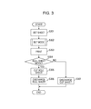
- Fig. 3 is a flow chart illustrating the overall operation of the printer according to the embodiment of the present invention.
- Fig. 4 is a flow chart illustrating a mode setting process in the printer according to the embodiment of the present invention.
- Figs. 5A and 5B schematically illustrate a mode determining process in the printer according to the embodiment of the present invention.
- FIG. 1A and 1B schematically illustrate a printer 200 according to this embodiment. Specifically, Fig. 1A illustrates a state where a roll sheet is set, whereas Fig. 1B illustrates a state where a cut sheet is set.
- reference numeral 100 denotes a recording head that ejects ink
- 101 denotes a carriage that carries the recording head 100 and that reciprocates perpendicularly to the plane of Figs. 1A and 1B
- 102 denotes a platen that supports a sheet.
- the printer 200 performs recording (printing) by ejecting ink from the recording head 100 onto the sheet supported by the platen 102 while reciprocating the carriage 101.
- reference numerals 103 and 104 denote sheet sensors serving as detectors that detect whether there is a sheet in a conveying path
- 105 denotes a pair of rollers (i.e., a pair of sheet conveying rollers) for nipping and conveying a sheet. At least one of the sheet conveying rollers 105 is movable away from the other roller.
- the lower roller of the sheet conveying rollers 105 is a conveying roller that is driven and rotated by a conveying motor 222. In a state where a sheet is nipped between the sheet conveying rollers 105, one of the conveying rollers actively rotates to convey the sheet.
- reference numeral 106 denotes a sheet cutter that cuts a sheet
- 107 denotes a roll-sheet conveying unit
- 108 denotes a cut-sheet guide that supports a cut sheet
- 109 denotes a roll sheet serving as a continuous recording medium
- 110 denotes a cut sheet.
- the roll-sheet conveying unit 107 serves as a first feeder (support unit) that rotatably supports the roll sheet 109 and feeds the roll sheet 109 to the conveying path.
- the cut-sheet guide 108 serves as a second feeder that feeds the cut sheet 110 to the conveying path.
- the roll-sheet conveying unit 107 performs a first operation for rotating a rolled section 109a of the roll sheet 109 in a direction for unwinding the roll sheet 109, and a second operation for rotating the rolled section 109a in a direction for rewinding the roll sheet 109 around the rolled section 109a.
- the roll-sheet conveying unit 107 has a spool 111 that is fitted to a core of the roll sheet 109 and a spool motor 221 (see Fig. 2 ) that rotates the spool 111.
- the rolled section 109a is rotated in the unwinding direction or the rewinding direction of the roll sheet 109.
- Figs. 1A and 1B when the spool 111 rotates counterclockwise (in the forward direction), the roll sheet 109 is unwound from the rolled section 109a so that the unwound roll sheet 109 is conveyed leftward from the right side in the drawing.
- the spool 111 rotates clockwise (in the reverse direction)
- the roll sheet 109 is rewound around the rolled section 109a.
- the roll sheet 109 conveyed by the roll-sheet conveying unit 107 or the cut sheet 110 placed on the cut-sheet guide 108 is guided to the conveying path (conveying section).
- the pair of sheet conveying rollers 105 starts rotating so as to convey the sheet leftward in the drawing.
- the pair of sheet conveying rollers 105 temporarily stops rotating, so that the sheet setting process is completed.
- the roll-sheet conveying unit 107 is a designated conveying unit for conveying the roll sheet 109.
- the pair of sheet conveying rollers 105 is a common conveying unit that conveys both the roll sheet 109 and the cut sheet 110 as recording media in a single conveying path.
- the pair of sheet conveying rollers 105 serving as a common conveying unit is disposed downstream of the roll-sheet conveying unit 107 in the sheet conveying direction. Moreover, in the conveying path, the second sheet sensor 103 serving as a detector is disposed downstream of the pair of sheet conveying rollers 105 in the sheet conveying direction.
- the printer 200 switches to a discharging process. Specifically, when in a roll-sheet mode, the roll sheet 109 is cut by the sheet cutter 106 upon completion of the printing performed on the roll sheet 109. Subsequently, the pair of sheet conveying rollers 105 rotates so as to convey the remaining roll sheet leftward, whereby the cut and printed roll sheet is pushed leftward to a discharge unit. Then, the remaining roll sheet is conveyed rightward by the pair of sheet conveying rollers 105, and the spool 111 rotates clockwise so as to rewind the remaining roll sheet.
- the pair of sheet conveying rollers 105 rotates upon completion of the printing performed on the cut sheet 110 so as to convey and discharge the printed cut sheet 110 leftward to the discharge unit.
- the sheet cutter 106 is not activated.
- Fig. 2 is a block diagram illustrating the configuration of the printer 200 according to the present embodiment.
- reference numeral 300 denotes a host computer
- 220 denotes a communication cable, such as a USB cable or a network cable.
- Print data is transmitted to the printer 200 from the host computer 300 via the communication cable 220.
- the printer 200 has a controller 210 serving as a control unit that includes a central processing unit (CPU) 201, a read-only memory (ROM) 202, a random access memory (RAM) 203, an interface (I/F) 204, a conveyance controller 205, and a print controller 206.
- the CPU 201 controls the overall operation of the printer 200.
- the ROM 202 contains a firmware program for controlling the printer 200 and a boot program for controlling the firmware program, and is used by the CPU 201.
- the RAM 203 serves as a work area for the CPU 201 and a temporary data storage area.
- the I/F 204 is connected to the host computer 300 and transmits image data.
- the conveyance controller 205 controls the spool motor 221 and the conveying motor 222, which drives the pair of sheet conveying rollers 105, via motor drivers 223 and 224.
- the print controller 206 controls the recording head 100 and the carriage 101 on the basis of the print data.
- a system bus 207 connects the CPU 201 to other components.
- Fig. 3 is a flow chart illustrating the operation of the printer 200 according to the present embodiment.
- the roll sheet 109 shown in Fig. 1A or the cut sheet 110 shown in Fig. 1B reaches a detecting position of the first sheet sensor 104, the pair of sheet conveying rollers 105 starts rotating so as to convey the sheet leftward. Subsequently, when the sheet is detected by the second sheet sensor 103, the pair of sheet conveying rollers 105 temporarily stops rotating, so that the sheet setting process is completed in step S301.
- the operation mode is automatically set by a mode setting unit.
- printing operation commences.
- step S304 it is determined in step S304 whether the set operation mode is the roll-sheet mode (first mode) or the cut-sheet mode (second mode). If it is determined that the set operation mode is the roll-sheet mode, a sheet cutting process is performed in step S305, and the roll sheet is discharged in step S306. On the other hand, if it is determined that the set operation mode is the cut-sheet mode, the cut sheet is discharged in step S307.
- the roll-sheet mode is an operation mode for performing printing on a roll sheet
- the cut-sheet mode is an operation mode for performing printing on a cut sheet.
- the sheet cutter 106 is activated after the printing operation so that the printed portion of the roll sheet is cut off therefrom. In the cut-sheet mode, the printed cut sheet is discharged without activating the sheet cutter 106.
- step S402 the roll-sheet conveying unit 107 (see Fig. 1A ) rotates the rolled section 109a clockwise in response to a command from the conveyance controller 205 (see Fig. 2 ) having received a command from the CPU 201, so that the roll sheet 109 is rewound around the rolled section 109a.
- the CPU 201 detects whether there is a sheet present by using the second sheet sensor 103 in step S403, and sets the operation mode based on the detection result. Specifically, if a sheet is detected by the second sheet sensor 103, the CPU 201 sets the operation mode to the cut-sheet mode in step S406, whereas if a sheet is not detected, the CPU 201 sets the operation mode to the roll-sheet mode in step S404. If the roll-sheet mode is set, the sheet setting process is performed again in step S405.
- step S401 shown in Fig. 4 may be omitted.
- rewinding the roll sheet 109 after moving the sheet conveying rollers 105 away from each other can prevent scraping of the sheet.
- step S301 in Fig. 3 the leading edge of a sheet 500 is located at a position detectable by the second sheet sensor 103.
- step S401 in Fig. 4 the upper pinch roller of the pair of sheet conveying rollers 105 is lifted away from the lower conveying roller, as shown in Fig. 5A .
- step S402 in Fig. 4 the roll-sheet rewinding process
- the leading edge of the sheet 500 moves (recedes) in accordance with the rewinding process of the roll sheet 109 to a position undetectable by the second sheet sensor 103, as shown in Fig. 5B . Consequently, when a sheet is not detected by the second sheet sensor 103, it is determined that the set sheet 500 is a roll sheet, and the roll-sheet mode is thus set.
- the controller 210 determines that the sheet 500 has moved from a predetermined position and detects the movement of the sheet 500.
- the controller 210 and the second sheet sensor 103 constitute a movement detecting unit. Therefore, in another exemplary embodiment, the second sheet sensor 103 that detects whether there is a sheet present may be replaced with a sensor that detects the movement of a sheet.
- the controller 210 has detected that the sheet 500 has moved in conjunction with the rewinding of the roll sheet.
- the controller 210 and the second sheet sensor 103 constitute a conjunctional-movement detecting unit. Therefore, in another exemplary embodiment, the second sheet sensor 103 may be replaced with a sensor that monitors the movement of the rolled section 109a and the sheet 500 so as to detect conjunctional movement of the two.
- the sheet 500 does not move even when the roll-sheet rewinding process (step S402 in Fig. 4 ) is performed. Therefore, if a sheet is detected again by the second sheet sensor 103, it is determined that the set sheet 500 is a cut sheet, and the cut-sheet mode is thus set.
- the roll-sheet conveying unit 107 shown in Figs. 1A and 1B may alternatively have a roller that rotates in contact with the roll sheet, such that by rotating this roller in the forward or reverse direction, the roll sheet can be rotated in the unwinding direction or the rewinding direction of the roll sheet.
Landscapes
- Life Sciences & Earth Sciences (AREA)
- Forests & Forestry (AREA)
- Engineering & Computer Science (AREA)
- Mechanical Engineering (AREA)
- Handling Of Sheets (AREA)
- Handling Of Continuous Sheets Of Paper (AREA)
Abstract

Description
- The present invention relates to printers that can perform recording on both roll sheets and cut sheets, and to conveying devices included in such printers.
- Printers that are capable of performing recording on both roll sheets and cut sheets are known. A printer of this type has two operation modes, which are a roll-sheet operation mode and a cut-sheet operation mode. Specifically, the printer has a roll-sheet mode for cutting and discharging a roll sheet upon completion of recording performed on the roll sheet and a cut-sheet mode for discharging a cut sheet upon completion of recording performed on the cut sheet. Furthermore, the printer has a mode setting unit for setting the operation mode to one of the two modes.
- However, the following problem occurs if the matching between the set mode and the actually set sheet is incorrect. Specifically, if a roll sheet is set when the operation mode is set to the cut-sheet mode, the trailing edge of the sheet cannot be detected during the discharging process, resulting in continuous feeding of the roll sheet. On the other hand, if a cut sheet is set when the operation mode is set to the roll-sheet mode, the cut sheet would be cut during the discharging process.
- Japanese Patent Laid-Open No.
2000-117691 - However, in the technology disclosed in Japanese Patent Laid-Open No.
2000-117691 - The present invention allows for automatic setting of an appropriate operation mode to avoid an incorrectly set operation mode.
- The present invention in its first aspect provides a conveying device as specified in claim 1.
- Claims 2 to 8 relate to embodiments and further developments of the conveying device as defined in claim 1.
- The present invention in its second aspect provides a printer as specified in claim 10.
- This printer comprises a conveying device of the present invention.
- According to the present invention, since an appropriate operation mode is automatically set, an incorrectly set operation mode can be avoided.
- Further features of the present invention will become apparent from the following description of exemplary embodiments with reference to the attached drawings.
-
Figs. 1A and 1B schematically illustrate a printer according to an embodiment of the present invention. -
Fig. 2 is a block diagram schematically illustrating the system configuration of the printer according to the embodiment of the present invention. -
Fig. 3 is a flow chart illustrating the overall operation of the printer according to the embodiment of the present invention. -
Fig. 4 is a flow chart illustrating a mode setting process in the printer according to the embodiment of the present invention. -
Figs. 5A and 5B schematically illustrate a mode determining process in the printer according to the embodiment of the present invention. - An embodiment of the present invention will be described below with reference to the drawings.
Figs. 1A and 1B schematically illustrate aprinter 200 according to this embodiment. Specifically,Fig. 1A illustrates a state where a roll sheet is set, whereasFig. 1B illustrates a state where a cut sheet is set. - In
Figs. 1A and 1B ,reference numeral 100 denotes a recording head that ejects ink, 101 denotes a carriage that carries therecording head 100 and that reciprocates perpendicularly to the plane ofFigs. 1A and 1B , and 102 denotes a platen that supports a sheet. Theprinter 200 performs recording (printing) by ejecting ink from therecording head 100 onto the sheet supported by theplaten 102 while reciprocating thecarriage 101. - In
Figs. 1A and 1B ,reference numerals sheet conveying rollers 105 is movable away from the other roller. The lower roller of thesheet conveying rollers 105 is a conveying roller that is driven and rotated by a conveyingmotor 222. In a state where a sheet is nipped between thesheet conveying rollers 105, one of the conveying rollers actively rotates to convey the sheet. - Furthermore, in
Figs. 1A and 1B ,reference numeral 106 denotes a sheet cutter that cuts a sheet, 107 denotes a roll-sheet conveying unit, 108 denotes a cut-sheet guide that supports a cut sheet, 109 denotes a roll sheet serving as a continuous recording medium, and 110 denotes a cut sheet. The roll-sheet conveying unit 107 serves as a first feeder (support unit) that rotatably supports theroll sheet 109 and feeds theroll sheet 109 to the conveying path. The cut-sheet guide 108 serves as a second feeder that feeds thecut sheet 110 to the conveying path. - The roll-
sheet conveying unit 107 performs a first operation for rotating a rolledsection 109a of theroll sheet 109 in a direction for unwinding theroll sheet 109, and a second operation for rotating the rolledsection 109a in a direction for rewinding theroll sheet 109 around the rolledsection 109a. Specifically, the roll-sheet conveying unit 107 has aspool 111 that is fitted to a core of theroll sheet 109 and a spool motor 221 (seeFig. 2 ) that rotates thespool 111. By using thespool motor 221 to rotate thespool 111 in the forward or reverse direction, the rolledsection 109a is rotated in the unwinding direction or the rewinding direction of theroll sheet 109. InFigs. 1A and 1B , when thespool 111 rotates counterclockwise (in the forward direction), theroll sheet 109 is unwound from the rolledsection 109a so that theunwound roll sheet 109 is conveyed leftward from the right side in the drawing. On the other hand, when thespool 111 rotates clockwise (in the reverse direction), theroll sheet 109 is rewound around the rolledsection 109a. - The
roll sheet 109 conveyed by the roll-sheet conveying unit 107 or thecut sheet 110 placed on the cut-sheet guide 108 is guided to the conveying path (conveying section). When the leading edge of theroll sheet 109 or thecut sheet 110 guided to the conveying path is detected by thefirst sheet sensor 104, the pair ofsheet conveying rollers 105 starts rotating so as to convey the sheet leftward in the drawing. Subsequently, when the sheet is detected by the second sheet sensor (detector) 103, the pair ofsheet conveying rollers 105 temporarily stops rotating, so that the sheet setting process is completed. - As described above, the roll-
sheet conveying unit 107 is a designated conveying unit for conveying theroll sheet 109. In contrast, the pair ofsheet conveying rollers 105 is a common conveying unit that conveys both theroll sheet 109 and thecut sheet 110 as recording media in a single conveying path. - The pair of
sheet conveying rollers 105 serving as a common conveying unit is disposed downstream of the roll-sheet conveying unit 107 in the sheet conveying direction. Moreover, in the conveying path, thesecond sheet sensor 103 serving as a detector is disposed downstream of the pair ofsheet conveying rollers 105 in the sheet conveying direction. - When printing performed on the
roll sheet 109 or thecut sheet 110 conveyed to a recording area of therecording head 100 in the above-described manner is completed, theprinter 200 switches to a discharging process. Specifically, when in a roll-sheet mode, theroll sheet 109 is cut by thesheet cutter 106 upon completion of the printing performed on theroll sheet 109. Subsequently, the pair ofsheet conveying rollers 105 rotates so as to convey the remaining roll sheet leftward, whereby the cut and printed roll sheet is pushed leftward to a discharge unit. Then, the remaining roll sheet is conveyed rightward by the pair ofsheet conveying rollers 105, and thespool 111 rotates clockwise so as to rewind the remaining roll sheet. On the other hand, when in a cut-sheet mode, the pair ofsheet conveying rollers 105 rotates upon completion of the printing performed on thecut sheet 110 so as to convey and discharge the printedcut sheet 110 leftward to the discharge unit. In this case, thesheet cutter 106 is not activated. -
Fig. 2 is a block diagram illustrating the configuration of theprinter 200 according to the present embodiment. InFig. 2 ,reference numeral 300 denotes a host computer, and 220 denotes a communication cable, such as a USB cable or a network cable. Print data is transmitted to theprinter 200 from thehost computer 300 via thecommunication cable 220. Theprinter 200 has acontroller 210 serving as a control unit that includes a central processing unit (CPU) 201, a read-only memory (ROM) 202, a random access memory (RAM) 203, an interface (I/F) 204, aconveyance controller 205, and aprint controller 206. TheCPU 201 controls the overall operation of theprinter 200. TheROM 202 contains a firmware program for controlling theprinter 200 and a boot program for controlling the firmware program, and is used by theCPU 201. TheRAM 203 serves as a work area for theCPU 201 and a temporary data storage area. The I/F 204 is connected to thehost computer 300 and transmits image data. Theconveyance controller 205 controls thespool motor 221 and the conveyingmotor 222, which drives the pair ofsheet conveying rollers 105, viamotor drivers print controller 206 controls therecording head 100 and thecarriage 101 on the basis of the print data. Asystem bus 207 connects theCPU 201 to other components. -
Fig. 3 is a flow chart illustrating the operation of theprinter 200 according to the present embodiment. When theroll sheet 109 shown inFig. 1A or thecut sheet 110 shown inFig. 1B reaches a detecting position of thefirst sheet sensor 104, the pair ofsheet conveying rollers 105 starts rotating so as to convey the sheet leftward. Subsequently, when the sheet is detected by thesecond sheet sensor 103, the pair ofsheet conveying rollers 105 temporarily stops rotating, so that the sheet setting process is completed in step S301. In step S302, the operation mode is automatically set by a mode setting unit. In step S303, printing operation commences. When the printing operation is completed, it is determined in step S304 whether the set operation mode is the roll-sheet mode (first mode) or the cut-sheet mode (second mode). If it is determined that the set operation mode is the roll-sheet mode, a sheet cutting process is performed in step S305, and the roll sheet is discharged in step S306. On the other hand, if it is determined that the set operation mode is the cut-sheet mode, the cut sheet is discharged in step S307. The roll-sheet mode is an operation mode for performing printing on a roll sheet, whereas the cut-sheet mode is an operation mode for performing printing on a cut sheet. In the roll-sheet mode, thesheet cutter 106 is activated after the printing operation so that the printed portion of the roll sheet is cut off therefrom. In the cut-sheet mode, the printed cut sheet is discharged without activating thesheet cutter 106. - The operation-mode setting procedure performed by the mode setting unit will now be described with reference to
Fig. 4 . When the sheet setting process is completed, the CPU 201 (seeFig. 2 ) moves one of the sheet conveying rollers 105 (seeFig. 1A ) away from the other roller in step S401. Subsequently, in step S402, the roll-sheet conveying unit 107 (seeFig. 1A ) rotates the rolledsection 109a clockwise in response to a command from the conveyance controller 205 (seeFig. 2 ) having received a command from theCPU 201, so that theroll sheet 109 is rewound around the rolledsection 109a. When the rewinding of theroll sheet 109 is completed, theCPU 201 detects whether there is a sheet present by using thesecond sheet sensor 103 in step S403, and sets the operation mode based on the detection result. Specifically, if a sheet is detected by thesecond sheet sensor 103, theCPU 201 sets the operation mode to the cut-sheet mode in step S406, whereas if a sheet is not detected, theCPU 201 sets the operation mode to the roll-sheet mode in step S404. If the roll-sheet mode is set, the sheet setting process is performed again in step S405. - It is also possible to rewind the
roll sheet 109 without moving thesheet conveying rollers 105 away from each other. In other words, step S401 shown inFig. 4 may be omitted. However, rewinding theroll sheet 109 after moving thesheet conveying rollers 105 away from each other can prevent scraping of the sheet. - The operation mode setting method will be further described with reference to
Figs. 5A and 5B . When the sheet setting process (step S301 inFig. 3 ) is completed as inFigs. 1A and 1B , the leading edge of asheet 500 is located at a position detectable by thesecond sheet sensor 103. Then, in step S401 inFig. 4 , the upper pinch roller of the pair ofsheet conveying rollers 105 is lifted away from the lower conveying roller, as shown inFig. 5A . When the roll-sheet rewinding process (step S402 inFig. 4 ) is performed in this state, if thesheet 500 is a roll sheet, thesheet 500 moves rightward in conjunction with the rewoundroll sheet 109. As a result, the leading edge of thesheet 500 moves (recedes) in accordance with the rewinding process of theroll sheet 109 to a position undetectable by thesecond sheet sensor 103, as shown inFig. 5B . Consequently, when a sheet is not detected by thesecond sheet sensor 103, it is determined that theset sheet 500 is a roll sheet, and the roll-sheet mode is thus set. - When the
second sheet sensor 103 switches from a sheet detectable state to a sheet undetectable state, thecontroller 210 determines that thesheet 500 has moved from a predetermined position and detects the movement of thesheet 500. Specifically, thecontroller 210 and thesecond sheet sensor 103 constitute a movement detecting unit. Therefore, in another exemplary embodiment, thesecond sheet sensor 103 that detects whether there is a sheet present may be replaced with a sensor that detects the movement of a sheet. - Alternatively, because the
sheet 500 has moved as a result of the roll-sheet rewinding process, this also implies that thecontroller 210 has detected that thesheet 500 has moved in conjunction with the rewinding of the roll sheet. Specifically, thecontroller 210 and thesecond sheet sensor 103 constitute a conjunctional-movement detecting unit. Therefore, in another exemplary embodiment, thesecond sheet sensor 103 may be replaced with a sensor that monitors the movement of the rolledsection 109a and thesheet 500 so as to detect conjunctional movement of the two. - On the other hand, if the
set sheet 500 is a cut sheet, thesheet 500 does not move even when the roll-sheet rewinding process (step S402 inFig. 4 ) is performed. Therefore, if a sheet is detected again by thesecond sheet sensor 103, it is determined that theset sheet 500 is a cut sheet, and the cut-sheet mode is thus set. - The roll-
sheet conveying unit 107 shown inFigs. 1A and 1B may alternatively have a roller that rotates in contact with the roll sheet, such that by rotating this roller in the forward or reverse direction, the roll sheet can be rotated in the unwinding direction or the rewinding direction of the roll sheet. - While the present invention has been described with reference to exemplary embodiments, it is to be understood that the invention is not limited to the disclosed exemplary embodiments. The scope of the following claims is to be accorded the broadest interpretation so as to encompass all such modifications and equivalent structures and functions.
Claims (10)
- A conveying device comprising:a first feeder (107) that rotatably supports a roll sheet (109) and feeds the roll sheet to a conveying path;a second feeder (108) that feeds a cut sheet (110) to the conveying path; anda controller (210) that determines whether a sheet fed to the conveying path is the roll sheet or the cut sheet based on a relationship between movement of the sheet fed to the conveying path and rotation of the roll sheet.
- The conveying device according to Claim 1, wherein the controller determines that the sheet fed to the conveying path is the roll sheet if the rotation and the movement occur in conjunction with each other when the roll sheet is rotated in a reverse direction of a feeding direction of the roll sheet, and wherein the controller determines, if the rotation and the movement do not occur in conjunction with each other, that the sheet fed to the conveying path is the cut sheet.
- The conveying device according to Claim 1, wherein the controller sets a mode for cutting the sheet fed to the conveying path when the controller determines that the sheet is the roll sheet and sets a mode for not cutting the sheet fed to the conveying path when the controller determines that the sheet is the cut sheet.
- The conveying device according to Claim 1, further comprising a sensor that detects the movement of the sheet in the conveying path,
wherein the controller determines that the sheet fed to the conveying path is the roll sheet if the sensor detects the movement of the sheet when the roll sheet is rotated in a winding direction in the first feeder. - The conveying device according to Claim 1, further comprising a pair of rollers (105) that nip and convey the sheet in the conveying path,
wherein the pair of rollers does not nip the sheet when the controller performs the determination process. - The conveying device according to Claim 1, further comprising a detector (103) that detects whether a sheet is present in the conveying path in which both the roll sheet and the cut sheet are conveyed, configured such that
the first feeder performs a first operation for rotating the roll sheet in an unwinding direction and a second operation for rotating the roll sheet in a rewinding direction; and
the controller sets a first mode for cutting the roll sheet or a second mode for discharging the cut sheet,
wherein, if the sheet is detected by the detector, the second operation is performed, and
wherein the controller sets the second mode if the sheet is detected again by the detector after the second operation or sets the first mode if the sheet is not detected by the detector after the second operation. - The conveying device according to Claim 6, wherein the first feeder rotates a spool (111) fitted in the roll sheet so as to rotate the roll sheet in the unwinding direction or the rewinding direction.
- The conveying device according to Claim 6, wherein the first feeder has a roller that rotates in contact with the roll sheet, and rotates the roller so as to rotate the roll sheet in the unwinding direction or the rewinding direction.
- The conveying device according to Claim 1, configured such that
the conveying path guides the roll sheet or the cut sheet (110) as a recording medium; and further comprising
mode setting means (210) configured to set at least one of a roll-sheet mode for cutting the recording medium and a cut-sheet mode for discharging the recording medium without cutting the recording medium; and
conjunctional-movement detecting means (103, 210) configured to detect whether the recording medium guided by the conveying path and the roll sheet supported by the first feeder move in conjunction with each other,
wherein the mode setting means sets the roll-sheet mode if the recording medium and the roll sheet move in conjunction with each other, and sets the cut-sheet mode if the recording medium and the roll sheet do not move in conjunction with each other. - A printer (200) that performs recording on a roll sheet (109) and a cut sheet (110), comprising:the conveying device according to any one of Claims 1 to 9; anda recording device that performs recording on a sheet conveyed by the conveying device,configured such thatthe controller sets a first mode for performing printing on the roll sheet or a second mode for performing printing on the cut sheet, andthe controller sets the second mode if the sheet fed to the conveying path is determined as the cut sheet and sets the first mode if the sheet fed to the conveying path is determined as the roll sheet.
Applications Claiming Priority (1)
| Application Number | Priority Date | Filing Date | Title |
|---|---|---|---|
| JP2010280375 | 2010-12-16 |
Publications (3)
| Publication Number | Publication Date |
|---|---|
| EP2465688A2 true EP2465688A2 (en) | 2012-06-20 |
| EP2465688A3 EP2465688A3 (en) | 2018-01-03 |
| EP2465688B1 EP2465688B1 (en) | 2019-05-22 |
Family
ID=45370371
Family Applications (1)
| Application Number | Title | Priority Date | Filing Date |
|---|---|---|---|
| EP11009609.6A Active EP2465688B1 (en) | 2010-12-16 | 2011-12-06 | Conveying device and printer |
Country Status (4)
| Country | Link |
|---|---|
| US (1) | US8845214B2 (en) |
| EP (1) | EP2465688B1 (en) |
| JP (1) | JP2012139998A (en) |
| KR (1) | KR20120067956A (en) |
Cited By (2)
| Publication number | Priority date | Publication date | Assignee | Title |
|---|---|---|---|---|
| CN104802536A (en) * | 2014-01-29 | 2015-07-29 | 东芝泰格有限公司 | Image forming device |
| EP3153321A3 (en) * | 2015-10-09 | 2017-04-26 | Canon Kabushiki Kaisha | Recording apparatus, method for controlling recording apparatus, and program |
Families Citing this family (2)
| Publication number | Priority date | Publication date | Assignee | Title |
|---|---|---|---|---|
| JP6115536B2 (en) * | 2014-09-25 | 2017-04-19 | コニカミノルタ株式会社 | Image forming apparatus |
| JP7840703B2 (en) * | 2022-01-28 | 2026-04-06 | キヤノン株式会社 | Recording device |
Citations (1)
| Publication number | Priority date | Publication date | Assignee | Title |
|---|---|---|---|---|
| JP2000117691A (en) | 1998-10-08 | 2000-04-25 | Seiko Epson Corp | Printer with cutter |
Family Cites Families (7)
| Publication number | Priority date | Publication date | Assignee | Title |
|---|---|---|---|---|
| JPH0739196B2 (en) * | 1988-06-10 | 1995-05-01 | 沖電気工業株式会社 | Printer paper feed control method |
| JPH06135075A (en) * | 1992-10-22 | 1994-05-17 | Tokyo Electric Co Ltd | Printer |
| JPH0731391U (en) * | 1993-11-19 | 1995-06-13 | 武藤工業株式会社 | Plotter for roll paper and cut paper |
| JPH09263015A (en) * | 1996-03-29 | 1997-10-07 | Copyer Co Ltd | Image forming device |
| JP2010069664A (en) * | 2008-09-17 | 2010-04-02 | Canon Inc | Recording device |
| JP2010241029A (en) * | 2009-04-08 | 2010-10-28 | Seiko Epson Corp | Liquid ejection device |
| JP5562182B2 (en) * | 2010-09-06 | 2014-07-30 | キヤノン株式会社 | Image recording apparatus and control method thereof |
-
2011
- 2011-12-06 EP EP11009609.6A patent/EP2465688B1/en active Active
- 2011-12-09 US US13/316,347 patent/US8845214B2/en active Active
- 2011-12-09 JP JP2011270018A patent/JP2012139998A/en active Pending
- 2011-12-15 KR KR1020110135459A patent/KR20120067956A/en not_active Ceased
Patent Citations (1)
| Publication number | Priority date | Publication date | Assignee | Title |
|---|---|---|---|---|
| JP2000117691A (en) | 1998-10-08 | 2000-04-25 | Seiko Epson Corp | Printer with cutter |
Cited By (2)
| Publication number | Priority date | Publication date | Assignee | Title |
|---|---|---|---|---|
| CN104802536A (en) * | 2014-01-29 | 2015-07-29 | 东芝泰格有限公司 | Image forming device |
| EP3153321A3 (en) * | 2015-10-09 | 2017-04-26 | Canon Kabushiki Kaisha | Recording apparatus, method for controlling recording apparatus, and program |
Also Published As
| Publication number | Publication date |
|---|---|
| US20120153000A1 (en) | 2012-06-21 |
| JP2012139998A (en) | 2012-07-26 |
| KR20120067956A (en) | 2012-06-26 |
| EP2465688A3 (en) | 2018-01-03 |
| US8845214B2 (en) | 2014-09-30 |
| EP2465688B1 (en) | 2019-05-22 |
Similar Documents
| Publication | Publication Date | Title |
|---|---|---|
| US8714541B2 (en) | Image recording apparatus and control method thereof | |
| US12090753B2 (en) | Medium cassette and image recording apparatus | |
| US11667138B2 (en) | Printing apparatus, control method, and non-transitory computer-readable storage medium | |
| US12157299B2 (en) | Printing apparatus, printing method, and non-transitory computer-readable storage medium | |
| JP5371283B2 (en) | Recording device | |
| US10239332B2 (en) | Printer, and printer control method | |
| KR20130020620A (en) | Printing apparatus and method for conveying printing medium | |
| CN110126460B (en) | Printing apparatus | |
| EP2465688B1 (en) | Conveying device and printer | |
| JP7328782B2 (en) | Recording device and control method | |
| US11838463B2 (en) | Printing apparatus and method for controlling printing apparatus | |
| JP5672122B2 (en) | Image forming apparatus and program | |
| US9162490B2 (en) | Sheet supply apparatus and printing apparatus | |
| US11787654B2 (en) | Sheet feeding apparatus and printing apparatus | |
| JP2006289887A (en) | Printer recording paper loading method | |
| JP5451024B2 (en) | Conveying device and recording apparatus provided with the device | |
| US12589602B2 (en) | Printing apparatus including processing member for processing a print medium | |
| US20110215130A1 (en) | Sheet handling apparatus and sheet collecting method | |
| US8651478B2 (en) | Sheet conveying device and recording apparatus | |
| JP5095651B2 (en) | Printing device | |
| JP3466820B2 (en) | Recording medium transport device | |
| JP5279391B2 (en) | Sheet conveying apparatus and image forming apparatus | |
| JP2014100818A (en) | Image formation device, front end alignment method and front end alignment program | |
| JP2009102120A (en) | Printer device | |
| JPS62216776A (en) | Printing processing system for printing device |
Legal Events
| Date | Code | Title | Description |
|---|---|---|---|
| PUAI | Public reference made under article 153(3) epc to a published international application that has entered the european phase |
Free format text: ORIGINAL CODE: 0009012 |
|
| AK | Designated contracting states |
Kind code of ref document: A2 Designated state(s): AL AT BE BG CH CY CZ DE DK EE ES FI FR GB GR HR HU IE IS IT LI LT LU LV MC MK MT NL NO PL PT RO RS SE SI SK SM TR |
|
| AX | Request for extension of the european patent |
Extension state: BA ME |
|
| PUAL | Search report despatched |
Free format text: ORIGINAL CODE: 0009013 |
|
| AK | Designated contracting states |
Kind code of ref document: A3 Designated state(s): AL AT BE BG CH CY CZ DE DK EE ES FI FR GB GR HR HU IE IS IT LI LT LU LV MC MK MT NL NO PL PT RO RS SE SI SK SM TR |
|
| AX | Request for extension of the european patent |
Extension state: BA ME |
|
| RIC1 | Information provided on ipc code assigned before grant |
Ipc: B41J 11/00 20060101AFI20171124BHEP Ipc: B41J 11/48 20060101ALI20171124BHEP |
|
| STAA | Information on the status of an ep patent application or granted ep patent |
Free format text: STATUS: REQUEST FOR EXAMINATION WAS MADE |
|
| 17P | Request for examination filed |
Effective date: 20180703 |
|
| RBV | Designated contracting states (corrected) |
Designated state(s): AL AT BE BG CH CY CZ DE DK EE ES FI FR GB GR HR HU IE IS IT LI LT LU LV MC MK MT NL NO PL PT RO RS SE SI SK SM TR |
|
| GRAP | Despatch of communication of intention to grant a patent |
Free format text: ORIGINAL CODE: EPIDOSNIGR1 |
|
| STAA | Information on the status of an ep patent application or granted ep patent |
Free format text: STATUS: GRANT OF PATENT IS INTENDED |
|
| INTG | Intention to grant announced |
Effective date: 20181213 |
|
| GRAS | Grant fee paid |
Free format text: ORIGINAL CODE: EPIDOSNIGR3 |
|
| GRAA | (expected) grant |
Free format text: ORIGINAL CODE: 0009210 |
|
| STAA | Information on the status of an ep patent application or granted ep patent |
Free format text: STATUS: THE PATENT HAS BEEN GRANTED |
|
| AK | Designated contracting states |
Kind code of ref document: B1 Designated state(s): AL AT BE BG CH CY CZ DE DK EE ES FI FR GB GR HR HU IE IS IT LI LT LU LV MC MK MT NL NO PL PT RO RS SE SI SK SM TR |
|
| REG | Reference to a national code |
Ref country code: GB Ref legal event code: FG4D |
|
| REG | Reference to a national code |
Ref country code: CH Ref legal event code: EP |
|
| REG | Reference to a national code |
Ref country code: IE Ref legal event code: FG4D |
|
| REG | Reference to a national code |
Ref country code: DE Ref legal event code: R096 Ref document number: 602011059113 Country of ref document: DE |
|
| REG | Reference to a national code |
Ref country code: AT Ref legal event code: REF Ref document number: 1135622 Country of ref document: AT Kind code of ref document: T Effective date: 20190615 |
|
| REG | Reference to a national code |
Ref country code: NL Ref legal event code: MP Effective date: 20190522 |
|
| REG | Reference to a national code |
Ref country code: LT Ref legal event code: MG4D |
|
| PG25 | Lapsed in a contracting state [announced via postgrant information from national office to epo] |
Ref country code: SE Free format text: LAPSE BECAUSE OF FAILURE TO SUBMIT A TRANSLATION OF THE DESCRIPTION OR TO PAY THE FEE WITHIN THE PRESCRIBED TIME-LIMIT Effective date: 20190522 Ref country code: NL Free format text: LAPSE BECAUSE OF FAILURE TO SUBMIT A TRANSLATION OF THE DESCRIPTION OR TO PAY THE FEE WITHIN THE PRESCRIBED TIME-LIMIT Effective date: 20190522 Ref country code: ES Free format text: LAPSE BECAUSE OF FAILURE TO SUBMIT A TRANSLATION OF THE DESCRIPTION OR TO PAY THE FEE WITHIN THE PRESCRIBED TIME-LIMIT Effective date: 20190522 Ref country code: LT Free format text: LAPSE BECAUSE OF FAILURE TO SUBMIT A TRANSLATION OF THE DESCRIPTION OR TO PAY THE FEE WITHIN THE PRESCRIBED TIME-LIMIT Effective date: 20190522 Ref country code: FI Free format text: LAPSE BECAUSE OF FAILURE TO SUBMIT A TRANSLATION OF THE DESCRIPTION OR TO PAY THE FEE WITHIN THE PRESCRIBED TIME-LIMIT Effective date: 20190522 Ref country code: AL Free format text: LAPSE BECAUSE OF FAILURE TO SUBMIT A TRANSLATION OF THE DESCRIPTION OR TO PAY THE FEE WITHIN THE PRESCRIBED TIME-LIMIT Effective date: 20190522 Ref country code: PT Free format text: LAPSE BECAUSE OF FAILURE TO SUBMIT A TRANSLATION OF THE DESCRIPTION OR TO PAY THE FEE WITHIN THE PRESCRIBED TIME-LIMIT Effective date: 20190922 Ref country code: HR Free format text: LAPSE BECAUSE OF FAILURE TO SUBMIT A TRANSLATION OF THE DESCRIPTION OR TO PAY THE FEE WITHIN THE PRESCRIBED TIME-LIMIT Effective date: 20190522 Ref country code: NO Free format text: LAPSE BECAUSE OF FAILURE TO SUBMIT A TRANSLATION OF THE DESCRIPTION OR TO PAY THE FEE WITHIN THE PRESCRIBED TIME-LIMIT Effective date: 20190822 |
|
| PG25 | Lapsed in a contracting state [announced via postgrant information from national office to epo] |
Ref country code: GR Free format text: LAPSE BECAUSE OF FAILURE TO SUBMIT A TRANSLATION OF THE DESCRIPTION OR TO PAY THE FEE WITHIN THE PRESCRIBED TIME-LIMIT Effective date: 20190823 Ref country code: LV Free format text: LAPSE BECAUSE OF FAILURE TO SUBMIT A TRANSLATION OF THE DESCRIPTION OR TO PAY THE FEE WITHIN THE PRESCRIBED TIME-LIMIT Effective date: 20190522 Ref country code: BG Free format text: LAPSE BECAUSE OF FAILURE TO SUBMIT A TRANSLATION OF THE DESCRIPTION OR TO PAY THE FEE WITHIN THE PRESCRIBED TIME-LIMIT Effective date: 20190822 Ref country code: RS Free format text: LAPSE BECAUSE OF FAILURE TO SUBMIT A TRANSLATION OF THE DESCRIPTION OR TO PAY THE FEE WITHIN THE PRESCRIBED TIME-LIMIT Effective date: 20190522 |
|
| REG | Reference to a national code |
Ref country code: AT Ref legal event code: MK05 Ref document number: 1135622 Country of ref document: AT Kind code of ref document: T Effective date: 20190522 |
|
| PG25 | Lapsed in a contracting state [announced via postgrant information from national office to epo] |
Ref country code: DK Free format text: LAPSE BECAUSE OF FAILURE TO SUBMIT A TRANSLATION OF THE DESCRIPTION OR TO PAY THE FEE WITHIN THE PRESCRIBED TIME-LIMIT Effective date: 20190522 Ref country code: AT Free format text: LAPSE BECAUSE OF FAILURE TO SUBMIT A TRANSLATION OF THE DESCRIPTION OR TO PAY THE FEE WITHIN THE PRESCRIBED TIME-LIMIT Effective date: 20190522 Ref country code: EE Free format text: LAPSE BECAUSE OF FAILURE TO SUBMIT A TRANSLATION OF THE DESCRIPTION OR TO PAY THE FEE WITHIN THE PRESCRIBED TIME-LIMIT Effective date: 20190522 Ref country code: RO Free format text: LAPSE BECAUSE OF FAILURE TO SUBMIT A TRANSLATION OF THE DESCRIPTION OR TO PAY THE FEE WITHIN THE PRESCRIBED TIME-LIMIT Effective date: 20190522 Ref country code: CZ Free format text: LAPSE BECAUSE OF FAILURE TO SUBMIT A TRANSLATION OF THE DESCRIPTION OR TO PAY THE FEE WITHIN THE PRESCRIBED TIME-LIMIT Effective date: 20190522 Ref country code: SK Free format text: LAPSE BECAUSE OF FAILURE TO SUBMIT A TRANSLATION OF THE DESCRIPTION OR TO PAY THE FEE WITHIN THE PRESCRIBED TIME-LIMIT Effective date: 20190522 |
|
| REG | Reference to a national code |
Ref country code: DE Ref legal event code: R097 Ref document number: 602011059113 Country of ref document: DE |
|
| PG25 | Lapsed in a contracting state [announced via postgrant information from national office to epo] |
Ref country code: SM Free format text: LAPSE BECAUSE OF FAILURE TO SUBMIT A TRANSLATION OF THE DESCRIPTION OR TO PAY THE FEE WITHIN THE PRESCRIBED TIME-LIMIT Effective date: 20190522 Ref country code: IT Free format text: LAPSE BECAUSE OF FAILURE TO SUBMIT A TRANSLATION OF THE DESCRIPTION OR TO PAY THE FEE WITHIN THE PRESCRIBED TIME-LIMIT Effective date: 20190522 |
|
| PLBE | No opposition filed within time limit |
Free format text: ORIGINAL CODE: 0009261 |
|
| STAA | Information on the status of an ep patent application or granted ep patent |
Free format text: STATUS: NO OPPOSITION FILED WITHIN TIME LIMIT |
|
| PG25 | Lapsed in a contracting state [announced via postgrant information from national office to epo] |
Ref country code: TR Free format text: LAPSE BECAUSE OF FAILURE TO SUBMIT A TRANSLATION OF THE DESCRIPTION OR TO PAY THE FEE WITHIN THE PRESCRIBED TIME-LIMIT Effective date: 20190522 |
|
| 26N | No opposition filed |
Effective date: 20200225 |
|
| PG25 | Lapsed in a contracting state [announced via postgrant information from national office to epo] |
Ref country code: PL Free format text: LAPSE BECAUSE OF FAILURE TO SUBMIT A TRANSLATION OF THE DESCRIPTION OR TO PAY THE FEE WITHIN THE PRESCRIBED TIME-LIMIT Effective date: 20190522 |
|
| PG25 | Lapsed in a contracting state [announced via postgrant information from national office to epo] |
Ref country code: SI Free format text: LAPSE BECAUSE OF FAILURE TO SUBMIT A TRANSLATION OF THE DESCRIPTION OR TO PAY THE FEE WITHIN THE PRESCRIBED TIME-LIMIT Effective date: 20190522 |
|
| REG | Reference to a national code |
Ref country code: CH Ref legal event code: PL |
|
| REG | Reference to a national code |
Ref country code: BE Ref legal event code: MM Effective date: 20191231 |
|
| PG25 | Lapsed in a contracting state [announced via postgrant information from national office to epo] |
Ref country code: MC Free format text: LAPSE BECAUSE OF FAILURE TO SUBMIT A TRANSLATION OF THE DESCRIPTION OR TO PAY THE FEE WITHIN THE PRESCRIBED TIME-LIMIT Effective date: 20190522 |
|
| GBPC | Gb: european patent ceased through non-payment of renewal fee |
Effective date: 20191206 |
|
| PG25 | Lapsed in a contracting state [announced via postgrant information from national office to epo] |
Ref country code: GB Free format text: LAPSE BECAUSE OF NON-PAYMENT OF DUE FEES Effective date: 20191206 Ref country code: IE Free format text: LAPSE BECAUSE OF NON-PAYMENT OF DUE FEES Effective date: 20191206 Ref country code: FR Free format text: LAPSE BECAUSE OF NON-PAYMENT OF DUE FEES Effective date: 20191231 Ref country code: LU Free format text: LAPSE BECAUSE OF NON-PAYMENT OF DUE FEES Effective date: 20191206 |
|
| PG25 | Lapsed in a contracting state [announced via postgrant information from national office to epo] |
Ref country code: BE Free format text: LAPSE BECAUSE OF NON-PAYMENT OF DUE FEES Effective date: 20191231 Ref country code: LI Free format text: LAPSE BECAUSE OF NON-PAYMENT OF DUE FEES Effective date: 20191231 Ref country code: CH Free format text: LAPSE BECAUSE OF NON-PAYMENT OF DUE FEES Effective date: 20191231 |
|
| PG25 | Lapsed in a contracting state [announced via postgrant information from national office to epo] |
Ref country code: CY Free format text: LAPSE BECAUSE OF FAILURE TO SUBMIT A TRANSLATION OF THE DESCRIPTION OR TO PAY THE FEE WITHIN THE PRESCRIBED TIME-LIMIT Effective date: 20190522 |
|
| PG25 | Lapsed in a contracting state [announced via postgrant information from national office to epo] |
Ref country code: IS Free format text: LAPSE BECAUSE OF FAILURE TO SUBMIT A TRANSLATION OF THE DESCRIPTION OR TO PAY THE FEE WITHIN THE PRESCRIBED TIME-LIMIT Effective date: 20190922 |
|
| PG25 | Lapsed in a contracting state [announced via postgrant information from national office to epo] |
Ref country code: MT Free format text: LAPSE BECAUSE OF FAILURE TO SUBMIT A TRANSLATION OF THE DESCRIPTION OR TO PAY THE FEE WITHIN THE PRESCRIBED TIME-LIMIT Effective date: 20190522 Ref country code: HU Free format text: LAPSE BECAUSE OF FAILURE TO SUBMIT A TRANSLATION OF THE DESCRIPTION OR TO PAY THE FEE WITHIN THE PRESCRIBED TIME-LIMIT; INVALID AB INITIO Effective date: 20111206 |
|
| PG25 | Lapsed in a contracting state [announced via postgrant information from national office to epo] |
Ref country code: MK Free format text: LAPSE BECAUSE OF FAILURE TO SUBMIT A TRANSLATION OF THE DESCRIPTION OR TO PAY THE FEE WITHIN THE PRESCRIBED TIME-LIMIT Effective date: 20190522 |
|
| PGFP | Annual fee paid to national office [announced via postgrant information from national office to epo] |
Ref country code: DE Payment date: 20251126 Year of fee payment: 15 |