EP2465166B1 - Electrical hinge connector - Google Patents
Electrical hinge connector Download PDFInfo
- Publication number
- EP2465166B1 EP2465166B1 EP10747063.5A EP10747063A EP2465166B1 EP 2465166 B1 EP2465166 B1 EP 2465166B1 EP 10747063 A EP10747063 A EP 10747063A EP 2465166 B1 EP2465166 B1 EP 2465166B1
- Authority
- EP
- European Patent Office
- Prior art keywords
- hinge
- unit
- protrusion
- housing
- receptacle
- Prior art date
- Legal status (The legal status is an assumption and is not a legal conclusion. Google has not performed a legal analysis and makes no representation as to the accuracy of the status listed.)
- Active
Links
Images


Classifications
-
- H—ELECTRICITY
- H01—ELECTRIC ELEMENTS
- H01R—ELECTRICALLY-CONDUCTIVE CONNECTIONS; STRUCTURAL ASSOCIATIONS OF A PLURALITY OF MUTUALLY-INSULATED ELECTRICAL CONNECTING ELEMENTS; COUPLING DEVICES; CURRENT COLLECTORS
- H01R35/00—Flexible or turnable line connectors, i.e. the rotation angle being limited
- H01R35/04—Turnable line connectors with limited rotation angle with frictional contact members
-
- H—ELECTRICITY
- H01—ELECTRIC ELEMENTS
- H01R—ELECTRICALLY-CONDUCTIVE CONNECTIONS; STRUCTURAL ASSOCIATIONS OF A PLURALITY OF MUTUALLY-INSULATED ELECTRICAL CONNECTING ELEMENTS; COUPLING DEVICES; CURRENT COLLECTORS
- H01R13/00—Details of coupling devices of the kinds covered by groups H01R12/70 or H01R24/00 - H01R33/00
- H01R13/02—Contact members
- H01R13/04—Pins or blades for co-operation with sockets
-
- H—ELECTRICITY
- H01—ELECTRIC ELEMENTS
- H01R—ELECTRICALLY-CONDUCTIVE CONNECTIONS; STRUCTURAL ASSOCIATIONS OF A PLURALITY OF MUTUALLY-INSULATED ELECTRICAL CONNECTING ELEMENTS; COUPLING DEVICES; CURRENT COLLECTORS
- H01R13/00—Details of coupling devices of the kinds covered by groups H01R12/70 or H01R24/00 - H01R33/00
- H01R13/02—Contact members
- H01R13/10—Sockets for co-operation with pins or blades
- H01R13/11—Resilient sockets
- H01R13/111—Resilient sockets co-operating with pins having a circular transverse section
-
- H—ELECTRICITY
- H01—ELECTRIC ELEMENTS
- H01R—ELECTRICALLY-CONDUCTIVE CONNECTIONS; STRUCTURAL ASSOCIATIONS OF A PLURALITY OF MUTUALLY-INSULATED ELECTRICAL CONNECTING ELEMENTS; COUPLING DEVICES; CURRENT COLLECTORS
- H01R13/00—Details of coupling devices of the kinds covered by groups H01R12/70 or H01R24/00 - H01R33/00
- H01R13/02—Contact members
- H01R13/15—Pins, blades or sockets having separate spring member for producing or increasing contact pressure
- H01R13/187—Pins, blades or sockets having separate spring member for producing or increasing contact pressure with spring member in the socket
-
- H—ELECTRICITY
- H01—ELECTRIC ELEMENTS
- H01R—ELECTRICALLY-CONDUCTIVE CONNECTIONS; STRUCTURAL ASSOCIATIONS OF A PLURALITY OF MUTUALLY-INSULATED ELECTRICAL CONNECTING ELEMENTS; COUPLING DEVICES; CURRENT COLLECTORS
- H01R13/00—Details of coupling devices of the kinds covered by groups H01R12/70 or H01R24/00 - H01R33/00
- H01R13/02—Contact members
- H01R13/20—Pins, blades, or sockets shaped, or provided with separate member, to retain co-operating parts together
-
- H—ELECTRICITY
- H01—ELECTRIC ELEMENTS
- H01R—ELECTRICALLY-CONDUCTIVE CONNECTIONS; STRUCTURAL ASSOCIATIONS OF A PLURALITY OF MUTUALLY-INSULATED ELECTRICAL CONNECTING ELEMENTS; COUPLING DEVICES; CURRENT COLLECTORS
- H01R25/00—Coupling parts adapted for simultaneous co-operation with two or more identical counterparts, e.g. for distributing energy to two or more circuits
- H01R25/14—Rails or bus-bars constructed so that the counterparts can be connected thereto at any point along their length
- H01R25/145—Details, e.g. end pieces or joints
-
- E—FIXED CONSTRUCTIONS
- E05—LOCKS; KEYS; WINDOW OR DOOR FITTINGS; SAFES
- E05D—HINGES OR SUSPENSION DEVICES FOR DOORS, WINDOWS OR WINGS
- E05D11/00—Additional features or accessories of hinges
- E05D11/0081—Additional features or accessories of hinges for transmitting energy, e.g. electrical cable routing
-
- E—FIXED CONSTRUCTIONS
- E05—LOCKS; KEYS; WINDOW OR DOOR FITTINGS; SAFES
- E05Y—INDEXING SCHEME ASSOCIATED WITH SUBCLASSES E05D AND E05F, RELATING TO CONSTRUCTION ELEMENTS, ELECTRIC CONTROL, POWER SUPPLY, POWER SIGNAL OR TRANSMISSION, USER INTERFACES, MOUNTING OR COUPLING, DETAILS, ACCESSORIES, AUXILIARY OPERATIONS NOT OTHERWISE PROVIDED FOR, APPLICATION THEREOF
- E05Y2900/00—Application of doors, windows, wings or fittings thereof
- E05Y2900/10—Application of doors, windows, wings or fittings thereof for buildings or parts thereof
- E05Y2900/13—Type of wing
- E05Y2900/132—Doors
-
- H—ELECTRICITY
- H02—GENERATION; CONVERSION OR DISTRIBUTION OF ELECTRIC POWER
- H02G—INSTALLATION OF ELECTRIC CABLES OR LINES, OR OF COMBINED OPTICAL AND ELECTRIC CABLES OR LINES
- H02G3/00—Installations of electric cables or lines or protective tubing therefor in or on buildings, equivalent structures or vehicles
- H02G3/02—Details
- H02G3/08—Distribution boxes; Connection or junction boxes
- H02G3/16—Distribution boxes; Connection or junction boxes structurally associated with support for line-connecting terminals within the box
Definitions
- the present invention relates to hinges that provide an electrical connection, in particular for use in aircraft electrical power systems.
- the invention further relates to electrical power distribution systems for aircraft.
- DE 10101635 C1 discloses an electrical connector for cable sections comprising a hinge.
- US-A-3860312 relates to a hinge generally corresponding to the preamble of claim 1 herein.
- the present invention provides a hinge for an aircraft power distribution system unit, the unit having a housing comprising first and second housing parts, the hinge being according to claim 1 herein.
- the present invention overcomes the problems associated with cable connections, because the hinge allows easy rotation of the door of the unit, requiring a low force to open and/or close the door of the unit, whilst providing an electrical connection to transmit power to the components mounted on the door within the unit. Thus, no wires are needed to transmit current from the main body of the unit to the door-mounted components. A reduction in the overall volume and weight of the aircraft power distribution system unit is made possible by the invention.
- the second hinge member can be removably engagable in a cavity of the first hinge member, whereby the door of the unit can be easily plugged in and removed from the unit, without power cables restricting the motion of the door.
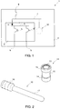
- a unit 1 of an aircraft electrical power distribution system is shown in Fig. 1 comprising a first housing part 3 and a second housing part 2.
- the second housing part 2 comprises a door rotatably connected via a hinge 4 to the first housing part 3, the first housing part comprising a main body of the unit 1.
- Electrical current enters the unit 1 via a power input 8, which provides power to an electrical bus 7 for distributing current to electrical loads 12 provided within the unit. Power is also transmitted from the input 8 to an electrical bus 6 that is mounted on the door 2 of the unit.
- the bus 6 on the door 2 is connected to the power input 8 via the bus 7 in the unit.
- the hinge 4 which connects the door 2 to the main body 3 of the unit 1 comprises electrically conductive material, whereby current can be conducted to the electrical bus 6.
- one or more electrical devices 5 are mounted on the door 2, preferably on the interior side of the door, and draw power from the bus 6, the devices being connected to corresponding power outputs 9. Where cable is used for the power outputs 9, this can be achieved using thinner, more flexible wires than those needed for the power input. Alternatively, the power output could be transmitted across a second hinge not shown in Fig. 1 .
- Fig. 2 shows two components of the hinge 4 comprising a first hinge member and a second hinge member 10, respectively comprising a receptacle 11 and a protrusion 17 for rotatable engagement in the receptacle.
- the receptacle 11 comprises a hyperboloid socket having a circular cross-section and including a cylindrical cavity 13 for receiving the protrusion 17, the end portions 14 of the receptacle 11 having a greater thickness and hence an enhanced strength compared to a central part 15 of the receptacle.
- the second hinge member 10 can connect to the receptacle with a push-fit mechanism.
- the internal structure of the hyperboloid socket 11 (not shown) includes a series of wires extending along the periphery of the cylindrical cavity 13 between the end portions 14, the end portions being twisted with respect to one another about a longitudinal axis of the socket, whereby the wires form a constriction towards the middle of the socket.
- the protrusion 17 of the second hinge member is cylindrical and adapted for mating insertion in the cylindrical cavity 13 of the receptacle, the longitudinal axis of the protrusion 17 coinciding with the axis of rotation of the hinge.
- the cylindrical surface of the protrusion 17 and the internal structure of the cavity 13 provide a reliable surface contact over a large area between the first and second hinge members thereby providing a good electrical connection between the hinge members capable of carrying the high currents required by aircraft power distribution systems. Further, the internal constriction of the socket facilitates the fixture of the protrusion within the socket.
- the second hinge member 10 opposed to the protrusion the second hinge member comprises a root portion 16 for connection to a busbar 18 shown in Fig. 4 , which supplies power to the door-mounted electrical devices 5.
- Both the first and second hinge members are made from electrically conductive materials, such as metals.
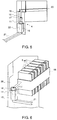
- the receptacle 11 of the hinge is connected to the housing by means of a mount 19 and a conductor 21 feeds current to the receptacle 11 from the bus 7.
- the electrical connection between the conductor bar 21 and the receptacle can be provided by means of a subsidiary connector (not shown in the drawings), which can extend through the mount 19.
- the mount 19 itself preferably comprises an electrically insulating material, which advantageously insulates the unit housing from the electrical current.
- Fig. 4 shows a busbar 18 which can be mounted on the door 2 of the unit and has the second hinge member 10 formed integrally therewith.
- the second hinge member is manufactured separately to the busbar 18 and is connected thereto by means of an electrically conductive joint.
- the busbar 18 supplies power to the electrical devices 5 and ensures that the electrical devices 5 are firmly held in place on the inside of the door.
- the hinge 4 is shown in a partially assembled or exploded view.
- the assembly of the hinge involves disposing the mount 19 on the main body of the unit 1.
- the receptacle 11 is inserted into a channel 22 in the mount 19 and the protrusion 17 of the second hinge member 10 is inserted into the cylindrical cavity 13 of the receptacle 11.
- the order in which these steps are carried out can be varied.
- Fig. 6 shows the hinge assembled, including a plurality of electrical devices 5 mounted underneath the busbar 18.
- the electrical devices 5 may comprise circuit breakers.
- the busbar 18 provides the input current to the circuit breakers 5, the output current from the circuit breakers 5 being significantly lower.
- the output current can be carried by thin, flexible wires, which can be accommodated in the unit and do not offer an excessive resistance to the opening and closing of the door 2.
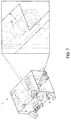
- Figs 7 and 8 show an assembled unit 1 of an aircraft power distribution system.
- First and second busbars 18 are provided on the interior side of the door, connected respectively to first and second hinges 4.
- First and second conductors 21 feed current respectively to the first and second hinges 4.
- Fig 7 the unit is shown in the closed position, while in Fig. 8 , the door of the unit is open to allow access to the components within.
- the hinge 4 allows for 120 degrees of door rotation, which is typically required for maintenance access.
- each hinge is capable of carrying 200A of current, allowing for 400A to be conducted across a pair of hinges.
- the example shown is a DC system, although the hinge can also be used in a system that runs on AC power.
- the power output is not shown in Figs 7 and 8 , but again can comprise wires or an output hinge.
- the size and quantity of the hinges can be varied depending on the specific mechanical and electrical design considerations at hand.
- the first and second hinge members can be mounted in reverse to the way shown in the Figures.
- the receptacle 11 can be mounted on the door 2 and the protrusion 17 on the main body 3 of the unit 1.
- the mount 19 is then provided on the door 2 for receiving the receptacle 11.
- the first and second hinge members can be manufactured by moulding from plastics materials.
Landscapes
- Patch Boards (AREA)
- Pivots And Pivotal Connections (AREA)
- Connector Housings Or Holding Contact Members (AREA)
- Casings For Electric Apparatus (AREA)
Description
- The present invention relates to hinges that provide an electrical connection, in particular for use in aircraft electrical power systems. The invention further relates to electrical power distribution systems for aircraft.
- The factors governing the design of modem power distribution systems which are installed in aircraft include cost, weight and volume. To drive down the overall package size, design measures are taken which utilize every available surface and space. However general operation and maintenance access is required over the life of the part and therefore components are often mounted on a hinged door on the unit. For primary power distribution, the components mounted on the door can require current feeds up to and in excess of 500A. Such large currents require cable feeds which are bulky, heavy and inherently inflexible. As an example, some cables need to be as thick as 15mm in diameter in order to carry the required current. As a result a great deal of space is required to accommodate the excess cable which brings with it additional weight, greater opening and closing forces to operate the door, and largely unpredictable wear and tear of the cable strands which are forced to act in a manner in which they are not mechanically designed to operate.
- One solution that has been proposed to overcome the problem of the amount of volume required is to allocate space in the unit to accommodate the excess cable. This however does not reduce the resistance to flex in the cable. An additional solution in the prior art has been to transmit the power across the door hinge by multiple cables in a bundle. This enables increased flexibility and therefore reduces the force required to open and close the door, however using multiple 'thinner' cables increases weight through the increased cross-sectional area of insulation and bundle retention. This also carries with it the risk of undetected faults if a wire breaks while others are connected in parallel.
-
DE 10101635 C1 discloses an electrical connector for cable sections comprising a hinge. -
US-A-3860312 relates to a hinge generally corresponding to the preamble ofclaim 1 herein. - The present invention provides a hinge for an aircraft power distribution system unit, the unit having a housing comprising first and second housing parts, the hinge being according to claim 1 herein.
- Advantageously, the present invention overcomes the problems associated with cable connections, because the hinge allows easy rotation of the door of the unit, requiring a low force to open and/or close the door of the unit, whilst providing an electrical connection to transmit power to the components mounted on the door within the unit. Thus, no wires are needed to transmit current from the main body of the unit to the door-mounted components. A reduction in the overall volume and weight of the aircraft power distribution system unit is made possible by the invention.
- The second hinge member can be removably engagable in a cavity of the first hinge member, whereby the door of the unit can be easily plugged in and removed from the unit, without power cables restricting the motion of the door.
- There follows a detailed description of embodiments of the invention by way of example only with reference to the accompanying drawings, in which:
-
Fig. 1 shows schematically a unit of an aircraft power distribution system according to the invention; -
Fig. 2 shows first and second hinge members according to the invention; -
Fig. 3 is a perspective view of a part of the hinge according to the invention; -
Fig. 4 is a perspective view of a busbar connectable to the hinge part shown inFig. 3 ; -
Fig. 5 is a perspective view of a partially assembled hinge; -
Fig. 6 shows an assembled hinge including the busbar shown inFig. 4 ; and -
Figs. 7 and8 are perspective views of a unit of an aircraft power distribution system including the hinge according to the invention. - A
unit 1 of an aircraft electrical power distribution system is shown inFig. 1 comprising afirst housing part 3 and asecond housing part 2. Thesecond housing part 2 comprises a door rotatably connected via ahinge 4 to thefirst housing part 3, the first housing part comprising a main body of theunit 1. Electrical current enters theunit 1 via apower input 8, which provides power to anelectrical bus 7 for distributing current toelectrical loads 12 provided within the unit. Power is also transmitted from theinput 8 to anelectrical bus 6 that is mounted on thedoor 2 of the unit. In the embodiment shown, thebus 6 on thedoor 2 is connected to thepower input 8 via thebus 7 in the unit. Thehinge 4 which connects thedoor 2 to themain body 3 of theunit 1 comprises electrically conductive material, whereby current can be conducted to theelectrical bus 6. Further, one or moreelectrical devices 5 are mounted on thedoor 2, preferably on the interior side of the door, and draw power from thebus 6, the devices being connected tocorresponding power outputs 9. Where cable is used for thepower outputs 9, this can be achieved using thinner, more flexible wires than those needed for the power input. Alternatively, the power output could be transmitted across a second hinge not shown inFig. 1 . -
Fig. 2 shows two components of thehinge 4 comprising a first hinge member and asecond hinge member 10, respectively comprising areceptacle 11 and aprotrusion 17 for rotatable engagement in the receptacle. Thereceptacle 11 comprises a hyperboloid socket having a circular cross-section and including acylindrical cavity 13 for receiving theprotrusion 17, theend portions 14 of thereceptacle 11 having a greater thickness and hence an enhanced strength compared to acentral part 15 of the receptacle. Thesecond hinge member 10 can connect to the receptacle with a push-fit mechanism. In this regard, the internal structure of the hyperboloid socket 11 (not shown) includes a series of wires extending along the periphery of thecylindrical cavity 13 between theend portions 14, the end portions being twisted with respect to one another about a longitudinal axis of the socket, whereby the wires form a constriction towards the middle of the socket. Theprotrusion 17 of the second hinge member is cylindrical and adapted for mating insertion in thecylindrical cavity 13 of the receptacle, the longitudinal axis of theprotrusion 17 coinciding with the axis of rotation of the hinge. The cylindrical surface of theprotrusion 17 and the internal structure of thecavity 13 provide a reliable surface contact over a large area between the first and second hinge members thereby providing a good electrical connection between the hinge members capable of carrying the high currents required by aircraft power distribution systems. Further, the internal constriction of the socket facilitates the fixture of the protrusion within the socket. At an end of thesecond hinge member 10 opposed to the protrusion, the second hinge member comprises aroot portion 16 for connection to abusbar 18 shown inFig. 4 , which supplies power to the door-mountedelectrical devices 5. Both the first and second hinge members are made from electrically conductive materials, such as metals. - Referring to
Fig. 3 , thereceptacle 11 of the hinge is connected to the housing by means of amount 19 and aconductor 21 feeds current to thereceptacle 11 from thebus 7. The electrical connection between theconductor bar 21 and the receptacle can be provided by means of a subsidiary connector (not shown in the drawings), which can extend through themount 19. Themount 19 itself preferably comprises an electrically insulating material, which advantageously insulates the unit housing from the electrical current. -
Fig. 4 shows abusbar 18 which can be mounted on thedoor 2 of the unit and has thesecond hinge member 10 formed integrally therewith. In an alternative, the second hinge member is manufactured separately to thebusbar 18 and is connected thereto by means of an electrically conductive joint. As shown inFig. 6 , thebusbar 18 supplies power to theelectrical devices 5 and ensures that theelectrical devices 5 are firmly held in place on the inside of the door. - In
Fig. 5 , thehinge 4 is shown in a partially assembled or exploded view. The assembly of the hinge involves disposing themount 19 on the main body of theunit 1. Thereceptacle 11 is inserted into achannel 22 in themount 19 and theprotrusion 17 of thesecond hinge member 10 is inserted into thecylindrical cavity 13 of thereceptacle 11. The order in which these steps are carried out can be varied. -
Fig. 6 shows the hinge assembled, including a plurality ofelectrical devices 5 mounted underneath thebusbar 18. For example, one or more of theelectrical devices 5 may comprise circuit breakers. Thebusbar 18 provides the input current to thecircuit breakers 5, the output current from thecircuit breakers 5 being significantly lower. Thus the output current can be carried by thin, flexible wires, which can be accommodated in the unit and do not offer an excessive resistance to the opening and closing of thedoor 2. -
Figs 7 and8 show an assembledunit 1 of an aircraft power distribution system. First andsecond busbars 18 are provided on the interior side of the door, connected respectively to first andsecond hinges 4. First andsecond conductors 21 feed current respectively to the first and second hinges 4. InFig 7 the unit is shown in the closed position, while inFig. 8 , the door of the unit is open to allow access to the components within. Thehinge 4 allows for 120 degrees of door rotation, which is typically required for maintenance access. In the example shown, each hinge is capable of carrying 200A of current, allowing for 400A to be conducted across a pair of hinges. The example shown is a DC system, although the hinge can also be used in a system that runs on AC power. The power output is not shown inFigs 7 and8 , but again can comprise wires or an output hinge. The size and quantity of the hinges can be varied depending on the specific mechanical and electrical design considerations at hand. - The first and second hinge members can be mounted in reverse to the way shown in the Figures. In other words, the
receptacle 11 can be mounted on thedoor 2 and theprotrusion 17 on themain body 3 of theunit 1. Themount 19 is then provided on thedoor 2 for receiving thereceptacle 11. The first and second hinge members can be manufactured by moulding from plastics materials.
Claims (11)
- A hinge (4) for an aircraft power distribution system unit (1), the unit (1) having a housing comprising first (3) and second (2) housing parts, the hinge comprising:a first hinge member for connection to the first housing part (3) of the unit (1),anda second hinge member (10) for connection to the second housing part (2) of the unit (1),the first and second hinge members comprising an electrically conductive material and being connectable to one another to establish an electrical connection between the hinge members and to allow relative rotation between the hinge members;wherein the first hinge member comprises a receptacle (11) and the second hinge member (10) comprises a protrusion (17) for engagement in the receptacle;wherein the protrusion is cylindrical and adapted for mating insertion in the cylindrical cavity (13);characterized in thatthe receptacle (11) comprises a hyperboloid socket for receiving the protrusion (17), the hyperboloid socket having a cylindrical cavity (13);wherein the hyperboloid socket provides an internal constriction to facilitate fixture of the protrusion (11) within the socket and electrical connection between the first and second hinge members.
- A hinge (4) according to claim 1, wherein the second hinge member (10) is removably engagable in the cylindrical cavity (13).
- A hinge (4) according to either of claim 1 or 2, wherein a longitudinal axis of the protrusion (17) coincides with an axis of rotation of the hinge.
- A hinge (4) according to any of the preceding claims, wherein the first and/or second (10) hinge member is connected to a busbar (6, 7, 18) for distributing electrical power to one or more electrical components (5).
- A hinge (4) according to claim 4, wherein the first and/or second (10) hinge member is formed integrally with the busbar (18).
- A hinge (4) according to any of the preceding claims, wherein the first and second (10) hinge members are electrically insulated from the exterior of the unit (1).
- A power distribution system unit (1) for an aircraft having a housing comprising first (3) and second (2) housing parts rotatably connected to one another by a hinge (4) according to claim 1.
- A system unit (1) according to claim 7, wherein the hinge (4) is positioned inside the housing parts (3, 2).
- A system unit (1) according to claim 7 or 8, wherein the first (11) and second (10) hinge members are connected to the first and second housing parts (3, 2) respectively.
- A system unit (1) according to any of claims 7 to 9, wherein the first housing part (3) comprises a main body of the unit (1).
- A system unit (1) according to any of claims 7 to 10, wherein the second housing part (2) comprises a door of the unit (1).
Applications Claiming Priority (2)
| Application Number | Priority Date | Filing Date | Title |
|---|---|---|---|
| GB0914027.8A GB2472598B (en) | 2009-08-11 | 2009-08-11 | Electrical hinge connector |
| PCT/GB2010/051304 WO2011018650A1 (en) | 2009-08-11 | 2010-08-06 | Electrical hinge connector |
Publications (2)
| Publication Number | Publication Date |
|---|---|
| EP2465166A1 EP2465166A1 (en) | 2012-06-20 |
| EP2465166B1 true EP2465166B1 (en) | 2016-03-23 |
Family
ID=41129978
Family Applications (1)
| Application Number | Title | Priority Date | Filing Date |
|---|---|---|---|
| EP10747063.5A Active EP2465166B1 (en) | 2009-08-11 | 2010-08-06 | Electrical hinge connector |
Country Status (9)
| Country | Link |
|---|---|
| US (1) | US8753129B2 (en) |
| EP (1) | EP2465166B1 (en) |
| JP (1) | JP5735966B2 (en) |
| CN (1) | CN102549847B (en) |
| BR (1) | BR112012003082A2 (en) |
| CA (1) | CA2770631C (en) |
| GB (1) | GB2472598B (en) |
| IN (1) | IN2012DN01253A (en) |
| WO (1) | WO2011018650A1 (en) |
Families Citing this family (16)
| Publication number | Priority date | Publication date | Assignee | Title |
|---|---|---|---|---|
| US9728895B2 (en) * | 2014-01-20 | 2017-08-08 | Schneider Electric It Corporation | Busbar connector assembly |
| US9970224B2 (en) * | 2015-07-07 | 2018-05-15 | Component Hardware Group, Inc. | Hinge assembly for an insulated glass door |
| US10167657B2 (en) * | 2015-07-07 | 2019-01-01 | Component Hardware Group, Inc. | Hinge assembly for an insulated door |
| FR3039010B1 (en) * | 2015-07-16 | 2017-07-21 | Labinal Power Systems | ISOLATOR FOR A PIVOTABLE ELECTRICAL CONNECTION |
| US9935413B1 (en) * | 2016-02-18 | 2018-04-03 | Apple Inc. | Hinge pin with electrical connection through a cylindrical pin body |
| GB2559795B (en) | 2017-02-20 | 2020-01-22 | Ge Aviat Systems Ltd | Avionics power management panel and door assembly |
| GB2559794A (en) * | 2017-02-20 | 2018-08-22 | Ge Aviat Systems Ltd | Avionics power management panel and door assembly |
| GB2562737B (en) | 2017-05-23 | 2020-06-10 | Ge Aviat Systems Ltd | Power management panel and controller assembly |
| GB2562771B (en) * | 2017-05-25 | 2020-06-10 | Ge Aviat Systems Ltd | Power distribution system with snubber plate |
| US11092933B2 (en) | 2018-09-25 | 2021-08-17 | Google Llc | Method and apparatus for reliably transferring signals between electronic components |
| US10626646B1 (en) * | 2019-05-21 | 2020-04-21 | Ford Global Technologies, Llc | Self-contained door hinge release |
| CN111255318A (en) * | 2020-01-17 | 2020-06-09 | 刘知迪 | Hinge combination with built-in electric wire |
| US11066862B1 (en) * | 2020-01-20 | 2021-07-20 | Component Hardware Group, Inc. | Electronic hinge |
| EP3940498B1 (en) * | 2020-07-17 | 2025-01-01 | Systec & Solutions GmbH | Torque hinge, device with torque hinge and method to connect two objects using a torque hinge |
| US20230359161A1 (en) * | 2020-07-24 | 2023-11-09 | Schneider Electric USA, Inc. | Electrical equipment management |
| CN115224551B (en) * | 2021-04-20 | 2026-01-06 | 贸联国际股份有限公司 | adapter |
Citations (1)
| Publication number | Priority date | Publication date | Assignee | Title |
|---|---|---|---|---|
| US3860312A (en) * | 1973-06-13 | 1975-01-14 | Welco Ind Inc | Electrical slip coupling |
Family Cites Families (26)
| Publication number | Priority date | Publication date | Assignee | Title |
|---|---|---|---|---|
| GB812878A (en) * | 1957-07-24 | 1959-05-06 | Hackbridge And Hewittic Electr | Improvements in or relating to electric current transfer contact assemblies |
| US1744040A (en) | 1928-06-19 | 1930-01-21 | Elzer John | Electric-connection hinge |
| US2778000A (en) | 1952-06-14 | 1957-01-15 | Whirlpool Seeger Corp | Conductive hinge for refrigerator door |
| US2688733A (en) | 1952-06-21 | 1954-09-07 | Int Harvester Co | Electric current carrying hinge with spring |
| US3199059A (en) | 1962-01-22 | 1965-08-03 | Bendix Corp | Electrical connector hinge |
| US3838234A (en) * | 1973-07-02 | 1974-09-24 | Hager & Sons Hinge Mfg | Hinge through which an electrical circuit is completed with means to interrupt the circuit |
| US3857625A (en) | 1973-07-16 | 1974-12-31 | Rixson Firemark | Electrical connector hinge |
| US4412711A (en) | 1981-12-03 | 1983-11-01 | The Stanley Works | Two knuckle electrical hinge |
| DE3615915A1 (en) * | 1986-05-12 | 1987-11-19 | Dunkel Otto Gmbh | CONTACT ELEMENT FOR ELECTRICAL CONNECTORS |
| GB2228630A (en) * | 1989-02-22 | 1990-08-29 | Ackermann Electrical Syst | Hinge acting as electrical connector |
| US5267866A (en) * | 1991-12-17 | 1993-12-07 | Xerox Corporation | Flexible electrical interconnect |
| FR2694322B1 (en) * | 1992-07-29 | 1997-08-22 | Isolants Thermiques Expanses C | MODULAR PANEL FOR THE PRODUCTION OF A CONDUCTIVE NETWORK AND ASSOCIATED CONNECTORS. |
| US5212907A (en) * | 1992-10-13 | 1993-05-25 | Ed Van Sandt | Door including electrical device and pivotable conductor therefor |
| JPH0636273U (en) * | 1992-10-20 | 1994-05-13 | 東芝エンジニアリング株式会社 | Connection |
| JP3747964B2 (en) * | 1996-07-26 | 2006-02-22 | 株式会社フジクラ | Alignment connector |
| US6083010A (en) * | 1998-06-30 | 2000-07-04 | Lucent Technologies, Inc. | Hinge with integrated grounding feature |
| JP2001357953A (en) * | 2000-06-13 | 2001-12-26 | Hosiden Corp | Connector |
| DE10101635C1 (en) * | 2001-01-16 | 2002-08-22 | Nkt Cables Gmbh | Electrical connection arrangement |
| WO2003100792A2 (en) | 2002-05-24 | 2003-12-04 | Molex Incorporated | Hinge connector for electronic devices |
| DE10315208B4 (en) * | 2003-04-03 | 2011-05-05 | Bernd-Michael Ernst | Conductive hinge strap |
| WO2005096432A1 (en) | 2004-03-29 | 2005-10-13 | Sony Ericsson Mobile Communications Ab | Coaxial conductor |
| EP1583171B1 (en) | 2004-03-29 | 2008-07-16 | Sony Ericsson Mobile Communications AB | Coaxial conductor |
| FR2878379B1 (en) * | 2004-11-19 | 2008-04-04 | Airbus France Sas | ELECTRICAL CABINET WITH ELECTRICAL CONNECTION AT ITS DOOR |
| TWI310430B (en) | 2006-09-21 | 2009-06-01 | Compal Communications Inc | Hinge connector for foldable electronic apparatus |
| JP2008078471A (en) | 2006-09-22 | 2008-04-03 | Fujitsu Ltd | Cable wiring structure, electronic device, manufacturing method thereof, and cable |
| KR100771159B1 (en) * | 2006-10-31 | 2007-10-29 | 삼성전자주식회사 | Hinge assembly and mobile terminal having same |
-
2009
- 2009-08-11 GB GB0914027.8A patent/GB2472598B/en not_active Expired - Fee Related
-
2010
- 2010-08-06 EP EP10747063.5A patent/EP2465166B1/en active Active
- 2010-08-06 CN CN201080036752.3A patent/CN102549847B/en active Active
- 2010-08-06 JP JP2012524289A patent/JP5735966B2/en not_active Expired - Fee Related
- 2010-08-06 US US13/389,885 patent/US8753129B2/en active Active
- 2010-08-06 BR BR112012003082A patent/BR112012003082A2/en not_active Application Discontinuation
- 2010-08-06 CA CA2770631A patent/CA2770631C/en not_active Expired - Fee Related
- 2010-08-06 WO PCT/GB2010/051304 patent/WO2011018650A1/en not_active Ceased
-
2012
- 2012-02-10 IN IN1253DEN2012 patent/IN2012DN01253A/en unknown
Patent Citations (1)
| Publication number | Priority date | Publication date | Assignee | Title |
|---|---|---|---|---|
| US3860312A (en) * | 1973-06-13 | 1975-01-14 | Welco Ind Inc | Electrical slip coupling |
Also Published As
| Publication number | Publication date |
|---|---|
| GB2472598B (en) | 2013-10-09 |
| JP5735966B2 (en) | 2015-06-17 |
| JP2013502032A (en) | 2013-01-17 |
| US20120202360A1 (en) | 2012-08-09 |
| GB2472598A (en) | 2011-02-16 |
| CA2770631A1 (en) | 2011-02-17 |
| IN2012DN01253A (en) | 2015-05-15 |
| CN102549847B (en) | 2015-06-03 |
| EP2465166A1 (en) | 2012-06-20 |
| GB0914027D0 (en) | 2009-09-16 |
| US8753129B2 (en) | 2014-06-17 |
| BR112012003082A2 (en) | 2016-08-16 |
| CA2770631C (en) | 2017-10-24 |
| WO2011018650A1 (en) | 2011-02-17 |
| CN102549847A (en) | 2012-07-04 |
Similar Documents
| Publication | Publication Date | Title |
|---|---|---|
| EP2465166B1 (en) | Electrical hinge connector | |
| EP2534737B1 (en) | Connector assembly for an interlock circuit | |
| US10017135B2 (en) | Branching structure and wire harness | |
| US9425541B2 (en) | High power electrical connector | |
| US10454260B2 (en) | Electrical connector assembly | |
| JP2013502032A5 (en) | ||
| US9431732B1 (en) | Electrical plug connector | |
| US11844185B2 (en) | Bearing wall electrical equipment | |
| CN102593631B (en) | Power supply terminal, power supply connector and power supply connector assembly | |
| EP2600467A1 (en) | Terminal connection structure | |
| US20120220153A1 (en) | Connector and vehicular wire harness connecting structure | |
| US6126478A (en) | Wiring device with gripping of individual conductors | |
| WO2008013903A2 (en) | Conductor connection | |
| CA2531472A1 (en) | Electrical connector including viewing windows and associated methods | |
| MX2011007756A (en) | Connector for core and stranded cable. | |
| US20090253309A1 (en) | Field attachable power connector | |
| EP1710867B1 (en) | Watertight connector for cables | |
| CN107791439A (en) | For receiving fibre strengthening casing member, housing and the manufacture method of electric part | |
| EP4175089A1 (en) | Cable connection device and power feed control device | |
| KR102788375B1 (en) | High current plug-in connector for battery management systems | |
| KR102213403B1 (en) | Wire coupling device | |
| US11069990B2 (en) | Pin adapter type cable connectors | |
| CN108996398B (en) | Mobile cable for thermoplastic elastomer insulating urethane sheath lifting appliance | |
| CN118487060A (en) | Insulated piercing connector assembly with captured cable end cap | |
| WO2009077817A1 (en) | Connector arrangement |
Legal Events
| Date | Code | Title | Description |
|---|---|---|---|
| PUAI | Public reference made under article 153(3) epc to a published international application that has entered the european phase |
Free format text: ORIGINAL CODE: 0009012 |
|
| 17P | Request for examination filed |
Effective date: 20120312 |
|
| AK | Designated contracting states |
Kind code of ref document: A1 Designated state(s): AL AT BE BG CH CY CZ DE DK EE ES FI FR GB GR HR HU IE IS IT LI LT LU LV MC MK MT NL NO PL PT RO SE SI SK SM TR |
|
| DAX | Request for extension of the european patent (deleted) | ||
| 17Q | First examination report despatched |
Effective date: 20140711 |
|
| REG | Reference to a national code |
Ref country code: DE Ref legal event code: R079 Ref document number: 602010031429 Country of ref document: DE Free format text: PREVIOUS MAIN CLASS: H01R0013040000 Ipc: H01R0013110000 |
|
| RIC1 | Information provided on ipc code assigned before grant |
Ipc: H01R 13/187 20060101ALI20150716BHEP Ipc: H02G 3/16 20060101ALN20150716BHEP Ipc: H01R 25/14 20060101ALI20150716BHEP Ipc: E05D 11/00 20060101ALN20150716BHEP Ipc: H01R 13/11 20060101AFI20150716BHEP Ipc: H01R 35/04 20060101ALI20150716BHEP Ipc: H01R 13/20 20060101ALI20150716BHEP Ipc: H01R 13/04 20060101ALI20150716BHEP |
|
| GRAP | Despatch of communication of intention to grant a patent |
Free format text: ORIGINAL CODE: EPIDOSNIGR1 |
|
| INTG | Intention to grant announced |
Effective date: 20151001 |
|
| GRAS | Grant fee paid |
Free format text: ORIGINAL CODE: EPIDOSNIGR3 |
|
| GRAA | (expected) grant |
Free format text: ORIGINAL CODE: 0009210 |
|
| AK | Designated contracting states |
Kind code of ref document: B1 Designated state(s): AL AT BE BG CH CY CZ DE DK EE ES FI FR GB GR HR HU IE IS IT LI LT LU LV MC MK MT NL NO PL PT RO SE SI SK SM TR |
|
| REG | Reference to a national code |
Ref country code: GB Ref legal event code: FG4D |
|
| REG | Reference to a national code |
Ref country code: CH Ref legal event code: EP |
|
| REG | Reference to a national code |
Ref country code: AT Ref legal event code: REF Ref document number: 783968 Country of ref document: AT Kind code of ref document: T Effective date: 20160415 |
|
| REG | Reference to a national code |
Ref country code: IE Ref legal event code: FG4D |
|
| REG | Reference to a national code |
Ref country code: DE Ref legal event code: R096 Ref document number: 602010031429 Country of ref document: DE |
|
| REG | Reference to a national code |
Ref country code: LT Ref legal event code: MG4D |
|
| REG | Reference to a national code |
Ref country code: NL Ref legal event code: MP Effective date: 20160323 |
|
| PG25 | Lapsed in a contracting state [announced via postgrant information from national office to epo] |
Ref country code: HR Free format text: LAPSE BECAUSE OF FAILURE TO SUBMIT A TRANSLATION OF THE DESCRIPTION OR TO PAY THE FEE WITHIN THE PRESCRIBED TIME-LIMIT Effective date: 20160323 Ref country code: FI Free format text: LAPSE BECAUSE OF FAILURE TO SUBMIT A TRANSLATION OF THE DESCRIPTION OR TO PAY THE FEE WITHIN THE PRESCRIBED TIME-LIMIT Effective date: 20160323 Ref country code: NO Free format text: LAPSE BECAUSE OF FAILURE TO SUBMIT A TRANSLATION OF THE DESCRIPTION OR TO PAY THE FEE WITHIN THE PRESCRIBED TIME-LIMIT Effective date: 20160623 Ref country code: GR Free format text: LAPSE BECAUSE OF FAILURE TO SUBMIT A TRANSLATION OF THE DESCRIPTION OR TO PAY THE FEE WITHIN THE PRESCRIBED TIME-LIMIT Effective date: 20160624 |
|
| REG | Reference to a national code |
Ref country code: AT Ref legal event code: MK05 Ref document number: 783968 Country of ref document: AT Kind code of ref document: T Effective date: 20160323 |
|
| REG | Reference to a national code |
Ref country code: FR Ref legal event code: PLFP Year of fee payment: 7 |
|
| PG25 | Lapsed in a contracting state [announced via postgrant information from national office to epo] |
Ref country code: LT Free format text: LAPSE BECAUSE OF FAILURE TO SUBMIT A TRANSLATION OF THE DESCRIPTION OR TO PAY THE FEE WITHIN THE PRESCRIBED TIME-LIMIT Effective date: 20160323 Ref country code: LV Free format text: LAPSE BECAUSE OF FAILURE TO SUBMIT A TRANSLATION OF THE DESCRIPTION OR TO PAY THE FEE WITHIN THE PRESCRIBED TIME-LIMIT Effective date: 20160323 Ref country code: SE Free format text: LAPSE BECAUSE OF FAILURE TO SUBMIT A TRANSLATION OF THE DESCRIPTION OR TO PAY THE FEE WITHIN THE PRESCRIBED TIME-LIMIT Effective date: 20160323 Ref country code: NL Free format text: LAPSE BECAUSE OF FAILURE TO SUBMIT A TRANSLATION OF THE DESCRIPTION OR TO PAY THE FEE WITHIN THE PRESCRIBED TIME-LIMIT Effective date: 20160323 |
|
| PG25 | Lapsed in a contracting state [announced via postgrant information from national office to epo] |
Ref country code: IS Free format text: LAPSE BECAUSE OF FAILURE TO SUBMIT A TRANSLATION OF THE DESCRIPTION OR TO PAY THE FEE WITHIN THE PRESCRIBED TIME-LIMIT Effective date: 20160723 Ref country code: PL Free format text: LAPSE BECAUSE OF FAILURE TO SUBMIT A TRANSLATION OF THE DESCRIPTION OR TO PAY THE FEE WITHIN THE PRESCRIBED TIME-LIMIT Effective date: 20160323 Ref country code: EE Free format text: LAPSE BECAUSE OF FAILURE TO SUBMIT A TRANSLATION OF THE DESCRIPTION OR TO PAY THE FEE WITHIN THE PRESCRIBED TIME-LIMIT Effective date: 20160323 |
|
| PG25 | Lapsed in a contracting state [announced via postgrant information from national office to epo] |
Ref country code: PT Free format text: LAPSE BECAUSE OF FAILURE TO SUBMIT A TRANSLATION OF THE DESCRIPTION OR TO PAY THE FEE WITHIN THE PRESCRIBED TIME-LIMIT Effective date: 20160725 Ref country code: ES Free format text: LAPSE BECAUSE OF FAILURE TO SUBMIT A TRANSLATION OF THE DESCRIPTION OR TO PAY THE FEE WITHIN THE PRESCRIBED TIME-LIMIT Effective date: 20160323 Ref country code: SK Free format text: LAPSE BECAUSE OF FAILURE TO SUBMIT A TRANSLATION OF THE DESCRIPTION OR TO PAY THE FEE WITHIN THE PRESCRIBED TIME-LIMIT Effective date: 20160323 Ref country code: AT Free format text: LAPSE BECAUSE OF FAILURE TO SUBMIT A TRANSLATION OF THE DESCRIPTION OR TO PAY THE FEE WITHIN THE PRESCRIBED TIME-LIMIT Effective date: 20160323 Ref country code: RO Free format text: LAPSE BECAUSE OF FAILURE TO SUBMIT A TRANSLATION OF THE DESCRIPTION OR TO PAY THE FEE WITHIN THE PRESCRIBED TIME-LIMIT Effective date: 20160323 Ref country code: SM Free format text: LAPSE BECAUSE OF FAILURE TO SUBMIT A TRANSLATION OF THE DESCRIPTION OR TO PAY THE FEE WITHIN THE PRESCRIBED TIME-LIMIT Effective date: 20160323 Ref country code: CZ Free format text: LAPSE BECAUSE OF FAILURE TO SUBMIT A TRANSLATION OF THE DESCRIPTION OR TO PAY THE FEE WITHIN THE PRESCRIBED TIME-LIMIT Effective date: 20160323 |
|
| PG25 | Lapsed in a contracting state [announced via postgrant information from national office to epo] |
Ref country code: IT Free format text: LAPSE BECAUSE OF FAILURE TO SUBMIT A TRANSLATION OF THE DESCRIPTION OR TO PAY THE FEE WITHIN THE PRESCRIBED TIME-LIMIT Effective date: 20160323 Ref country code: BE Free format text: LAPSE BECAUSE OF FAILURE TO SUBMIT A TRANSLATION OF THE DESCRIPTION OR TO PAY THE FEE WITHIN THE PRESCRIBED TIME-LIMIT Effective date: 20160323 |
|
| REG | Reference to a national code |
Ref country code: DE Ref legal event code: R097 Ref document number: 602010031429 Country of ref document: DE |
|
| PLBE | No opposition filed within time limit |
Free format text: ORIGINAL CODE: 0009261 |
|
| STAA | Information on the status of an ep patent application or granted ep patent |
Free format text: STATUS: NO OPPOSITION FILED WITHIN TIME LIMIT |
|
| PG25 | Lapsed in a contracting state [announced via postgrant information from national office to epo] |
Ref country code: DK Free format text: LAPSE BECAUSE OF FAILURE TO SUBMIT A TRANSLATION OF THE DESCRIPTION OR TO PAY THE FEE WITHIN THE PRESCRIBED TIME-LIMIT Effective date: 20160323 |
|
| PG25 | Lapsed in a contracting state [announced via postgrant information from national office to epo] |
Ref country code: BG Free format text: LAPSE BECAUSE OF FAILURE TO SUBMIT A TRANSLATION OF THE DESCRIPTION OR TO PAY THE FEE WITHIN THE PRESCRIBED TIME-LIMIT Effective date: 20160623 |
|
| 26N | No opposition filed |
Effective date: 20170102 |
|
| PG25 | Lapsed in a contracting state [announced via postgrant information from national office to epo] |
Ref country code: MC Free format text: LAPSE BECAUSE OF FAILURE TO SUBMIT A TRANSLATION OF THE DESCRIPTION OR TO PAY THE FEE WITHIN THE PRESCRIBED TIME-LIMIT Effective date: 20160323 |
|
| REG | Reference to a national code |
Ref country code: CH Ref legal event code: PL |
|
| PG25 | Lapsed in a contracting state [announced via postgrant information from national office to epo] |
Ref country code: LI Free format text: LAPSE BECAUSE OF NON-PAYMENT OF DUE FEES Effective date: 20160831 Ref country code: CH Free format text: LAPSE BECAUSE OF NON-PAYMENT OF DUE FEES Effective date: 20160831 |
|
| PG25 | Lapsed in a contracting state [announced via postgrant information from national office to epo] |
Ref country code: SI Free format text: LAPSE BECAUSE OF FAILURE TO SUBMIT A TRANSLATION OF THE DESCRIPTION OR TO PAY THE FEE WITHIN THE PRESCRIBED TIME-LIMIT Effective date: 20160323 |
|
| REG | Reference to a national code |
Ref country code: IE Ref legal event code: MM4A |
|
| PG25 | Lapsed in a contracting state [announced via postgrant information from national office to epo] |
Ref country code: IE Free format text: LAPSE BECAUSE OF NON-PAYMENT OF DUE FEES Effective date: 20160806 |
|
| REG | Reference to a national code |
Ref country code: FR Ref legal event code: PLFP Year of fee payment: 8 |
|
| PG25 | Lapsed in a contracting state [announced via postgrant information from national office to epo] |
Ref country code: LU Free format text: LAPSE BECAUSE OF NON-PAYMENT OF DUE FEES Effective date: 20160806 |
|
| PGFP | Annual fee paid to national office [announced via postgrant information from national office to epo] |
Ref country code: DE Payment date: 20170829 Year of fee payment: 8 Ref country code: FR Payment date: 20170825 Year of fee payment: 8 |
|
| PG25 | Lapsed in a contracting state [announced via postgrant information from national office to epo] |
Ref country code: CY Free format text: LAPSE BECAUSE OF FAILURE TO SUBMIT A TRANSLATION OF THE DESCRIPTION OR TO PAY THE FEE WITHIN THE PRESCRIBED TIME-LIMIT Effective date: 20160323 Ref country code: HU Free format text: LAPSE BECAUSE OF FAILURE TO SUBMIT A TRANSLATION OF THE DESCRIPTION OR TO PAY THE FEE WITHIN THE PRESCRIBED TIME-LIMIT; INVALID AB INITIO Effective date: 20100806 |
|
| PG25 | Lapsed in a contracting state [announced via postgrant information from national office to epo] |
Ref country code: MT Free format text: LAPSE BECAUSE OF NON-PAYMENT OF DUE FEES Effective date: 20160831 Ref country code: MK Free format text: LAPSE BECAUSE OF FAILURE TO SUBMIT A TRANSLATION OF THE DESCRIPTION OR TO PAY THE FEE WITHIN THE PRESCRIBED TIME-LIMIT Effective date: 20160323 Ref country code: TR Free format text: LAPSE BECAUSE OF FAILURE TO SUBMIT A TRANSLATION OF THE DESCRIPTION OR TO PAY THE FEE WITHIN THE PRESCRIBED TIME-LIMIT Effective date: 20160323 |
|
| PG25 | Lapsed in a contracting state [announced via postgrant information from national office to epo] |
Ref country code: AL Free format text: LAPSE BECAUSE OF FAILURE TO SUBMIT A TRANSLATION OF THE DESCRIPTION OR TO PAY THE FEE WITHIN THE PRESCRIBED TIME-LIMIT Effective date: 20160323 |
|
| REG | Reference to a national code |
Ref country code: DE Ref legal event code: R119 Ref document number: 602010031429 Country of ref document: DE |
|
| PG25 | Lapsed in a contracting state [announced via postgrant information from national office to epo] |
Ref country code: DE Free format text: LAPSE BECAUSE OF NON-PAYMENT OF DUE FEES Effective date: 20190301 |
|
| PG25 | Lapsed in a contracting state [announced via postgrant information from national office to epo] |
Ref country code: FR Free format text: LAPSE BECAUSE OF NON-PAYMENT OF DUE FEES Effective date: 20180831 |
|
| P01 | Opt-out of the competence of the unified patent court (upc) registered |
Effective date: 20230414 |
|
| PGFP | Annual fee paid to national office [announced via postgrant information from national office to epo] |
Ref country code: GB Payment date: 20250724 Year of fee payment: 16 |