EP2463976A1 - Circuit et procédé de régulation de tension CC et convertisseur d'alimentation - Google Patents
Circuit et procédé de régulation de tension CC et convertisseur d'alimentation Download PDFInfo
- Publication number
- EP2463976A1 EP2463976A1 EP10194148A EP10194148A EP2463976A1 EP 2463976 A1 EP2463976 A1 EP 2463976A1 EP 10194148 A EP10194148 A EP 10194148A EP 10194148 A EP10194148 A EP 10194148A EP 2463976 A1 EP2463976 A1 EP 2463976A1
- Authority
- EP
- European Patent Office
- Prior art keywords
- terminal
- voltage
- control
- circuit
- control signal
- Prior art date
- Legal status (The legal status is an assumption and is not a legal conclusion. Google has not performed a legal analysis and makes no representation as to the accuracy of the status listed.)
- Withdrawn
Links
Images

Classifications
-
- H—ELECTRICITY
- H02—GENERATION; CONVERSION OR DISTRIBUTION OF ELECTRIC POWER
- H02M—APPARATUS FOR CONVERSION BETWEEN AC AND AC, BETWEEN AC AND DC, OR BETWEEN DC AND DC, AND FOR USE WITH MAINS OR SIMILAR POWER SUPPLY SYSTEMS; CONVERSION OF DC OR AC INPUT POWER INTO SURGE OUTPUT POWER; CONTROL OR REGULATION THEREOF
- H02M5/00—Conversion of ac power input into ac power output, e.g. for change of voltage, for change of frequency, for change of number of phases
- H02M5/40—Conversion of ac power input into ac power output, e.g. for change of voltage, for change of frequency, for change of number of phases with intermediate conversion into dc
- H02M5/42—Conversion of ac power input into ac power output, e.g. for change of voltage, for change of frequency, for change of number of phases with intermediate conversion into dc by static converters
- H02M5/44—Conversion of ac power input into ac power output, e.g. for change of voltage, for change of frequency, for change of number of phases with intermediate conversion into dc by static converters using discharge tubes or semiconductor devices to convert the intermediate dc into ac
- H02M5/453—Conversion of ac power input into ac power output, e.g. for change of voltage, for change of frequency, for change of number of phases with intermediate conversion into dc by static converters using discharge tubes or semiconductor devices to convert the intermediate dc into ac using devices of a triode or transistor type requiring continuous application of a control signal
- H02M5/458—Conversion of ac power input into ac power output, e.g. for change of voltage, for change of frequency, for change of number of phases with intermediate conversion into dc by static converters using discharge tubes or semiconductor devices to convert the intermediate dc into ac using devices of a triode or transistor type requiring continuous application of a control signal using semiconductor devices only
-
- H—ELECTRICITY
- H02—GENERATION; CONVERSION OR DISTRIBUTION OF ELECTRIC POWER
- H02H—EMERGENCY PROTECTIVE CIRCUIT ARRANGEMENTS
- H02H7/00—Emergency protective circuit arrangements specially adapted for specific types of electric machines or apparatus or for sectionalised protection of cable or line systems, and effecting automatic switching in the event of an undesired change from normal working conditions
- H02H7/10—Emergency protective circuit arrangements specially adapted for specific types of electric machines or apparatus or for sectionalised protection of cable or line systems, and effecting automatic switching in the event of an undesired change from normal working conditions for converters; for rectifiers
- H02H7/12—Emergency protective circuit arrangements specially adapted for specific types of electric machines or apparatus or for sectionalised protection of cable or line systems, and effecting automatic switching in the event of an undesired change from normal working conditions for converters; for rectifiers for static converters or rectifiers
- H02H7/1216—Emergency protective circuit arrangements specially adapted for specific types of electric machines or apparatus or for sectionalised protection of cable or line systems, and effecting automatic switching in the event of an undesired change from normal working conditions for converters; for rectifiers for static converters or rectifiers for AC-AC converters
-
- H—ELECTRICITY
- H02—GENERATION; CONVERSION OR DISTRIBUTION OF ELECTRIC POWER
- H02H—EMERGENCY PROTECTIVE CIRCUIT ARRANGEMENTS
- H02H9/00—Emergency protective circuit arrangements for limiting excess current or voltage without disconnection
- H02H9/04—Emergency protective circuit arrangements for limiting excess current or voltage without disconnection responsive to excess voltage
- H02H9/041—Emergency protective circuit arrangements for limiting excess current or voltage without disconnection responsive to excess voltage using a short-circuiting device
-
- H—ELECTRICITY
- H02—GENERATION; CONVERSION OR DISTRIBUTION OF ELECTRIC POWER
- H02H—EMERGENCY PROTECTIVE CIRCUIT ARRANGEMENTS
- H02H9/00—Emergency protective circuit arrangements for limiting excess current or voltage without disconnection
- H02H9/04—Emergency protective circuit arrangements for limiting excess current or voltage without disconnection responsive to excess voltage
- H02H9/042—Emergency protective circuit arrangements for limiting excess current or voltage without disconnection responsive to excess voltage comprising means to limit the absorbed power or indicate damaged over-voltage protection device
-
- H—ELECTRICITY
- H02—GENERATION; CONVERSION OR DISTRIBUTION OF ELECTRIC POWER
- H02M—APPARATUS FOR CONVERSION BETWEEN AC AND AC, BETWEEN AC AND DC, OR BETWEEN DC AND DC, AND FOR USE WITH MAINS OR SIMILAR POWER SUPPLY SYSTEMS; CONVERSION OF DC OR AC INPUT POWER INTO SURGE OUTPUT POWER; CONTROL OR REGULATION THEREOF
- H02M1/00—Details of apparatus for conversion
- H02M1/32—Means for protecting converters other than automatic disconnection
-
- H—ELECTRICITY
- H02—GENERATION; CONVERSION OR DISTRIBUTION OF ELECTRIC POWER
- H02H—EMERGENCY PROTECTIVE CIRCUIT ARRANGEMENTS
- H02H9/00—Emergency protective circuit arrangements for limiting excess current or voltage without disconnection
- H02H9/005—Emergency protective circuit arrangements for limiting excess current or voltage without disconnection avoiding undesired transient conditions
-
- H—ELECTRICITY
- H02—GENERATION; CONVERSION OR DISTRIBUTION OF ELECTRIC POWER
- H02M—APPARATUS FOR CONVERSION BETWEEN AC AND AC, BETWEEN AC AND DC, OR BETWEEN DC AND DC, AND FOR USE WITH MAINS OR SIMILAR POWER SUPPLY SYSTEMS; CONVERSION OF DC OR AC INPUT POWER INTO SURGE OUTPUT POWER; CONTROL OR REGULATION THEREOF
- H02M1/00—Details of apparatus for conversion
- H02M1/32—Means for protecting converters other than automatic disconnection
- H02M1/322—Means for rapidly discharging a capacitor of the converter for protecting electrical components or for preventing electrical shock
-
- H—ELECTRICITY
- H02—GENERATION; CONVERSION OR DISTRIBUTION OF ELECTRIC POWER
- H02P—CONTROL OR REGULATION OF ELECTRIC MOTORS, ELECTRIC GENERATORS OR DYNAMO-ELECTRIC CONVERTERS; CONTROLLING TRANSFORMERS, REACTORS OR CHOKE COILS
- H02P9/00—Arrangements for controlling electric generators for the purpose of obtaining a desired output
- H02P9/10—Control effected upon generator excitation circuit to reduce harmful effects of overloads or transients, e.g. sudden application of load, sudden removal of load, sudden change of load
- H02P9/105—Control effected upon generator excitation circuit to reduce harmful effects of overloads or transients, e.g. sudden application of load, sudden removal of load, sudden change of load for increasing the stability
Definitions
- the present invention relates to a circuit and to a method for regulating a DC voltage applied between a first DC voltage terminal and a second DC voltage terminal. Further, the present invention relates to an AC-to-AC converter for converting a first frequency AC-voltage to a second frequency AC-voltage, wherein the converter comprises the circuit for regulating a DC voltage.
- a first section may convert an AC-voltage (or current or power) to a DC-voltage (or current or power) generated at a so-called DC-link.
- a second section of the converter may convert the DC-voltage at the DC-link to a (in particular fixed frequency) AC-voltage (or current or power).
- the conventional converter may comprise a so-called voltage clamp system connected between terminals of the DC-link. For example, a permanent magnet generator may release a current (in particular during shutdown) which may result in an overvoltage of the DC-link.
- the voltage clamp system For maintaining the voltage within the operational (switching) range of the semi-conductor devices of the power converter system (also referred to as AC-to-AC-converter) the voltage clamp system comprises an isolated gate bipolar transistor (IGBT) or a similar force commutated device and a voltage clamp resistor (also known as a braking resistor or dynamic braking resistor).
- IGBT isolated gate bipolar transistor
- voltage clamp resistor also known as a braking resistor or dynamic braking resistor
- the DC-link capacitors have to act as the passive energy dump, in order to store the energy of the typically high inductance characteristics of the permanent magnet generator.
- the capacitors require large values of capacitance.
- electrolytic capacitors are selected.
- Electrolytic capacitors offer a very economic solution for low voltage solutions, say 800 V or 1100 V DC-link voltages, however at higher voltages metalized polypropylene capacitors are generally the preferred choice.
- Metalized polypropylene capacitors may offer a much higher ripple current rating than the equivalent electrolytic capacitors and may have also much longer lifetime.
- the disadvantage of MP capacitors however is that for the same capacitance value they are much larger and have a much higher cost. Thereby, the overall cost of the power converter may increase.
- a circuit for regulating (or controlling or maintaining at a predetermined value) a DC voltage (which is substantially constant but may comprise small voltage oscillations which may be caused by ripple currents) applied between a first DC voltage terminal and a second DC voltage terminal
- the circuit comprises a controllable switch system (comprising at least one switch, such as a transistor, a conduction state of which may be controlled by an external signal); a resistor; a first control circuit; and a second control circuit.
- the controllable switch system has a first terminal connectable to the first DC voltage terminal, a second terminal, a first control terminal, and a second control terminal, wherein the controllable switch system is adapted to establish an electrical connection (in particular during a conduction state of the controllable switch system) between the first terminal and the second terminal, if a first control signal (such as a particular voltage or current or power) applied to the first control terminal satisfies a first criterion (such as a voltage threshold, a current threshold or a power threshold or a logical criterion) or if a second control signal (such as a voltage signal, a current signal, or a power signal) applied to the second control terminal satisfies a second criterion (such as a voltage threshold, a current threshold or a power threshold or a logical criterion).
- a first control signal such as a particular voltage or current or power
- a second control signal such as a voltage signal, a current signal, or
- controllable switch system may be controlled by a signal applied to the first control terminal or/and by a signal applied to the second control terminal.
- the signal applied to the first control terminal may in an appropriate way be combined or mixed with the signal applied to the second control terminal or a logical operation may be performed on both signals. This combining or mixing may comprise computations or processing the signal applied to the first control terminal and the signal applied to the second control terminal.
- the first criterion may e.g. be satisfied, if the first control signal is a logical high value
- the second criterion may e.g. be satisfied, if the second control signal is a logical high value.
- the controllable switch system may perform a simple logical "OR"-operation on the (logical) first control signal and the (logical) second control signal.
- the "comparator functions" may then exclusively be performed by the first control circuit and the second control circuit.
- the first criterion may e.g. be satisfied, if the first control signal is a logical low value
- the second criterion may e.g. be satisfied, if the second control signal is a logical low value.
- the controllable switch system may perform a simple logical "NAND"-operation on the (logical) first control signal and the (logical) second control signal.
- the "comparator functions" may then exclusively be performed by the first control circuit and the second control circuit.
- the controllable switch system will establish an electrical connection between the first terminal and the second terminal.
- the resistor has a first resistor terminal connected to the second terminal and has a second resistor terminal connectable to the second DC voltage terminal. Via the resistor an overvoltage or the energy associated with the overvoltage may be dissipated, when a connection is established from the DC voltage terminal via the controllable switch system and via the resistor to the second DC voltage terminal.
- the first control circuit is adapted for generating the first control signal (which is supplied to the first control terminal) at a first control output terminal connected to the first control terminal, wherein the first control signal is generated to satisfy the first criterion (or e.g. to be above the first threshold), if the DC voltage (between the first DC voltage and the second DC voltage terminal) is above a first DC voltage threshold.
- the first control circuit may comprise means for detecting or sensing the DC voltage between the first DC voltage and the second DC voltage terminal.
- the second control circuit is adapted for generating the second control signal at a second control output terminal connected to the second control terminal, wherein the second control signal is generated to satisfy the second criterion (or e.g. to be above the second threshold), if the DC voltage is above a second DC voltage threshold.
- the second control circuit may comprise means for detecting or sensing the DC voltage between the first DC voltage terminal and the second DC voltage terminal.
- the second control circuit may be differently constructed and/or arranged than the first control circuit.
- the second control circuit may be an autonomous trigger circuit (separated from the first control circuit) which is responsive to a higher overvoltage threshold (such as for example 1400 V) than the first control circuit.
- the second control circuit may be a logic circuit which is constructed in a simple manner comprising for example a comparator to compare the DC voltage with the second DC voltage threshold and to generate the second control signal to satisfy the second criterion (or e.g. to be above the second threshold), if the DC voltage is above the second DC voltage threshold.
- the second control circuit may not comprise any software controlled components.
- the first control circuit may be software controlled, thus being not exclusively dependent on the DC voltage.
- the second control circuit may exclusively be controlled by the DC voltage between the first DC voltage terminal and the second DC voltage terminal.
- the second DC voltage threshold (above which the second control signal is generated to satisfy the second criterion or e.g. to be above the second threshold) is greater (such as by at least 100 V or 200 V) than the first DC voltage threshold (above which the first control signal is generated to satisfy the first criterion or e.g. to be above the first threshold).
- the first control circuit will generate the first control signal to satisfy the first criterion or e.g. to be above the first threshold such that the controllable switch system establishes an electrical connection between the first terminal and the second terminal.
- the establishment of the electrical connection may fail. In this case, the DC voltage may rise still further to reach the second DC voltage threshold.
- the second control circuit (acting as a fallback circuit in case the first control circuit fails or in case the controllable switch system does not properly function with respect to the first control terminal) will generate the second control signal to satisfy the second criterion or e.g. to be above the second threshold such that the controllable switch system establishes an electrical connection between the first terminal and the second terminal.
- the second control circuit may act as an emergency circuit, when the function of the controllable switch system being controlled exclusively by the first control circuit fails.
- the MP capacitors may be integrated into the power converter without having to increase their capacitance and hence cost to deal with the ultimate voltage limiting function through passive means.
- Typical operational voltage levels for the IGBT switch associated with the voltage clamp switch may be 1100 V for an IGBT device with a non-switching (VCE sustaining) rating of 1700 V.
- the bank is dimensioned such that the ultimate overvoltage is less than 1700 V which is the limiting voltage for the IGBT device in this example.
- the MP capacitor in the system may be dimensioned for all requirements except the ultimate overvoltage surge requirement.
- a MP capacitor bank of say 25% of the capacitance of the electrolytic bank may be required.
- the operation of the voltage clamp (also referred to as circuit for regulating a DC voltage) of the present embodiment may be ensured, in order to protect the further electronic components from an overvoltage.
- a high integrity voltage clamp system is provided.
- the current flowing through the resistor may be measured and/or monitored.
- the current should correlate with the signal (the first control signal and/or the second control signal) generated by the first control circuit and the second control circuit, respectively. Further, the measured current should correlate with the DC voltage. If an adequate correlation is not achieved, then the power converter (into which the circuit for regulating a DC voltage may be integrated) may be shut down completely by opening circuit breakers to the electric generator and network, respectively (full current rated circuit breakers in series with G1-G3 connection to the variable frequency generator and N1-N3 connection to the network connection via filtering circuits as necessary) and the lack of adequate correlation may be investigated.
- the second control circuit is further adapted to generate the second control signal to be above the second threshold during a test time interval between 1/100000 and 1/10000 of an operation time of the circuit in order to test the controllable switch system.
- the second control circuit allows to test the functionality of the controllable switch system during a very small portion of an operation time of the circuit. Thereby, excessive energy loss may be prevented.
- no measure may be taken.
- other measures for preventing electronic components from damage may be taken, such as complete shutdown of the electronic components connected between the first DC voltage terminal and the second DC voltage terminal.
- the second control system comprises a pulse generator for generating, in particular repeating, test pulses as the second control signal.
- a short pulse for example 5 ⁇ s
- a periodic basis for example 1 per second
- a software of the controller may detect this signal and recognize the periodic rise in current as an indication that the controllable switch system is operational (in particular regarding its control via the second control terminal).
- the magnitude of the current flowing through the resistor would be correlated with the prevailing DC-link voltage and the resistance value of the voltage clamp resistor.
- Failure to detect the periodic raising of the current may initiate a controlled shutdown of electronic components connected between the first DC voltage terminal and the second DC voltage terminal (in particular components of an AC-to-AC converter).
- the generator and network circuit breakers may be opened.
- the additional power rating required in the voltage clamp resistor to absorb the power associated with the testing function may be for example 1/20000 of the rated power of the resistor. Other values are possible.
- failure modes of the circuit for regulating a DC voltage may be evaluated and all eventualities may be covered or the probability of such eventualities may be considered very low.
- the following four scenarios may be considered: (1) circuit not intended to operate, circuit does not operate; (2) circuit not intended to operate, circuit operates; (3) circuit intended to operate, circuit does not operate; and (4) circuit intended to operate, circuit operates.
- Scenarios 1 and 4 are "normal". This normal behaviour can be seen by the current sensor measuring the current flowing through the resistor and coordination with the first control signal generated by the first control circuit. If the current sensor is itself defective, then this can also be detected as there will be a command to turn on the normal voltage clamp circuit without expected feedback. This situation may be recognized and an orderly shutdown of the system may be initiated.
- Scenario 2 could be caused by either of the first and second control terminals of the controllable switch system or the either of the first and second control signals applied to these terminals operating inappropriately.
- controllable switch system may comprise two voltage clamp switches, in which case Scenario 2 could be caused by either of the two voltage clamp switches comprised within the controllable switch system operating inappropriately.
- the current sensor may detect current when there was not expected to be current and the system is shutdown in an orderly manner including the opening of the generator and network circuit breakers.
- the voltage clamp resistors are rated for the extra energy received into them during the delay to open the circuit breakers.
- Scenario 3 could be caused by the failure of both of the control circuits, the first control circuit and the second control circuit. Although this is low probability, the consequence is severe, leading to massive overvoltage, catastrophic device failure, etc.
- the testing function as described above is provided. Thereby, an appropriate measure may be taken to protect electronic components.
- the circuit for regulating a DC voltage further comprises a current sensor arranged such as to measure the current flowing through the resistor, in particular arranged between the second terminal and the first resistor terminal for measuring a current value indicative of an electric current flowing from the second terminal to the first resistor terminal.
- the current sensor may be utilized for testing the controllable switch system.
- the controllable switch system should switch to a conducting state (due to the controlling at the second control terminal) which is expected to result in a current flowing through the resistor. Failure to detect current in this situation may indicate that the controllable switch system (in particular regarding its control via the second control terminal) is defective.
- the circuit for regulating a DC voltage further comprises a controller adapted to receive the current value and to receive the second control signal, wherein the controller is adapted to indicate a failure of the circuit based on the current value and on the second control signal.
- the failure may indicate that the emergency function of the controllable switch system is defective. It may not be mandatory to monitor the second control signal into the controller.
- controllable switch system comprises a single transistor having a gate terminal connected to the first control terminal and to the second control terminal (which may be directly connected or may be connected via additional circuitry allowing to process signals applied at the first control terminal and the second control terminal), having a first single transistor terminal connected to the first terminal and having a second single transistor terminal connected to the second terminal.
- a conducting state or a non-conducting state may be established between the first single transistor terminal and the second single transistor terminal.
- the controllable switch system may comprise only the single transistor but no further transistor or controllable switch. Thereby, a particular simple construction of the controllable switch system is enabled.
- the controllable switch system comprises a first transistor having a gate terminal connected to the first control terminal, having a first transistor terminal connected to the first terminal and having a second transistor terminal connected to the second terminal.
- a conducting state or a non-conducting state may be established between the first transistor terminal and the second transistor terminal.
- the first transistor may be switched on or off.
- an overvoltage applied between the first DC voltage terminal and the second DC voltage terminal may be discharged by current flow via the first transistor (from the first transistor terminal to the second transistor terminal), via the resistor to the second DC voltage terminal.
- the circuit for regulating the DC voltage may comprise one or more further transistor(s).
- transistor may be used as a synonym of a controllable switch, in which a conduction state of the switch (turned on or turned off) may be controlled by an external signal.
- controllable switch system comprises a second transistor having a gate terminal connected to the second control terminal and having a further first transistor terminal connected to the first terminal and having a further second transistor terminal connected to the second terminal.
- circuit for regulating a DC voltage comprises a first transistor and a second transistor, wherein the first transistor is controlled via the first control circuit and the second transistor is controlled via the second control circuit.
- the first transistor is controlled independently of the second transistor.
- the first transistor may for example be an IGBT which may be designed to prevent overvoltages of for example 1200 V so that voltage surges occurring during resulting switch off events of the generator are kept below 1700 V (the VCE sus rating). Then the resulting overvoltage from the direct drive generator fed shutdown for a configuration using a MP capacitor (dimensioned for all other aspects but not surge) may exceed the rating of the IGBTs of the power converter and major failure may take place. In this situation the second transistor may be controlled to become conducting to discharge the overvoltage.
- the first transistor and/or the second transistor and/or the single transistor is an IGBT, a MOSFET, a bipolar junction transistor, a GTO, or an IGCT.
- IGBT IGBT
- MOSFET MOSFET
- bipolar junction transistor a GTO
- IGCT IGCT
- controllable switch system comprises the second transistor
- the controllable switch system may be tested by switching the second transistor to a conducting state during a small portion of an operation time of the circuit (for example using test pulses, as described above).
- controllable switch system comprises (a first transistor but not a second transistor) a thyristor having a gate terminal connected to the second control terminal, having a first thyristor terminal connected to the first terminal and having a second thyristor terminal connected to the second terminal.
- a connection may be established between the first thyristor terminal and the second thyristor terminal.
- the thyristor may be arranged in parallel to the first transistor to provide an additional means for discharging an overvoltage between the first DC voltage terminal and the second DC voltage terminal.
- the thyristor is operated (or controlled) by an autonomous trigger circuit (the second control circuit) that is responsive to a higher overvoltage threshold (for example 1400 V).
- the augmented voltage clamp circuit can still limit the overvoltage with the rating of all the power converter components, without over-dimensioning the value of the DC-link capacitance to do the same function passively.
- the thyristor may be a useful device in this application, as it does not require any gate power to remain on after triggering.
- the thyristor would not be a candidate device for the normal operational voltage clamp function (in particular would not be a candidate for the first transistor), as it is not ideally suited to force commutation (not providing the opportunity to be turned off from the first control circuit).
- the second control circuit may fire the thyristor to set the thyristor in a conducting state.
- the operation of the thyristor may be monitored by monitoring current flowing into the current sensor. Current being detected in the current sensor, when voltage clamp current is not expected may cause the circuit breakers to generator and network, respectively, to be opened.
- the voltage clamp resistors may be needed to be rated to cope with the ensuing delay to open the circuit breakers (say 100 ms) as well as the energy that was intended to be dissipated in the voltage clamp resistors before this particular fault condition was detected.
- the circuit for regulating a DC voltage further comprises a diode connected between the second terminal and connectable to the second DC voltage terminal.
- a diode connected between the second terminal and connectable to the second DC voltage terminal.
- an anode of the diode may be connectable to the second DC voltage terminal and a cathode of the diode may be connected to the second terminal.
- the diode may be connected in parallel to the resistor.
- the second control circuit has a second control circuit input terminal connectable to the first DC voltage terminal and a further second control circuit input terminal connectable to the second DC voltage terminal.
- the second control circuit may monitor the DC voltage between the first DC voltage terminal and the second DC voltage terminal.
- a AC-to-AC converter for converting a first frequency (in particular variable frequency) AC-voltage (or current or power) to a second frequency (in particular substantially fixed frequency, such as 50 Hz or 60 Hz) AC-voltage (or current or power)
- the converter comprises a first converter section for converting the first frequency AC-voltage to a DC-voltage between a first DC voltage terminal and a second DC voltage terminal; a circuit for regulating a DC voltage applied between the first DC voltage terminal and the second DC voltage terminal as described above; and a second converter section for converting the DC-voltage between the first DC voltage terminal and the second DC voltage terminal to the second frequency AC-voltage.
- the first converter section and also the second converter section may comprise one or more (in particular six) power transistors, such as IGBTs.
- the first frequency AC-voltage may be supplied from one or more generators of one or more wind turbines.
- a generator of a wind turbine may generate a variable frequency AC-voltage, wherein the frequency of the first frequency AC-voltage may depend on a wind condition, a blade pitch angle and other environmental parameters.
- the second frequency AC-voltage may be supplied to a utility grid which allows consumers to receive electric energy for driving consumer devices. Having the circuit for regulating the DC voltage connected between the first DC voltage terminal and the second DC voltage terminal allows preventing an overvoltage to protect components comprised in the first converter section as well as in the second converter section.
- a method for regulating a DC voltage applied between a first DC voltage terminal and a second DC voltage terminal comprises establishing an electrical connection between a first terminal connectable to the first DC voltage terminal and a second terminal, if a first control signal is above a first threshold or if a second control signal is above a second threshold; allowing current to flow through a resistor via a first resistor terminal connected to the second terminal towards a second resistor terminal connectable to the second DC voltage terminal; generating the first control signal to be above the first threshold, if the DC voltage is above a first DC voltage threshold; and generating the second control signal to be above the second threshold, if the DC voltage is above a second DC voltage threshold, wherein the second DC voltage threshold is greater than the first DC voltage threshold.
- Fig. 1 schematically illustrates a block diagram of a circuit 100 for regulating a DC voltage according to an embodiment.
- the circuit 100 comprises a controllable switch system 102, a resistor 104, a first control circuit 106 and a second control circuit 108.
- the controllable switch system 102 has a first terminal 101 connectable to the first DC voltage terminal 103, a second terminal 105, a first control terminal 107, and a second control terminal 109.
- the first control circuit 106 generates a first control signal at a first control output terminal 111 and the second control circuit generates a second control signal at a second control output terminal 113.
- the controllable switch system establishes an electrical connection between the first terminal 101 and the second terminal 105, if the first control signal generated by the first control circuit and supplied to the first control terminal 107 is above a first threshold or if a second control signal generated by the second control circuit 108 and supplied to the second control terminal 109 is above a second threshold. Thereby, an overvoltage occurring between the first DC voltage terminal 103 and the second DC voltage terminal 110 may be dissipated and thus reduced by current flow through the resistor 104.
- the VDC signal applied between 103 and 110 is connected to inputs of the first control circuit 106 and also to inputs of the second control circuit 108 such that the two control circuits may compare the electric potentials between terminal 103 and 110.
- Fig. 2 schematically illustrates a circuit diagram of a circuit 200 for regulating a DC voltage according to an embodiment.
- the circuit 200 illustrated in Fig. 2 shows similarities to the circuit 100 illustrated in Fig. 1 , wherein components or elements similar in structure and/or function are designated with reference signs differing only in the first digit.
- the controllable switch system 202 illustrated in Fig. 2 comprises a single transistor 212 having a gate terminal 214, having a first single transistor terminal 216 and having a second single transistor terminal 218.
- the first control signal supplied from the first control circuit 206 to the first control terminal 207 and also a second control signal generated by the second control circuit 206 and supplied to the second control terminal 209 are supplied to a logic or processing circuit 220 which supplies a combination control signal to a logic circuit output terminal 222 which is connected to the single transistor gate terminal 214.
- the logic circuit 220 processes the received signals applied at the first control terminal 207 and the second control terminal 209 and derives the combination control signal therefrom.
- the VDC signal applied between 203 and 210 is connected to inputs of the first control circuit 206 and also to inputs of the second control circuit 208 such that the two control circuits may compare the electric potentials between terminal 203 and 210.
- the first control signal generated by the first control circuit 106 and the second control signal generated by the second control circuit 108 may be based on a DC voltage applied between the first DC voltage terminal 103 and the second DC voltage terminal 110.
- the first control circuit 106 if the DC voltage (the voltage between the first DC voltage terminal 103 or 203 and the second DC voltage terminal 110 or 210) is above a first DC voltage threshold, the first control circuit 106 generates a first control signal such that the controllable switch system is switched into a conducting state.
- the second control circuit 108 If the DC voltage is above a second DC voltage threshold the second control circuit 108 generates a second control system such as to switch the controllable switch system 102 is in a conducting state, wherein the second DC voltage threshold is greater than the first DC voltage threshold.
- the second control circuit 108 or 208 is separated and differently constructed than the first control circuit 106 or 206. Thereby, the second control circuit 108 or 208 provides autonomous control of the controllable switch system 102 or 202.
- Fig. 3 schematically illustrates a circuit diagram of a circuit 300 for regulating a DC voltage according to an embodiment.
- a DC voltage is applied between the first DC voltage terminal 303 and the second DC voltage terminal 310.
- the first terminal 301 of the circuit 300 is connected to the first DC voltage terminal 303.
- the controllable switch system 302 comprises a first transistor 324 having a gate terminal 326 connected to the first control circuit 306, having a first transistor terminal 328 connected to the first terminal 301 and having a second transistor terminal 330 connected to the second terminal 305.
- a thyristor 332 is arranged having a gate terminal 334 connected to the second control circuit 308, having a first thyristor terminal 336 connected to the first terminal 301 and having a second thyristor terminal 338 connected to the second terminal 305.
- the circuit 300 comprises a current measurement device 340 for measuring a current flowing through the resistor 304.
- the current measurement may be used for testing the circuit 300, in particular when the thyristor 332 is replaced by a force commutable switch, such as a transistor, for example an IGBT.
- the circuit 300 further comprises a diode 342 connected between the second DC voltage terminal 310 and the second terminal 305 (in parallel to the resistor 304).
- the second control circuit 308 provides the DC-link threshold voltage detection and gate pulse to the thyristor 332, where the thyristor may be fired on for a DC voltage of greater than 1400 V, for example.
- the thyristor 332 may then remain on, until the DC-link voltage is fully discharged and the current in the voltage clamp resistor 304 is zero, as measured using the current measurement device 340.
- the first control circuit 306 provides on/off control for the IGBT 324 and so the voltage clamp resistor 304, wherein the IGBT 324 may be turned on if the DC voltage is above 1150 V.
- the thyristor 332 may be replaced by another transistor, such as an IGBT. This allows the opportunity to turn on and off the second transistor which may open up the opportunity to test the second transistor on a periodic basis, for example for 5 ⁇ s every second by an autonomous pulse generator forming an additional part of the circuit 300.
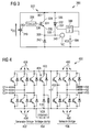
- Fig. 4 illustrates an AC-to-AC converter 450 for converting a variable frequency AC-voltage applied at terminals G1, G2 and G3 to a fixed frequency AC-voltage supplied to the terminals N1, N2 and N3 into which a voltage clamp according to an embodiment may be integrated.
- the converter 450 comprises a first section 452 (also referred to as generator bridge), a voltage clamp 454 and a second section 456 (also referred to as network bridge).
- a conventional voltage clamp is illustrated comprising only one IGBT 424 which is controlled by a not illustrated control circuit.
- the IGBT 424 may be replaced by the circuit 100, illustrated in Fig. 1 , the circuit 200 illustrated in Fig. 2 , or the circuit 300 illustrated in Fig.
- the first section 452 comprises six IGBTs 458 which are connected to the terminals G1, G2 and G3 such as to generate a substantially direct current (DC) voltage between the first DC voltage terminal 403 and the second DC voltage terminal 410.
- the second section 456 comprises also six IGBTs 460 which are connected such as to convert the DC voltage to a fixed AC-voltage supplied to the terminals N1, N2 and N3.
- the converter 450 may in particular be used for a wind turbine.
Priority Applications (4)
| Application Number | Priority Date | Filing Date | Title |
|---|---|---|---|
| EP10194148A EP2463976A1 (fr) | 2010-12-08 | 2010-12-08 | Circuit et procédé de régulation de tension CC et convertisseur d'alimentation |
| US13/307,332 US8680701B2 (en) | 2010-12-08 | 2011-11-30 | Circuit and method for regulating a DC voltage applied between a first and second DC voltage terminal |
| CA2760951A CA2760951A1 (fr) | 2010-12-08 | 2011-12-06 | Circuit et procede de regulation de tension pour courant continu, et convertisseur de puissance |
| CN201110405605.5A CN102545639B (zh) | 2010-12-08 | 2011-12-08 | 用于调节直流电压的电路和方法以及电力转换器 |
Applications Claiming Priority (1)
| Application Number | Priority Date | Filing Date | Title |
|---|---|---|---|
| EP10194148A EP2463976A1 (fr) | 2010-12-08 | 2010-12-08 | Circuit et procédé de régulation de tension CC et convertisseur d'alimentation |
Publications (1)
| Publication Number | Publication Date |
|---|---|
| EP2463976A1 true EP2463976A1 (fr) | 2012-06-13 |
Family
ID=44645280
Family Applications (1)
| Application Number | Title | Priority Date | Filing Date |
|---|---|---|---|
| EP10194148A Withdrawn EP2463976A1 (fr) | 2010-12-08 | 2010-12-08 | Circuit et procédé de régulation de tension CC et convertisseur d'alimentation |
Country Status (4)
| Country | Link |
|---|---|
| US (1) | US8680701B2 (fr) |
| EP (1) | EP2463976A1 (fr) |
| CN (1) | CN102545639B (fr) |
| CA (1) | CA2760951A1 (fr) |
Cited By (2)
| Publication number | Priority date | Publication date | Assignee | Title |
|---|---|---|---|---|
| EP2997634A4 (fr) * | 2013-05-15 | 2017-05-10 | Oeco Llc | Dispositif de suppression de tension transitoire active |
| US10042011B2 (en) | 2015-07-27 | 2018-08-07 | Siemens Aktiengesellschaft | Method to detect or monitor the demagnetization of a magnet |
Families Citing this family (12)
| Publication number | Priority date | Publication date | Assignee | Title |
|---|---|---|---|---|
| EP2522075B1 (fr) * | 2010-04-08 | 2017-09-13 | Siemens Aktiengesellschaft | Circuit et procédé destinés à protéger un interrupteur pouvant être commandé |
| EP2463996B1 (fr) * | 2010-12-08 | 2013-06-05 | Siemens Aktiengesellschaft | Convertisseur CA/CA et procédé de conversion d'une tension CA de première fréquence en une tension CA de seconde fréquence |
| EP2793392B1 (fr) * | 2013-04-16 | 2023-07-12 | Siemens Aktiengesellschaft | Contrôleur pour convertisseur de fréquence |
| CN104237761B (zh) * | 2013-06-13 | 2018-05-04 | 通用电气公司 | 绝缘栅双极型晶体管的失效模式检测及保护的系统和方法 |
| CN108925140B (zh) * | 2016-02-05 | 2020-12-18 | Abb瑞士股份有限公司 | 对风力涡轮设施进行加热 |
| US10044305B2 (en) * | 2016-12-22 | 2018-08-07 | Hamilton Sundstrand Corporation | Controlling aircraft VFG over voltage under fault or load-shed |
| DE102018202661A1 (de) * | 2018-02-22 | 2019-08-22 | Zf Friedrichshafen Ag | Verfahren und Vorrichtung zum Entladen eines Zwischenkreiskondensators |
| DE102018115295A1 (de) * | 2018-06-26 | 2020-01-02 | Valeo Siemens Eautomotive Germany Gmbh | Steuerungseinrichtung sowie Verfahren zum Entladen eines Zwischenkreiskondensators, Stromrichter und Fahrzeug |
| CN109546638B (zh) * | 2018-10-22 | 2020-07-28 | 南京南瑞继保电气有限公司 | 一种直流耗能装置以及控制方法 |
| US11394264B2 (en) | 2020-01-21 | 2022-07-19 | Itt Manufacturing Enterprises Llc | Motor assembly for driving a pump or rotary device with a low inductance resistor for a matrix converter |
| US11451156B2 (en) | 2020-01-21 | 2022-09-20 | Itt Manufacturing Enterprises Llc | Overvoltage clamp for a matrix converter |
| CN114123787B (zh) * | 2021-11-09 | 2023-10-10 | 珠海格力电器股份有限公司 | 开关电源电路及开关电源 |
Citations (6)
| Publication number | Priority date | Publication date | Assignee | Title |
|---|---|---|---|---|
| DE19833490A1 (de) * | 1998-07-24 | 2000-01-27 | Siemens Ag | Spannungszwischenkreisumrichter |
| WO2003065567A1 (fr) * | 2002-01-29 | 2003-08-07 | Vestas Wind Systems A/S | Circuit conçu pour etre utilise dans une installation d'energie eolienne |
| DE102007005165A1 (de) * | 2006-01-31 | 2007-08-02 | General Electric Company | Verfahren, Vorrichtung und Computerprogrammprodukt zur Stromeinspeisung |
| US20090079193A1 (en) * | 2004-12-28 | 2009-03-26 | Vestas Wind Systems A/S | Method of controlling a wind turbine connected to an electric utility grid |
| US20090273185A1 (en) * | 2005-11-21 | 2009-11-05 | Josu Ruiz Flores | System for Controlling and Protecting Against Symmetrical and Asymmetrical Faults for Asynchronous-Type Generators |
| WO2010045964A1 (fr) * | 2008-10-20 | 2010-04-29 | Woodward Seg Gmbh & Co. Kg | Système de protection d’une machine à induction à double alimentation |
Family Cites Families (6)
| Publication number | Priority date | Publication date | Assignee | Title |
|---|---|---|---|---|
| US4812729A (en) * | 1986-08-19 | 1989-03-14 | Hitachi Ltd. | Protecting apparatus for secondary excitation type variable speed AC generator/motor |
| IN172421B (fr) * | 1989-03-14 | 1993-07-24 | Kone Elevator Gmbh | |
| FI116174B (fi) * | 2003-04-08 | 2005-09-30 | Abb Oy | Kokoonpano ja menetelmä suuntaajavälineiden suojaamiseksi |
| EP1499009B1 (fr) * | 2003-07-15 | 2007-10-31 | Gamesa Innovation & Technology, S.L. Unipersonal | Commande et protection d'un système générateur à induction à double alimentation |
| CN201075834Y (zh) * | 2007-06-12 | 2008-06-18 | 上海申传电气有限公司 | 一种采煤机牵引系统大功率交流变频装置 |
| US7709972B2 (en) * | 2007-08-30 | 2010-05-04 | Mitsubishi Heavy Industries, Ltd. | Wind turbine system for satisfying low-voltage ride through requirement |
-
2010
- 2010-12-08 EP EP10194148A patent/EP2463976A1/fr not_active Withdrawn
-
2011
- 2011-11-30 US US13/307,332 patent/US8680701B2/en active Active
- 2011-12-06 CA CA2760951A patent/CA2760951A1/fr not_active Abandoned
- 2011-12-08 CN CN201110405605.5A patent/CN102545639B/zh not_active Expired - Fee Related
Patent Citations (6)
| Publication number | Priority date | Publication date | Assignee | Title |
|---|---|---|---|---|
| DE19833490A1 (de) * | 1998-07-24 | 2000-01-27 | Siemens Ag | Spannungszwischenkreisumrichter |
| WO2003065567A1 (fr) * | 2002-01-29 | 2003-08-07 | Vestas Wind Systems A/S | Circuit conçu pour etre utilise dans une installation d'energie eolienne |
| US20090079193A1 (en) * | 2004-12-28 | 2009-03-26 | Vestas Wind Systems A/S | Method of controlling a wind turbine connected to an electric utility grid |
| US20090273185A1 (en) * | 2005-11-21 | 2009-11-05 | Josu Ruiz Flores | System for Controlling and Protecting Against Symmetrical and Asymmetrical Faults for Asynchronous-Type Generators |
| DE102007005165A1 (de) * | 2006-01-31 | 2007-08-02 | General Electric Company | Verfahren, Vorrichtung und Computerprogrammprodukt zur Stromeinspeisung |
| WO2010045964A1 (fr) * | 2008-10-20 | 2010-04-29 | Woodward Seg Gmbh & Co. Kg | Système de protection d’une machine à induction à double alimentation |
Cited By (2)
| Publication number | Priority date | Publication date | Assignee | Title |
|---|---|---|---|---|
| EP2997634A4 (fr) * | 2013-05-15 | 2017-05-10 | Oeco Llc | Dispositif de suppression de tension transitoire active |
| US10042011B2 (en) | 2015-07-27 | 2018-08-07 | Siemens Aktiengesellschaft | Method to detect or monitor the demagnetization of a magnet |
Also Published As
| Publication number | Publication date |
|---|---|
| CA2760951A1 (fr) | 2012-06-08 |
| US20120147634A1 (en) | 2012-06-14 |
| US8680701B2 (en) | 2014-03-25 |
| CN102545639B (zh) | 2016-04-06 |
| CN102545639A (zh) | 2012-07-04 |
Similar Documents
| Publication | Publication Date | Title |
|---|---|---|
| US8680701B2 (en) | Circuit and method for regulating a DC voltage applied between a first and second DC voltage terminal | |
| US11631973B2 (en) | Adjustable speed drive with integrated solid-state circuit breaker and method of operation thereof | |
| CN106253649B (zh) | 具有短路装置的电力变换器子模块和具有其的电力变换器 | |
| EP3706276B1 (fr) | Procédé d'inspection et dispositif de commande de groupe de valves à thyristors de dérivation | |
| EP1811645B1 (fr) | Procede et appareil de protection de circuit d'alimentation electrique | |
| US10186952B2 (en) | Power conversion device | |
| RU2461912C1 (ru) | Шунтирующий модуль | |
| EP1858148A1 (fr) | Inverseur cooperatif de systeme | |
| US9998060B2 (en) | System and method for capacitor fault energy interruption in adjustable speed drives | |
| EP3627685B1 (fr) | Dispositif de compensation de puissance réactive et son procédé de commande | |
| US11881764B2 (en) | Short-circuit protection systems and methods for flying capacitor based buck-boost converters | |
| US11356013B2 (en) | Method of short-circuiting a faulty converter submodule and power converter supporting same | |
| EP3621190A1 (fr) | Procédé de protection amélioré pour une cellule maillon de chaîne ou mmc à base de module semi-conducteur par une protection par court-circuit cc | |
| Jakka et al. | Protection design considerations of a 10 kV SiC MOSFET enabled mobile utilities support equipment based solid state transformer (MUSE-SST) | |
| US10333386B2 (en) | Method for detecting a voltage collapse | |
| JP2009011117A (ja) | 電力変換装置 | |
| EP2878964B1 (fr) | Détection de diodes court-circuitées | |
| EP2487781A2 (fr) | Convertisseur de puissance et procédé de fonctionnement avec son circuit de protection | |
| US11271495B2 (en) | Intermediate circuit coupling in drive assemblies | |
| GB2564700A (en) | A power electronics module and a method of detecting a fault in a power electronics module | |
| Sallam et al. | New measurement technique for modular multilevel converter with IGBT open-circuit failure detection and tolerance control for three-level submodule | |
| GB2564701A (en) | A power electronics module and a method of protecting a solid state switching device in a power electronics module | |
| US9979279B2 (en) | DC-DC converter input voltage high-energy transient clamping topology | |
| JP2007181357A (ja) | 過電流検出機能を備えたコンデンサ入力型整流回路及びそれを用いたインバータ装置 | |
| Salzrnanri et al. | Status Identification for Improved Gate Driving and Protection of Power GTOs |
Legal Events
| Date | Code | Title | Description |
|---|---|---|---|
| PUAI | Public reference made under article 153(3) epc to a published international application that has entered the european phase |
Free format text: ORIGINAL CODE: 0009012 |
|
| AK | Designated contracting states |
Kind code of ref document: A1 Designated state(s): AL AT BE BG CH CY CZ DE DK EE ES FI FR GB GR HR HU IE IS IT LI LT LU LV MC MK MT NL NO PL PT RO RS SE SI SK SM TR |
|
| AX | Request for extension of the european patent |
Extension state: BA ME |
|
| 17P | Request for examination filed |
Effective date: 20120709 |
|
| RAP1 | Party data changed (applicant data changed or rights of an application transferred) |
Owner name: SIEMENS AKTIENGESELLSCHAFT |
|
| RAP1 | Party data changed (applicant data changed or rights of an application transferred) |
Owner name: SIEMENS AKTIENGESELLSCHAFT |
|
| STAA | Information on the status of an ep patent application or granted ep patent |
Free format text: STATUS: THE APPLICATION IS DEEMED TO BE WITHDRAWN |
|
| 18D | Application deemed to be withdrawn |
Effective date: 20170701 |