EP2463933A2 - Battery - Google Patents
Battery Download PDFInfo
- Publication number
- EP2463933A2 EP2463933A2 EP11192729A EP11192729A EP2463933A2 EP 2463933 A2 EP2463933 A2 EP 2463933A2 EP 11192729 A EP11192729 A EP 11192729A EP 11192729 A EP11192729 A EP 11192729A EP 2463933 A2 EP2463933 A2 EP 2463933A2
- Authority
- EP
- European Patent Office
- Prior art keywords
- cover
- gasket
- external terminal
- outside
- engagement portion
- Prior art date
- Legal status (The legal status is an assumption and is not a legal conclusion. Google has not performed a legal analysis and makes no representation as to the accuracy of the status listed.)
- Granted
Links
Images


Classifications
-
- H—ELECTRICITY
- H01—ELECTRIC ELEMENTS
- H01M—PROCESSES OR MEANS, e.g. BATTERIES, FOR THE DIRECT CONVERSION OF CHEMICAL ENERGY INTO ELECTRICAL ENERGY
- H01M50/00—Constructional details or processes of manufacture of the non-active parts of electrochemical cells other than fuel cells, e.g. hybrid cells
- H01M50/50—Current conducting connections for cells or batteries
- H01M50/543—Terminals
-
- H—ELECTRICITY
- H01—ELECTRIC ELEMENTS
- H01M—PROCESSES OR MEANS, e.g. BATTERIES, FOR THE DIRECT CONVERSION OF CHEMICAL ENERGY INTO ELECTRICAL ENERGY
- H01M50/00—Constructional details or processes of manufacture of the non-active parts of electrochemical cells other than fuel cells, e.g. hybrid cells
- H01M50/50—Current conducting connections for cells or batteries
- H01M50/528—Fixed electrical connections, i.e. not intended for disconnection
-
- H—ELECTRICITY
- H01—ELECTRIC ELEMENTS
- H01M—PROCESSES OR MEANS, e.g. BATTERIES, FOR THE DIRECT CONVERSION OF CHEMICAL ENERGY INTO ELECTRICAL ENERGY
- H01M10/00—Secondary cells; Manufacture thereof
- H01M10/05—Accumulators with non-aqueous electrolyte
- H01M10/058—Construction or manufacture
- H01M10/0585—Construction or manufacture of accumulators having only flat construction elements, i.e. flat positive electrodes, flat negative electrodes and flat separators
-
- H—ELECTRICITY
- H01—ELECTRIC ELEMENTS
- H01M—PROCESSES OR MEANS, e.g. BATTERIES, FOR THE DIRECT CONVERSION OF CHEMICAL ENERGY INTO ELECTRICAL ENERGY
- H01M10/00—Secondary cells; Manufacture thereof
- H01M10/06—Lead-acid accumulators
- H01M10/12—Construction or manufacture
-
- H—ELECTRICITY
- H01—ELECTRIC ELEMENTS
- H01M—PROCESSES OR MEANS, e.g. BATTERIES, FOR THE DIRECT CONVERSION OF CHEMICAL ENERGY INTO ELECTRICAL ENERGY
- H01M50/00—Constructional details or processes of manufacture of the non-active parts of electrochemical cells other than fuel cells, e.g. hybrid cells
- H01M50/10—Primary casings; Jackets or wrappings
- H01M50/147—Lids or covers
-
- H—ELECTRICITY
- H01—ELECTRIC ELEMENTS
- H01M—PROCESSES OR MEANS, e.g. BATTERIES, FOR THE DIRECT CONVERSION OF CHEMICAL ENERGY INTO ELECTRICAL ENERGY
- H01M50/00—Constructional details or processes of manufacture of the non-active parts of electrochemical cells other than fuel cells, e.g. hybrid cells
- H01M50/10—Primary casings; Jackets or wrappings
- H01M50/183—Sealing members
-
- H—ELECTRICITY
- H01—ELECTRIC ELEMENTS
- H01M—PROCESSES OR MEANS, e.g. BATTERIES, FOR THE DIRECT CONVERSION OF CHEMICAL ENERGY INTO ELECTRICAL ENERGY
- H01M50/00—Constructional details or processes of manufacture of the non-active parts of electrochemical cells other than fuel cells, e.g. hybrid cells
- H01M50/50—Current conducting connections for cells or batteries
- H01M50/543—Terminals
- H01M50/547—Terminals characterised by the disposition of the terminals on the cells
- H01M50/55—Terminals characterised by the disposition of the terminals on the cells on the same side of the cell
-
- H—ELECTRICITY
- H01—ELECTRIC ELEMENTS
- H01M—PROCESSES OR MEANS, e.g. BATTERIES, FOR THE DIRECT CONVERSION OF CHEMICAL ENERGY INTO ELECTRICAL ENERGY
- H01M50/00—Constructional details or processes of manufacture of the non-active parts of electrochemical cells other than fuel cells, e.g. hybrid cells
- H01M50/50—Current conducting connections for cells or batteries
- H01M50/543—Terminals
- H01M50/552—Terminals characterised by their shape
- H01M50/553—Terminals adapted for prismatic, pouch or rectangular cells
-
- Y—GENERAL TAGGING OF NEW TECHNOLOGICAL DEVELOPMENTS; GENERAL TAGGING OF CROSS-SECTIONAL TECHNOLOGIES SPANNING OVER SEVERAL SECTIONS OF THE IPC; TECHNICAL SUBJECTS COVERED BY FORMER USPC CROSS-REFERENCE ART COLLECTIONS [XRACs] AND DIGESTS
- Y02—TECHNOLOGIES OR APPLICATIONS FOR MITIGATION OR ADAPTATION AGAINST CLIMATE CHANGE
- Y02E—REDUCTION OF GREENHOUSE GAS [GHG] EMISSIONS, RELATED TO ENERGY GENERATION, TRANSMISSION OR DISTRIBUTION
- Y02E60/00—Enabling technologies; Technologies with a potential or indirect contribution to GHG emissions mitigation
- Y02E60/10—Energy storage using batteries
-
- Y—GENERAL TAGGING OF NEW TECHNOLOGICAL DEVELOPMENTS; GENERAL TAGGING OF CROSS-SECTIONAL TECHNOLOGIES SPANNING OVER SEVERAL SECTIONS OF THE IPC; TECHNICAL SUBJECTS COVERED BY FORMER USPC CROSS-REFERENCE ART COLLECTIONS [XRACs] AND DIGESTS
- Y02—TECHNOLOGIES OR APPLICATIONS FOR MITIGATION OR ADAPTATION AGAINST CLIMATE CHANGE
- Y02P—CLIMATE CHANGE MITIGATION TECHNOLOGIES IN THE PRODUCTION OR PROCESSING OF GOODS
- Y02P70/00—Climate change mitigation technologies in the production process for final industrial or consumer products
- Y02P70/50—Manufacturing or production processes characterised by the final manufactured product
Definitions
- Fig. 5 is a perspective view showing the cover, as viewed from the bottom and cross-sectional views showing the cover, as viewed in partly enlargement;
- An engagement portion 12 which is formed into a substantially rectangular shape, as viewed on plane, and expands upward, is formed at the lower surface at each of both ends of the cover 3.
- a shallow guide recess 12b is formed around a engaged recess 12a at the lower surface except one side.
- a through hole 12c is formed at the center of a ceiling constituting the engaged recess 12a.
- An external terminal 14 and a current collector 13 are adapted to fit to the engaged recess 12 and the guide recess 12b via a lower gasket 15 and an upper gasket 16, respectively.
Landscapes
- Chemical & Material Sciences (AREA)
- Chemical Kinetics & Catalysis (AREA)
- Electrochemistry (AREA)
- General Chemical & Material Sciences (AREA)
- Engineering & Computer Science (AREA)
- Manufacturing & Machinery (AREA)
- Connection Of Batteries Or Terminals (AREA)
- Sealing Battery Cases Or Jackets (AREA)
Abstract
Description
- The present invention relates to a battery featured by a sealing structure at a connection portion of an external terminal, that is, a structure of an outside gasket.
- There has been conventionally known, as a battery, a configuration in which a riveted terminal is fixed to a cover plate via an outer insulating/preventing plate (see, for example,
JP-A-2003-157812 - However, the conventional battery includes the outer insulating plate which is merely brought into contact with the upper surface of a flat cover but does not include any structure for restricting movement in a rotational direction. Therefore, the outer insulating plate may be positionally deviated in the rotational direction when the riveted terminal is fixed, thereby making assembly work cumbersome.
- An object of the present invention is to provide a battery configured such that an outside gasket for insulating a cover from an external terminal to be fixed thereto is readily fixed to the cover irrespective of a simple structure.
- According to a first aspect of the invention, a battery includes: a battery case which contains a power generating element therein and whose top surface is opened; a cover which closes the top surface; at which an external terminal exposed to the outside is disposed at the outer surface of the cover via an outside gasket, the cover having an engagement portion which expands outward and is formed into a shape except a circle, and
the outside gasket having a recess to be engaged to the engagement portion. - When the external terminal is fixed to the cover, the recess of the outside gasket is engaged to the engagement portion formed at the cover, thereby preventing positional deviation in a rotational direction. Consequently, it is possible to efficiently fix the external terminal.
- According to a second aspect of the invention, a battery includes: a battery case which contains a power generating element therein and whose top surface is opened; a cover which closes the opening, the cover having a current collector to be connected to the power generating element via an inside gasket and having an external terminal exposed to the outside fixed via an outside gasket, the cover has: a through hole and an engagement portion which expands outward and is formed into a shape except a circle, the external terminal has a shaft and plate portion at the other end of the shaft, the external terminal being caulked at one end of the shaft through the outside gasket, the cover, the inside gasket, and the current collector; and the outside gasket having a recess to be engaged to the engagement portion and a tubular portion which is inserted into the through hole formed in the cover, is fitted to the shaft of the external terminal, and is fitted to a through hole formed in the inside gasket.
- In the outside gasket, the engagement portion formed at the cover is located in the recess, thereby preventing the positional deviation in the rotational direction. Consequently, when the cover, the inside gasket, and the current collector are assembled via the shaft of the external terminal, followed by securely caulking, the workability can be enhanced without any need of taking care of the positional deviation of the outside gasket.
- The outside gasket may include the recess and another recess, to which the plate portion of the external terminal is arranged, by dividing a frame member via a partition.
- Since the plate portion of the external terminal is arranged in the recess, the external terminal is not positionally deviated by securely caulking. Further, even if the rotational power is operated to the external terminal as the opposed end of the shaft is the plate portion, the rotation of the external terminal is prevented.
- The cover may have a lock portion formed at the outer surface thereof, and the outside gasket may have a tongue piece extending along the cover formed therein, the tongue piece having a locked portion to be locked to the lock portion in the state in which the outside gasket is engaged to the engagement portion in the cover.
- With this configuration, the outside gasket can be prevented from being positionally deviated in the rotational direction by locking the locked portion of the tongue piece to the lock portion in the cover.
-
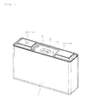
Fig. 1 is a perspective view showing a battery in accordance with the present embodiment; -
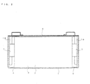
Fig. 2 is a front cross-sectional view showing the battery in accordance with the present embodiment; -
Fig. 3 is a perspective view showing a cover shown inFIG. 1 , as viewed from the top; -
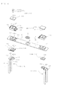
Fig. 4 is an exploded perspective view showing the cover shown inFIG. 3 ; -
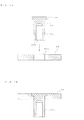
Fig. 5 is a perspective view showing the cover, as viewed from the bottom and cross-sectional views showing the cover, as viewed in partly enlargement; -
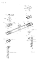
Fig. 6 is an exploded perspective view shown inFIG. 5 ; and -
Figs. 7A and 7B are cross-sectional views illustrating fabrication processes for a negative electrode terminal shown inFIG. 4 . - Hereinafter, an embodiment according to the present invention will be described with reference to the attached drawings. In the following description, the terms indicating specific directions or positions (including, for example, "above," "below," "side," and "end") are used, as required. Here, the use of the terms is directed to facilitating the understanding of the invention referring to the drawings, and therefore, the meanings of the terms should not restrict the technical scope of the present invention. Moreover, the following description is merely an essential example, and therefore, should not intend to restrict the present invention and its application or usage.
-
FIG. 1 shows a nonaqueous electrolytic secondary battery. The nonaqueous electrolytic secondary battery contains a power generatingelement 2 inside of abattery case 1, and is sealed with acover 3, as shown inFIG. 2 . Here, thebattery case 1 and thecover 3 constitute an envelope member. - The
battery case 1 is formed into a rectangular parallelepiped shape opened at the upper surface thereof, and is made of aluminum or an aluminum alloy, etc. - In the power generating
element 2, aseparator 6 made of a porous resin film is interposed between anegative electrode 4 including a copper foil and apositive electrode 5 including an aluminum foil, like the prior art, although its details will not be shown. All of these members are formed into a belt shape, and further, thenegative electrode 4 and thepositive electrode 5 are flat wound in such a manner as to be contained inside of thebattery case 1 in the state in which they are positionally deviated oppositely with respect to theseparator 6 in a widthwise direction. As described later, a negative electrodecurrent collector 18 is connected to thenegative electrode 4 via aclip 7 whereas a positive electrodecurrent collector 19 is connected to thepositive electrode 5 via anotherclip 7. - As shown in
FIGS. 3 to 6 , thecover 3 is made of a metallic elongated plate formed into a rectangular shape, as viewed on plane. A substantiallyelliptic opening 8 having a step from the upside is formed at the center of thecover 3. Asafety valve 9 made of a synthetic resin is engaged to the opening 8. A substantially H-shaped thin portion is formed at thesafety valve 9. The thin portion is torn in the case of an abnormal increase in inner pressure, so that pressure can be decreased. - A small-diameter
liquid injection hole 10 is formed at one end of thecover 3, and it is designed to be closed via a plug 11 after liquid injection. - An
engagement portion 12, which is formed into a substantially rectangular shape, as viewed on plane, and expands upward, is formed at the lower surface at each of both ends of thecover 3. In theengagement portion 12, a shallow guide recess 12b is formed around a engaged recess 12a at the lower surface except one side. Moreover, a through hole 12c is formed at the center of a ceiling constituting the engaged recess 12a. Anexternal terminal 14 and acurrent collector 13 are adapted to fit to theengaged recess 12 and the guide recess 12b via alower gasket 15 and anupper gasket 16, respectively. -
Lock projections 17 projecting upward from two portions in the widthwise direction are formed in the vicinity of the inside of each of theengagement portion 12 in thecover 3. Each of thelock projections 17 is formed into a bottomed tubular shape at the same time when thecover 3 is pressed. Theupper gasket 15, described later, is locked to thelock projections 17, to be thus positioned in a rotational direction. - The
current collectors 13 include the negativecurrent collector 18 made of copper and the positivecurrent collector 19 made of aluminum. In thecurrent collector 13, aconnection receiver 20 and legs 21 extending from both sides of theconnection receiver 20 are formed by pressing a metallic elongated plate material. Theconnection receiver 20 is constituted of afitting portion 22 to be engaged to the recess formed at thecover 3 and a mount portion 23 continuous to thefitting portion 22. Thefitting portion 22 is formed into a planar shape, and has a through hole 22a at the center thereof and aguide edge 24 extending in a vertical direction at the circumferential edge except one side continuous to the mount portion 23. The side of the mount portion 23 functions as acontinuous portion 25 extending further beyond theguide edge 24, and thus, reaches the mount portion 23. Theguide edge 24 and thecontinuous portion 25 satisfactorily enhance the rigidity of theconnection receiver 20 in thecurrent collector 13. - The legs 21 extend in the vertical direction from both side edges of the mount portion 23 along both side surfaces of the power generating
element 2. The legs 21 are connected to thepositive electrode 5 or thenegative electrode 4 in the power generatingelement 2 via theclip 7. Positional deviation can be prevented since theclip 7 is held between the inner surfaces, opposite to each other, of thebattery case 1. - The
external terminals 14 include a negative electrodeexternal terminal 28 and a positive electrodeexternal terminal 29. Theexternal terminal 14 includes aflat plate 30 and a shaft 31 extending downward from the center at a lower surface thereof. To a surface (an exposed surface) of theflat plate 30 is welded a bus bar, not shown. - As shown in
FIG. 7 , the negative electrodeexternal terminal 28 is formed of analuminum plate 32 formed into a rectangular shape, as viewed on plane, and acopper rivet 33. That is to say, a shaft 33a of therivet 33 is inserted into a through hole 32a formed at the center of thealuminum plate 32, and then, a flange 33b is press-engaged into the through hole 32a by pressing. The dimension of an inner diameter of the through hole 32a formed at theplate 32 is slightly greater than that of an outer diameter of the shaft 33a of therivet 33 and sufficiently smaller than that of an outer diameter of the flange 33b. As a consequence, the flange 33b presses and enlarges the through hole 32a by press-fitting, to be thus turned to a press-engaged state, and further, the press-enlarged portion is brought into press-contact with the shaft 33a, to be thus integrated therewith. Moreover, a circular recess 33c is formed at the center of the tip surface of the shaft 33a in therivet 33. The shaft 33a is inserted into the respective through holes of theupper gasket 15, theengagement portion 12 of thecover 3, thelower gasket 16, and the negative electrodecurrent collector 18 in a later-described manner, and then, the recess 33c is pressed and enlarged while holding the members therein, followed by securely caulking. - The
upper gasket 15 is made of a synthetic resin, wherein the inner space of a frame formed into a rectangular shape, as viewed on plane, is divided into an upper terminal holding recess 37 and a lower containing recess 38 via apartition 36.Tongue pieces 39 extend sideways from one of sides constituting a lower opening edge. A tubular portion 36a extending downward from the ceiling is formed at the center of thepartition 36. The tubular portion 36a is engaged to a through hole 40a formed at thelower gasket 16 through the through hole 12c formed at theengagement portion 12. A lock hole 39a is formed in each of the twotongue pieces 39, and thus, is engaged to thelock projection 17 formed in thecover 3. Theupper gasket 15 conforms to theengagement portion 12 in thecover 3 formed into the rectangular shape, as viewed on plane, and therefore, it can be prevented from being positionally deviated in the rotational direction only by its placement on theengagement portion 12. In addition, the insertion of thelock projection 17 into the lock hole 39a can securely prevent any positional deviation in the rotational direction. - The
lower gasket 16 is a plate formed into a rectangular shape, as viewed on plane, and further, is made of a synthetic resin having a through hole 16a at the center thereof. Thelower gaskets 16 on the negative electrode side and the positive electrode side are slightly different from each other in shape. - A
lower gasket 16A on the negative electrode side includes an expandedportion 40 to be contained inside of the engaged recess 12a formed at theengagement portion 12 in thecover 3 and a flat portion 41 continuous to the expandedportion 40. The expandedportion 40 is formed into a shape in conformity with the inner surface of the engaged recess 12a of theengagement portion 12 except one side thereof, and further, the through hole 40a is formed at the center thereof. The flat portion 41 is arranged to the guide recess 12b of theengagement portion 12. Thelower gasket 16A on the negative electrode side is contained from below inside of the engaged recess 12a constituting theengagement portion 12 in thecover 3, and thus, is held between thecover 3 and the negative electrodecurrent collector 18. In this held state, thelower gasket 16A aims at the insulation between the negative electrodecurrent collector 18 and thecover 3, and further, seals the through hole 12c formed in theengagement portion 12 in thecover 3 together with theupper gasket 15. - On the other hand, a lower gasket 16B on the positive electrode side is formed into a flat shape, and further, has a through hole 16a at the center thereof, and thus, is contained inside of the engaged recess 12a constituting the
engagement portion 12. The lower gasket 16B on the positive electrode side seals the through hole 12c formed in theengagement portion 12 in thecover 3 together with theupper gasket 15. - With the battery having the above-described configuration, the positional deviation in the rotational direction can be prevented only by locating the containing recess 38 of the
upper gasket 15 at theengagement portion 12 in thecover 3. Consequently, when the shaft 31 of theexternal terminal 14 is inserted into the respective through holes of theupper gasket 15, thecover 3, thelower gasket 16, and thecurrent collector 13, followed by securely caulking, theupper gasket 15 can be prevented from being positionally deviated. Thus, it is possible to enhance workability of a series of assembling work. - Incidentally, the present invention is not limited to the configuration described in the embodiment, and it may be variously modified.
- For example, the
upper gasket 15 is not limited to the rectangular shape, as viewed on plane, but it may be formed into various shapes, for example, a polygon such as a triangle and a pentagon or more, and an ellipse other than a circle, as viewed on plane. In summary, theupper gasket 15 may be configured in any manners as long as the positional deviation in the rotational direction can be prevented when it is attached. In some case, theupper gasket 15 may not conform to the shape of theengagement portion 12 in thecover 3. - Additionally, although the
battery case 1 is formed into the rectangular parallelepiped shape, theengagement portion 12 in thecover 3 and theupper gasket 15 such configured as described above can be adopted even if thebattery case 1 may be formed into other shapes such as a cylindrical shape. - Thus, the structure of the
external terminal 14 for the battery according to the present invention may be applied to various batteries such as a lithium ion battery and a lead storage battery, etc. - According to the present invention, the engagement portion formed into a shape other than a circle, as viewed on plane, is formed in the cover, and further, the recess formed at the outside gasket is engaged to the engagement portion. Thus, when the external terminal and the like are fixed, the workability can be enhanced without any positional deviation of the outside gasket.
Claims (5)
- A battery comprising:a battery case which contains a power generating element therein and whose top surface is opened;a cover which closes the top surface; at which an external terminal exposed to the outside is disposed at the outer surface of the cover via an outside gasket, the cover having an engagement portion which expands outward and is formed into a shape except a circle, andthe outside gasket having a recess to be engaged to the engagement portion.
- A battery comprising:a battery case which contains a power generating element therein and whose top surface is opened;a cover which closes the opening, the cover having a current collector to be connected to the power generating element via an inside gasket and having an external terminal exposed to the outside fixed via an outside gasket, the cover having a through hole and an engagement portion which expands outward and is formed into a shape except a circle,the external terminal has a shaft and plate portion at the other end of the shaft, the external terminal being caulked at one end of the shaft through the outside gasket, the cover, the inside gasket, and the current collector; andthe outside gasket having a recess to be engaged to the engagement portion and a tubular portion which is inserted into the through hole formed in the cover, is fitted to the shaft of the external terminal, and is fitted to a through hole formed in the inside gasket.
- A battery according to claim 1 or 2, wherein the outside gasket includes the recess and another recess, to which the plate portion of the external terminal is arranged, by dividing a frame member via a partition.
- A battery according to any one of claims 1 to 3, wherein
the cover has a lock portion formed at the outer surface thereof, and
the outside gasket has a tongue piece extending along the cover formed therein, the tongue piece having a locked portion to be locked to the lock portion in the state in which the outside gasket is engaged to the engagement portion in the cover. - A battery according to claim 3, wherein
the frame member is formed into a rectangular shape, as viewed on plane.
Applications Claiming Priority (1)
| Application Number | Priority Date | Filing Date | Title |
|---|---|---|---|
| JP2010276204A JP5699578B2 (en) | 2010-12-10 | 2010-12-10 | battery |
Publications (3)
| Publication Number | Publication Date |
|---|---|
| EP2463933A2 true EP2463933A2 (en) | 2012-06-13 |
| EP2463933A3 EP2463933A3 (en) | 2014-04-09 |
| EP2463933B1 EP2463933B1 (en) | 2016-05-25 |
Family
ID=45218442
Family Applications (1)
| Application Number | Title | Priority Date | Filing Date |
|---|---|---|---|
| EP11192729.9A Active EP2463933B1 (en) | 2010-12-10 | 2011-12-09 | Battery |
Country Status (5)
| Country | Link |
|---|---|
| US (1) | US8795882B2 (en) |
| EP (1) | EP2463933B1 (en) |
| JP (1) | JP5699578B2 (en) |
| KR (1) | KR101912725B1 (en) |
| CN (1) | CN102569683B (en) |
Families Citing this family (22)
| Publication number | Priority date | Publication date | Assignee | Title |
|---|---|---|---|---|
| JP5609610B2 (en) * | 2010-12-10 | 2014-10-22 | 株式会社Gsユアサ | battery |
| JP6014990B2 (en) * | 2010-12-10 | 2016-10-26 | 株式会社Gsユアサ | Battery, current collector, and current collector manufacturing method |
| KR101243546B1 (en) | 2011-03-02 | 2013-03-20 | 로베르트 보쉬 게엠베하 | Rechargeable battery and battery pack having the same |
| JP5592844B2 (en) * | 2011-06-28 | 2014-09-17 | 株式会社リチウムエナジージャパン | Electricity storage element |
| KR101711978B1 (en) * | 2011-10-05 | 2017-03-06 | 삼성에스디아이 주식회사 | Rechargeable battery |
| JP6179089B2 (en) | 2011-11-29 | 2017-08-16 | 株式会社Gsユアサ | Power storage device and method for manufacturing power storage device |
| KR101726110B1 (en) * | 2012-11-15 | 2017-04-11 | 제이에무에나지 가부시키가이샤 | Electricity storage device and electricity storage module |
| US9034513B2 (en) | 2013-03-11 | 2015-05-19 | Lithium Energy Japan | Energy storage device |
| DE102013206503A1 (en) * | 2013-04-12 | 2014-10-16 | Robert Bosch Gmbh | Device for receiving battery cells, battery module and motor vehicle |
| JP2014150047A (en) * | 2013-08-08 | 2014-08-21 | Hitachi Vehicle Energy Ltd | Electricity storage element |
| KR101724003B1 (en) | 2013-09-12 | 2017-04-06 | 삼성에스디아이 주식회사 | Rechargeable battery |
| JP6270511B2 (en) * | 2014-01-30 | 2018-01-31 | トヨタ自動車株式会社 | Secondary battery and method for manufacturing secondary battery |
| JP6601684B2 (en) * | 2016-11-09 | 2019-11-06 | トヨタ自動車株式会社 | Sealed battery and method for manufacturing sealed battery |
| CN106505163B (en) * | 2016-11-30 | 2019-04-12 | 东莞塔菲尔新能源科技有限公司 | A kind of assembling structure of power battery coping plate and pole |
| KR102337491B1 (en) | 2017-03-06 | 2021-12-09 | 삼성에스디아이 주식회사 | Secondary battery |
| US12230814B2 (en) | 2017-03-27 | 2025-02-18 | Sanyo Electric Co., Ltd. | Rectangular secondary battery and assembled battery including the same |
| CN113451713B (en) | 2017-08-30 | 2024-03-19 | 宁德时代新能源科技股份有限公司 | Secondary batteries and battery modules |
| KR102371196B1 (en) | 2017-08-31 | 2022-03-07 | 삼성에스디아이 주식회사 | Secondary Battery |
| CN109671878B (en) * | 2017-10-17 | 2021-09-21 | 宁德时代新能源科技股份有限公司 | Battery top cap subassembly and secondary cell |
| US11139623B2 (en) * | 2020-01-14 | 2021-10-05 | Lear Corporation | Splice connector assembly |
| CN116031585B (en) * | 2022-12-13 | 2025-06-03 | 楚能新能源股份有限公司 | Collector plate assembly, battery cover assembly, cylindrical battery and assembly process |
| US12166220B1 (en) * | 2023-09-01 | 2024-12-10 | Jinko Energy Storage Technology Co., Ltd. | Cell top cover and cell |
Citations (1)
| Publication number | Priority date | Publication date | Assignee | Title |
|---|---|---|---|---|
| JP2003157812A (en) | 2001-11-20 | 2003-05-30 | Japan Storage Battery Co Ltd | Battery manufacturing method |
Family Cites Families (44)
| Publication number | Priority date | Publication date | Assignee | Title |
|---|---|---|---|---|
| US3548264A (en) | 1968-06-10 | 1970-12-15 | Gen Electric | Electrolytic capacitor rivet seal |
| US3680203A (en) | 1971-07-09 | 1972-08-01 | Mallory & Co Inc P R | Encapsulating of electronic components by ultrasonic wave energy |
| US3686538A (en) | 1971-11-02 | 1972-08-22 | Robert A Webster | Electrical component having terminal insert seal |
| US4045862A (en) | 1973-01-10 | 1977-09-06 | P. R. Mallory & Co., Inc. | Electronic component and method |
| US4074417A (en) | 1974-09-09 | 1978-02-21 | P. R. Mallory & Co. Inc. | Method of sealing electrical housing |
| JPS5958754A (en) | 1982-09-28 | 1984-04-04 | Toshiba Battery Co Ltd | Manufacture of sealed battery |
| GB2154049A (en) | 1984-02-09 | 1985-08-29 | Venture Tech Ltd | Electrochemical cell |
| JP2897104B2 (en) * | 1994-06-03 | 1999-05-31 | 古河電池株式会社 | Manufacturing method of sealed alkaline storage battery |
| US5849431A (en) | 1995-09-27 | 1998-12-15 | Sony Corporation | High capacity secondary battery of jelly roll type |
| US6190798B1 (en) | 1998-01-09 | 2001-02-20 | Kabushiki Kaisha Toshiba | Sealed battery and method of manufacturing the same |
| EP0948065B1 (en) * | 1998-03-30 | 2003-06-04 | Renata AG | Safety vent for accumulator or battery |
| JP3749048B2 (en) | 1999-09-28 | 2006-02-22 | 三洋電機株式会社 | Square sealed battery and manufacturing method thereof |
| JP4572448B2 (en) | 2000-06-12 | 2010-11-04 | 株式会社Gsユアサ | battery |
| JP3645474B2 (en) * | 2000-08-10 | 2005-05-11 | 矢崎総業株式会社 | Battery terminal connection structure |
| JP5173095B2 (en) | 2001-04-25 | 2013-03-27 | パナソニック株式会社 | Sealed battery |
| JP4911214B2 (en) | 2001-07-11 | 2012-04-04 | 株式会社Gsユアサ | battery |
| JP3805275B2 (en) | 2002-04-30 | 2006-08-02 | 松下電器産業株式会社 | Batteries and battery modules |
| US7718312B2 (en) | 2002-05-27 | 2010-05-18 | Gs Yuasa Corporation | Battery |
| JP4247595B2 (en) | 2002-05-30 | 2009-04-02 | 株式会社ジーエス・ユアサコーポレーション | battery |
| JP2004071265A (en) | 2002-08-05 | 2004-03-04 | Sanyo Electric Co Ltd | battery |
| JP4375660B2 (en) | 2003-08-01 | 2009-12-02 | 日立マクセル株式会社 | Sealed battery |
| KR100601512B1 (en) * | 2004-09-24 | 2006-07-19 | 삼성에스디아이 주식회사 | Lithium secondary battery |
| JP4342494B2 (en) * | 2004-09-24 | 2009-10-14 | 三星エスディアイ株式会社 | Lithium secondary battery |
| JP5266759B2 (en) | 2006-08-04 | 2013-08-21 | 株式会社Gsユアサ | Lead acid battery |
| TW200810199A (en) | 2006-08-08 | 2008-02-16 | Matsushita Electric Industrial Co Ltd | Accumulator and its manufacturing method |
| JP2008140628A (en) | 2006-11-30 | 2008-06-19 | Sanyo Electric Co Ltd | Battery pack and its manufacturing method |
| CN102361066B (en) | 2007-01-12 | 2014-09-10 | 丰田自动车株式会社 | electrode |
| US20080220316A1 (en) | 2007-03-06 | 2008-09-11 | Berkowitz Fred J | End cap seal assembly for a lithium cell |
| JP4986678B2 (en) | 2007-03-29 | 2012-07-25 | 三洋電機株式会社 | Sealed battery |
| JP2009076394A (en) | 2007-09-21 | 2009-04-09 | Toshiba Corp | battery |
| JP4775436B2 (en) | 2008-02-29 | 2011-09-21 | 日産自動車株式会社 | Battery module and battery module manufacturing method |
| JP5326126B2 (en) | 2008-05-16 | 2013-10-30 | エリーパワー株式会社 | Nonaqueous electrolyte secondary battery |
| JP5245536B2 (en) * | 2008-05-23 | 2013-07-24 | 株式会社Gsユアサ | battery |
| JP4888735B2 (en) | 2008-07-23 | 2012-02-29 | トヨタ自動車株式会社 | Sealed battery |
| JP5288973B2 (en) | 2008-09-29 | 2013-09-11 | 三洋電機株式会社 | Rectangular secondary battery and battery module |
| JP4710954B2 (en) | 2008-10-14 | 2011-06-29 | トヨタ自動車株式会社 | Terminal member and method of manufacturing terminal member |
| JP5481827B2 (en) | 2008-10-15 | 2014-04-23 | 株式会社Gsユアサ | battery |
| JP5418809B2 (en) | 2008-10-16 | 2014-02-19 | 株式会社Gsユアサ | Battery and manufacturing method thereof |
| JP4756392B2 (en) | 2008-11-27 | 2011-08-24 | トヨタ自動車株式会社 | battery |
| KR101015834B1 (en) | 2009-01-06 | 2011-02-23 | 에스비리모티브 주식회사 | Battery module |
| KR101023105B1 (en) * | 2009-03-11 | 2011-03-24 | 에스비리모티브 주식회사 | Secondary battery |
| KR20110133257A (en) * | 2010-06-04 | 2011-12-12 | 에스비리모티브 주식회사 | Secondary battery |
| KR101222371B1 (en) * | 2010-11-12 | 2013-01-16 | 로베르트 보쉬 게엠베하 | Terminal of rechargeable battery, method of assembling the terminal of rechargeable battery, rechargeable battery module and method of assembling the same |
| JP6024095B2 (en) * | 2010-12-10 | 2016-11-09 | 株式会社Gsユアサ | Electric storage element, method for manufacturing electric storage element, and method for manufacturing terminal |
-
2010
- 2010-12-10 JP JP2010276204A patent/JP5699578B2/en active Active
-
2011
- 2011-12-09 EP EP11192729.9A patent/EP2463933B1/en active Active
- 2011-12-09 KR KR1020110131678A patent/KR101912725B1/en active Active
- 2011-12-09 CN CN201110407906.1A patent/CN102569683B/en active Active
- 2011-12-09 US US13/316,248 patent/US8795882B2/en active Active
Patent Citations (1)
| Publication number | Priority date | Publication date | Assignee | Title |
|---|---|---|---|---|
| JP2003157812A (en) | 2001-11-20 | 2003-05-30 | Japan Storage Battery Co Ltd | Battery manufacturing method |
Also Published As
| Publication number | Publication date |
|---|---|
| KR20120065256A (en) | 2012-06-20 |
| JP5699578B2 (en) | 2015-04-15 |
| KR101912725B1 (en) | 2018-10-29 |
| CN102569683A (en) | 2012-07-11 |
| EP2463933B1 (en) | 2016-05-25 |
| JP2012124129A (en) | 2012-06-28 |
| US8795882B2 (en) | 2014-08-05 |
| EP2463933A3 (en) | 2014-04-09 |
| US20120148910A1 (en) | 2012-06-14 |
| CN102569683B (en) | 2015-12-16 |
Similar Documents
| Publication | Publication Date | Title |
|---|---|---|
| EP2463933B1 (en) | Battery | |
| EP2463937B1 (en) | Storage element and terminal fabricating method | |
| EP2535967B1 (en) | Electric storage element and production method thereof | |
| KR101912963B1 (en) | Electrical storage element | |
| JP5625959B2 (en) | battery | |
| CN102623711B (en) | Battery | |
| JPWO2017047787A1 (en) | Power storage device and method for manufacturing power storage device | |
| CN108028343A (en) | Charge storage element | |
| CN103329312B (en) | Electric storage element | |
| EP2482364A1 (en) | Electric storage element | |
| JP6160081B2 (en) | Storage element and method for manufacturing the same | |
| JP6693042B2 (en) | Storage element | |
| JP2016184466A (en) | Cylindrical battery sealing body and cylindrical battery | |
| JP2018098130A (en) | Power storage element | |
| JP6032302B2 (en) | battery | |
| JP2018041646A (en) | Power storage device and method for manufacturing power storage device |
Legal Events
| Date | Code | Title | Description |
|---|---|---|---|
| PUAI | Public reference made under article 153(3) epc to a published international application that has entered the european phase |
Free format text: ORIGINAL CODE: 0009012 |
|
| AK | Designated contracting states |
Kind code of ref document: A2 Designated state(s): AL AT BE BG CH CY CZ DE DK EE ES FI FR GB GR HR HU IE IS IT LI LT LU LV MC MK MT NL NO PL PT RO RS SE SI SK SM TR |
|
| AX | Request for extension of the european patent |
Extension state: BA ME |
|
| RAP1 | Party data changed (applicant data changed or rights of an application transferred) |
Owner name: GS YUASA INTERNATIONAL LTD. |
|
| PUAL | Search report despatched |
Free format text: ORIGINAL CODE: 0009013 |
|
| AK | Designated contracting states |
Kind code of ref document: A3 Designated state(s): AL AT BE BG CH CY CZ DE DK EE ES FI FR GB GR HR HU IE IS IT LI LT LU LV MC MK MT NL NO PL PT RO RS SE SI SK SM TR |
|
| AX | Request for extension of the european patent |
Extension state: BA ME |
|
| RIC1 | Information provided on ipc code assigned before grant |
Ipc: H01M 10/0585 20100101ALN20140306BHEP Ipc: H01M 2/06 20060101ALI20140306BHEP Ipc: H01M 2/22 20060101ALI20140306BHEP Ipc: H01M 10/12 20060101ALN20140306BHEP Ipc: H01M 2/04 20060101AFI20140306BHEP Ipc: H01M 2/30 20060101ALI20140306BHEP |
|
| 17P | Request for examination filed |
Effective date: 20140919 |
|
| RBV | Designated contracting states (corrected) |
Designated state(s): AL AT BE BG CH CY CZ DE DK EE ES FI FR GB GR HR HU IE IS IT LI LT LU LV MC MK MT NL NO PL PT RO RS SE SI SK SM TR |
|
| 17Q | First examination report despatched |
Effective date: 20150130 |
|
| RIC1 | Information provided on ipc code assigned before grant |
Ipc: H01M 10/12 20060101ALN20151027BHEP Ipc: H01M 2/30 20060101ALI20151027BHEP Ipc: H01M 2/22 20060101ALI20151027BHEP Ipc: H01M 10/0585 20100101ALN20151027BHEP Ipc: H01M 2/06 20060101ALI20151027BHEP Ipc: H01M 2/04 20060101AFI20151027BHEP |
|
| GRAP | Despatch of communication of intention to grant a patent |
Free format text: ORIGINAL CODE: EPIDOSNIGR1 |
|
| INTG | Intention to grant announced |
Effective date: 20151211 |
|
| RIC1 | Information provided on ipc code assigned before grant |
Ipc: H01M 10/12 20060101ALN20151130BHEP Ipc: H01M 2/04 20060101AFI20151130BHEP Ipc: H01M 2/22 20060101ALI20151130BHEP Ipc: H01M 2/30 20060101ALI20151130BHEP Ipc: H01M 2/06 20060101ALI20151130BHEP Ipc: H01M 10/0585 20100101ALN20151130BHEP |
|
| RIN1 | Information on inventor provided before grant (corrected) |
Inventor name: KAMBAYASHI, HIROKAZU Inventor name: SHIRAISHI, YU |
|
| GRAS | Grant fee paid |
Free format text: ORIGINAL CODE: EPIDOSNIGR3 |
|
| GRAA | (expected) grant |
Free format text: ORIGINAL CODE: 0009210 |
|
| AK | Designated contracting states |
Kind code of ref document: B1 Designated state(s): AL AT BE BG CH CY CZ DE DK EE ES FI FR GB GR HR HU IE IS IT LI LT LU LV MC MK MT NL NO PL PT RO RS SE SI SK SM TR |
|
| REG | Reference to a national code |
Ref country code: GB Ref legal event code: FG4D |
|
| REG | Reference to a national code |
Ref country code: CH Ref legal event code: EP |
|
| REG | Reference to a national code |
Ref country code: IE Ref legal event code: FG4D Ref country code: AT Ref legal event code: REF Ref document number: 802980 Country of ref document: AT Kind code of ref document: T Effective date: 20160615 |
|
| REG | Reference to a national code |
Ref country code: DE Ref legal event code: R096 Ref document number: 602011026860 Country of ref document: DE |
|
| REG | Reference to a national code |
Ref country code: LT Ref legal event code: MG4D |
|
| REG | Reference to a national code |
Ref country code: NL Ref legal event code: MP Effective date: 20160525 |
|
| PG25 | Lapsed in a contracting state [announced via postgrant information from national office to epo] |
Ref country code: LT Free format text: LAPSE BECAUSE OF FAILURE TO SUBMIT A TRANSLATION OF THE DESCRIPTION OR TO PAY THE FEE WITHIN THE PRESCRIBED TIME-LIMIT Effective date: 20160525 Ref country code: NO Free format text: LAPSE BECAUSE OF FAILURE TO SUBMIT A TRANSLATION OF THE DESCRIPTION OR TO PAY THE FEE WITHIN THE PRESCRIBED TIME-LIMIT Effective date: 20160825 Ref country code: NL Free format text: LAPSE BECAUSE OF FAILURE TO SUBMIT A TRANSLATION OF THE DESCRIPTION OR TO PAY THE FEE WITHIN THE PRESCRIBED TIME-LIMIT Effective date: 20160525 Ref country code: FI Free format text: LAPSE BECAUSE OF FAILURE TO SUBMIT A TRANSLATION OF THE DESCRIPTION OR TO PAY THE FEE WITHIN THE PRESCRIBED TIME-LIMIT Effective date: 20160525 |
|
| REG | Reference to a national code |
Ref country code: AT Ref legal event code: MK05 Ref document number: 802980 Country of ref document: AT Kind code of ref document: T Effective date: 20160525 |
|
| PG25 | Lapsed in a contracting state [announced via postgrant information from national office to epo] |
Ref country code: HR Free format text: LAPSE BECAUSE OF FAILURE TO SUBMIT A TRANSLATION OF THE DESCRIPTION OR TO PAY THE FEE WITHIN THE PRESCRIBED TIME-LIMIT Effective date: 20160525 Ref country code: ES Free format text: LAPSE BECAUSE OF FAILURE TO SUBMIT A TRANSLATION OF THE DESCRIPTION OR TO PAY THE FEE WITHIN THE PRESCRIBED TIME-LIMIT Effective date: 20160525 Ref country code: LV Free format text: LAPSE BECAUSE OF FAILURE TO SUBMIT A TRANSLATION OF THE DESCRIPTION OR TO PAY THE FEE WITHIN THE PRESCRIBED TIME-LIMIT Effective date: 20160525 Ref country code: GR Free format text: LAPSE BECAUSE OF FAILURE TO SUBMIT A TRANSLATION OF THE DESCRIPTION OR TO PAY THE FEE WITHIN THE PRESCRIBED TIME-LIMIT Effective date: 20160826 Ref country code: SE Free format text: LAPSE BECAUSE OF FAILURE TO SUBMIT A TRANSLATION OF THE DESCRIPTION OR TO PAY THE FEE WITHIN THE PRESCRIBED TIME-LIMIT Effective date: 20160525 Ref country code: PT Free format text: LAPSE BECAUSE OF FAILURE TO SUBMIT A TRANSLATION OF THE DESCRIPTION OR TO PAY THE FEE WITHIN THE PRESCRIBED TIME-LIMIT Effective date: 20160926 Ref country code: RS Free format text: LAPSE BECAUSE OF FAILURE TO SUBMIT A TRANSLATION OF THE DESCRIPTION OR TO PAY THE FEE WITHIN THE PRESCRIBED TIME-LIMIT Effective date: 20160525 |
|
| PG25 | Lapsed in a contracting state [announced via postgrant information from national office to epo] |
Ref country code: IT Free format text: LAPSE BECAUSE OF FAILURE TO SUBMIT A TRANSLATION OF THE DESCRIPTION OR TO PAY THE FEE WITHIN THE PRESCRIBED TIME-LIMIT Effective date: 20160525 |
|
| PG25 | Lapsed in a contracting state [announced via postgrant information from national office to epo] |
Ref country code: SK Free format text: LAPSE BECAUSE OF FAILURE TO SUBMIT A TRANSLATION OF THE DESCRIPTION OR TO PAY THE FEE WITHIN THE PRESCRIBED TIME-LIMIT Effective date: 20160525 Ref country code: RO Free format text: LAPSE BECAUSE OF FAILURE TO SUBMIT A TRANSLATION OF THE DESCRIPTION OR TO PAY THE FEE WITHIN THE PRESCRIBED TIME-LIMIT Effective date: 20160525 Ref country code: EE Free format text: LAPSE BECAUSE OF FAILURE TO SUBMIT A TRANSLATION OF THE DESCRIPTION OR TO PAY THE FEE WITHIN THE PRESCRIBED TIME-LIMIT Effective date: 20160525 Ref country code: DK Free format text: LAPSE BECAUSE OF FAILURE TO SUBMIT A TRANSLATION OF THE DESCRIPTION OR TO PAY THE FEE WITHIN THE PRESCRIBED TIME-LIMIT Effective date: 20160525 Ref country code: CZ Free format text: LAPSE BECAUSE OF FAILURE TO SUBMIT A TRANSLATION OF THE DESCRIPTION OR TO PAY THE FEE WITHIN THE PRESCRIBED TIME-LIMIT Effective date: 20160525 |
|
| PG25 | Lapsed in a contracting state [announced via postgrant information from national office to epo] |
Ref country code: BE Free format text: LAPSE BECAUSE OF FAILURE TO SUBMIT A TRANSLATION OF THE DESCRIPTION OR TO PAY THE FEE WITHIN THE PRESCRIBED TIME-LIMIT Effective date: 20160525 Ref country code: PL Free format text: LAPSE BECAUSE OF FAILURE TO SUBMIT A TRANSLATION OF THE DESCRIPTION OR TO PAY THE FEE WITHIN THE PRESCRIBED TIME-LIMIT Effective date: 20160525 Ref country code: SM Free format text: LAPSE BECAUSE OF FAILURE TO SUBMIT A TRANSLATION OF THE DESCRIPTION OR TO PAY THE FEE WITHIN THE PRESCRIBED TIME-LIMIT Effective date: 20160525 Ref country code: AT Free format text: LAPSE BECAUSE OF FAILURE TO SUBMIT A TRANSLATION OF THE DESCRIPTION OR TO PAY THE FEE WITHIN THE PRESCRIBED TIME-LIMIT Effective date: 20160525 |
|
| REG | Reference to a national code |
Ref country code: DE Ref legal event code: R097 Ref document number: 602011026860 Country of ref document: DE |
|
| PLBE | No opposition filed within time limit |
Free format text: ORIGINAL CODE: 0009261 |
|
| STAA | Information on the status of an ep patent application or granted ep patent |
Free format text: STATUS: NO OPPOSITION FILED WITHIN TIME LIMIT |
|
| 26N | No opposition filed |
Effective date: 20170228 |
|
| PG25 | Lapsed in a contracting state [announced via postgrant information from national office to epo] |
Ref country code: SI Free format text: LAPSE BECAUSE OF FAILURE TO SUBMIT A TRANSLATION OF THE DESCRIPTION OR TO PAY THE FEE WITHIN THE PRESCRIBED TIME-LIMIT Effective date: 20160525 |
|
| REG | Reference to a national code |
Ref country code: CH Ref legal event code: PL |
|
| GBPC | Gb: european patent ceased through non-payment of renewal fee |
Effective date: 20161209 |
|
| PG25 | Lapsed in a contracting state [announced via postgrant information from national office to epo] |
Ref country code: MC Free format text: LAPSE BECAUSE OF FAILURE TO SUBMIT A TRANSLATION OF THE DESCRIPTION OR TO PAY THE FEE WITHIN THE PRESCRIBED TIME-LIMIT Effective date: 20160525 |
|
| REG | Reference to a national code |
Ref country code: FR Ref legal event code: ST Effective date: 20170831 |
|
| REG | Reference to a national code |
Ref country code: IE Ref legal event code: MM4A |
|
| PG25 | Lapsed in a contracting state [announced via postgrant information from national office to epo] |
Ref country code: CH Free format text: LAPSE BECAUSE OF NON-PAYMENT OF DUE FEES Effective date: 20161231 Ref country code: LI Free format text: LAPSE BECAUSE OF NON-PAYMENT OF DUE FEES Effective date: 20161231 Ref country code: LU Free format text: LAPSE BECAUSE OF NON-PAYMENT OF DUE FEES Effective date: 20161209 Ref country code: FR Free format text: LAPSE BECAUSE OF NON-PAYMENT OF DUE FEES Effective date: 20170102 |
|
| PG25 | Lapsed in a contracting state [announced via postgrant information from national office to epo] |
Ref country code: GB Free format text: LAPSE BECAUSE OF NON-PAYMENT OF DUE FEES Effective date: 20161209 Ref country code: IE Free format text: LAPSE BECAUSE OF NON-PAYMENT OF DUE FEES Effective date: 20161209 |
|
| PG25 | Lapsed in a contracting state [announced via postgrant information from national office to epo] |
Ref country code: CY Free format text: LAPSE BECAUSE OF FAILURE TO SUBMIT A TRANSLATION OF THE DESCRIPTION OR TO PAY THE FEE WITHIN THE PRESCRIBED TIME-LIMIT Effective date: 20160525 Ref country code: HU Free format text: LAPSE BECAUSE OF FAILURE TO SUBMIT A TRANSLATION OF THE DESCRIPTION OR TO PAY THE FEE WITHIN THE PRESCRIBED TIME-LIMIT; INVALID AB INITIO Effective date: 20111209 |
|
| PG25 | Lapsed in a contracting state [announced via postgrant information from national office to epo] |
Ref country code: MK Free format text: LAPSE BECAUSE OF FAILURE TO SUBMIT A TRANSLATION OF THE DESCRIPTION OR TO PAY THE FEE WITHIN THE PRESCRIBED TIME-LIMIT Effective date: 20160525 Ref country code: IS Free format text: LAPSE BECAUSE OF FAILURE TO SUBMIT A TRANSLATION OF THE DESCRIPTION OR TO PAY THE FEE WITHIN THE PRESCRIBED TIME-LIMIT Effective date: 20160525 Ref country code: TR Free format text: LAPSE BECAUSE OF FAILURE TO SUBMIT A TRANSLATION OF THE DESCRIPTION OR TO PAY THE FEE WITHIN THE PRESCRIBED TIME-LIMIT Effective date: 20160525 |
|
| PG25 | Lapsed in a contracting state [announced via postgrant information from national office to epo] |
Ref country code: BG Free format text: LAPSE BECAUSE OF FAILURE TO SUBMIT A TRANSLATION OF THE DESCRIPTION OR TO PAY THE FEE WITHIN THE PRESCRIBED TIME-LIMIT Effective date: 20160525 |
|
| PG25 | Lapsed in a contracting state [announced via postgrant information from national office to epo] |
Ref country code: MT Free format text: LAPSE BECAUSE OF NON-PAYMENT OF DUE FEES Effective date: 20161209 |
|
| PG25 | Lapsed in a contracting state [announced via postgrant information from national office to epo] |
Ref country code: AL Free format text: LAPSE BECAUSE OF FAILURE TO SUBMIT A TRANSLATION OF THE DESCRIPTION OR TO PAY THE FEE WITHIN THE PRESCRIBED TIME-LIMIT Effective date: 20160525 |
|
| REG | Reference to a national code |
Ref country code: DE Ref legal event code: R079 Ref document number: 602011026860 Country of ref document: DE Free format text: PREVIOUS MAIN CLASS: H01M0002040000 Ipc: H01M0050147000 |
|
| P01 | Opt-out of the competence of the unified patent court (upc) registered |
Effective date: 20230522 |
|
| PGFP | Annual fee paid to national office [announced via postgrant information from national office to epo] |
Ref country code: DE Payment date: 20251126 Year of fee payment: 15 |