JP6032302B2 - battery - Google Patents
battery Download PDFInfo
- Publication number
- JP6032302B2 JP6032302B2 JP2015028941A JP2015028941A JP6032302B2 JP 6032302 B2 JP6032302 B2 JP 6032302B2 JP 2015028941 A JP2015028941 A JP 2015028941A JP 2015028941 A JP2015028941 A JP 2015028941A JP 6032302 B2 JP6032302 B2 JP 6032302B2
- Authority
- JP
- Japan
- Prior art keywords
- lid
- packing
- battery
- receiving portion
- engagement receiving
- Prior art date
- Legal status (The legal status is an assumption and is not a legal conclusion. Google has not performed a legal analysis and makes no representation as to the accuracy of the status listed.)
- Active
Links
- 238000012856 packing Methods 0.000 claims description 54
- 238000005192 partition Methods 0.000 claims description 8
- 238000010248 power generation Methods 0.000 claims description 8
- 238000006073 displacement reaction Methods 0.000 description 6
- 229910052782 aluminium Inorganic materials 0.000 description 4
- XAGFODPZIPBFFR-UHFFFAOYSA-N aluminium Chemical compound [Al] XAGFODPZIPBFFR-UHFFFAOYSA-N 0.000 description 4
- NJPPVKZQTLUDBO-UHFFFAOYSA-N novaluron Chemical compound C1=C(Cl)C(OC(F)(F)C(OC(F)(F)F)F)=CC=C1NC(=O)NC(=O)C1=C(F)C=CC=C1F NJPPVKZQTLUDBO-UHFFFAOYSA-N 0.000 description 4
- RYGMFSIKBFXOCR-UHFFFAOYSA-N Copper Chemical compound [Cu] RYGMFSIKBFXOCR-UHFFFAOYSA-N 0.000 description 3
- 238000002347 injection Methods 0.000 description 3
- 239000007924 injection Substances 0.000 description 3
- 230000002265 prevention Effects 0.000 description 3
- 229910052802 copper Inorganic materials 0.000 description 2
- 239000010949 copper Substances 0.000 description 2
- 238000009422 external insulation Methods 0.000 description 2
- 239000007788 liquid Substances 0.000 description 2
- 229910052751 metal Inorganic materials 0.000 description 2
- 239000002184 metal Substances 0.000 description 2
- 239000011255 nonaqueous electrolyte Substances 0.000 description 2
- 229910000838 Al alloy Inorganic materials 0.000 description 1
- HBBGRARXTFLTSG-UHFFFAOYSA-N Lithium ion Chemical compound [Li+] HBBGRARXTFLTSG-UHFFFAOYSA-N 0.000 description 1
- 239000011889 copper foil Substances 0.000 description 1
- 238000002788 crimping Methods 0.000 description 1
- 239000011888 foil Substances 0.000 description 1
- 238000009413 insulation Methods 0.000 description 1
- 229910001416 lithium ion Inorganic materials 0.000 description 1
- 238000004519 manufacturing process Methods 0.000 description 1
- 239000000463 material Substances 0.000 description 1
- 230000000149 penetrating effect Effects 0.000 description 1
- 238000003825 pressing Methods 0.000 description 1
- 229920005989 resin Polymers 0.000 description 1
- 239000011347 resin Substances 0.000 description 1
- 238000007789 sealing Methods 0.000 description 1
- 238000000638 solvent extraction Methods 0.000 description 1
- 238000003860 storage Methods 0.000 description 1
- 230000008961 swelling Effects 0.000 description 1
- 229920003002 synthetic resin Polymers 0.000 description 1
- 239000000057 synthetic resin Substances 0.000 description 1
- 238000003466 welding Methods 0.000 description 1
Images


Classifications
-
- Y—GENERAL TAGGING OF NEW TECHNOLOGICAL DEVELOPMENTS; GENERAL TAGGING OF CROSS-SECTIONAL TECHNOLOGIES SPANNING OVER SEVERAL SECTIONS OF THE IPC; TECHNICAL SUBJECTS COVERED BY FORMER USPC CROSS-REFERENCE ART COLLECTIONS [XRACs] AND DIGESTS
- Y02—TECHNOLOGIES OR APPLICATIONS FOR MITIGATION OR ADAPTATION AGAINST CLIMATE CHANGE
- Y02E—REDUCTION OF GREENHOUSE GAS [GHG] EMISSIONS, RELATED TO ENERGY GENERATION, TRANSMISSION OR DISTRIBUTION
- Y02E60/00—Enabling technologies; Technologies with a potential or indirect contribution to GHG emissions mitigation
- Y02E60/10—Energy storage using batteries
Landscapes
- Sealing Battery Cases Or Jackets (AREA)
- Connection Of Batteries Or Terminals (AREA)
Description
本発明は、外部端子の接続部分での封止構造、すなわち外側パッキンの構造に特徴を有する電池に関するものである。 The present invention relates to a battery characterized by a sealing structure at a connection portion of external terminals, that is, an outer packing structure.
従来、電池として、リベット端子を、外部絶縁防止板を介して蓋板に取り付けるようにした構成が公知である(例えば、特許文献1参照)。外部絶縁防止板は、外面に四角凹部を形成され、その反対側の内面に貫通孔を有する突出部を形成されている。四角凹部には、リベット端子の鍔部が保持され、貫通孔にはリベット端子の集電リベット部が挿通される。集電リベット部は、蓋板、絶縁防止板及び集電接続体を貫通して加締められることにより、これらの部材を固定する。 Conventionally, a configuration in which a rivet terminal is attached to a cover plate via an external insulation prevention plate is known as a battery (see, for example, Patent Document 1). The external insulation prevention plate is formed with a square recess on the outer surface, and a protrusion having a through hole on the inner surface on the opposite side. The rectangular recess holds the flange portion of the rivet terminal, and the current collecting rivet portion of the rivet terminal is inserted into the through hole. The current collecting rivet portion is clamped by penetrating the cover plate, the insulation prevention plate, and the current collecting connection body, thereby fixing these members.
しかしながら、前記従来の電池では、外部絶縁板は、平坦な蓋体の上面に接触しているだけであり、回転方向には移動を制限するための構造は備えていない。このため、リベット端子を取り付ける際、外部絶縁板が回転方向に位置ずれすることがあり、組立作業が煩わしいものとなっていた。 However, in the conventional battery, the external insulating plate is only in contact with the upper surface of the flat lid, and has no structure for restricting movement in the rotational direction. For this reason, when the rivet terminal is attached, the external insulating plate may be displaced in the rotational direction, which makes the assembly work troublesome.
本発明は、蓋体とそこに取り付ける外部端子とを絶縁するための外側パッキンを、簡単な構造であるにも拘わらず容易に取り付けることができるようにした電池を提供することを課題とする。 An object of the present invention is to provide a battery in which an outer packing for insulating a lid and an external terminal attached thereto can be easily attached in spite of a simple structure.
本発明は、前記課題を解決するための手段として、
一の面に開口部を有する電池容器と、該電池容器に収容される発電要素と、前記開口部を閉鎖する蓋体と、を備え、前記蓋体の外面に、外部に露出する外部端子が外側パッキンを介して配置された電池であって、
前記蓋体には、外側に向かって突出し、平面視が円形以外の形状である係合受部が形成され、
前記外側パッキンは、隔壁を挟んで一方側に形成され、前記係合受部に装着される装着凹部と、前記隔壁を挟んで他方側に形成され、前記外部端子が配置される端子保持凹部とが、平面視で重なった位置に形成されたものである。
As a means for solving the above problems, the present invention provides:
A battery container having an opening on one surface; a power generation element housed in the battery container; and a lid for closing the opening; and an external terminal exposed to the outside on the outer surface of the lid. A battery arranged via an outer packing,
The lid is formed with an engagement receiving portion that protrudes outward and has a shape other than circular in plan view.
The outer packing is formed on one side across the partition and is mounted on the engagement receiving portion, and the terminal holding recess is formed on the other side across the partition and the external terminal is disposed. Is formed at the overlapping position in plan view .
この構成により、蓋体に対して外部端子を取り付ける際、外側パッキンの装着凹部が蓋体に形成した係合受部に装着され、回転方向の位置ずれを防止される。したがって、外部端子の取付作業を効率良く行うことが可能となる。 With this configuration, when the external terminal is attached to the lid body, the mounting recess of the outer packing is mounted on the engagement receiving portion formed on the lid body, and displacement in the rotational direction is prevented. Therefore, it is possible to efficiently perform the external terminal mounting operation.
前記蓋体には、前記外部端子と前記発電要素に接続される集電体とが、前記外側パッキンと内側パッキンとを介してそれぞれ取り付けられ、一端部が前記外側パッキン、前記蓋体、前記内側パッキン、及び前記集電体を貫通してかしめられ、他端部に鍔部を有するリベットを備える。 The external body and the current collector connected to the power generation element are attached to the lid body via the outer packing and the inner packing, respectively, and one end portion is the outer packing, the lid body, and the inner body. A packing and a rivet having a collar portion at the other end are caulked through the current collector.
この構成により、外側パッキンは、装着凹部に、蓋体に形成した係合受部が位置し、回転方向の位置ずれを防止される。したがって、リベットで、外側パッキン、蓋体、内側パッキン、及び、集電体を組み付けて加締固定する際に外側パッキンの位置ずれを気にする必要がなく、作業性を向上させることが可能となる。 With this configuration, in the outer packing, the engagement receiving portion formed on the lid body is positioned in the mounting recess, and the displacement in the rotation direction is prevented. Therefore, when assembling the outer packing, lid, inner packing, and current collector with rivets, it is not necessary to worry about the positional deviation of the outer packing, and workability can be improved. Become.
前記外側パッキンは、筒状体を隔壁によって区画することにより、前記凹部と、外部端子の鍔部が配置される凹部とを備えるようにしてもよい。 The outer packing may be provided with the concave portion and a concave portion in which the flange portion of the external terminal is disposed by partitioning the cylindrical body with a partition wall.
前記蓋体は、外面に係止部を形成され、
前記外側パッキンには、前記蓋体に沿って延びる舌片が形成され、該舌片は、外側パッキンを蓋体の係合受部に装着した状態で、前記係止部に係止される係止受部を備えるのが好ましい。
The lid body is formed with a locking portion on the outer surface,
A tongue piece extending along the lid is formed on the outer packing, and the tongue piece is engaged with the engagement portion in a state where the outer packing is attached to the engagement receiving portion of the lid. It is preferable to provide a stop part.
この構成により、舌片の係止受部を蓋体の係止部に係止することで、より一層、外側パッキンの回転方向の位置ずれを防止することが可能となる。 With this configuration, it is possible to further prevent displacement of the outer packing in the rotation direction by locking the locking receiving portion of the tongue piece to the locking portion of the lid.
本発明によれば、蓋体に平面視で円形以外の形状を有する係合受部を形成し、この係合受部に外側パッキンの装着凹部を装着するようにしたので、外側端子等の取付作業時に外側パッキンが位置ずれすることがなく、作業性を向上させることができる。 According to the present invention, the engagement receiving portion having a shape other than circular in plan view is formed on the lid, and the mounting recess of the outer packing is attached to the engagement receiving portion. The outer packing is not displaced during work, and workability can be improved.
以下、本発明に係る実施形態を添付図面に従って説明する。なお、以下の説明では、必要に応じて特定の方向や位置を示す用語(例えば、「上」、「下」、「側」、「端」を含む用語)を用いるが、それらの用語の使用は図面を参照した発明の理解を容易にするためであって、それらの用語の意味によって本発明の技術的範囲が限定されるものではない。また、以下の説明は、本質的に例示に過ぎず、本発明、その適用物或いはその用途を制限することを意図するものではない。 Embodiments according to the present invention will be described below with reference to the accompanying drawings. In the following description, terms indicating specific directions and positions (for example, terms including “up”, “down”, “side”, “end”) are used as necessary. Is for facilitating understanding of the invention with reference to the drawings, and the technical scope of the present invention is not limited by the meaning of these terms. Further, the following description is merely illustrative in nature, and is not intended to limit the present invention, its application, or its use.
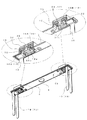
図1は、非水電解質二次電池を示す。この非水電解質二次電池は、図2に示すように、電池容器1内に発電要素2を収容し、蓋体3で封止したものである。ここでは、電池容器1と蓋体3とで外装体を構成している。
FIG. 1 shows a non-aqueous electrolyte secondary battery. As shown in FIG. 2, the non-aqueous electrolyte secondary battery is one in which a
電池容器1は、上面が開口する直方体形状で、アルミニウムやアルミニウム合金等で構成されている。
The
発電要素2は、詳細については図示しないが、従来同様、銅箔からなる負極4と、アルミニウム箔からなる正極5との間に、多孔性の樹脂フィルムからなるセパレータ6を配置したものである。これらはいずれも帯状で、セパレータ6に対して負極4と正極5とを幅方向の反対側にそれぞれ位置をずらせた状態で、前記電池容器1に収容可能となるように扁平状に巻回されている。後述するように、クリップ7を介して、負極4には負極集電体18が接続され、正極5には正極集電体19が接続されている。
Although not shown in detail for the power generating
蓋体3は、図3から図6に示すように、平面視矩形状の長尺な金属製の板状で、中央部には上面側から段付きとなる略楕円形状の開口部8が形成され、そこにはゴム製の安全弁9が装着されている。安全弁9には、略H字状の薄肉部が形成され、内圧が異常に上昇した場合に薄肉部が裂けて減圧できるようになっている。
As shown in FIGS. 3 to 6, the
蓋体3の一端側には、小径の注液孔10が形成され、注液後に栓体11によって閉鎖されるようになっている。
A small-diameter
蓋体3の両端部下面には、上方に向かって膨出する平面視略矩形状の係合受部12がそれぞれ形成され、各係合受部12では、下面側の係合凹部12aの一辺を除く周囲には浅めのガイド凹部12bがそれぞれ形成されている。また、係合凹部12aを構成する天井面の中心部分には貫通孔12cがそれぞれ形成されている。係合受部12及びガイド凹部12bには、集電体13及び外部端子14が上パッキン15及び下パッキン16を介してそれぞれ取り付けられるようになっている。
An
また、蓋体3には、各係合受部12の内側近傍に、幅方向の2箇所から上方に向かって突出する係止突部17がそれぞれ形成されている。各係止突部17は、有底筒状で、蓋体3をプレス加工する際、同時に形成される。各係止突部17には、後述する上パッキン15が係止され、回転方向の位置決めを行う。
The
集電体13は、銅製の負極集電体18と、アルミニウム製の正極集電体19とからなる。これら集電体13はいずれも、長尺な金属製板材をプレス加工することにより、接続受部20と、その両側部からそれぞれ延びる脚部21とを形成されている。接続受部20は、前記蓋体3の凹部内に配置される嵌合部22と、これに続く台座部23とで構成されている。嵌合部22は、平面状で、中央部分に貫通孔22aが形成され、周縁は台座部23に連続する一辺を除いて直交する方向に延在するガイド縁部24が形成され、台座部23側はガイド縁部24よりもさらに延在する連続部25となって台座部23に至っている。このようなガイド縁部24及び連続部25によって集電体13の接続受部20の剛性が十分に高められている。
The
脚部21は、台座部23の両側縁部から直交する方向に延び、発電要素2の両側面に沿って配置される。そして、脚部21は発電要素2の正極5又は負極4に、クリップ7を介して接続され、クリップ7が電池容器1の対向する内面間に挟持された状態となって位置ずれが防止される。
The
外部端子14は、負極外部端子28と正極外部端子29とからなり、平板部30と、その下面中央部から下方に向かって延びる軸部31とで構成されている。平板部30の表面(露出面)には、図示しないバスバーが溶接により接続される。
The
負極外部端子28は、図7に示すように、平面視矩形状のアルミニウム製の板状体32と、銅製のリベット33とによって形成することができる。すなわち、板状体32の中央部分に形成した貫通孔32aに、リベット33の軸部33aを挿通し、プレス加工で鍔部33bを貫通孔32aに圧入する。板状体32の貫通孔32aの内径寸法は、リベット33の軸部33aの外径寸法よりも若干大きいだけであり、鍔部33bの外径寸法よりも十分に小さい。したがって、圧入により、鍔部33bが貫通孔32aを押し広げて圧着状態となるほか、押し広げられた部分は軸部33aに圧着し、両者は一体化される。また、リベット33の軸部33aの先端面中央部には円形の凹部33cが形成されている。そして、後述するようにして、軸部33aを、上パッキン15、蓋体3の係合受部12、下パッキン16、及び、負極集電体18の各貫通孔に挿通させた後、これらを挟み込むようにして、前記凹部33cを押し広げることによりカシメ固定される。
As shown in FIG. 7, the negative electrode
上パッキン15は、平面視矩形の枠体を隔壁36によって、上方側の端子保持凹部37と、下方側の装着凹部38とに区画した合成樹脂製のもので、その下方開口縁部を構成する一辺がさらに側方へと延びる舌片39となっている。隔壁36の中央部分には天井面から下方側に延びる筒状部36aが形成されている。筒状部36aは、係合受部12の貫通孔12cを挿通し、下パッキン16の貫通孔40aに嵌合する。舌片39には2箇所に係止孔39aが形成され、蓋体3の係止突部17が挿通している。上パッキン15は、平面視矩形状に形成した蓋体3の係合受部12に沿っており、係合受部12に載置しただけで、回転方向の位置ずれが防止される。しかも、係止孔39aに係止突部17を挿通することにより、確実に回転方向の位置ずれが防止される。
The
下パッキン16は、平面視矩形の板状で、中央部分に貫通孔16aが形成されたゴム製のものである。下パッキン16は、負極側と正極側とで形状が若干相違している。
The
負極側下パッキン16Aでは、蓋体3の係合受部12に形成した係合凹部12a内に配置される膨出部40と、この膨出部40に連続する平坦部41とで構成されている。膨出部40は、係合受部12の係合凹部12aの一辺側を除く部分の内面に沿った形状をしており、中央部分には貫通孔40aが形成されている。平坦部41は、係合受部12のガイド凹部12bに配置される。負極側下パッキン16Aは、蓋体3の係合受部12を構成する係合凹部12aに対して下方側から配置され、蓋体3と負極外部端子28との間に挟持される。そして、この挟持状態で、負極外部端子28と蓋体3との絶縁を図り、かつ、前記上パッキン15と共に蓋体3の係合受部12に形成した貫通孔12cの封止を図る。
The negative side lower packing 16 </ b> A includes a bulging
一方、正極側下パッキン16Bは平板状であり、中央部分に貫通孔16aが形成され、係合受部12を構成する係合凹部12a内に配置される。正極側下パッキン16Bは、前記上パッキン15と共に蓋体3の係合受部12に形成した貫通孔12cの封止を図る。
On the other hand, the positive side lower packing 16 </ b> B has a flat plate shape, and a through hole 16 a is formed in the center portion, and is disposed in the engagement concave portion 12 a constituting the
前記構成の電池によれば、上パッキン15の装着凹部38を、蓋体3の係合受部12に載置するだけで、回転方向の位置ずれを防止することができる。したがって、外部端子14の軸部31を、上パッキン15、蓋体3、下パッキン16、及び、集電体13の各貫通孔に挿通して加締固定する際、上パッキン15が位置ずれすることがない。このため、これら一連の組立作業の作業性を向上させることが可能となる。
According to the battery having the above configuration, the displacement in the rotational direction can be prevented only by mounting the mounting
なお、本発明は、前記実施形態に記載された構成に限定されるものではなく、種々の変更が可能である。
例えば、前記上パッキン15は、平面視矩形状に限らず、三角形や、五角形以上の多角形や、楕円形等、円形以外の平面視で種々の形状とすることができる。要は、上パッキン15を装着した際、回転方向の位置ずれを防止可能な構成であればよい。場合によっては、蓋体3の係合受部12の形状と合致していなくてもよい。
また、前記電池容器1の形状は、直方体形状としたが、円筒状等、他の形状であっても、前記構成の蓋体3の係合受部12及び上パッキン15を採用することが可能である。
In addition, this invention is not limited to the structure described in the said embodiment, A various change is possible.
For example, the
Moreover, although the shape of the
本発明に係る電池の外部端子14の構造は、リチウムイオン電池のほか、鉛蓄電池等、種々の電池に採用することができる。
The structure of the
1…電池容器
2…発電要素
3…蓋体
4…負極
5…正極
6…セパレータ
7…クリップ
8…開口部
9…安全弁
10…注液孔
11…栓体
12…係合受部
12a…係合凹部
12b…ガイド凹部
12c…貫通孔
13…集電体
14…外部端子
15…上パッキン(外側パッキン)
16…下パッキン(内側パッキン)
16a…貫通孔
16A…負極側下パッキン
16B…正極側下パッキン
17…係止突部
18…負極集電体
19…正極集電体
20…接続受部
21…脚部
22…嵌合部
22a…貫通孔
23…台座部
24…ガイド縁部
25…連続部
28…負極外部端子
29…正極外部端子
30…平板部
31…軸部
32…板状体
32a…貫通孔
33…リベット
33a…軸部
33b…鍔部
34…板状体
34a…凹部
35…リベット
35a…鍔部
35b…軸部
36…隔壁
36a…貫通孔
37…端子保持凹部
38…装着凹部
39…舌片
39a…係止孔
40…膨出部
41…平坦部
DESCRIPTION OF
16 ... Lower packing (inner packing)
16a ... Through
Claims (2)
前記蓋体には、外側に向かって突出し、平面視が円形以外の形状である係合受部が形成され、
前記外側パッキンは、隔壁を挟んで一方側に形成され、前記係合受部に装着される装着凹部と、前記隔壁を挟んで他方側に形成され、前記外部端子が配置される端子保持凹部とが、平面視で重なった位置に形成されたことを特徴とする電池。 A battery container having an opening on one surface; a power generation element housed in the battery container; and a lid for closing the opening; and an external terminal exposed to the outside on the outer surface of the lid. A battery arranged via an outer packing,
The lid is formed with an engagement receiving portion that protrudes outward and has a shape other than circular in plan view.
The outer packing is formed on one side across the partition and is mounted on the engagement receiving portion, and the terminal holding recess is formed on the other side across the partition and the external terminal is disposed. Is formed at a position overlapping in plan view .
一端部が前記外側パッキン、前記蓋体、前記内側パッキン、及び前記集電体を貫通してかしめられ、他端部に鍔部を有するリベットを備える、請求項1に記載の電池。 The lid is attached with the current collector connected to the external terminal and the power generation element via the outer packing and the inner packing, respectively.
The battery according to claim 1, further comprising a rivet having one end portion caulked through the outer packing, the lid, the inner packing, and the current collector and having a flange portion at the other end portion.
Priority Applications (1)
| Application Number | Priority Date | Filing Date | Title |
|---|---|---|---|
| JP2015028941A JP6032302B2 (en) | 2015-02-17 | 2015-02-17 | battery |
Applications Claiming Priority (1)
| Application Number | Priority Date | Filing Date | Title |
|---|---|---|---|
| JP2015028941A JP6032302B2 (en) | 2015-02-17 | 2015-02-17 | battery |
Related Parent Applications (1)
| Application Number | Title | Priority Date | Filing Date |
|---|---|---|---|
| JP2010276204A Division JP5699578B2 (en) | 2010-12-10 | 2010-12-10 | battery |
Publications (2)
| Publication Number | Publication Date |
|---|---|
| JP2015118947A JP2015118947A (en) | 2015-06-25 |
| JP6032302B2 true JP6032302B2 (en) | 2016-11-24 |
Family
ID=53531471
Family Applications (1)
| Application Number | Title | Priority Date | Filing Date |
|---|---|---|---|
| JP2015028941A Active JP6032302B2 (en) | 2015-02-17 | 2015-02-17 | battery |
Country Status (1)
| Country | Link |
|---|---|
| JP (1) | JP6032302B2 (en) |
Families Citing this family (1)
| Publication number | Priority date | Publication date | Assignee | Title |
|---|---|---|---|---|
| JP6780419B2 (en) * | 2016-09-30 | 2020-11-04 | 株式会社Gsユアサ | Power storage element |
Family Cites Families (3)
| Publication number | Priority date | Publication date | Assignee | Title |
|---|---|---|---|---|
| JP3937427B2 (en) * | 2001-11-20 | 2007-06-27 | 株式会社ジーエス・ユアサコーポレーション | Battery manufacturing method |
| JP2009087722A (en) * | 2007-09-28 | 2009-04-23 | Toshiba Corp | Battery and battery pack |
| JP5418809B2 (en) * | 2008-10-16 | 2014-02-19 | 株式会社Gsユアサ | Battery and manufacturing method thereof |
-
2015
- 2015-02-17 JP JP2015028941A patent/JP6032302B2/en active Active
Also Published As
| Publication number | Publication date |
|---|---|
| JP2015118947A (en) | 2015-06-25 |
Similar Documents
| Publication | Publication Date | Title |
|---|---|---|
| JP5699578B2 (en) | battery | |
| KR101921157B1 (en) | Storage element and terminal fabricating method | |
| JP5987465B2 (en) | Storage element and method for manufacturing the same | |
| JP5919777B2 (en) | Electricity storage element | |
| JP5625959B2 (en) | battery | |
| JP6011344B2 (en) | Electricity storage element | |
| JP5994640B2 (en) | Electricity storage element | |
| JP6476710B2 (en) | Storage element | |
| JP5742260B2 (en) | battery | |
| JP6693042B2 (en) | Storage element | |
| JP6160081B2 (en) | Storage element and method for manufacturing the same | |
| JP5884872B2 (en) | battery | |
| JP6032302B2 (en) | battery | |
| JP6554842B2 (en) | Electricity storage element | |
| JP2018098130A (en) | Power storage element | |
| JP6413976B2 (en) | battery | |
| JP6160049B2 (en) | Power storage device manufacturing method and power storage device | |
| JP2019091709A (en) | Power storage element | |
| JP2018041646A (en) | Power storage element and method of manufacturing power storage element |
Legal Events
| Date | Code | Title | Description |
|---|---|---|---|
| A131 | Notification of reasons for refusal |
Free format text: JAPANESE INTERMEDIATE CODE: A131 Effective date: 20160315 |
|
| A521 | Request for written amendment filed |
Free format text: JAPANESE INTERMEDIATE CODE: A523 Effective date: 20160516 |
|
| TRDD | Decision of grant or rejection written | ||
| A01 | Written decision to grant a patent or to grant a registration (utility model) |
Free format text: JAPANESE INTERMEDIATE CODE: A01 Effective date: 20160927 |
|
| A61 | First payment of annual fees (during grant procedure) |
Free format text: JAPANESE INTERMEDIATE CODE: A61 Effective date: 20161010 |
|
| R150 | Certificate of patent or registration of utility model |
Ref document number: 6032302 Country of ref document: JP Free format text: JAPANESE INTERMEDIATE CODE: R150 |