EP2463868A1 - Soft magnetic amorphous alloy ribbon, method for producing same, and magnetic core using same - Google Patents
Soft magnetic amorphous alloy ribbon, method for producing same, and magnetic core using same Download PDFInfo
- Publication number
- EP2463868A1 EP2463868A1 EP10815497A EP10815497A EP2463868A1 EP 2463868 A1 EP2463868 A1 EP 2463868A1 EP 10815497 A EP10815497 A EP 10815497A EP 10815497 A EP10815497 A EP 10815497A EP 2463868 A1 EP2463868 A1 EP 2463868A1
- Authority
- EP
- European Patent Office
- Prior art keywords
- magnetic
- amorphous alloy
- soft
- alloy ribbon
- recesses
- Prior art date
- Legal status (The legal status is an assumption and is not a legal conclusion. Google has not performed a legal analysis and makes no representation as to the accuracy of the status listed.)
- Granted
Links
- 229910000808 amorphous metal alloy Inorganic materials 0.000 title claims abstract description 117
- 238000004519 manufacturing process Methods 0.000 title claims description 11
- XEEYBQQBJWHFJM-UHFFFAOYSA-N Iron Chemical compound [Fe] XEEYBQQBJWHFJM-UHFFFAOYSA-N 0.000 claims abstract description 129
- 229910052742 iron Inorganic materials 0.000 claims abstract description 61
- 229910045601 alloy Inorganic materials 0.000 claims abstract description 38
- 239000000956 alloy Substances 0.000 claims abstract description 38
- 238000000034 method Methods 0.000 claims abstract description 20
- 238000010791 quenching Methods 0.000 claims abstract description 9
- 230000000171 quenching effect Effects 0.000 claims abstract description 9
- 239000000835 fiber Substances 0.000 claims description 19
- 230000005381 magnetic domain Effects 0.000 claims description 14
- 229910008423 Si—B Inorganic materials 0.000 claims description 7
- 230000001678 irradiating effect Effects 0.000 claims description 5
- 238000010030 laminating Methods 0.000 claims description 5
- 238000004804 winding Methods 0.000 claims description 5
- 238000003475 lamination Methods 0.000 description 18
- 230000007423 decrease Effects 0.000 description 12
- 230000003247 decreasing effect Effects 0.000 description 10
- 230000000694 effects Effects 0.000 description 7
- 238000005096 rolling process Methods 0.000 description 7
- 239000012535 impurity Substances 0.000 description 6
- 239000000203 mixture Substances 0.000 description 6
- 230000015572 biosynthetic process Effects 0.000 description 5
- 230000005415 magnetization Effects 0.000 description 5
- 238000000137 annealing Methods 0.000 description 4
- 238000009826 distribution Methods 0.000 description 4
- 230000002547 anomalous effect Effects 0.000 description 3
- 230000000052 comparative effect Effects 0.000 description 3
- 239000013078 crystal Substances 0.000 description 3
- 230000004907 flux Effects 0.000 description 3
- 238000010438 heat treatment Methods 0.000 description 3
- 229910000521 B alloy Inorganic materials 0.000 description 2
- 229910001339 C alloy Inorganic materials 0.000 description 2
- 229910001096 P alloy Inorganic materials 0.000 description 2
- VYPSYNLAJGMNEJ-UHFFFAOYSA-N Silicium dioxide Chemical compound O=[Si]=O VYPSYNLAJGMNEJ-UHFFFAOYSA-N 0.000 description 2
- 230000006866 deterioration Effects 0.000 description 2
- 239000007788 liquid Substances 0.000 description 2
- 230000008018 melting Effects 0.000 description 2
- 238000002844 melting Methods 0.000 description 2
- 238000007712 rapid solidification Methods 0.000 description 2
- 229910052782 aluminium Inorganic materials 0.000 description 1
- PNEYBMLMFCGWSK-UHFFFAOYSA-N aluminium oxide Inorganic materials [O-2].[O-2].[O-2].[Al+3].[Al+3] PNEYBMLMFCGWSK-UHFFFAOYSA-N 0.000 description 1
- 230000005540 biological transmission Effects 0.000 description 1
- 229910052804 chromium Inorganic materials 0.000 description 1
- 229910052681 coesite Inorganic materials 0.000 description 1
- 229910052802 copper Inorganic materials 0.000 description 1
- 229910052593 corundum Inorganic materials 0.000 description 1
- 229910052906 cristobalite Inorganic materials 0.000 description 1
- 238000002425 crystallisation Methods 0.000 description 1
- 230000008025 crystallization Effects 0.000 description 1
- 238000005520 cutting process Methods 0.000 description 1
- 238000006073 displacement reaction Methods 0.000 description 1
- -1 etc. Inorganic materials 0.000 description 1
- 229910052733 gallium Inorganic materials 0.000 description 1
- 229910052732 germanium Inorganic materials 0.000 description 1
- 229910052737 gold Inorganic materials 0.000 description 1
- 229910052735 hafnium Inorganic materials 0.000 description 1
- 229910052738 indium Inorganic materials 0.000 description 1
- CPLXHLVBOLITMK-UHFFFAOYSA-N magnesium oxide Inorganic materials [Mg]=O CPLXHLVBOLITMK-UHFFFAOYSA-N 0.000 description 1
- 239000000696 magnetic material Substances 0.000 description 1
- 229910052748 manganese Inorganic materials 0.000 description 1
- 238000005259 measurement Methods 0.000 description 1
- 239000000155 melt Substances 0.000 description 1
- 229910052750 molybdenum Inorganic materials 0.000 description 1
- 229910052759 nickel Inorganic materials 0.000 description 1
- 229910052758 niobium Inorganic materials 0.000 description 1
- 230000003287 optical effect Effects 0.000 description 1
- 229910052702 rhenium Inorganic materials 0.000 description 1
- 229910052707 ruthenium Inorganic materials 0.000 description 1
- 229920006395 saturated elastomer Polymers 0.000 description 1
- 238000006748 scratching Methods 0.000 description 1
- 230000002393 scratching effect Effects 0.000 description 1
- 239000000377 silicon dioxide Substances 0.000 description 1
- 229910052709 silver Inorganic materials 0.000 description 1
- 238000009751 slip forming Methods 0.000 description 1
- 229910052682 stishovite Inorganic materials 0.000 description 1
- 230000001629 suppression Effects 0.000 description 1
- 230000003746 surface roughness Effects 0.000 description 1
- 229910052715 tantalum Inorganic materials 0.000 description 1
- 229910052718 tin Inorganic materials 0.000 description 1
- 229910052719 titanium Inorganic materials 0.000 description 1
- 229910052905 tridymite Inorganic materials 0.000 description 1
- 229910052720 vanadium Inorganic materials 0.000 description 1
- 229910001845 yogo sapphire Inorganic materials 0.000 description 1
- 229910052725 zinc Inorganic materials 0.000 description 1
- 229910052726 zirconium Inorganic materials 0.000 description 1
Images


Classifications
-
- C—CHEMISTRY; METALLURGY
- C22—METALLURGY; FERROUS OR NON-FERROUS ALLOYS; TREATMENT OF ALLOYS OR NON-FERROUS METALS
- C22C—ALLOYS
- C22C38/00—Ferrous alloys, e.g. steel alloys
- C22C38/02—Ferrous alloys, e.g. steel alloys containing silicon
-
- C—CHEMISTRY; METALLURGY
- C22—METALLURGY; FERROUS OR NON-FERROUS ALLOYS; TREATMENT OF ALLOYS OR NON-FERROUS METALS
- C22C—ALLOYS
- C22C45/00—Amorphous alloys
- C22C45/02—Amorphous alloys with iron as the major constituent
-
- H—ELECTRICITY
- H01—ELECTRIC ELEMENTS
- H01F—MAGNETS; INDUCTANCES; TRANSFORMERS; SELECTION OF MATERIALS FOR THEIR MAGNETIC PROPERTIES
- H01F1/00—Magnets or magnetic bodies characterised by the magnetic materials therefor; Selection of materials for their magnetic properties
- H01F1/01—Magnets or magnetic bodies characterised by the magnetic materials therefor; Selection of materials for their magnetic properties of inorganic materials
- H01F1/03—Magnets or magnetic bodies characterised by the magnetic materials therefor; Selection of materials for their magnetic properties of inorganic materials characterised by their coercivity
- H01F1/12—Magnets or magnetic bodies characterised by the magnetic materials therefor; Selection of materials for their magnetic properties of inorganic materials characterised by their coercivity of soft-magnetic materials
- H01F1/14—Magnets or magnetic bodies characterised by the magnetic materials therefor; Selection of materials for their magnetic properties of inorganic materials characterised by their coercivity of soft-magnetic materials metals or alloys
- H01F1/147—Alloys characterised by their composition
- H01F1/153—Amorphous metallic alloys, e.g. glassy metals
- H01F1/15341—Preparation processes therefor
-
- H—ELECTRICITY
- H01—ELECTRIC ELEMENTS
- H01F—MAGNETS; INDUCTANCES; TRANSFORMERS; SELECTION OF MATERIALS FOR THEIR MAGNETIC PROPERTIES
- H01F41/00—Apparatus or processes specially adapted for manufacturing or assembling magnets, inductances or transformers; Apparatus or processes specially adapted for manufacturing materials characterised by their magnetic properties
- H01F41/02—Apparatus or processes specially adapted for manufacturing or assembling magnets, inductances or transformers; Apparatus or processes specially adapted for manufacturing materials characterised by their magnetic properties for manufacturing cores, coils, or magnets
- H01F41/0206—Manufacturing of magnetic cores by mechanical means
- H01F41/0213—Manufacturing of magnetic circuits made from strip(s) or ribbon(s)
- H01F41/0226—Manufacturing of magnetic circuits made from strip(s) or ribbon(s) from amorphous ribbons
-
- Y—GENERAL TAGGING OF NEW TECHNOLOGICAL DEVELOPMENTS; GENERAL TAGGING OF CROSS-SECTIONAL TECHNOLOGIES SPANNING OVER SEVERAL SECTIONS OF THE IPC; TECHNICAL SUBJECTS COVERED BY FORMER USPC CROSS-REFERENCE ART COLLECTIONS [XRACs] AND DIGESTS
- Y10—TECHNICAL SUBJECTS COVERED BY FORMER USPC
- Y10T—TECHNICAL SUBJECTS COVERED BY FORMER US CLASSIFICATION
- Y10T29/00—Metal working
- Y10T29/49—Method of mechanical manufacture
- Y10T29/49002—Electrical device making
- Y10T29/4902—Electromagnet, transformer or inductor
- Y10T29/49075—Electromagnet, transformer or inductor including permanent magnet or core
- Y10T29/49078—Laminated
-
- Y—GENERAL TAGGING OF NEW TECHNOLOGICAL DEVELOPMENTS; GENERAL TAGGING OF CROSS-SECTIONAL TECHNOLOGIES SPANNING OVER SEVERAL SECTIONS OF THE IPC; TECHNICAL SUBJECTS COVERED BY FORMER USPC CROSS-REFERENCE ART COLLECTIONS [XRACs] AND DIGESTS
- Y10—TECHNICAL SUBJECTS COVERED BY FORMER USPC
- Y10T—TECHNICAL SUBJECTS COVERED BY FORMER US CLASSIFICATION
- Y10T428/00—Stock material or miscellaneous articles
- Y10T428/12—All metal or with adjacent metals
- Y10T428/12389—All metal or with adjacent metals having variation in thickness
Definitions
- the present invention relates to a soft-magnetic, amorphous alloy ribbon with low loss and apparent power and a high lamination factor and suitable for distribution transformers, high-frequency transformers, saturable reactors, magnetic switches, etc., its production method, and a magnetic core constituted by such soft-magnetic, amorphous alloy ribbon.
- Soft-magnetic, Fe- or Co-based, amorphous alloys produced by liquid quenching methods such as a single roll method, etc. are free from magnetocrystalline anisotropy because of no crystal grains, having small magnetic hysteresis loss, low coercivity and excellent soft magnetic properties. Because of these properties, amorphous alloy ribbons are used in magnetic cores for various transformers, choke coils, saturable reactors and magnetic switches, magnetic sensors, etc. Particularly, Fe-based, amorphous alloy ribbons have relatively high saturation magnetic flux densities Bs, low coercivity, and low loss, gathering much attention as energy-saving, soft-magnetic materials. Among the Fe-based, amorphous alloy ribbons, amorphous Fe-Si-B alloy ribbons having excellent thermal stability are widely used in transformer cores (see, for example, JP 2006-45662 A ).
- amorphous Fe-Si-B alloys have low coercivity and small magnetic hysteresis loss, it is known that their eddy current loss (iron loss - hysteresis loss) in a broad sense is larger than a classical eddy current loss determined under the assumption of uniform magnetization by tens of times to about 100 times.
- the difference between the broad-sense eddy current loss and the classical eddy current loss is called anomalous eddy current loss or excess loss, which is mainly caused by non-uniform magnetization change.
- Known as methods for reducing anomalous eddy current loss in amorphous alloy ribbons are a method of mechanically scratching a surface of an amorphous alloy ribbon ( JP 62-49964 B ), and a laser-scribing method of irradiating a surface of an amorphous alloy ribbon with laser beams to cause local melting and rapid solidification, thereby dividing magnetic domains ( JP 3-32886 B , JP 3-32888 B and JP 2-53935 B ).
- an amorphous alloy ribbon surface is melted locally and instantaneously by the irradiation of laser pulses in a transverse direction, and then rapidly solidified to form substantially circular recesses in lines.
- Each recess has a diameter of 0.5 mm or less, particularly 200-250 ⁇ m when the recesses are formed before annealing, and 50-100 ⁇ m when they are formed after annealing.
- the recesses have an average interval of 1-20 mm. In a diameter range of 50-250 ⁇ m, the iron loss decreases as the diameter increases.
- Example 1 of JP 3-32886 B recesses having diameters of about 50-250 ⁇ m are formed with 5-mm intervals by a YAG laser on a 65- ⁇ m-thick, amorphous alloy ribbon.
- Molten alloy splashes are observed around recesses formed by the method of JP 3-32886 B . This appears to be due to the fact that to form recesses with large intervals on a relatively thick amorphous alloy ribbon, deep recesses are formed by a large irradiation energy density of laser beams. It has been found, however, that when deep recesses are formed at such a large irradiation energy density of laser beams that splashes are formed around the recesses, particularly a relatively thin amorphous alloy ribbon would suffer increase in apparent power (exciting VA) and decrease in a space factor despite the decreased iron loss. Increase in the apparent power of the amorphous alloy ribbon results in larger sound noise when used for distribution transformers, etc.
- the space factor has the same meaning as a lamination factor LF, smaller LF providing larger ribbon-laminated cores.
- Increase in the apparent power and decrease in the lamination factor have more serious problems on thinner amorphous alloy ribbons, because thinner amorphous alloy ribbons are more influenced by laser-scribed surface conditions than thicker amorphous alloy ribbons.
- the method of JP 3-32888 B for dividing magnetic domains comprises the steps of irradiating an amorphous alloy ribbon with laser pulses having a beam diameter of 0.5 mm or less with an energy density of 0.02-1.0 J/mm 2 per one pulse in a transverse direction, so that an amorphous alloy ribbon surface is locally and instantaneously melted and rapidly solidified, thereby forming substantially circular recesses at a line density of 10% or more, and annealing the ribbon.
- This method is an improvement of the method of JP 3-32886 B , optimizing the distribution density of recesses and the timing of annealing to improve iron loss and exciting properties.
- Example 1 of JP 3-32888 B a 65- ⁇ m-thick, amorphous alloy ribbon is irradiated with laser pulses having a beam diameter of 0.2 mm and an energy density of about 0.3 J/mm 2 , which is supplied from a YAG laser, to form lines of recesses at line density of about 70%.
- molten alloy splashes are observed around recesses shown in JP 3-32888 B . This seems to be due to the fact that deep recesses are formed by a large irradiation energy density of laser beams. As a result, the apparent power increases despite the decreased iron loss.
- JP 3-32888 B describes an energy density of 0.02-1.0 J/mm 2 per one pulse.
- laser pulses having as low energy as near 0.02 J/mm 2 are projected to an amorphous alloy ribbon as thick as 65 ⁇ m, the resultant recesses are not fully deep relative to the thickness of the amorphous alloy ribbon, failing to obtain a sufficient iron loss-reducing effect.
- JP 2-53935 B The method of JP 2-53935 B is the same as those described in JP 3-32886 B and JP 3-32888 B , in that an amorphous alloy ribbon is irradiated with laser beams in a transverse direction to melt the surface locally.
- the former is different from the latter in that molten portions are crystallized regions.
- the crystallized regions are formed by the scanning of laser beams, etc., a ratio d/D of their depth d to the thickness D of the amorphous alloy ribbon being 0.1 or more, and the percentage of the crystallized regions being 8% or less by volume based on the entire ribbon.
- the molten portions are crystallized regions, the iron loss is not sufficiently reduced.
- an object of the present invention is to provide a soft-magnetic, amorphous alloy ribbon having low iron loss and apparent power as well as a high lamination factor, its production method, and a magnetic core constituted by such soft-magnetic, amorphous alloy ribbon.
- the soft-magnetic, amorphous alloy ribbon of the present invention is formed by a rapid quenching method, and has transverse lines of recesses formed on its surface by laser beams with predetermined longitudinal intervals, with a doughnut-shaped projection formed around each recess; the doughnut-shaped projections having smooth surfaces substantially free from splashes of the alloy melted by the irradiation of laser beams, and a height t 2 of 2 ⁇ m or less; and a ratio t 1 /T of the depth t 1 of the recesses to the thickness T of the ribbon being in a range of 0.025-0.18, thereby having low iron loss and low apparent power.
- the openings of the recesses are preferably substantially circular.
- the height t 2 of the doughnut-shaped projections is preferably 0.5-2 ⁇ m, more preferably 0.5-1.8 ⁇ m.
- a ratio t 1 /T of the depth t 1 of the recesses to the thickness T of the ribbon is preferably in a range of 0.03-0.15.
- the thickness T of the ribbon is preferably 30 ⁇ m or less.
- the t 1 /T ratio can be made small, suppressing increase in the apparent power.
- a ratio t/T of the total t of the depth t 1 of the recesses and the height t 2 of the doughnut-shaped projections to the thickness T of the ribbon is preferably 0.2 or less, more preferably 0.16 or less.
- the soft-magnetic, amorphous alloy ribbon is preferably made of an Fe-Si-B alloy.
- a surface of the amorphous alloy ribbon, which is irradiated with laser beams preferably has reflectance of 15-80% at a wavelength ⁇ of 1000 nm.
- the term "reflectance” used herein means a ratio of laser beams reflected in an incident direction to incident laser beams, when the laser beams are vertically projected to the alloy ribbon surface. Accordingly, the reflectance of 10% means that 10% of laser beams are reflected in the incident direction, and that the total of laser beams diffuse-reflected to other directions and those absorbed by the alloy ribbon is 90%. With reflectance in this range, the irradiation energy density of laser beams is not excessively large or small, easily forming recesses surrounded by doughnut-shaped projections having smooth surfaces substantially free from molten alloy splashes.
- the method of the present invention for producing a soft-magnetic, amorphous alloy ribbon having low iron loss and low apparent power comprises irradiating a surface of a soft-magnetic, amorphous alloy ribbon produced by a rapid quenching method with laser beam pulses successively in a transverse direction with predetermined longitudinal intervals, to form transverse lines of recesses; the irradiation energy density of the laser beam pulses being controlled, such that (a) a doughnut-shaped projection is formed around each recess, that (b) the doughnut-shaped projections have substantially no molten alloy splashes to have smooth surfaces, that (c) the doughnut-shaped projections have a height t 2 of 2 ⁇ m or less, and that (d) a ratio t 1 /T of the depth t 1 of the recesses to the thickness T of the ribbon is in a range of 0.025-0.18, thereby dividing magnetic domains in the amorphous alloy while suppressing increase in the apparent power.
- the amorphous alloy ribbon is preferably irradiated with the laser beam pulses passing through a galvanometer scanner or a polygon scanner and an f ⁇ lens.
- the laser beam pulses are preferably generated by a fiber laser. Because the fiber laser capable of highly focusing to a small spot is resistant to thermal influence, it can suppress the formation of molten alloy splashes around the recesses, thereby forming doughnut-shaped projections having smooth surfaces. Also, because of a large depth of focus, high-precision depth control can be conducted by the fiber laser, thereby forming shallow recesses on thin alloy ribbons.
- t/T ratio of 0.2 or less, it is preferable to adjust the depth of focus of the f ⁇ lens, or to control the irradiation energy density of laser beams per one pulse.
- the irradiation energy density of the laser beam pulses is preferably 5 J/cm 2 or less, preferably 2-5 J/cm 2 more, most preferably 2.5-4 J/cm 2 .
- the magnetic core of the present invention is obtained by laminating or winding the above soft-magnetic, amorphous alloy ribbon. This magnetic core has low iron loss and a high lamination factor.
- the soft-magnetic, amorphous alloy ribbon is preferably provided with the above recesses, and then heat-treated in a magnetic field oriented in a magnetic path direction. This reduces core loss at low frequencies, and apparent power contributing to the generation of sound noise.
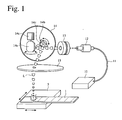
- Fig. 1 is a schematic view showing one example of laser-beam-radiating apparatuses used in the production method of the present invention.
- Fig. 2(a) is a schematic cross-sectional view showing recesses and annular projections formed on a soft-magnetic, amorphous alloy ribbon.
- Fig. 2(b) is a schematic plan view showing recesses and annular projections formed on a soft-magnetic, amorphous alloy ribbon.
- Fig. 3 is a schematic plan view showing the arrangement of recesses formed on a soft-magnetic, amorphous alloy ribbon.
- Fig. 4(a) is an electron photomicrograph (magnification: 60 times) showing one example of recess lines formed on a soft-magnetic, amorphous alloy ribbon.
- Fig. 4(b) is an enlarged electron photomicrograph (magnification: 240 times) showing one of the recesses shown in Fig. 4(a) .
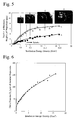
- Fig. 5 is a graph showing the relation between the depth t 1 of recesses and the height t 2 of annular projections and the irradiation energy density of laser beams, together with electron photomicrographs of recesses and annular projections formed on the soft-magnetic, amorphous alloy ribbon.
- Fig. 6 is a graph showing the relation between the outer diameter D 2 of annular projections on the soft-magnetic, amorphous alloy ribbon and the irradiation energy density of laser beams.
- Fig. 7 is a graph showing the relation between the apparent power S of a soft-magnetic, amorphous alloy ribbon at 50 Hz and 1.3 T and the height t 2 of annular projections.
- Fig. 8 is a graph showing the relation between the iron loss P of a soft-magnetic, amorphous alloy ribbon at 50 Hz and 1.3 T and the height t 2 of annular projections.
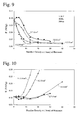
- Fig. 9 is a graph showing the relation between the number density n of recesses and iron loss P in a soft-magnetic, amorphous alloy ribbon.
- Fig. 10 is a graph showing the relation between the number density n of recesses and apparent power S in a soft-magnetic, amorphous alloy ribbon.
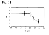
- Fig. 11 is a graph showing the relation between a lamination factor LF and the height t 2 of annular projections in a soft-magnetic, amorphous alloy ribbon.
- Amorphous alloys usable in the present invention include Fe-B alloys, Fe-Si-B alloys, Fe-Si-B-C alloys, Fe-Si-B-P alloys, Fe-Si-B-C-P alloys, Fe-P-B alloys, etc., and alloys based on Fe, Si and B are preferable because they are resistant to embrittlement by laser beam irradiation, and easily subject to working such as cutting, etc.
- the amorphous Fe-Si-B alloy preferably has a composition comprising 1-15 atomic % of Si and 8-20 atomic % of B, the balance being substantially Fe and inevitable impurities.
- the Fe-Si-B-C alloy preferably has a composition comprising 1-15 atomic % of Si, 8-20 atomic % of B, and 3 atomic % or less of C, the balance being Fe and inevitable impurities.
- the inclusion of 10 atomic % or less of Si and 17 atomic % or less of B provides high Bs, and drastically reduces iron loss due to the irradiation of laser beams, making the production of amorphous alloys easy.
- the amorphous alloy may contain at least one selected from the group consisting of Co, Ni, Mn, Cr, V, Mo, Nb, Ta, Hf, Zr, Ti, Cu, Au, Ag, Sn, Ge, Re, Ru, Zn, In and Ga, in a proportion of 5 atomic % or less in total to Fe.
- the inevitable impurities are S, O, N, Al, etc.
- Amorphous alloy ribbons are produced preferably by a liquid quenching method, such as a single roll method or a double roll method.
- the amorphous alloy ribbon which are irradiated with laser beams, preferably has a surface having reflectance R (%) of 15-80% at a wavelength ⁇ of 1000 nm.
- the reflectance R (%) is expressed by 100 x ⁇ r/ ⁇ , wherein ⁇ represents the quantity of luminous flux vertically projected to the ribbon surface, and ⁇ r represents the quantity of luminous flux reflected from the ribbon surface in the incident direction.
- ⁇ and ⁇ r are measured by a spectrometer (JASCO V-570 available from JASCO Corporation) at a wavelength of 1000 nm (close to the wavelength of laser beams used).
- the thickness T of the amorphous alloy ribbon is preferably 30 ⁇ m or less as described below.
- the width of the amorphous alloy ribbon is not restrictive, and an amorphous alloy ribbon as wide as about 25-220 mm can be subject to uniform laser scribing by a fiber laser described below.
- one or both surfaces of the amorphous alloy ribbon may be coated with an insulating layer of SiO 2 , Al 2 O 3 , MgO, etc.
- an insulating layer of SiO 2 , Al 2 O 3 , MgO, etc.
- a YAG laser, a CO 2 gas laser, a fiber laser, etc. may be used as an apparatus for generating laser beam pulses.
- a fiber laser capable of stably generating high-power, high-frequency laser beam pulses for a long period of time.
- laser beams introduced into a fiber are oscillated by diffraction gratings on both ends thereof by the principle of fiber Bragg grating (FBG).
- laser beams are excited in an elongated fiber, they are not subject to a thermal lens effect leading to their quality deterioration due to a temperature gradient occurring in the crystals. Further, because a fiber core is as thin as several microns, even high-power laser beams are conveyed in a single mode with a reduced beam diameter, resulting in high-energy-density laser beams. In addition, because of a large depth of focus, lines of recesses can be formed precisely on a ribbon as wide as 200 mm or more.
- the pulse width of the fiber laser is usually from about microseconds to about picoseconds, though it may be on the femtosecond level.
- the laser beams have wavelength of about 250-1100 nm, and they are mostly used in a wavelength of about 1000 nm.
- the beam diameter of the laser beams is preferably 10-300 ⁇ m, more preferably 20-100 ⁇ m, most preferably 30-90 ⁇ m.
- Fig. 1 shows one example of laser-beam-radiating apparatuses.
- This apparatus comprises a laser oscillator (fiber laser) 10, a collimator 12, a beam expander 13, a galvanometer scanner 14, and a f ⁇ lens 15.
- Laser beam pulses L (for example, wavelength: 1065 ⁇ m) generated by the laser oscillator 10 are transmitted via the fiber 11 to the collimator 12, in which they are made parallel.
- the diameters of parallel laser beams L are expanded by the beam expander 13.
- After passing through the galvanometer scanner 14, they are collected by the f ⁇ lens 15, and irradiated onto the amorphous alloy ribbon 1 placed on a table 5 movable in both X and Y directions.
- the galvanometer scanner 14 has mirrors 14a, 14b turning around the X and Y axes, each mirror 14a, 14b being moved by a motor 14c. With a combination of the mirrors 14a, 14b, the ribbon 1 is scanned with laser beam pulses L in a transverse direction with predetermined longitudinal intervals.
- a polygon scanner (not shown) comprising a polygon mirror at a tip of the motor may be used.
- the scanning direction of laser beams L should be inclined to the transverse direction with a predetermined angle.
- the irradiation of laser beams is preferably conducted while the amorphous alloy ribbon unwound from a reel is moving intermittently in a longitudinal direction, though it may be conducted before an amorphous alloy ribbon produced by a rapid quenching method is wound around a reel.
- the laser scribing is conducted preferably before the heat treatment. Because recesses formed on a soft-magnetic, amorphous alloy ribbon by the irradiation of laser beams are not crystallized, the ribbon has such good workability that it is easily cut and bent to produce magnetic cores.
- Fig. 2(a) schematically shows the cross section of a substantially circular recess 2 and a surrounding annular projection (rim) 3 formed on the soft-magnetic, amorphous alloy ribbon 1.
- substantially circular used herein means, as shown in Fig. 2(b) , that the contour of each recess 2 needs not to be a true circle, but may be a deformed circle or an ellipse.
- a ratio of a major axis Da to a minor axis Db, which represents the degree of deformation of the deformed circle or the ellipse, is preferably within 1.5.
- the diameter D 1 of the recess 2 is a diameter of the opening of the recess 2 at a level of a straight line 1a passing the surface of the ribbon 1
- the depth t 1 of the recess 2 is a distance between the straight line 1a and the bottom of the recess 2
- the outer diameter D 2 of the annular projection 3 is an outer diameter of the annular projection 3 at a level of the straight line 1a
- the height t 2 of the annular projection 3 is a distance between the straight line 1a and the apex of the annular projection 3
- the width W of the annular projection 3 is [(D 2 - D 1 )/2] determined at a level of the straight line 1a. Any of these parameters are expressed by average values determined from recesses 2 and annular projections 3 in plural (3 or more) transverse lines of recesses.
- the resultant recesses 2 and surrounding annular projections 3 are substantially in an amorphous state. Because this rapid solidification generates stress near the recesses 2, forming magnetic domains whose magnetization is oriented in the depth direction of the ribbon, it is presumed that the apparent power increases. Stress increases not only by the height of the annular projections 3, but also by melt splashes attached around the recesses 2. On the other hand, the division of magnetic domains by the recesses 2 reduces iron loss, resulting in reduced apparent power.
- annular projections having a doughnut shape (simply called “doughnut-shaped projections") having smooth surfaces substantially free from molten alloy splashes, with height t 2 limited to 2 ⁇ m or less, are formed around the recesses by controlling the irradiation energy of laser beams to the thickness T of the amorphous alloy ribbon.
- the term "smooth surfaces substantially free from splashes” used herein means, as shown in Fig. 2(b) , that annular projections 3 observed in an optical photomicrograph (50 times) have smooth inside and outside contours 3a, 3b without projections, with the same surface roughness between the annular projections 3 and other portions of the amorphous alloy ribbon 1.
- the “doughnut shape” has smooth surface and contour, unless otherwise mentioned. Accordingly, for example, when the inside and outside contours of annular projections 3 are ragged in recesses B, C, D as shown in Fig. 5 , the requirement of "smooth surfaces substantially free from splashes" is not met. By the above requirement, it is possible to reduce the iron loss while effectively suppressing increase in the apparent power.
- the height t 2 of the doughnut-shaped projections 3 is more preferably 1.8 ⁇ m or less, most preferably 0.3-1.8 ⁇ m.
- t 1 /T should be in a range of 0.025-0.18, preferably 0.03-0.15, more preferably 0.03-0.13.
- the thickness T of the amorphous alloy ribbon 1 is preferably 30 ⁇ m or less. When the thickness T of the amorphous alloy ribbon 1 is more than 30 ⁇ m, the value of t 1 is large for the same t 1 /T, resulting in larger apparent power.
- t/T is 0.2 or less, increase in the apparent power is suppressed.
- the ratio t/T is preferably 0.18 or less, more preferably 0.16 or less.
- the diameter D 1 of the recesses 2 is preferably 20-50 ⁇ m, more preferably 20-40 ⁇ m, most preferably 24-38 ⁇ m.
- the outer diameter D 2 of the doughnut-shaped projections 3 is preferably 100 ⁇ m or less, more preferably 80 ⁇ m or less, most preferably 76 ⁇ m or less.
- the lower limit of the outer diameter D 2 is preferably 30 ⁇ m.
- the longitudinal intervals of lines of recesses is generally 2-20 mm, for example, preferably 3-10 mm.
- recesses may be arranged with intervals, or adjacent recesses may be overlapped.
- the number density of recesses in the transverse lines is 2/mm to 25/mm, preferably 4/mm to 20/mm.
- Magnetic cores obtained by laminating or winding the soft-magnetic, amorphous alloy ribbons of the present invention have low iron loss with suppressed apparent power and high lamination factors LF.
- a heat treatment in a magnetic field oriented in a magnetic path direction of the formed magnetic core can reduce a core loss (hysteresis loss) and apparent power, resulting in reduced sound noise.
- a freely solidified surface of this alloy ribbon had reflectance R of 68.3% to light having a wavelength of 1000 nm. As shown in Fig.
- the freely solidified surface of this amorphous alloy ribbon was scanned with laser beam pulses having a wavelength of 1065 nm, a pulse width of 550 ns and a beam diameter of 90 ⁇ m at an irradiation energy density of 2.5 J/cm 2 , which were sent from the fiber laser 10 via the galvanometer scanner (mirror) 14, to form transverse lines of recesses as shown in Fig. 3 .
- the number density of recesses in transverse lines was 2 /mm, and the longitudinal intervals D L of the lines of recesses were 5 mm.
- Figs. 4(a) and 4(b) show the electron photomicrographs of recesses and annular projections surrounding them.
- the annular projections in a doughnut shape had smooth surfaces substantially free from splashes of the alloy melted by the irradiation of laser beams.
- Transmission electron microscopic observation revealed that there were no crystal phases in the recesses and the doughnut-shaped projections. This confirms that the recesses and the doughnut-shaped projections were constituted by an amorphous phase.
- Fig. 5 shows the relation between the irradiation energy density of laser beams and the height t 2 of annular projections
- Fig. 6 shows the relation between the irradiation energy density of the same laser beams and the outer diameter D 2 of the annular projections.
- the annular projections 3 in a doughnut shape had heights t 2 of 2 ⁇ m or less and outer diameters D 2 of 90 ⁇ m or less.
- the heights t 2 and outer diameters D 2 of the doughnut-shaped projections change depending not only on laser beams but also on irradiation conditions such as pulse width, etc.
- Fig. 7 shows the relation between the height t 2 of annular projections and the apparent power S at 50 Hz and 1.3 T. As is clear from Fig. 7 , t 2 of 2 ⁇ m or less provided a low apparent power S, but when t 2 exceeded 2 ⁇ m, the apparent power S increased drastically. Fig.
- FIG. 8 shows the relation between the height t 2 of annular projections and the iron loss P at 50 Hz and 1.3 T.
- the formation of recesses decreased the iron loss P, but t 2 of more than 2 ⁇ m provided slightly increased iron loss P.
- the iron loss P tends to decrease as t 2 increases (as the irradiation energy density of laser beams increases).
- the apparent power S is substantially constant at t 2 of 2 ⁇ m or less, it tends to increase drastically when t 2 exceeds 2 ⁇ m. Accordingly, to meet both requirements of low iron loss and low apparent power, the height t 2 of annular projections should be 2 ⁇ m or less, particularly in a range of 0.5-2 ⁇ m.
- amorphous alloy ribbons having various thicknesses were produced from alloy melts having the compositions shown in Table 1 by a single roll method.
- the thickness T of each amorphous alloy ribbon, and the reflectance R of a freely solidified surface of each amorphous alloy ribbon to light having a wavelength of 1000 nm are shown in Table 1. As shown in Fig.
- laser beam pulses having a wavelength of 1065 nm, a pulse width of 500 ns and a beam diameter of 60 ⁇ m were supplied from a fiber laser 10 via a galvanometer scanner (mirror) 14, to scan a freely solidified surface of each amorphous alloy ribbon with an irradiation energy density of 5 J/cm 2 or less, thereby forming transverse lines of recesses with longitudinal intervals of 5 mm.
- the number density of recesses in the lines was 4 /mm.
- the diameter D 1 and depth t 1 of the recesses, and the outer diameter D 2 , height t 2 and width W of the annular projections were measured on plural lines of recesses, and averaged.
- Each alloy ribbon provided with recesses was cut to 120 mm, and heat-treated at 330-370°C for 1 hour in a magnetic field of 1.6 kA/m oriented in the longitudinal direction of the ribbon, to provide a single-plate sample, whose iron loss P (W/kg) and apparent power S (VA/kg) were measured at 50 Hz and 1.3 T. Also, 20 amorphous alloy ribbon pieces provided with recesses were laminated to measure a lamination factor LF. These measurement results are shown in Table 1.
- the freely solidified surface of this alloy ribbon had reflectance R of 69.5% to light having a wavelength of 1000 nm. As shown in Fig.
- laser beam pulses having a wavelength of 1065 nm, a pulse width of 550 ns and a beam diameter of 90 ⁇ m were supplied from a fiber laser via a galvanometer scanner (mirror), to scan the freely solidified surface of this amorphous alloy ribbon with an irradiation energy density of 2.5 J/cm 2 in a transverse direction, thereby forming transverse lines of recesses with longitudinal intervals of 5 mm as shown in Fig. 3 .
- the number density of recesses in the lines was 2/mm.
- the depth t 1 of the recesses was 1.2 ⁇ m, the height t 2 of doughnut-shaped projections was 0.5 ⁇ m, t/T was 0.07, and the lamination factor LF was 89%.
- This alloy ribbon was cut to pieces as long as 120 mm, and 20 pieces were laminated to produce a magnetic core.
- This magnetic core was heat-treated at 330°C for 1 hour in a magnetic field of 1.2 kA/m oriented in the longitudinal direction of the ribbon. A coil was wound around this magnetic core, and excited to 1.4 T at 50 Hz to measure sound noise.
- a freely solidified surface of the same amorphous alloy ribbon as in Example 5 was scanned with laser beam pulses having a wavelength of 1065 nm, a pulse width of 550 ns and a beam diameter of 90 ⁇ m with an irradiation energy density of 6.6 J/cm 2 , to form lines of recesses.
- the depth t 1 of the recesses was 5.5 ⁇ m
- the height t 2 of annular projections was 2.8 ⁇ m
- t/T was 0.33
- the lamination factor LF was 86%.
- a magnetic core was produced from this alloy ribbon by the same method as in Example 5, and a coil was wound around it and excited to 1.4 T at 50 Hz to measure sound noise. As a result, the magnetic core noise was 53 dB in Example 5 and 63 dB in Comparative Example 1. It was thus confirmed that the magnetic core of the present invention had low sound noise.
- a freely solidified surface of this alloy ribbon had reflectance R of 72.1 % to light having a wavelength of 1000 nm. As shown in Fig.
- laser beam pulses having a wavelength of 1065 ⁇ m, a pulse width of 500 ns and a beam diameter of 60 ⁇ m were supplied from a fiber laser 10 via a galvanometer scanner (mirror) 14, to scan the freely solidified surface of this amorphous alloy ribbon with irradiation energy densities of 2.7 J/cm 2 , 3.0 J/cm 2 , 6.2 J/cm 2 and 11.2 J/cm 2 , respectively, in a transverse direction, thereby forming transverse lines of recesses having various number densities n of recesses with longitudinal intervals of 5 mm.
- Each alloy ribbon was cut to 120 mm, and heat-treated at 350°C for 1 hour in a magnetic field of 1.2 kA/m in the longitudinal direction of the ribbon to provide a single-plate sample, whose iron loss P (W/kg) and apparent power S (VA/kg) were measured at 50 Hz and 1.3 T.
- Fig. 9 shows the relation between the core loss P and the number density n (/mm) of recesses at each irradiation energy density.
- n the iron loss P decreased, and the larger the energy density became, the more the iron loss P decreased.
- the formation of recesses dividing magnetic domains leads to lower iron loss P.
- a small number density n of recesses provides a relatively high iron loss P, and increase in the number density n of recesses results in the decrease of the iron loss P.
- the number density n of recesses is more than 20, the effect of dividing magnetic domains is saturated, making it difficult to reduce the iron loss P.
- the iron loss P does not increase even if the number density n of recesses is more than 20. However, at an irradiation energy density of 11.2 J/cm 2 , the iron loss P increased when the number density n of recesses exceeded about 12. This is in agreement with the tendency shown in Fig. 8 , in which at an irradiation energy density providing annular projections having a height t 2 exceeding about 2.5 ⁇ m, the iron loss P rather increases.
- Fig. 10 shows the relation between the number density n (/mm) of recesses and the apparent power S.
- n increases at each energy density, the apparent power S tends to decrease and then increase.
- stress has larger influence than the apparent power S.
- the division of magnetic domains results in decreased iron loss P, the apparent power S decreases as the iron loss P decreases.
- magnetic domains having a magnetization direction in the depth direction are formed because of stress in the recesses, resulting in increased apparent power S.
- the number density n of recesses providing low iron loss and low apparent power is substantially 2-20 /mm.
- the apparent power S increases when the number density n of recesses exceeds about 5, at a rate decreasing as the irradiation energy density becomes smaller.
- the irradiation energy density is preferably as small as possible to suppress increase in the apparent power S.
- the irradiation energy density is preferably 5 J/cm 2 or less and 2 J/cm 2 or more, more preferably 2.5-4 J/cm 2 .
- Fig. 11 shows the relation between the lamination factor LF and the height t 2 of doughnut-shaped projections around the recesses.
- the lamination factor LF is a ratio of the cross section area of ribbons to that of a ribbon laminate; the closer it is to 1, the higher the ratio of ribbons in the laminate.
- Higher LF provides smaller magnetic cores comprising laminated soft-magnetic, amorphous alloy ribbons. In this Example, the number of lamination was 20.
- the lamination factor LF decreased drastically.
- the soft-magnetic, amorphous alloy ribbon of the present invention has doughnut-shaped projections having smooth surfaces substantially free from molten alloy splashes, around recesses formed by the irradiation of laser beams, the height t 2 of the doughnut-shaped projections being 2 ⁇ m or less, and a ratio t 1 /T of the depth t 1 of the recesses to the thickness T of the ribbon being in a range of 0.025-0.18, it has low iron loss and apparent power as well as a high lamination factor.
- laminate cores and wound cores formed by laminating or winding such soft-magnetic, amorphous alloy ribbons have high efficiency because of low iron loss, and small sound noise because of low apparent power, they are suitable for distribution transformers, high-frequency transformers, saturable reactors, magnetic switches, etc.
Abstract
Description
- The present invention relates to a soft-magnetic, amorphous alloy ribbon with low loss and apparent power and a high lamination factor and suitable for distribution transformers, high-frequency transformers, saturable reactors, magnetic switches, etc., its production method, and a magnetic core constituted by such soft-magnetic, amorphous alloy ribbon.
- Soft-magnetic, Fe- or Co-based, amorphous alloys produced by liquid quenching methods such as a single roll method, etc. are free from magnetocrystalline anisotropy because of no crystal grains, having small magnetic hysteresis loss, low coercivity and excellent soft magnetic properties. Because of these properties, amorphous alloy ribbons are used in magnetic cores for various transformers, choke coils, saturable reactors and magnetic switches, magnetic sensors, etc. Particularly, Fe-based, amorphous alloy ribbons have relatively high saturation magnetic flux densities Bs, low coercivity, and low loss, gathering much attention as energy-saving, soft-magnetic materials. Among the Fe-based, amorphous alloy ribbons, amorphous Fe-Si-B alloy ribbons having excellent thermal stability are widely used in transformer cores (see, for example,
JP 2006-45662 A - Though amorphous Fe-Si-B alloys have low coercivity and small magnetic hysteresis loss, it is known that their eddy current loss (iron loss - hysteresis loss) in a broad sense is larger than a classical eddy current loss determined under the assumption of uniform magnetization by tens of times to about 100 times. The difference between the broad-sense eddy current loss and the classical eddy current loss is called anomalous eddy current loss or excess loss, which is mainly caused by non-uniform magnetization change. Large anomalous eddy current loss in this amorphous alloy is presumably due to the fact that magnetic domains in the amorphous alloy have large width, resulting in a high speed of domain wall displacement, and thus a large speed of the non-uniform magnetization change.
- Known as methods for reducing anomalous eddy current loss in amorphous alloy ribbons are a method of mechanically scratching a surface of an amorphous alloy ribbon (
JP 62-49964 B JP 3-32886 B JP 3-32888 B JP 2-53935 B - In the method of
JP 3-32886 B JP 3-32886 B - Molten alloy splashes are observed around recesses formed by the method of
JP 3-32886 B - The method of
JP 3-32888 B JP 3-32886 B JP 3-32888 B JP 3-32888 B -
JP 3-32888 B - The method of
JP 2-53935 B JP 3-32886 B JP 3-32888 B - Accordingly, an object of the present invention is to provide a soft-magnetic, amorphous alloy ribbon having low iron loss and apparent power as well as a high lamination factor, its production method, and a magnetic core constituted by such soft-magnetic, amorphous alloy ribbon.
- As a result of intensive research in view of the above object, it has been found that in the formation of amorphous recesses in lines of dots by irradiating a surface of a soft-magnetic, amorphous alloy ribbon with laser beams in a transverse direction with predetermined longitudinal intervals, it is possible to reduce iron loss while suppressing increase in apparent power with a lamination factor kept high, by controlling the irradiation conditions of laser beams such that annular projections formed around the recesses are doughnut-shaped projections having smooth surfaces substantially free from splashes of the alloy melted by the irradiation of laser beams, that the height t2 of the annular projections is 2 µm or less, and that a ratio t1/T of the depth t1 of the recesses to the thickness T of the ribbon is in a range of 0.025-0.18. The present invention has been completed based on such finding.
- The soft-magnetic, amorphous alloy ribbon of the present invention is formed by a rapid quenching method, and has transverse lines of recesses formed on its surface by laser beams with predetermined longitudinal intervals, with a doughnut-shaped projection formed around each recess; the doughnut-shaped projections having smooth surfaces substantially free from splashes of the alloy melted by the irradiation of laser beams, and a height t2 of 2 µm or less; and a ratio t1/T of the depth t1 of the recesses to the thickness T of the ribbon being in a range of 0.025-0.18, thereby having low iron loss and low apparent power.
- The openings of the recesses are preferably substantially circular. The height t2 of the doughnut-shaped projections is preferably 0.5-2 µm, more preferably 0.5-1.8 µm. A ratio t1/T of the depth t1 of the recesses to the thickness T of the ribbon is preferably in a range of 0.03-0.15.
- The thickness T of the ribbon is preferably 30 µm or less. When the thickness T of the ribbon is 30 µm or less, the t1/T ratio can be made small, suppressing increase in the apparent power.
- A ratio t/T of the total t of the depth t1 of the recesses and the height t2 of the doughnut-shaped projections to the thickness T of the ribbon is preferably 0.2 or less, more preferably 0.16 or less.
- Because Fe-Si-B alloy ribbons are resistant to embrittlement by laser scribing, the soft-magnetic, amorphous alloy ribbon is preferably made of an Fe-Si-B alloy.
- A surface of the amorphous alloy ribbon, which is irradiated with laser beams, preferably has reflectance of 15-80% at a wavelength λ of 1000 nm. The term "reflectance" used herein means a ratio of laser beams reflected in an incident direction to incident laser beams, when the laser beams are vertically projected to the alloy ribbon surface. Accordingly, the reflectance of 10% means that 10% of laser beams are reflected in the incident direction, and that the total of laser beams diffuse-reflected to other directions and those absorbed by the alloy ribbon is 90%. With reflectance in this range, the irradiation energy density of laser beams is not excessively large or small, easily forming recesses surrounded by doughnut-shaped projections having smooth surfaces substantially free from molten alloy splashes.
- The method of the present invention for producing a soft-magnetic, amorphous alloy ribbon having low iron loss and low apparent power comprises irradiating a surface of a soft-magnetic, amorphous alloy ribbon produced by a rapid quenching method with laser beam pulses successively in a transverse direction with predetermined longitudinal intervals, to form transverse lines of recesses; the irradiation energy density of the laser beam pulses being controlled, such that (a) a doughnut-shaped projection is formed around each recess, that (b) the doughnut-shaped projections have substantially no molten alloy splashes to have smooth surfaces, that (c) the doughnut-shaped projections have a height t2 of 2 µm or less, and that (d) a ratio t1/T of the depth t1 of the recesses to the thickness T of the ribbon is in a range of 0.025-0.18, thereby dividing magnetic domains in the amorphous alloy while suppressing increase in the apparent power.
- The amorphous alloy ribbon is preferably irradiated with the laser beam pulses passing through a galvanometer scanner or a polygon scanner and an fθ lens.
- The laser beam pulses are preferably generated by a fiber laser. Because the fiber laser capable of highly focusing to a small spot is resistant to thermal influence, it can suppress the formation of molten alloy splashes around the recesses, thereby forming doughnut-shaped projections having smooth surfaces. Also, because of a large depth of focus, high-precision depth control can be conducted by the fiber laser, thereby forming shallow recesses on thin alloy ribbons.
- To obtain a t/T ratio of 0.2 or less, it is preferable to adjust the depth of focus of the fθ lens, or to control the irradiation energy density of laser beams per one pulse.
- The irradiation energy density of the laser beam pulses is preferably 5 J/cm2 or less, preferably 2-5 J/cm2 more, most preferably 2.5-4 J/cm2.
- The magnetic core of the present invention is obtained by laminating or winding the above soft-magnetic, amorphous alloy ribbon. This magnetic core has low iron loss and a high lamination factor.
- The soft-magnetic, amorphous alloy ribbon is preferably provided with the above recesses, and then heat-treated in a magnetic field oriented in a magnetic path direction. This reduces core loss at low frequencies, and apparent power contributing to the generation of sound noise.
-
Fig. 1 is a schematic view showing one example of laser-beam-radiating apparatuses used in the production method of the present invention. -
Fig. 2(a) is a schematic cross-sectional view showing recesses and annular projections formed on a soft-magnetic, amorphous alloy ribbon. -
Fig. 2(b) is a schematic plan view showing recesses and annular projections formed on a soft-magnetic, amorphous alloy ribbon. -
Fig. 3 is a schematic plan view showing the arrangement of recesses formed on a soft-magnetic, amorphous alloy ribbon. -
Fig. 4(a) is an electron photomicrograph (magnification: 60 times) showing one example of recess lines formed on a soft-magnetic, amorphous alloy ribbon. -
Fig. 4(b) is an enlarged electron photomicrograph (magnification: 240 times) showing one of the recesses shown inFig. 4(a) . -
Fig. 5 is a graph showing the relation between the depth t1 of recesses and the height t2 of annular projections and the irradiation energy density of laser beams, together with electron photomicrographs of recesses and annular projections formed on the soft-magnetic, amorphous alloy ribbon. -
Fig. 6 is a graph showing the relation between the outer diameter D2 of annular projections on the soft-magnetic, amorphous alloy ribbon and the irradiation energy density of laser beams. -
Fig. 7 is a graph showing the relation between the apparent power S of a soft-magnetic, amorphous alloy ribbon at 50 Hz and 1.3 T and the height t2 of annular projections. -
Fig. 8 is a graph showing the relation between the iron loss P of a soft-magnetic, amorphous alloy ribbon at 50 Hz and 1.3 T and the height t2 of annular projections. -
Fig. 9 is a graph showing the relation between the number density n of recesses and iron loss P in a soft-magnetic, amorphous alloy ribbon. -
Fig. 10 is a graph showing the relation between the number density n of recesses and apparent power S in a soft-magnetic, amorphous alloy ribbon. -
Fig. 11 is a graph showing the relation between a lamination factor LF and the height t2 of annular projections in a soft-magnetic, amorphous alloy ribbon. - [1] Amorphous alloy ribbon
- Amorphous alloys usable in the present invention include Fe-B alloys, Fe-Si-B alloys, Fe-Si-B-C alloys, Fe-Si-B-P alloys, Fe-Si-B-C-P alloys, Fe-P-B alloys, etc., and alloys based on Fe, Si and B are preferable because they are resistant to embrittlement by laser beam irradiation, and easily subject to working such as cutting, etc. The amorphous Fe-Si-B alloy preferably has a composition comprising 1-15 atomic % of Si and 8-20 atomic % of B, the balance being substantially Fe and inevitable impurities. The Fe-Si-B-C alloy preferably has a composition comprising 1-15 atomic % of Si, 8-20 atomic % of B, and 3 atomic % or less of C, the balance being Fe and inevitable impurities. In any alloys, the inclusion of 10 atomic % or less of Si and 17 atomic % or less of B provides high Bs, and drastically reduces iron loss due to the irradiation of laser beams, making the production of amorphous alloys easy. In addition to the above components, the amorphous alloy may contain at least one selected from the group consisting of Co, Ni, Mn, Cr, V, Mo, Nb, Ta, Hf, Zr, Ti, Cu, Au, Ag, Sn, Ge, Re, Ru, Zn, In and Ga, in a proportion of 5 atomic % or less in total to Fe. The inevitable impurities are S, O, N, Al, etc.
- Amorphous alloy ribbons are produced preferably by a liquid quenching method, such as a single roll method or a double roll method. To improve the efficiency of laser beam irradiation, the amorphous alloy ribbon, which are irradiated with laser beams, preferably has a surface having reflectance R (%) of 15-80% at a wavelength λ of 1000 nm. The reflectance R (%) is expressed by 100 x Φr/Φ, wherein Φ represents the quantity of luminous flux vertically projected to the ribbon surface, and Φr represents the quantity of luminous flux reflected from the ribbon surface in the incident direction. Φ and Φr are measured by a spectrometer (JASCO V-570 available from JASCO Corporation) at a wavelength of 1000 nm (close to the wavelength of laser beams used).
- The thickness T of the amorphous alloy ribbon is preferably 30 µm or less as described below. The width of the amorphous alloy ribbon is not restrictive, and an amorphous alloy ribbon as wide as about 25-220 mm can be subject to uniform laser scribing by a fiber laser described below.
- To suppress iron loss, one or both surfaces of the amorphous alloy ribbon may be coated with an insulating layer of SiO2, Al2O3, MgO, etc. The formation of an insulating layer on a surface not subjected to laser scribing can suppress the deterioration of magnetic properties. Even a laser-scribed surface can be provided with an insulating layer without difficulty, because of low doughnut-shaped projections.
- [2] Laser scribing
- To divide magnetic domains in an amorphous alloy ribbon produced by a rapid quenching method, its surface is scanned with laser beam pulses in a transverse direction with predetermined longitudinal intervals. As an apparatus for generating laser beam pulses, a YAG laser, a CO2 gas laser, a fiber laser, etc. may be used. Preferable among them is a fiber laser capable of stably generating high-power, high-frequency laser beam pulses for a long period of time. In the fiber laser, laser beams introduced into a fiber are oscillated by diffraction gratings on both ends thereof by the principle of fiber Bragg grating (FBG). Because laser beams are excited in an elongated fiber, they are not subject to a thermal lens effect leading to their quality deterioration due to a temperature gradient occurring in the crystals. Further, because a fiber core is as thin as several microns, even high-power laser beams are conveyed in a single mode with a reduced beam diameter, resulting in high-energy-density laser beams. In addition, because of a large depth of focus, lines of recesses can be formed precisely on a ribbon as wide as 200 mm or more. The pulse width of the fiber laser is usually from about microseconds to about picoseconds, though it may be on the femtosecond level. The laser beams have wavelength of about 250-1100 nm, and they are mostly used in a wavelength of about 1000 nm.
The beam diameter of the laser beams is preferably 10-300 µm, more preferably 20-100 µm, most preferably 30-90 µm. -
Fig. 1 shows one example of laser-beam-radiating apparatuses. This apparatus comprises a laser oscillator (fiber laser) 10, acollimator 12, abeam expander 13, agalvanometer scanner 14, and afθ lens 15. Laser beam pulses L (for example, wavelength: 1065 µm) generated by thelaser oscillator 10 are transmitted via thefiber 11 to thecollimator 12, in which they are made parallel. The diameters of parallel laser beams L are expanded by thebeam expander 13. After passing through thegalvanometer scanner 14, they are collected by thefθ lens 15, and irradiated onto theamorphous alloy ribbon 1 placed on a table 5 movable in both X and Y directions. Thegalvanometer scanner 14 hasmirrors mirror motor 14c. With a combination of themirrors ribbon 1 is scanned with laser beam pulses L in a transverse direction with predetermined longitudinal intervals. In place of thegalvanometer scanner 14, a polygon scanner (not shown) comprising a polygon mirror at a tip of the motor may be used. Of course, when lines of recesses are continuously formed on theamorphous alloy ribbon 1 in a transverse direction with predetermined longitudinal intervals, theamorphous alloy ribbon 1 is moved in a longitudinal direction. Accordingly, the scanning direction of laser beams L should be inclined to the transverse direction with a predetermined angle. - The irradiation of laser beams is preferably conducted while the amorphous alloy ribbon unwound from a reel is moving intermittently in a longitudinal direction, though it may be conducted before an amorphous alloy ribbon produced by a rapid quenching method is wound around a reel.
- Taking into consideration the embrittlement and stress removal of a magnetic core by a heat treatment, the laser scribing is conducted preferably before the heat treatment. Because recesses formed on a soft-magnetic, amorphous alloy ribbon by the irradiation of laser beams are not crystallized, the ribbon has such good workability that it is easily cut and bent to produce magnetic cores.
- [3] Recesses
-
Fig. 2(a) schematically shows the cross section of a substantiallycircular recess 2 and a surrounding annular projection (rim) 3 formed on the soft-magnetic,amorphous alloy ribbon 1. The term "substantially circular" used herein means, as shown inFig. 2(b) , that the contour of eachrecess 2 needs not to be a true circle, but may be a deformed circle or an ellipse. A ratio of a major axis Da to a minor axis Db, which represents the degree of deformation of the deformed circle or the ellipse, is preferably within 1.5. - As shown in
Fig. 2(a) , the diameter D1 of therecess 2 is a diameter of the opening of therecess 2 at a level of a straight line 1a passing the surface of theribbon 1, the depth t1 of therecess 2 is a distance between the straight line 1a and the bottom of therecess 2, the outer diameter D2 of theannular projection 3 is an outer diameter of theannular projection 3 at a level of the straight line 1a, the height t2 of theannular projection 3 is a distance between the straight line 1a and the apex of theannular projection 3, and the width W of theannular projection 3 is [(D2 - D1)/2] determined at a level of the straight line 1a. Any of these parameters are expressed by average values determined fromrecesses 2 andannular projections 3 in plural (3 or more) transverse lines of recesses. - Because the
amorphous alloy ribbon 1 is rapidly solidified without crystallization after melting by the irradiation of laser beams, theresultant recesses 2 and surroundingannular projections 3 are substantially in an amorphous state. Because this rapid solidification generates stress near therecesses 2, forming magnetic domains whose magnetization is oriented in the depth direction of the ribbon, it is presumed that the apparent power increases. Stress increases not only by the height of theannular projections 3, but also by melt splashes attached around therecesses 2. On the other hand, the division of magnetic domains by therecesses 2 reduces iron loss, resulting in reduced apparent power. - In the present invention, annular projections having a doughnut shape (simply called "doughnut-shaped projections") having smooth surfaces substantially free from molten alloy splashes, with height t2 limited to 2 µm or less, are formed around the recesses by controlling the irradiation energy of laser beams to the thickness T of the amorphous alloy ribbon. The term "smooth surfaces substantially free from splashes" used herein means, as shown in
Fig. 2(b) , thatannular projections 3 observed in an optical photomicrograph (50 times) have smooth inside andoutside contours annular projections 3 and other portions of theamorphous alloy ribbon 1. The "doughnut shape" has smooth surface and contour, unless otherwise mentioned. Accordingly, for example, when the inside and outside contours ofannular projections 3 are ragged in recesses B, C, D as shown inFig. 5 , the requirement of "smooth surfaces substantially free from splashes" is not met. By the above requirement, it is possible to reduce the iron loss while effectively suppressing increase in the apparent power. The height t2 of the doughnut-shapedprojections 3 is more preferably 1.8 µm or less, most preferably 0.3-1.8 µm. - It has been found, however, that even though the doughnut-shaped
projections 3 have smooth surfaces substantially free from splashes with their height t2 of 2 µm or less, a sufficient loss-reducing effect would not be obtained if the depth t1 of therecesses 2 were insufficient relative to the thickness T of the amorphous alloy ribbon. Specifically, when t1/T is less than 0.025, the iron loss is not substantially reduced by the laser scribing. Oppositely, when the depth t1 of therecesses 2 is too large relative to the thickness T of theribbon 1, the apparent power drastically increases. Specifically, when t1/T is more than 0.18, the apparent power drastically increases. Accordingly, t1/T should be in a range of 0.025-0.18, preferably 0.03-0.15, more preferably 0.03-0.13. To reduce the iron loss by the laser scribing while suppressing increase in the apparent power, the thickness T of theamorphous alloy ribbon 1 is preferably 30 µm or less. When the thickness T of theamorphous alloy ribbon 1 is more than 30 µm, the value of t1 is large for the same t1/T, resulting in larger apparent power. - A ratio t/T of the total t (= t1 + t2) of the depth t1 of the
recesses 2 and the height t2 of the doughnut-shapedprojections 3 to the thickness T of theribbon 1 is also related to the suppression of increase in the apparent power. When t/T is 0.2 or less, increase in the apparent power is suppressed. The ratio t/T is preferably 0.18 or less, more preferably 0.16 or less. - When the height t2 of the doughnut-shaped projections is 2 µm or less, magnetic cores obtained by laminating or winding soft-magnetic, amorphous alloy ribbons have as high lamination factors LF as 89% or more. When t2 exceeds 2 µm, LF drastically decreases, and the apparent power S increases.
- To obtain low iron loss and low apparent power, the diameter D1 of the
recesses 2 is preferably 20-50 µm, more preferably 20-40 µm, most preferably 24-38 µm. When the diameter D1 of therecesses 2 is too large, the apparent power tends to increase under the influence of stress and splashes. The outer diameter D2 of the doughnut-shapedprojections 3 is preferably 100 µm or less, more preferably 80 µm or less, most preferably 76 µm or less. To reduce the iron loss sufficiently, the lower limit of the outer diameter D2 is preferably 30 µm. - The longitudinal intervals of lines of recesses is generally 2-20 mm, for example, preferably 3-10 mm. In the transverse lines of recesses, recesses may be arranged with intervals, or adjacent recesses may be overlapped. In general, the number density of recesses in the transverse lines is 2/mm to 25/mm, preferably 4/mm to 20/mm.
- [4] Magnetic cores
- Magnetic cores obtained by laminating or winding the soft-magnetic, amorphous alloy ribbons of the present invention have low iron loss with suppressed apparent power and high lamination factors LF. A heat treatment in a magnetic field oriented in a magnetic path direction of the formed magnetic core can reduce a core loss (hysteresis loss) and apparent power, resulting in reduced sound noise.
- The present invention will be explained in more detail referring to Examples below without intention of restriction.
- Example 1
- An amorphous alloy ribbon as wide as 5 mm and as thick as 23 µm having a composition comprising 11.5 atomic % of B, and 8.5 atomic % of Si, the balance being Fe and inevitable impurities, was produced by a single roll method in the air. A freely solidified surface of this alloy ribbon had reflectance R of 68.3% to light having a wavelength of 1000 nm. As shown in
Fig. 1 , the freely solidified surface of this amorphous alloy ribbon was scanned with laser beam pulses having a wavelength of 1065 nm, a pulse width of 550 ns and a beam diameter of 90 µm at an irradiation energy density of 2.5 J/cm2, which were sent from thefiber laser 10 via the galvanometer scanner (mirror) 14, to form transverse lines of recesses as shown inFig. 3 . The number density of recesses in transverse lines was 2 /mm, and the longitudinal intervals DL of the lines of recesses were 5 mm. The sizes of the recesses and annular projections surrounding them were as follows:Recesses Diameter D1: 50 µm, Depth t1: 1.2 µm, Annular projections Shape: Doughnut shape having smooth surface and contour, Outer diameter D2: 80 µm, Height t2: 0.4 µm, Width W: 15 µm, and t(=t1+t2)/T: 0.07. -
Figs. 4(a) and 4(b) show the electron photomicrographs of recesses and annular projections surrounding them. As is clear fromFigs. 4(a) and 4(b) , the annular projections in a doughnut shape had smooth surfaces substantially free from splashes of the alloy melted by the irradiation of laser beams. Transmission electron microscopic observation revealed that there were no crystal phases in the recesses and the doughnut-shaped projections. This confirms that the recesses and the doughnut-shaped projections were constituted by an amorphous phase. - Example 2
- With the irradiation energy density of laser beams having a wavelength of 1065 nm, a pulse width of 500 ns and a beam diameter of 60 µm changed, lines of recesses having various annular projection heights and recess depths were produced on the same amorphous alloy ribbon as in Example 1.
Fig. 5 shows the relation between the irradiation energy density of laser beams and the height t2 of annular projections, andFig. 6 shows the relation between the irradiation energy density of the same laser beams and the outer diameter D2 of the annular projections. As the irradiation energy density increased, therecesses 2 became deeper, and theannular projections 3 had larger outer diameters D2 and height with more molten alloy splashes. When the irradiation energy density was 5 J/cm2 or less, theannular projections 3 in a doughnut shape had heights t2 of 2 µm or less and outer diameters D2 of 90 µm or less. Of course, the heights t2 and outer diameters D2 of the doughnut-shaped projections change depending not only on laser beams but also on irradiation conditions such as pulse width, etc. - Example 3
- Some of the ribbons provided with recesses in Example 2 were cut to 120 mm, and heat-treated at 350°C for 1 hour in a magnetic field of 1.2 kA/m oriented in the longitudinal direction of the ribbon. The resultant single-plate samples were measured with respect to iron loss P (W/kg) and apparent power S (VA/kg).
Fig. 7 shows the relation between the height t2 of annular projections and the apparent power S at 50 Hz and 1.3 T. As is clear fromFig. 7 , t2 of 2 µm or less provided a low apparent power S, but when t2 exceeded 2 µm, the apparent power S increased drastically.Fig. 8 shows the relation between the height t2 of annular projections and the iron loss P at 50 Hz and 1.3 T. As is clear fromFig. 8 , the formation of recesses decreased the iron loss P, but t2 of more than 2 µm provided slightly increased iron loss P. As is clear fromFigs. 7 and 8 , with the height t2 of annular projections in a range of about 2.5 µm or less (particularly in a range of 0.5-2.5 µm), the iron loss P tends to decrease as t2 increases (as the irradiation energy density of laser beams increases). Though the apparent power S is substantially constant at t2 of 2 µm or less, it tends to increase drastically when t2 exceeds 2 µm. Accordingly, to meet both requirements of low iron loss and low apparent power, the height t2 of annular projections should be 2 µm or less, particularly in a range of 0.5-2 µm. - Example 4
- 5-mm-wide, amorphous alloy ribbons having various thicknesses were produced from alloy melts having the compositions shown in Table 1 by a single roll method. The thickness T of each amorphous alloy ribbon, and the reflectance R of a freely solidified surface of each amorphous alloy ribbon to light having a wavelength of 1000 nm are shown in Table 1. As shown in
Fig. 1 , laser beam pulses having a wavelength of 1065 nm, a pulse width of 500 ns and a beam diameter of 60 µm were supplied from afiber laser 10 via a galvanometer scanner (mirror) 14, to scan a freely solidified surface of each amorphous alloy ribbon with an irradiation energy density of 5 J/cm2 or less, thereby forming transverse lines of recesses with longitudinal intervals of 5 mm. The number density of recesses in the lines was 4 /mm. With respect to each amorphous alloy ribbon provided with recesses, the diameter D1 and depth t1 of the recesses, and the outer diameter D2, height t2 and width W of the annular projections were measured on plural lines of recesses, and averaged. - Each alloy ribbon provided with recesses was cut to 120 mm, and heat-treated at 330-370°C for 1 hour in a magnetic field of 1.6 kA/m oriented in the longitudinal direction of the ribbon, to provide a single-plate sample, whose iron loss P (W/kg) and apparent power S (VA/kg) were measured at 50 Hz and 1.3 T. Also, 20 amorphous alloy ribbon pieces provided with recesses were laminated to measure a lamination factor LF. These measurement results are shown in Table 1.
-


- As is clear from Table 1, when a ratio t1/T of the depth t1 of recesses to the thickness T of the ribbon was in a range of 0.025-0.18, annular projections formed around the recesses were in a doughnut shape having smooth surfaces substantially free from alloy splashes, the height t2 of the annular projections was 2 µm or less, and the diameter D1 of the recesses was 50 µm or less, particularly 40 µm or less. When the height t2 of the doughnut-shaped projections was 2 µm or less, particularly 0.3-1.8 µm, low iron loss was achieved substantially without increase in the apparent power S.
- When the amorphous alloy ribbon was as thick as 40 µm, with the recess depth t1 as small as 0.8 µm, t1/T was 0.02 (smaller than the lower limit of 0.025), failing to sufficiently reduce the iron loss P (Sample 25). In Samples 23 and 24, a ratio t1/T of the depth t1 of recesses to the thickness T of the amorphous alloy ribbon was 0.055 and 0.038, respectively, resulting in as relatively high iron loss P as 0.09 W/kg. This means that the reduction of iron loss P tends to be insufficient even if t1/T is in a range of 0.025-0.18, when the thickness T of the amorphous alloy ribbon is more than 30 µm, particularly more than 35 µm.
- The data in Table 1 has revealed that soft-magnetic, amorphous alloy ribbons meeting the conditions of the present invention have low iron loss P and low apparent power S as well as high lamination factors LF, providing low-sound-noise, low-iron-loss, small magnetic cores.
- Example 5, Comparative Example 1
- An amorphous alloy ribbon as wide as 170 mm and as thick as 25 µm having a composition comprising 15.5 atomic % of B, and 3.5 atomic % of Si, the balance being Fe and inevitable impurities, was produced by a single roll method in the air. The freely solidified surface of this alloy ribbon had reflectance R of 69.5% to light having a wavelength of 1000 nm. As shown in
Fig. 1 , laser beam pulses having a wavelength of 1065 nm, a pulse width of 550 ns and a beam diameter of 90 µm were supplied from a fiber laser via a galvanometer scanner (mirror), to scan the freely solidified surface of this amorphous alloy ribbon with an irradiation energy density of 2.5 J/cm2 in a transverse direction, thereby forming transverse lines of recesses with longitudinal intervals of 5 mm as shown inFig. 3 . The number density of recesses in the lines was 2/mm. The depth t1 of the recesses was 1.2 µm, the height t2 of doughnut-shaped projections was 0.5 µm, t/T was 0.07, and the lamination factor LF was 89%. This alloy ribbon was cut to pieces as long as 120 mm, and 20 pieces were laminated to produce a magnetic core. This magnetic core was heat-treated at 330°C for 1 hour in a magnetic field of 1.2 kA/m oriented in the longitudinal direction of the ribbon. A coil was wound around this magnetic core, and excited to 1.4 T at 50 Hz to measure sound noise. - As Comparative Example 1, a freely solidified surface of the same amorphous alloy ribbon as in Example 5 was scanned with laser beam pulses having a wavelength of 1065 nm, a pulse width of 550 ns and a beam diameter of 90 µm with an irradiation energy density of 6.6 J/cm2, to form lines of recesses. The depth t1 of the recesses was 5.5 µm, the height t2 of annular projections was 2.8 µm, t/T was 0.33, and the lamination factor LF was 86%. A magnetic core was produced from this alloy ribbon by the same method as in Example 5, and a coil was wound around it and excited to 1.4 T at 50 Hz to measure sound noise. As a result, the magnetic core noise was 53 dB in Example 5 and 63 dB in Comparative Example 1. It was thus confirmed that the magnetic core of the present invention had low sound noise.
- Example 6
- An amorphous alloy ribbon as wide as 25 mm and as thick as 23 µm having a composition comprising 11 atomic % of B, and 9 atomic % of Si, the balance being Fe and inevitable impurities, was produced by a single roll method in the air. A freely solidified surface of this alloy ribbon had reflectance R of 72.1 % to light having a wavelength of 1000 nm. As shown in
Fig. 1 , laser beam pulses having a wavelength of 1065 µm, a pulse width of 500 ns and a beam diameter of 60 µm were supplied from afiber laser 10 via a galvanometer scanner (mirror) 14, to scan the freely solidified surface of this amorphous alloy ribbon with irradiation energy densities of 2.7 J/cm2, 3.0 J/cm2, 6.2 J/cm2 and 11.2 J/cm2, respectively, in a transverse direction, thereby forming transverse lines of recesses having various number densities n of recesses with longitudinal intervals of 5 mm. Each alloy ribbon was cut to 120 mm, and heat-treated at 350°C for 1 hour in a magnetic field of 1.2 kA/m in the longitudinal direction of the ribbon to provide a single-plate sample, whose iron loss P (W/kg) and apparent power S (VA/kg) were measured at 50 Hz and 1.3 T. -
Fig. 9 shows the relation between the core loss P and the number density n (/mm) of recesses at each irradiation energy density. As is clear fromFig. 9 , as n increased, the iron loss P decreased, and the larger the energy density became, the more the iron loss P decreased. The formation of recesses dividing magnetic domains leads to lower iron loss P. Thus, a small number density n of recesses provides a relatively high iron loss P, and increase in the number density n of recesses results in the decrease of the iron loss P. However, when the number density n of recesses is more than 20, the effect of dividing magnetic domains is saturated, making it difficult to reduce the iron loss P. At an irradiation energy density of up to 6.2 J/cm2, the iron loss P does not increase even if the number density n of recesses is more than 20. However, at an irradiation energy density of 11.2 J/cm2, the iron loss P increased when the number density n of recesses exceeded about 12. This is in agreement with the tendency shown inFig. 8 , in which at an irradiation energy density providing annular projections having a height t2 exceeding about 2.5 µm, the iron loss P rather increases. -
Fig. 10 shows the relation between the number density n (/mm) of recesses and the apparent power S. As n increases at each energy density, the apparent power S tends to decrease and then increase. Because of the division of magnetic domains, stress has larger influence than the apparent power S. Because the division of magnetic domains results in decreased iron loss P, the apparent power S decreases as the iron loss P decreases. Also, magnetic domains having a magnetization direction in the depth direction are formed because of stress in the recesses, resulting in increased apparent power S. The decrease of the apparent power S due to the decrease of the iron loss P and the increase of the apparent power S due to stress occur simultaneously, so that increase in the apparent power S is suppressed while the iron loss P is decreasing, and the apparent power S increases after the decrease of the iron loss P stops. This tendency is shown inFig. 10 . The number density n of recesses providing low iron loss and low apparent power is substantially 2-20 /mm. At any irradiation energy density, the apparent power S increases when the number density n of recesses exceeds about 5, at a rate decreasing as the irradiation energy density becomes smaller. Accordingly, within a range providing a sufficient effect of decreasing the iron loss P, the irradiation energy density is preferably as small as possible to suppress increase in the apparent power S. Specifically, as shown inFig. 5 , the irradiation energy density is preferably 5 J/cm2 or less and 2 J/cm2 or more, more preferably 2.5-4 J/cm2. - Example 7
- Annular projections having various heights t2 were produced with different irradiation energy densities of laser beam pulses applied to the same amorphous alloy ribbon as in Example 1.
Fig. 11 shows the relation between the lamination factor LF and the height t2 of doughnut-shaped projections around the recesses. The lamination factor LF is a ratio of the cross section area of ribbons to that of a ribbon laminate; the closer it is to 1, the higher the ratio of ribbons in the laminate. Higher LF provides smaller magnetic cores comprising laminated soft-magnetic, amorphous alloy ribbons. In this Example, the number of lamination was 20. As is clear fromFig. 11 , when the height t2 of doughnut-shaped projections exceeds 2 µm, the lamination factor LF decreased drastically. - Since the soft-magnetic, amorphous alloy ribbon of the present invention has doughnut-shaped projections having smooth surfaces substantially free from molten alloy splashes, around recesses formed by the irradiation of laser beams, the height t2 of the doughnut-shaped projections being 2 µm or less, and a ratio t1/T of the depth t1 of the recesses to the thickness T of the ribbon being in a range of 0.025-0.18, it has low iron loss and apparent power as well as a high lamination factor. Because laminate cores and wound cores formed by laminating or winding such soft-magnetic, amorphous alloy ribbons have high efficiency because of low iron loss, and small sound noise because of low apparent power, they are suitable for distribution transformers, high-frequency transformers, saturable reactors, magnetic switches, etc.
Claims (17)
- A soft-magnetic, amorphous alloy ribbon produced by a rapid quenching method, having transverse lines of recesses formed on its surface by laser beams with predetermined longitudinal intervals, with a doughnut-shaped projection formed around each recess; said doughnut-shaped projections having smooth surfaces substantially free from splashes of the alloy melted by the irradiation of laser beams, and a height t2 of 2 µm or less; and a ratio t1/T of the depth t1 of said recesses to the thickness T of said ribbon being in a range of 0.025-0.18, thereby having low iron loss and low apparent power.
- The soft-magnetic, amorphous alloy ribbon according to claim 1, wherein the openings of said recesses are substantially circular.
- The soft-magnetic, amorphous alloy ribbon according to claim 1 or 2, wherein the height t2 of said doughnut-shaped projections is 0.5-2 µm.
- The soft-magnetic, amorphous alloy ribbon according to claim 3, wherein the height t2 of said doughnut-shaped projections is 0.5-1.8 µm.
- The soft-magnetic, amorphous alloy ribbon according to any one of claims 1-4, wherein a ratio t1/T of the depth t1 of said recesses to the thickness T of the ribbon is in a range of 0.03-0.15.
- The soft-magnetic, amorphous alloy ribbon according to any one of claims 1-5, wherein the thickness T of said ribbon is 30 µm or less.
- The soft-magnetic, amorphous alloy ribbon according to any one of claims 1-6, wherein a ratio t/T of the total t of the depth t1 of said recesses and the height t2 of said doughnut-shaped projections to the thickness T of said ribbon is 0.2 or less.
- The soft-magnetic, amorphous alloy ribbon according to any one of claims 1-7, wherein said soft-magnetic, amorphous alloy ribbon is made of an Fe-Si-B alloy.
- The soft-magnetic, amorphous alloy ribbon according to any one of claims 1-8, wherein a surface of said ribbon to be irradiated with laser beams has reflectance of 15-80% at a wavelength λ of 1000 nm.
- A method for producing a soft-magnetic, amorphous alloy ribbon having low iron loss and low apparent power, comprising irradiating a surface of a soft-magnetic, amorphous alloy ribbon produced by a rapid quenching method with laser beam pulses successively in a transverse direction with predetermined longitudinal intervals, to form transverse lines of recesses; the irradiation energy density of said laser beam pulses being controlled, such that (a) a doughnut-shaped projection is formed around each recess, that (b) said doughnut-shaped projections have substantially no molten alloy splashes to have smooth surfaces, that (c) said doughnut-shaped projections have a height t2 of 2 µm or less, and that (d) a ratio t1/T of the depth t1 of said recesses to the thickness T of said ribbon is in a range of 0.025-0.18, thereby dividing magnetic domains in said amorphous alloy while suppressing increase in the apparent power.
- The method for producing a soft-magnetic, amorphous alloy ribbon according to claim 10, wherein said amorphous alloy ribbon is irradiated with said laser beam pulses passing through a galvanometer scanner or a polygon scanner and a fθ lens.
- The method for producing a soft-magnetic, amorphous alloy ribbon according to claim 10 or 11, wherein the irradiation energy density of said laser beam pulses is 5 J/cm2 or less.
- The method for producing a soft-magnetic, amorphous alloy ribbon according to claim 12, wherein the irradiation energy density of said laser beam pulses is 2-5 J/cm2.
- The method for producing a soft-magnetic, amorphous alloy ribbon according to claim 13, wherein the irradiation energy density of said laser beam pulses is 2.5-4 J/cm2.
- The method for producing a soft-magnetic, amorphous alloy ribbon according to any one of claims 10-14, wherein said laser beam pulses are generated by a fiber laser.
- A magnetic core obtained by laminating or winding the soft-magnetic, amorphous alloy ribbon recited in any one of claims 1-9.
- The magnetic core according to claim 16, wherein said soft-magnetic, amorphous alloy ribbon is provided with said recesses, and then heat-treated in a magnetic field oriented in a magnetic path direction.
Applications Claiming Priority (2)
| Application Number | Priority Date | Filing Date | Title |
|---|---|---|---|
| JP2009212355 | 2009-09-14 | ||
| PCT/JP2010/065866 WO2011030907A1 (en) | 2009-09-14 | 2010-09-14 | Soft magnetic amorphous alloy ribbon, method for producing same, and magnetic core using same |
Publications (3)
| Publication Number | Publication Date |
|---|---|
| EP2463868A1 true EP2463868A1 (en) | 2012-06-13 |
| EP2463868A4 EP2463868A4 (en) | 2014-06-04 |
| EP2463868B1 EP2463868B1 (en) | 2015-07-15 |
Family
ID=43732569
Family Applications (1)
| Application Number | Title | Priority Date | Filing Date |
|---|---|---|---|
| EP10815497.2A Active EP2463868B1 (en) | 2009-09-14 | 2010-09-14 | Soft magnetic amorphous alloy ribbon, method for producing same, and magnetic core using same |
Country Status (5)
| Country | Link |
|---|---|
| US (1) | US9290831B2 (en) |
| EP (1) | EP2463868B1 (en) |
| JP (1) | JP5440606B2 (en) |
| CN (1) | CN102473500B (en) |
| WO (1) | WO2011030907A1 (en) |
Families Citing this family (22)
| Publication number | Priority date | Publication date | Assignee | Title |
|---|---|---|---|---|
| DE102011000712A1 (en) * | 2011-02-14 | 2012-08-16 | Thyssenkrupp Electrical Steel Gmbh | Method for producing a grain-oriented flat steel product |
| JP6041181B2 (en) * | 2011-03-04 | 2016-12-07 | 日立金属株式会社 | Wound core |
| JP6123790B2 (en) * | 2012-03-15 | 2017-05-10 | 日立金属株式会社 | Amorphous alloy ribbon |
| JP6350516B2 (en) * | 2013-03-13 | 2018-07-04 | 日立金属株式会社 | Winding core and manufacturing method thereof |
| EP3109872B1 (en) * | 2014-02-17 | 2019-08-21 | Hitachi Metals, Ltd. | Core for high-frequency transformer, and manufacturing method therefor |
| JP6481996B2 (en) | 2014-02-17 | 2019-03-13 | 日立金属株式会社 | Magnetic core for high-frequency acceleration cavity and manufacturing method thereof |
| CN105097209B (en) * | 2014-04-25 | 2018-06-26 | 台达电子企业管理(上海)有限公司 | Magnetic element |
| JP2015220429A (en) * | 2014-05-21 | 2015-12-07 | ローム株式会社 | Semiconductor device |
| KR102283168B1 (en) * | 2014-11-17 | 2021-07-29 | 엘지이노텍 주식회사 | Soft magnetic alloy, wireless power transmitting apparatus and wireless power receiving apparatus comprising the same |
| CN108292550B (en) * | 2015-11-26 | 2020-12-04 | 日立金属株式会社 | Fe-based amorphous alloy ribbon |
| KR102466500B1 (en) * | 2015-12-22 | 2022-11-10 | 주식회사 포스코 | Grain oriented electrical steel sheet and grain oriented electrical steel sheet laminate |
| US11613799B2 (en) * | 2017-03-31 | 2023-03-28 | Hitachi Metals, Ltd. | Fe-based amorphous alloy ribbon for Fe-based nanocrystalline alloy, and method for manufacturing the same |
| US10710200B2 (en) * | 2017-05-23 | 2020-07-14 | Sakai Display Products Corporation | Method for producing device support base and laser cleaning apparatus |
| CN107267889B (en) * | 2017-06-14 | 2019-11-01 | 青岛云路先进材料技术股份有限公司 | A kind of Fe-based amorphous alloy and preparation method thereof with low stress sensibility |
| JP6337994B1 (en) * | 2017-06-26 | 2018-06-06 | Tdk株式会社 | Soft magnetic alloys and magnetic parts |
| US20210057133A1 (en) * | 2018-03-30 | 2021-02-25 | Hitachi Metals, Ltd. | Fe-BASED AMORPHOUS ALLOY RIBBON AND METHOD FOR PRODUCING SAME, IRON CORE, AND TRANSFORMER |
| CN113892154A (en) * | 2019-06-28 | 2022-01-04 | 日立金属株式会社 | Fe-based amorphous alloy thin strip and manufacturing method thereof, iron core and transformer |
| CN112582148A (en) * | 2019-09-30 | 2021-03-30 | 日立金属株式会社 | Transformer device |
| JP2021159940A (en) * | 2020-03-31 | 2021-10-11 | Tdk株式会社 | Alloy ribbon and laminated core |
| JP2022086092A (en) * | 2020-11-30 | 2022-06-09 | 日立金属株式会社 | Manufacturing method of laminated amorphous alloy ribbon holding spool, and manufacturing method of iron core |
| JP2023013620A (en) * | 2021-07-16 | 2023-01-26 | セイコーエプソン株式会社 | Soft magnetic alloy ribbon and magnetic core |
| CN115351429A (en) * | 2022-09-15 | 2022-11-18 | 宁波中益赛威材料科技有限公司 | Preparation method of iron-based amorphous and nanocrystalline |
Citations (2)
| Publication number | Priority date | Publication date | Assignee | Title |
|---|---|---|---|---|
| JPS57161031A (en) * | 1981-03-28 | 1982-10-04 | Nippon Steel Corp | Improving method for watt loss of thin strip of amorphous magnetic alloy |
| WO1993004538A1 (en) * | 1991-08-20 | 1993-03-04 | Allied-Signal Inc. | A method of encoding and decoding a glassy alloy strip to be used as an identification marker |
Family Cites Families (12)
| Publication number | Priority date | Publication date | Assignee | Title |
|---|---|---|---|---|
| JPS5667905A (en) | 1979-11-07 | 1981-06-08 | Hitachi Metals Ltd | Improvement method of magnetic characteristic |
| JPS5797606A (en) * | 1980-12-10 | 1982-06-17 | Kawasaki Steel Corp | Manufacture of amorphous alloy thin belt having extremely low iron loss |
| US4724015A (en) | 1984-05-04 | 1988-02-09 | Nippon Steel Corporation | Method for improving the magnetic properties of Fe-based amorphous-alloy thin strip |
| JPS6129103A (en) * | 1984-07-19 | 1986-02-10 | Nippon Steel Corp | Magnetic improving method of amorphous alloy thin strip |
| JPS60233804A (en) | 1984-05-04 | 1985-11-20 | Nippon Steel Corp | Improvement of magnetism in amorphous alloy thin film |
| JPS63239906A (en) * | 1987-03-27 | 1988-10-05 | Hitachi Metals Ltd | Manufacture of fe alloy thin band having excellent high-frequency magnetic characteristic |
| JP2716213B2 (en) | 1989-06-29 | 1998-02-18 | 株式会社リコー | Thermal transfer recording medium |
| JPH0786788A (en) * | 1993-09-10 | 1995-03-31 | Nippon Steel Corp | Manufacture of steel plate for electromagnetic wave shielding |
| JP3500102B2 (en) * | 1999-12-24 | 2004-02-23 | 新日本製鐵株式会社 | Unidirectional electrical steel sheet for transformers |
| JP5024644B2 (en) | 2004-07-05 | 2012-09-12 | 日立金属株式会社 | Amorphous alloy ribbon |
| TWI305548B (en) | 2005-05-09 | 2009-01-21 | Nippon Steel Corp | Low core loss grain-oriented electrical steel sheet and method for producing the same |
| JP4846429B2 (en) * | 2005-05-09 | 2011-12-28 | 新日本製鐵株式会社 | Low iron loss grain-oriented electrical steel sheet and manufacturing method thereof |
-
2010
- 2010-09-14 EP EP10815497.2A patent/EP2463868B1/en active Active
- 2010-09-14 WO PCT/JP2010/065866 patent/WO2011030907A1/en active Application Filing
- 2010-09-14 US US13/392,427 patent/US9290831B2/en active Active
- 2010-09-14 CN CN201080035851.XA patent/CN102473500B/en active Active
- 2010-09-14 JP JP2011530914A patent/JP5440606B2/en active Active
Patent Citations (2)
| Publication number | Priority date | Publication date | Assignee | Title |
|---|---|---|---|---|
| JPS57161031A (en) * | 1981-03-28 | 1982-10-04 | Nippon Steel Corp | Improving method for watt loss of thin strip of amorphous magnetic alloy |
| WO1993004538A1 (en) * | 1991-08-20 | 1993-03-04 | Allied-Signal Inc. | A method of encoding and decoding a glassy alloy strip to be used as an identification marker |
Non-Patent Citations (1)
| Title |
|---|
| See also references of WO2011030907A1 * |
Also Published As
| Publication number | Publication date |
|---|---|
| EP2463868B1 (en) | 2015-07-15 |
| JPWO2011030907A1 (en) | 2013-02-07 |
| CN102473500B (en) | 2014-10-15 |
| CN102473500A (en) | 2012-05-23 |
| US20120154084A1 (en) | 2012-06-21 |
| WO2011030907A1 (en) | 2011-03-17 |
| US9290831B2 (en) | 2016-03-22 |
| JP5440606B2 (en) | 2014-03-12 |
| EP2463868A4 (en) | 2014-06-04 |
Similar Documents
| Publication | Publication Date | Title |
|---|---|---|
| EP2463868B1 (en) | Soft magnetic amorphous alloy ribbon, method for producing same, and magnetic core using same | |
| JP6350516B2 (en) | Winding core and manufacturing method thereof | |
| CA3095447C (en) | Fe-based amorphous alloy ribbon and method for producing same, iron core, and transformer | |
| JP7331974B2 (en) | Fe-based amorphous alloy ribbon, iron core, and transformer | |
| JP6041181B2 (en) | Wound core | |
| CN112582148A (en) | Transformer device | |
| JP2022086091A (en) | Amorphous alloy strip manufacturing method | |
| US11728076B2 (en) | Method of producing laminated amorphous alloy ribbon holding spool and method of producing iron core | |
| US20220270793A1 (en) | Amorphous metal ribbon, method for manufacturing amorphous metal ribbon, and magnetic core | |
| US20230026583A1 (en) | Soft Magnetic Alloy Ribbon And Magnetic Core | |
| JP2022127034A (en) | Amorphous metal ribbon, method for manufacturing amorphous metal ribbon, and magnetic core | |
| JP2021057576A (en) | Transformer |
Legal Events
| Date | Code | Title | Description |
|---|---|---|---|
| PUAI | Public reference made under article 153(3) epc to a published international application that has entered the european phase |
Free format text: ORIGINAL CODE: 0009012 |
|
| 17P | Request for examination filed |
Effective date: 20120215 |
|
| AK | Designated contracting states |
Kind code of ref document: A1 Designated state(s): AL AT BE BG CH CY CZ DE DK EE ES FI FR GB GR HR HU IE IS IT LI LT LU LV MC MK MT NL NO PL PT RO SE SI SK SM TR |
|
| DAX | Request for extension of the european patent (deleted) | ||
| A4 | Supplementary search report drawn up and despatched |
Effective date: 20140508 |
|
| RIC1 | Information provided on ipc code assigned before grant |
Ipc: C21D 8/12 20060101ALI20140430BHEP Ipc: C22C 45/02 20060101ALI20140430BHEP Ipc: H01F 41/02 20060101ALI20140430BHEP Ipc: H01F 1/153 20060101AFI20140430BHEP Ipc: H01F 1/16 20060101ALI20140430BHEP |
|
| GRAP | Despatch of communication of intention to grant a patent |
Free format text: ORIGINAL CODE: EPIDOSNIGR1 |
|
| INTG | Intention to grant announced |
Effective date: 20150127 |
|
| GRAS | Grant fee paid |
Free format text: ORIGINAL CODE: EPIDOSNIGR3 |
|
| GRAA | (expected) grant |
Free format text: ORIGINAL CODE: 0009210 |
|
| AK | Designated contracting states |
Kind code of ref document: B1 Designated state(s): AL AT BE BG CH CY CZ DE DK EE ES FI FR GB GR HR HU IE IS IT LI LT LU LV MC MK MT NL NO PL PT RO SE SI SK SM TR |
|
| REG | Reference to a national code |
Ref country code: CH Ref legal event code: EP Ref country code: GB Ref legal event code: FG4D |
|
| REG | Reference to a national code |
Ref country code: IE Ref legal event code: FG4D |
|
| REG | Reference to a national code |
Ref country code: AT Ref legal event code: REF Ref document number: 737166 Country of ref document: AT Kind code of ref document: T Effective date: 20150815 |
|
| REG | Reference to a national code |
Ref country code: DE Ref legal event code: R096 Ref document number: 602010025961 Country of ref document: DE |
|
| REG | Reference to a national code |
Ref country code: AT Ref legal event code: MK05 Ref document number: 737166 Country of ref document: AT Kind code of ref document: T Effective date: 20150715 |
|
| REG | Reference to a national code |
Ref country code: NL Ref legal event code: MP Effective date: 20150715 |
|
| REG | Reference to a national code |
Ref country code: LT Ref legal event code: MG4D |
|
| PG25 | Lapsed in a contracting state [announced via postgrant information from national office to epo] |
Ref country code: LV Free format text: LAPSE BECAUSE OF FAILURE TO SUBMIT A TRANSLATION OF THE DESCRIPTION OR TO PAY THE FEE WITHIN THE PRESCRIBED TIME-LIMIT Effective date: 20150715 Ref country code: LT Free format text: LAPSE BECAUSE OF FAILURE TO SUBMIT A TRANSLATION OF THE DESCRIPTION OR TO PAY THE FEE WITHIN THE PRESCRIBED TIME-LIMIT Effective date: 20150715 Ref country code: NO Free format text: LAPSE BECAUSE OF FAILURE TO SUBMIT A TRANSLATION OF THE DESCRIPTION OR TO PAY THE FEE WITHIN THE PRESCRIBED TIME-LIMIT Effective date: 20151015 Ref country code: GR Free format text: LAPSE BECAUSE OF FAILURE TO SUBMIT A TRANSLATION OF THE DESCRIPTION OR TO PAY THE FEE WITHIN THE PRESCRIBED TIME-LIMIT Effective date: 20151016 Ref country code: FI Free format text: LAPSE BECAUSE OF FAILURE TO SUBMIT A TRANSLATION OF THE DESCRIPTION OR TO PAY THE FEE WITHIN THE PRESCRIBED TIME-LIMIT Effective date: 20150715 |
|
| PG25 | Lapsed in a contracting state [announced via postgrant information from national office to epo] |
Ref country code: AT Free format text: LAPSE BECAUSE OF FAILURE TO SUBMIT A TRANSLATION OF THE DESCRIPTION OR TO PAY THE FEE WITHIN THE PRESCRIBED TIME-LIMIT Effective date: 20150715 Ref country code: HR Free format text: LAPSE BECAUSE OF FAILURE TO SUBMIT A TRANSLATION OF THE DESCRIPTION OR TO PAY THE FEE WITHIN THE PRESCRIBED TIME-LIMIT Effective date: 20150715 Ref country code: PL Free format text: LAPSE BECAUSE OF FAILURE TO SUBMIT A TRANSLATION OF THE DESCRIPTION OR TO PAY THE FEE WITHIN THE PRESCRIBED TIME-LIMIT Effective date: 20150715 Ref country code: PT Free format text: LAPSE BECAUSE OF FAILURE TO SUBMIT A TRANSLATION OF THE DESCRIPTION OR TO PAY THE FEE WITHIN THE PRESCRIBED TIME-LIMIT Effective date: 20151116 Ref country code: SE Free format text: LAPSE BECAUSE OF FAILURE TO SUBMIT A TRANSLATION OF THE DESCRIPTION OR TO PAY THE FEE WITHIN THE PRESCRIBED TIME-LIMIT Effective date: 20150715 Ref country code: ES Free format text: LAPSE BECAUSE OF FAILURE TO SUBMIT A TRANSLATION OF THE DESCRIPTION OR TO PAY THE FEE WITHIN THE PRESCRIBED TIME-LIMIT Effective date: 20150715 |
|
| REG | Reference to a national code |
Ref country code: DE Ref legal event code: R097 Ref document number: 602010025961 Country of ref document: DE |
|
| PG25 | Lapsed in a contracting state [announced via postgrant information from national office to epo] |
Ref country code: DK Free format text: LAPSE BECAUSE OF FAILURE TO SUBMIT A TRANSLATION OF THE DESCRIPTION OR TO PAY THE FEE WITHIN THE PRESCRIBED TIME-LIMIT Effective date: 20150715 Ref country code: MC Free format text: LAPSE BECAUSE OF FAILURE TO SUBMIT A TRANSLATION OF THE DESCRIPTION OR TO PAY THE FEE WITHIN THE PRESCRIBED TIME-LIMIT Effective date: 20150715 Ref country code: EE Free format text: LAPSE BECAUSE OF FAILURE TO SUBMIT A TRANSLATION OF THE DESCRIPTION OR TO PAY THE FEE WITHIN THE PRESCRIBED TIME-LIMIT Effective date: 20150715 Ref country code: SK Free format text: LAPSE BECAUSE OF FAILURE TO SUBMIT A TRANSLATION OF THE DESCRIPTION OR TO PAY THE FEE WITHIN THE PRESCRIBED TIME-LIMIT Effective date: 20150715 Ref country code: CZ Free format text: LAPSE BECAUSE OF FAILURE TO SUBMIT A TRANSLATION OF THE DESCRIPTION OR TO PAY THE FEE WITHIN THE PRESCRIBED TIME-LIMIT Effective date: 20150715 Ref country code: IT Free format text: LAPSE BECAUSE OF FAILURE TO SUBMIT A TRANSLATION OF THE DESCRIPTION OR TO PAY THE FEE WITHIN THE PRESCRIBED TIME-LIMIT Effective date: 20150715 Ref country code: LU Free format text: LAPSE BECAUSE OF FAILURE TO SUBMIT A TRANSLATION OF THE DESCRIPTION OR TO PAY THE FEE WITHIN THE PRESCRIBED TIME-LIMIT Effective date: 20150914 |
|
| REG | Reference to a national code |
Ref country code: CH Ref legal event code: PL |
|
| PLBE | No opposition filed within time limit |
Free format text: ORIGINAL CODE: 0009261 |
|
| STAA | Information on the status of an ep patent application or granted ep patent |
Free format text: STATUS: NO OPPOSITION FILED WITHIN TIME LIMIT |
|
| PG25 | Lapsed in a contracting state [announced via postgrant information from national office to epo] |
Ref country code: RO Free format text: LAPSE BECAUSE OF FAILURE TO SUBMIT A TRANSLATION OF THE DESCRIPTION OR TO PAY THE FEE WITHIN THE PRESCRIBED TIME-LIMIT Effective date: 20150715 |
|
| 26N | No opposition filed |
Effective date: 20160418 |
|
| REG | Reference to a national code |
Ref country code: IE Ref legal event code: MM4A |
|
| PG25 | Lapsed in a contracting state [announced via postgrant information from national office to epo] |
Ref country code: IS Free format text: LAPSE BECAUSE OF FAILURE TO SUBMIT A TRANSLATION OF THE DESCRIPTION OR TO PAY THE FEE WITHIN THE PRESCRIBED TIME-LIMIT Effective date: 20150715 |
|
| PG25 | Lapsed in a contracting state [announced via postgrant information from national office to epo] |
Ref country code: IE Free format text: LAPSE BECAUSE OF NON-PAYMENT OF DUE FEES Effective date: 20150914 Ref country code: LI Free format text: LAPSE BECAUSE OF NON-PAYMENT OF DUE FEES Effective date: 20150930 Ref country code: CH Free format text: LAPSE BECAUSE OF NON-PAYMENT OF DUE FEES Effective date: 20150930 |
|
| REG | Reference to a national code |
Ref country code: FR Ref legal event code: PLFP Year of fee payment: 7 |
|
| PG25 | Lapsed in a contracting state [announced via postgrant information from national office to epo] |
Ref country code: SI Free format text: LAPSE BECAUSE OF FAILURE TO SUBMIT A TRANSLATION OF THE DESCRIPTION OR TO PAY THE FEE WITHIN THE PRESCRIBED TIME-LIMIT Effective date: 20150715 |
|
| PG25 | Lapsed in a contracting state [announced via postgrant information from national office to epo] |
Ref country code: BE Free format text: LAPSE BECAUSE OF FAILURE TO SUBMIT A TRANSLATION OF THE DESCRIPTION OR TO PAY THE FEE WITHIN THE PRESCRIBED TIME-LIMIT Effective date: 20150715 |
|
| PG25 | Lapsed in a contracting state [announced via postgrant information from national office to epo] |
Ref country code: MT Free format text: LAPSE BECAUSE OF FAILURE TO SUBMIT A TRANSLATION OF THE DESCRIPTION OR TO PAY THE FEE WITHIN THE PRESCRIBED TIME-LIMIT Effective date: 20150715 |
|
| PG25 | Lapsed in a contracting state [announced via postgrant information from national office to epo] |
Ref country code: BG Free format text: LAPSE BECAUSE OF FAILURE TO SUBMIT A TRANSLATION OF THE DESCRIPTION OR TO PAY THE FEE WITHIN THE PRESCRIBED TIME-LIMIT Effective date: 20150715 Ref country code: HU Free format text: LAPSE BECAUSE OF FAILURE TO SUBMIT A TRANSLATION OF THE DESCRIPTION OR TO PAY THE FEE WITHIN THE PRESCRIBED TIME-LIMIT; INVALID AB INITIO Effective date: 20100914 Ref country code: SM Free format text: LAPSE BECAUSE OF FAILURE TO SUBMIT A TRANSLATION OF THE DESCRIPTION OR TO PAY THE FEE WITHIN THE PRESCRIBED TIME-LIMIT Effective date: 20150715 |
|
| PG25 | Lapsed in a contracting state [announced via postgrant information from national office to epo] |
Ref country code: CY Free format text: LAPSE BECAUSE OF FAILURE TO SUBMIT A TRANSLATION OF THE DESCRIPTION OR TO PAY THE FEE WITHIN THE PRESCRIBED TIME-LIMIT Effective date: 20150715 Ref country code: NL Free format text: LAPSE BECAUSE OF FAILURE TO SUBMIT A TRANSLATION OF THE DESCRIPTION OR TO PAY THE FEE WITHIN THE PRESCRIBED TIME-LIMIT Effective date: 20150715 |
|
| REG | Reference to a national code |
Ref country code: FR Ref legal event code: PLFP Year of fee payment: 8 |
|
| PG25 | Lapsed in a contracting state [announced via postgrant information from national office to epo] |
Ref country code: TR Free format text: LAPSE BECAUSE OF FAILURE TO SUBMIT A TRANSLATION OF THE DESCRIPTION OR TO PAY THE FEE WITHIN THE PRESCRIBED TIME-LIMIT Effective date: 20150715 |
|
| PG25 | Lapsed in a contracting state [announced via postgrant information from national office to epo] |
Ref country code: MK Free format text: LAPSE BECAUSE OF FAILURE TO SUBMIT A TRANSLATION OF THE DESCRIPTION OR TO PAY THE FEE WITHIN THE PRESCRIBED TIME-LIMIT Effective date: 20150715 |
|
| REG | Reference to a national code |
Ref country code: FR Ref legal event code: PLFP Year of fee payment: 9 |
|
| PG25 | Lapsed in a contracting state [announced via postgrant information from national office to epo] |
Ref country code: AL Free format text: LAPSE BECAUSE OF FAILURE TO SUBMIT A TRANSLATION OF THE DESCRIPTION OR TO PAY THE FEE WITHIN THE PRESCRIBED TIME-LIMIT Effective date: 20150715 |
|
| REG | Reference to a national code |
Ref country code: DE Ref legal event code: R081 Ref document number: 602010025961 Country of ref document: DE Owner name: PROTERIAL, LTD., JP Free format text: FORMER OWNER: HITACHI METALS, LTD., TOKYO, JP |
|
| PGFP | Annual fee paid to national office [announced via postgrant information from national office to epo] |
Ref country code: GB Payment date: 20230727 Year of fee payment: 14 |
|
| PGFP | Annual fee paid to national office [announced via postgrant information from national office to epo] |
Ref country code: FR Payment date: 20230808 Year of fee payment: 14 Ref country code: DE Payment date: 20230802 Year of fee payment: 14 |