EP2463674A1 - Arrangement and method for testing an electric power generation system - Google Patents
Arrangement and method for testing an electric power generation system Download PDFInfo
- Publication number
- EP2463674A1 EP2463674A1 EP10194175A EP10194175A EP2463674A1 EP 2463674 A1 EP2463674 A1 EP 2463674A1 EP 10194175 A EP10194175 A EP 10194175A EP 10194175 A EP10194175 A EP 10194175A EP 2463674 A1 EP2463674 A1 EP 2463674A1
- Authority
- EP
- European Patent Office
- Prior art keywords
- voltage
- input terminal
- transformer
- terminal
- grid
- Prior art date
- Legal status (The legal status is an assumption and is not a legal conclusion. Google has not performed a legal analysis and makes no representation as to the accuracy of the status listed.)
- Granted
Links
Images

Classifications
-
- H—ELECTRICITY
- H02—GENERATION; CONVERSION OR DISTRIBUTION OF ELECTRIC POWER
- H02P—CONTROL OR REGULATION OF ELECTRIC MOTORS, ELECTRIC GENERATORS OR DYNAMO-ELECTRIC CONVERTERS; CONTROLLING TRANSFORMERS, REACTORS OR CHOKE COILS
- H02P9/00—Arrangements for controlling electric generators for the purpose of obtaining a desired output
-
- H—ELECTRICITY
- H02—GENERATION; CONVERSION OR DISTRIBUTION OF ELECTRIC POWER
- H02J—CIRCUIT ARRANGEMENTS OR SYSTEMS FOR SUPPLYING OR DISTRIBUTING ELECTRIC POWER; SYSTEMS FOR STORING ELECTRIC ENERGY
- H02J3/00—Circuit arrangements for ac mains or ac distribution networks
- H02J3/38—Arrangements for parallely feeding a single network by two or more generators, converters or transformers
- H02J3/381—Dispersed generators
-
- G—PHYSICS
- G01—MEASURING; TESTING
- G01R—MEASURING ELECTRIC VARIABLES; MEASURING MAGNETIC VARIABLES
- G01R31/00—Arrangements for testing electric properties; Arrangements for locating electric faults; Arrangements for electrical testing characterised by what is being tested not provided for elsewhere
- G01R31/34—Testing dynamo-electric machines
- G01R31/343—Testing dynamo-electric machines in operation
-
- H—ELECTRICITY
- H02—GENERATION; CONVERSION OR DISTRIBUTION OF ELECTRIC POWER
- H02J—CIRCUIT ARRANGEMENTS OR SYSTEMS FOR SUPPLYING OR DISTRIBUTING ELECTRIC POWER; SYSTEMS FOR STORING ELECTRIC ENERGY
- H02J2300/00—Systems for supplying or distributing electric power characterised by decentralized, dispersed, or local generation
- H02J2300/20—The dispersed energy generation being of renewable origin
- H02J2300/28—The renewable source being wind energy
-
- Y—GENERAL TAGGING OF NEW TECHNOLOGICAL DEVELOPMENTS; GENERAL TAGGING OF CROSS-SECTIONAL TECHNOLOGIES SPANNING OVER SEVERAL SECTIONS OF THE IPC; TECHNICAL SUBJECTS COVERED BY FORMER USPC CROSS-REFERENCE ART COLLECTIONS [XRACs] AND DIGESTS
- Y02—TECHNOLOGIES OR APPLICATIONS FOR MITIGATION OR ADAPTATION AGAINST CLIMATE CHANGE
- Y02E—REDUCTION OF GREENHOUSE GAS [GHG] EMISSIONS, RELATED TO ENERGY GENERATION, TRANSMISSION OR DISTRIBUTION
- Y02E10/00—Energy generation through renewable energy sources
- Y02E10/70—Wind energy
- Y02E10/76—Power conversion electric or electronic aspects
Definitions
- the present invention relates to an arrangement and to a method for testing an electric power generation system, in particular a wind turbine system, connected to an utility grid for testing the electric power generation system when an overvoltage occurs at the utility grid.
- An electric power generation system in particular a wind turbine system, supposed to be connected to an utility grid may be required to satisfy particular electrical properties and a particular electrical behaviour when subjected to different electrical situations. In particular, it may be necessary for the electric power generation system to withstand a voltage drop occurring at the utility grid.
- the utility grid may under certain load conditions or energy supply conditions provide a voltage at a grid terminal via which the electric power generation system is connected to the utility grid, wherein the provided voltage is higher than a predetermined operation voltage of the utility grid.
- the operation of the electric power generation system may be deteriorated or in the worst case the electric power generation system may be damaged or even destroyed.
- an arrangement for testing (in particular examining or analyzing an electric behaviour or an electric property of the electric power generation system) an electric power generation system (a system designed for generating electric power by supplying electric voltage and/or electric current to one or more output terminals of the electric power generation system), in particular a wind turbine system (in particular comprising a wind turbine tower, a nacelle mounted on top of the wind turbine tower, a rotor shaft rotatably supported within the nacelle and having fixed thereon one or more rotor blades, and an electrical generator mechanically connected to the rotation shaft for generating an electric current and/or an electric voltage, i.e.
- an electric power generation system a system designed for generating electric power by supplying electric voltage and/or electric current to one or more output terminals of the electric power generation system
- a wind turbine system in particular comprising a wind turbine tower, a nacelle mounted on top of the wind turbine tower, a rotor shaft rotatably supported within the nacelle and having fixed thereon one or more rotor blades
- a power signal upon rotation of the rotation shaft at one or more output terminals of the wind turbine system, the electric power in particular being provided via an alternating electric power signal having a variable frequency in accordance with a rotational speed of the rotation shaft) , being connected to an utility grid (being in particular a power network on one hand connected to one or more electric power generation systems that supply electric energy to the utility grid and being on the other hand connected to one or more consumers or loads consuming the electric power supplied by the electric power generation systems, wherein the utility grid may be operated at a particular predetermined frequency, such as 50 Hz or 60 Hz, and wherein the utility grid may operate at a predetermined operation voltage or predetermined first voltage which may amount to between 10 kV and 50 kV depending on the local regulations providing a predetermined first voltage (in particular at a grid supply terminal for supplying electric energy, in particular an electric power signal, from the electric power generation system), wherein the arrangement comprises an input terminal (in particular comprising one or more input terminals for each electrical phase, such as two phases, three phases, or even
- the measurement system may be adapted to measure a current flow at a number of locations within the arrangement for testing the electric power generation system, wherein measurement of the current flow at these locations is indicative of the electrical behavior of the electric power generation system.
- the test arrangement is adapted to examine or test the behaviour of the electric power generation system in case of an overvoltage applied at a grid terminal of the utility grid, wherein the electric power generation system is subjected to a higher voltage than the electric power generation system is configured to operate in a normal condition.
- the second voltage is greater than the first voltage by an amount between 5% and 100%, in particular between 10% and 70%, further in particular between 30% and 50%, of the first voltage.
- typical overvoltages currently occurring at an utility grid may be simulated using the test arrangement. Thereby the electric power generation system may be subjected to overvoltages actually frequently occurring in current utility grids.
- the second voltage may be even larger than 100% of the first voltage.
- the transformer is configured (in particular by providing a primary winding, by providing a secondary winding inductively coupled to the primary winding and adjusting or selecting a number of turns in the primary winding and a number of turns in the secondary winding, thereby in particular adjusting or configuring a ratio of the number of turns in the secondary coil relative to the number of turns in the primary coil) such that a ratio between the first voltage and the second voltage may be variably adjusted, in particular to a ratio between 1:1 and 1:1.5.
- the second voltage may be generated in a simple manner by appropriately adjusting a ratio of the number of turns in the secondary winding relative to the number of turns in the primary winding of the transformer and/or by providing one or more tapping connections at the secondary winding.
- the transformer comprises a tapped transformer.
- a tapped transformer may be characterized by one or more connection nodes or connection points along a winding of the transformer, in particular along the secondary winding of the transformer, wherein at the one or more connection points voltages transformed at different transformation ratios may be received.
- the second voltage may be variably adjusted.
- another type of transformer may be used, in particular for example comprising more than one secondary windings, the secondary windings having different numbers of turns.
- one or more switches may be employed for setting the connections to the tapped transformer appropriately.
- the test arrangement further comprises an electric control system (for example comprising a data processing system, a computer, one or more relays and signal or control lines for connecting the electric control system to one or more components of the test arrangement, such as the transformer, switches in the test arrangement and/or one or more coils) adapted to maintain the second voltage for a predetermined time interval of between 0.1 ms and 1 s, in particular of between 1 ms and 50 ms.
- an electric control system for example comprising a data processing system, a computer, one or more relays and signal or control lines for connecting the electric control system to one or more components of the test arrangement, such as the transformer, switches in the test arrangement and/or one or more coils
- control system may be adapted to perform a sequence of actions such as switching actions to configure the transformator, to actuate a voltage dropping system for dropping the voltage at the input terminal, to connect the transformator between the grid terminal and the input terminal and to deactivate the voltage dropping system such that the overvoltage, in particular the second voltage is applied to the input terminal.
- the predetermined time interval may depend on the particular application and on local regulations. In particular, the predetermined time interval may be selected such that a damage to the electric power generation system does not occur. Thereby, the testing procedure for testing the electric power generation system may be improved.
- the electric control system comprises a controllable switch (wherein opening and/or closing the controllable switch may be controlled, in particular by the electric control system) connected in parallel to the transformer.
- the controllable switch may bypass the transformer when the controllable switch is closed.
- the grid terminal may be directly connected (via the controllable switch) to the input terminal.
- control system comprises a controllable series switch system connected in series with the transformer between the input terminal and the grid terminal to disconnect the transformer from the utility grid and/or from the input terminal.
- controllable series switch system may comprise two series switches, one of which may be connected between the grid terminal and the transformer and the other of which may be connected between the transformer and the input terminal.
- the transformer when opening the controllable series switch system, in particular the two series switches, the transformer may be disconnected from the grid terminal and may also be disconnected from the input terminal.
- the switch connected in parallel to the transformer is closed, the transformer will by bypassed such that the voltage at the grid terminal is fed to the input terminal.
- the transformer when closing the controllable series switch system, in particular the two series switches, the transformer may be connected to the grid terminal and may also be connected to the input terminal. When at the same time the switch connected in parallel to the transformer is opened, the second voltage may be applied at the input terminal.
- control system further comprises a first coil (or an inductor or in general a electrical component having an impedance being characterized by an imaginary resistance which increases with increasing frequency) connected between the input terminal and a reference node (which may in particular be connected to a ground potential or earth potential), in particular via at least one reference node switch.
- a first coil or an inductor or in general a electrical component having an impedance being characterized by an imaginary resistance which increases with increasing frequency
- reference node which may in particular be connected to a ground potential or earth potential
- the at least one reference node switch may comprise two series connected switches which are connected between the first coil and the reference node or which may be connected between the first coil and the input terminal.
- the at least one reference node switch may comprise two parallelly connected switches, wherein the parallelly connected switches are connected between the first coil and the reference node or the parallelly connected switches are connected between the first coil and the input node or input terminal. Thereby, it may be achieved to reduce the voltage at the input terminal according to a predetermined time course.
- test arrangement may also be employed for generating a voltage drop at the input terminal via the current flow through the first coil. Further, the electrical behavior of the electric power generation system upon the generated voltage drop at the input terminal may be examined and analyzed.
- the measurement system is adapted for measuring a current flow at a point between the first coil and the reference node and/or at the grid terminal. Thereby, further parameters of the electric generation system may be acquired or measured. Thereby, the test arrangement may be improved.
- control system further comprises a second coil (or inductor or impedance having a resistance increasing with increasing frequency) connected between the input terminal and a mid node, wherein the transformer is connected between the mid node and the grid terminal and wherein the control system in particular comprises a switch connected in parallel to the second coil.
- the second coil may limit a voltage drop at the input terminal such that a voltage drop smaller than the voltage drop at the input terminal is applied to the grid terminal.
- the measurement system is further adapted for measuring a voltage between a fixed potential node and the input terminal and/or the grid terminal. Thereby, the behavior of the electric power generation system may more thoroughly be analyzed. Further, the measurement system may be adapted to measure voltages at even more locations with respect to a fixed potential node (such as a ground potential or earth potential).
- a fixed potential node such as a ground potential or earth potential
- the measurement system may be adapted to examine the electric response of the electric power generation system upon applying the second voltage at the input terminal.
- the electric response of the electric power generation system may comprise an evolution (or time course) of a voltage at the input terminal, an evolution of a current flowing through the input terminal and/or a combination of the evolution of the current and the evolution of the voltage.
- the measurement system may comprise a processing system for evaluating or processing the measured voltage and/or current values. For example, the measured current and/or voltage values may be compared to predetermined voltage and current criteria.
- the transforming the first voltage to the second voltage comprises disconnecting the transformer from the grid terminal (in particular by opening a series switch connected between the transformer and the grid terminal and further in particular by also opening a series switch connected between the transformer and the input terminal); adjusting (in particular comprising connecting an output terminal of the transformer to a particular connection point of a tapped transformer) a transformation ratio (which in particular defines a ratio of a voltage provided or output at the secondary winding relative to a voltage set or input at a primary winding of the transformer) of the transformer for transforming the first voltage to the second voltage (in particular during adjusting the transformation ratio the transformer is still disconnected from the grid terminal and in particular also disconnected from the input terminal); connecting the utility grid to the input terminal (in particular via a switch connected in parallel to the transformer, wherein the closed switch connected in parallel to the transformer bypasses the transformer such that the utility grid is connected via the bypass switch to the input terminal), reducing a voltage at the input terminal via a current flow via a first coil and a second coil towards a reference point (whi
- the reducing the voltage at the input terminal is achieved by a current flow via a first coil which is connected between the grid terminal and the input terminal and via a second coil which is connected between the input terminal and a reference node towards a reference point (the current flow flows through the second coil and the first coil towards the reference node thereby causing a voltage drop at the input terminal).
- Disconnecting the first coil from the reference node in particular abolishes the reducing of the voltage at the input terminal by the current flow through the second coil and the first coil.
- the disconnecting the first coil from the reference node may comprise opening at least one reference node switch connected between the first coil and the reference point or reference node or connected between the first coil and the input terminal.
- disconnecting the first coil from the reference node may be performed in a faster way than connecting the transformer between the grid terminal and the input terminal. Thereby, an overvoltage may be applied at the input terminal for a shorter period of time by disconnecting the first coil from the reference node than by exclusively connecting the transformer between the grid terminal and the input terminal without using the first coil (and the second coil).
- the transforming the first voltage to the second voltage comprises applying the first voltage at the input terminal, while the transformer is connected to the grid terminal (and while the transformer is also connected to the second coil) and while the voltage at the input terminal is reduced by the current flow via the first coil and the second coil towards the reference point (thus, by reducing the voltage at the input terminal by the current flow via the second coil and the first coil the second voltage fed to the output terminal of the transformer is reduced such that the first voltage is applied at the input terminal); and applying the second voltage at the input terminal, while the first coil is disconnected from the reference node (thus disconnecting the first coil from the reference node abolishes the reduction of the voltage from the second voltage to the first voltage such that the second voltage generated by the transformer is applied at the input terminal).
- sequences of switchings to disconnect or connect the transformer, the first coil and/or the second coil to the grid terminal, the input terminal and/or the reference node may be performed in a different way.
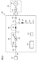
- Fig. 1 schematically illustrates an arrangement 100 for testing an electric power generation system 115.
- the arrangement 100 for testing the electric power generation system (also referred to as test arrangement) comprises an input terminal 113 for connecting the arrangement 100 to an output terminal 116 of the power generation system 122 comprising the generating plant 115 and an optionally generating plant transformer 114.
- the generating plant 115 is directly connected to the input terminal 113 without having the transformer 114 interposed in between.
- the test arrangement 100 further comprises a grid terminal 102 for connecting the arrangement 100 to the utility grid 101.
- the utility grid 101 provides a predetermined first voltage at the grid terminal 102.
- the test arrangement 100 is adapted for testing the power generation system 122 (114, 115) by supplying an overvoltage at the input terminal 113.
- the overvoltage (also referred to as second voltage) is larger than the first voltage at which the utility grid is designed to operate and which is applied at the grid terminal 102.
- a switch 103, a switch 105a, a transformer 105, a switch 105b, a coil or variable or fixed impedance 107 and a switch 112 are connected in series in this order between the grid terminal 102 and the input terminal 113.
- a wire connection comprising a switch 104 is provided for bypassing the transformer 105, when the switch 104 is closed.
- a bypass line is provided comprising a switch 106 for bypassing the coil 107, when the switch 106 is closed.
- the coil 107 is connected between the input terminal 113 and a mid point 117.
- the transformer 105 is connected between the mid point 117 and the grid point 102.
- a coil or variable of fixed impedance 108 (also referred to as first coil) is connected between the switch 112 (leading to the input terminal 113) and a parallel arrangement of switches 109 and 110 which are connected to the reference node 111.
- the test arrangement 100 further comprises a control system 118 for controlling opening and closing of the switches 103, 105a, 105b, 104, 106, 109, 110 and 112 and further for adjusting a transformation ratio of the transformer 105 via not illustrated control lines.
- the test arrangement 100 further comprises a measurement system 119 comprising measurement sensors 120 arranged at different locations within the test arrangement 100 for measuring an electric response of the electric power generation system 122 (114, 115) in response to an overvoltage applied at the input terminal 113.
- the measurement sensors 120 may comprise current measurement sensors and/or voltage measuring sensors.
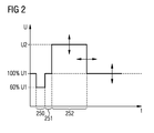
- Fig. 2 schematically illustrates a diagram of a voltage course U at the input terminal 113 and 313, respectively, according to an embodiment of performing a method for testing the electric power generation system using the arrangement 100 or 300 for testing an electric power generation system, as illustrated in Fig. 1 or Fig. 3 .
- the time t is illustrated, while on an ordinate the voltage U at the input terminal 113 or 313 is illustrated.
- the voltage U amounts to 100% U1, corresponding to the nominal operation voltage of the utility grid 1 (U1 may also be referred to as first voltage).
- the situation, when the nominal voltage U1 is applied at the input terminal 113, 313 represents a normal operation of the electric power generation system 114, 115, i.e. a situation or operation when the electric power generation system is not being tested.
- This operational state may be achieved by closing the switches 103, 104, 106 and 112.
- the switches 105a, 105b, 109 and 110 are opened.
- the lengths of the time intervals 250, 251 and 252 may be appropriately adjusted by correspondingly switching the switches 103, 104, 105a, 105b, 106, 109, 110, 309a, 310a and 112 by controlling these switches using the control system 118 or 318, respectively.
- the magnitude of the voltage drop from 100% of the nominal voltage to a lower voltage value may be achieved by appropriately selecting and adjusting the impedances 107, 108 or 307 and 308, respectively.
- the amount of increase from the nominal voltage U1 to the overvoltage U2 may be adjusted by appropriately adjusting a transformation ratio of the transformer 105, 305.
- Fig. 3 schematically illustrates an arrangement 300 for testing an electric power generation system 314, 315 according to another embodiment. Elements corresponding in structure and/or function to elements illustrated in Fig. 1 are denoted with the same reference signs differing only in the first digit. A number of elements comprised in the test arrangement 300 are similar to elements comprised in the test arrangement 100 illustrated in Fig. 1 .
- the impedance 308 is connected via a series arrangement of switches 309a and 310a to the short-cut reference point 311.
- the arrangement of series connected switches 309a and 310a enables faster switching, in particular if the switches 309a and 310a are mechanical switches.
- the switches comprised in the arrangements 100 or 300 may comprise controllable switches, such as transistors.
Abstract
Description
- The present invention relates to an arrangement and to a method for testing an electric power generation system, in particular a wind turbine system, connected to an utility grid for testing the electric power generation system when an overvoltage occurs at the utility grid.
- An electric power generation system, in particular a wind turbine system, supposed to be connected to an utility grid may be required to satisfy particular electrical properties and a particular electrical behaviour when subjected to different electrical situations. In particular, it may be necessary for the electric power generation system to withstand a voltage drop occurring at the utility grid.
- It has however been observed that situations other than a voltage drop may occur at the utility grid. In particular, the utility grid may under certain load conditions or energy supply conditions provide a voltage at a grid terminal via which the electric power generation system is connected to the utility grid, wherein the provided voltage is higher than a predetermined operation voltage of the utility grid. Thereby, the operation of the electric power generation system may be deteriorated or in the worst case the electric power generation system may be damaged or even destroyed.
- There may be a need for an arrangement and for a method for testing an electric power generation system, in particular a wind turbine system, connected to an utility grid, wherein the arrangement for testing is improved compared to a conventional test equipment.
- This need may be met by the subject matter according to the independent claims. Advantageous embodiments of the present invention are described by the dependent claims.
- According to an embodiment an arrangement (in particular comprising one or more electric or electronic components including wire connections) for testing (in particular examining or analyzing an electric behaviour or an electric property of the electric power generation system) an electric power generation system (a system designed for generating electric power by supplying electric voltage and/or electric current to one or more output terminals of the electric power generation system), in particular a wind turbine system (in particular comprising a wind turbine tower, a nacelle mounted on top of the wind turbine tower, a rotor shaft rotatably supported within the nacelle and having fixed thereon one or more rotor blades, and an electrical generator mechanically connected to the rotation shaft for generating an electric current and/or an electric voltage, i.e. a power signal, upon rotation of the rotation shaft at one or more output terminals of the wind turbine system, the electric power in particular being provided via an alternating electric power signal having a variable frequency in accordance with a rotational speed of the rotation shaft) , being connected to an utility grid (being in particular a power network on one hand connected to one or more electric power generation systems that supply electric energy to the utility grid and being on the other hand connected to one or more consumers or loads consuming the electric power supplied by the electric power generation systems, wherein the utility grid may be operated at a particular predetermined frequency, such as 50 Hz or 60 Hz, and wherein the utility grid may operate at a predetermined operation voltage or predetermined first voltage which may amount to between 10 kV and 50 kV depending on the local regulations providing a predetermined first voltage (in particular at a grid supply terminal for supplying electric energy, in particular an electric power signal, from the electric power generation system), wherein the arrangement comprises an input terminal (in particular comprising one or more input terminals for each electrical phase, such as two phases, three phases, or even more phases) for connecting the arrangement to an output terminal (where the electric power signal is output) of the power generation system; a grid terminal (in particular comprising one or more grid terminals for each phase the grid is operating in, such as two phases, three phases or even more phases) for connecting the arrangement to the utility grid; a transformer (an electric device that transfers electrical energy from one circuit to another through inductively coupled conductors, wherein a varying current in the first or primary winding may create a varying magnetic flux in the transformer's core and thus a varying magnetic field through the secondary winding, wherein at terminals of the secondary winding the transformed voltage being higher or lower than the input voltage is applied) temporarily (in particular during short time intervals, such as a time interval between 0.1 ms and 1 s) connectable (in particular via one or more switches which may in particular be controlled by a control system) between the input terminal and the grid terminal (which still allows that one or more other electric or electronic components are arranged on one hand between the grid terminal and the transformer and on the other hand between the transformer and the input terminal), wherein the transformer is adapted to transform the first voltage (in particular the operation voltage of the utility grid) to a second voltage which is different from the first voltage (wherein in particular a frequency of the first voltage equals the frequency of the second voltage, wherein in particular the second voltage is higher than the first voltage); and a measurement system (in particular comprising one or more current sensors and/or one or more voltage sensors) for measuring a current flow through the input terminal (in particular through a wire leading through the input terminal).
- Thereby, it is enabled to examine, to analyze or to test a behavior of an electric power generation system, when the electric power generation system is subjected to an overvoltage at its output terminal (or at its output terminals). Further, it is enabled to generate the overvoltage using the test arrangement by connecting the test arrangement between the utility grid and the electric power generation system, by adjusting a transformation ratio of the transformer appropriately and connecting the adjusted transformer between the input terminal (which is connected to the electric power generation system) and the grid terminal (which is connected to the utility grid). In particular, the measurement system may be adapted to measure a current flow at a number of locations within the arrangement for testing the electric power generation system, wherein measurement of the current flow at these locations is indicative of the electrical behavior of the electric power generation system.
- Thus, the test arrangement is adapted to examine or test the behaviour of the electric power generation system in case of an overvoltage applied at a grid terminal of the utility grid, wherein the electric power generation system is subjected to a higher voltage than the electric power generation system is configured to operate in a normal condition.
- According to an embodiment the second voltage is greater than the first voltage by an amount between 5% and 100%, in particular between 10% and 70%, further in particular between 30% and 50%, of the first voltage. Thus, typical overvoltages currently occurring at an utility grid may be simulated using the test arrangement. Thereby the electric power generation system may be subjected to overvoltages actually frequently occurring in current utility grids. According to other embodiments the second voltage may be even larger than 100% of the first voltage.
- According to an embodiment the transformer is configured (in particular by providing a primary winding, by providing a secondary winding inductively coupled to the primary winding and adjusting or selecting a number of turns in the primary winding and a number of turns in the secondary winding, thereby in particular adjusting or configuring a ratio of the number of turns in the secondary coil relative to the number of turns in the primary coil) such that a ratio between the first voltage and the second voltage may be variably adjusted, in particular to a ratio between 1:1 and 1:1.5. Thereby, the second voltage may be generated in a simple manner by appropriately adjusting a ratio of the number of turns in the secondary winding relative to the number of turns in the primary winding of the transformer and/or by providing one or more tapping connections at the secondary winding.
- According to an embodiment the transformer comprises a tapped transformer. Thereby a tapped transformer may be characterized by one or more connection nodes or connection points along a winding of the transformer, in particular along the secondary winding of the transformer, wherein at the one or more connection points voltages transformed at different transformation ratios may be received. By receiving the transformed voltage at a particular connection point the second voltage may be variably adjusted. In other embodiments another type of transformer may be used, in particular for example comprising more than one secondary windings, the secondary windings having different numbers of turns. To adjust the second voltage one or more switches may be employed for setting the connections to the tapped transformer appropriately.
- According to an embodiment the test arrangement further comprises an electric control system (for example comprising a data processing system, a computer, one or more relays and signal or control lines for connecting the electric control system to one or more components of the test arrangement, such as the transformer, switches in the test arrangement and/or one or more coils) adapted to maintain the second voltage for a predetermined time interval of between 0.1 ms and 1 s, in particular of between 1 ms and 50 ms.
- In particular, the control system may be adapted to perform a sequence of actions such as switching actions to configure the transformator, to actuate a voltage dropping system for dropping the voltage at the input terminal, to connect the transformator between the grid terminal and the input terminal and to deactivate the voltage dropping system such that the overvoltage, in particular the second voltage is applied to the input terminal. The predetermined time interval may depend on the particular application and on local regulations. In particular, the predetermined time interval may be selected such that a damage to the electric power generation system does not occur. Thereby, the testing procedure for testing the electric power generation system may be improved.
- According to an embodiment the electric control system comprises a controllable switch (wherein opening and/or closing the controllable switch may be controlled, in particular by the electric control system) connected in parallel to the transformer. Thereby, the controllable switch may bypass the transformer when the controllable switch is closed. Thereby, the grid terminal may be directly connected (via the controllable switch) to the input terminal.
- According to an embodiment the control system comprises a controllable series switch system connected in series with the transformer between the input terminal and the grid terminal to disconnect the transformer from the utility grid and/or from the input terminal. In particular, the controllable series switch system may comprise two series switches, one of which may be connected between the grid terminal and the transformer and the other of which may be connected between the transformer and the input terminal. In particular, when opening the controllable series switch system, in particular the two series switches, the transformer may be disconnected from the grid terminal and may also be disconnected from the input terminal. When at the same time the switch connected in parallel to the transformer is closed, the transformer will by bypassed such that the voltage at the grid terminal is fed to the input terminal. Thereby, controlling a voltage course for applying the overvoltage at the electric power generation system may be facilitated. In particular, when closing the controllable series switch system, in particular the two series switches, the transformer may be connected to the grid terminal and may also be connected to the input terminal. When at the same time the switch connected in parallel to the transformer is opened, the second voltage may be applied at the input terminal.
- According to an embodiment the control system further comprises a first coil (or an inductor or in general a electrical component having an impedance being characterized by an imaginary resistance which increases with increasing frequency) connected between the input terminal and a reference node (which may in particular be connected to a ground potential or earth potential), in particular via at least one reference node switch. In particular, when the at least one reference node switch is closed a voltage at the input terminal may drop due to electric current flow through the first coil towards the reference node.
- Thereby, controlling or regulating the voltage at the input terminal may be performed in a more flexible and simple way. In particular, the at least one reference node switch may comprise two series connected switches which are connected between the first coil and the reference node or which may be connected between the first coil and the input terminal. Alternatively, the at least one reference node switch may comprise two parallelly connected switches, wherein the parallelly connected switches are connected between the first coil and the reference node or the parallelly connected switches are connected between the first coil and the input node or input terminal. Thereby, it may be achieved to reduce the voltage at the input terminal according to a predetermined time course.
- According to an embodiment the test arrangement may also be employed for generating a voltage drop at the input terminal via the current flow through the first coil. Further, the electrical behavior of the electric power generation system upon the generated voltage drop at the input terminal may be examined and analyzed.
- According to an embodiment the measurement system is adapted for measuring a current flow at a point between the first coil and the reference node and/or at the grid terminal. Thereby, further parameters of the electric generation system may be acquired or measured. Thereby, the test arrangement may be improved.
- According to an embodiment the control system further comprises a second coil (or inductor or impedance having a resistance increasing with increasing frequency) connected between the input terminal and a mid node, wherein the transformer is connected between the mid node and the grid terminal and wherein the control system in particular comprises a switch connected in parallel to the second coil. In particular, by closing the switch connected in parallel to the second coil the second coil may be bypassed. In particular, the second coil may limit a voltage drop at the input terminal such that a voltage drop smaller than the voltage drop at the input terminal is applied to the grid terminal.
- According to an embodiment the measurement system is further adapted for measuring a voltage between a fixed potential node and the input terminal and/or the grid terminal. Thereby, the behavior of the electric power generation system may more thoroughly be analyzed. Further, the measurement system may be adapted to measure voltages at even more locations with respect to a fixed potential node (such as a ground potential or earth potential).
- It should be noted that features (individually or in any combination) disclosed, described, explained or mentioned with respect to an arrangement for testing an electric power generation system may individually or in any combination also applied to a method for testing an electric power generation system and vice versa.
- According to an embodiment a method for testing an electric power generation system, in particular a wind turbine system, being connected to an utility grid is provided, wherein the method comprises connecting (in particular electrically connecting or electrically coupling) the arrangement, via an input terminal, to an output terminal of the power generation system; connecting (in particular electrically connecting) the arrangement, via a grid terminal, to the utility grid providing a predetermined first voltage; transforming the first voltage to a second voltage which is different from the first voltage using a transformer connected between the input terminal and the grid terminal, and measuring a current flow through the input terminal using a measurement system.
- In particular the measurement system may be adapted to examine the electric response of the electric power generation system upon applying the second voltage at the input terminal. The electric response of the electric power generation system may comprise an evolution (or time course) of a voltage at the input terminal, an evolution of a current flowing through the input terminal and/or a combination of the evolution of the current and the evolution of the voltage. Further, the measurement system may comprise a processing system for evaluating or processing the measured voltage and/or current values. For example, the measured current and/or voltage values may be compared to predetermined voltage and current criteria.
- According to an embodiment the transforming the first voltage to the second voltage comprises disconnecting the transformer from the grid terminal (in particular by opening a series switch connected between the transformer and the grid terminal and further in particular by also opening a series switch connected between the transformer and the input terminal); adjusting (in particular comprising connecting an output terminal of the transformer to a particular connection point of a tapped transformer) a transformation ratio (which in particular defines a ratio of a voltage provided or output at the secondary winding relative to a voltage set or input at a primary winding of the transformer) of the transformer for transforming the first voltage to the second voltage (in particular during adjusting the transformation ratio the transformer is still disconnected from the grid terminal and in particular also disconnected from the input terminal); connecting the utility grid to the input terminal (in particular via a switch connected in parallel to the transformer, wherein the closed switch connected in parallel to the transformer bypasses the transformer such that the utility grid is connected via the bypass switch to the input terminal), reducing a voltage at the input terminal via a current flow via a first coil and a second coil towards a reference point (while the transformer is still disconnected from the grid terminal and is also still disconnected from the input terminal, wherein the electric power generation system is subjected to the reduced voltage at the input terminal, wherein the reduced voltage is lower than the first voltage); connecting the transformer to the grid terminal (and in particular also connecting the transformer to the second coil and in particular also opening the bypass switch parallelly connected to the transformer); and disconnecting the first coil from the reference node.
- Thereby, the reducing the voltage at the input terminal is achieved by a current flow via a first coil which is connected between the grid terminal and the input terminal and via a second coil which is connected between the input terminal and a reference node towards a reference point (the current flow flows through the second coil and the first coil towards the reference node thereby causing a voltage drop at the input terminal).
- Disconnecting the first coil from the reference node in particular abolishes the reducing of the voltage at the input terminal by the current flow through the second coil and the first coil. In particular, the disconnecting the first coil from the reference node may comprise opening at least one reference node switch connected between the first coil and the reference point or reference node or connected between the first coil and the input terminal. In particular disconnecting the first coil from the reference node may be performed in a faster way than connecting the transformer between the grid terminal and the input terminal. Thereby, an overvoltage may be applied at the input terminal for a shorter period of time by disconnecting the first coil from the reference node than by exclusively connecting the transformer between the grid terminal and the input terminal without using the first coil (and the second coil).
- According to an embodiment the transforming the first voltage to the second voltage comprises applying the first voltage at the input terminal, while the transformer is connected to the grid terminal (and while the transformer is also connected to the second coil) and while the voltage at the input terminal is reduced by the current flow via the first coil and the second coil towards the reference point (thus, by reducing the voltage at the input terminal by the current flow via the second coil and the first coil the second voltage fed to the output terminal of the transformer is reduced such that the first voltage is applied at the input terminal); and applying the second voltage at the input terminal, while the first coil is disconnected from the reference node (thus disconnecting the first coil from the reference node abolishes the reduction of the voltage from the second voltage to the first voltage such that the second voltage generated by the transformer is applied at the input terminal).
- According to other embodiments other sequences of switchings to disconnect or connect the transformer, the first coil and/or the second coil to the grid terminal, the input terminal and/or the reference node may be performed in a different way.
- It has to be noted that embodiments of the invention have been described with reference to different subject matters. In particular, some embodiments have been described with reference to method type claims whereas other embodiments have been described with reference to apparatus type claims. However, a person skilled in the art will gather from the above and the following description that, unless other notified, in addition to any combination of features belonging to one type of subject matter also any combination between features relating to different subject matters, in particular between features of the method type claims and features of the apparatus type claims is considered as to be disclosed with this document.
- The aspects defined above and further aspects of the present invention are apparent from the examples of embodiment to be described hereinafter and are explained with reference to the examples of embodiment. The invention will be described in more detail hereinafter with reference to examples of embodiment but to which the invention is not limited.
- Embodiments of the present invention are now described by reference to the accompanying drawings to which the invention is not limited.
-
Fig. 1 schematically illustrates an arrangement for testing an electric power generation system according to an embodiment; -
Fig. 2 schematically illustrates a diagram of a time course of a voltage to which the electric power generation system illustrated inFig. 1 is subjected using the arrangement for testing the electric power generation system illustrated inFig. 1 orFig. 3 ; and -
Fig. 3 schematically illustrates an arrangement for testing an electric power generation system according to another embodiment. - The illustration in the drawing is schematic. It is noted that in different figures, similar or identical elements are provided with the same reference signs or with reference signs, which are different from the corresponding reference signs only within the first digit.
-
Fig. 1 schematically illustrates anarrangement 100 for testing an electricpower generation system 115. Thearrangement 100 for testing the electric power generation system (also referred to as test arrangement) comprises an input terminal 113 for connecting thearrangement 100 to anoutput terminal 116 of thepower generation system 122 comprising thegenerating plant 115 and an optionally generatingplant transformer 114. In other embodiments thegenerating plant 115 is directly connected to the input terminal 113 without having thetransformer 114 interposed in between. - The
test arrangement 100 further comprises agrid terminal 102 for connecting thearrangement 100 to theutility grid 101. In the illustrated embodiment theutility grid 101 provides a predetermined first voltage at thegrid terminal 102. Thetest arrangement 100 is adapted for testing the power generation system 122 (114, 115) by supplying an overvoltage at the input terminal 113. The overvoltage (also referred to as second voltage) is larger than the first voltage at which the utility grid is designed to operate and which is applied at thegrid terminal 102. Aswitch 103, aswitch 105a, atransformer 105, aswitch 105b, a coil or variable or fixedimpedance 107 and aswitch 112 are connected in series in this order between thegrid terminal 102 and the input terminal 113. - In parallel to the
transformer 105 a wire connection comprising aswitch 104 is provided for bypassing thetransformer 105, when theswitch 104 is closed. Further, a bypass line is provided comprising aswitch 106 for bypassing thecoil 107, when theswitch 106 is closed. Herein, thecoil 107 is connected between the input terminal 113 and amid point 117. Thetransformer 105 is connected between themid point 117 and thegrid point 102. - A coil or variable of fixed impedance 108 (also referred to as first coil) is connected between the switch 112 (leading to the input terminal 113) and a parallel arrangement of
switches reference node 111. - The
test arrangement 100 further comprises acontrol system 118 for controlling opening and closing of theswitches transformer 105 via not illustrated control lines. Thetest arrangement 100 further comprises ameasurement system 119 comprisingmeasurement sensors 120 arranged at different locations within thetest arrangement 100 for measuring an electric response of the electric power generation system 122 (114, 115) in response to an overvoltage applied at the input terminal 113. Themeasurement sensors 120 may comprise current measurement sensors and/or voltage measuring sensors. -
Fig. 2 schematically illustrates a diagram of a voltage course U at theinput terminal 113 and 313, respectively, according to an embodiment of performing a method for testing the electric power generation system using thearrangement Fig. 1 orFig. 3 . On an abscissa of the diagram illustrated inFig. 2 the time t is illustrated, while on an ordinate the voltage U at theinput terminal 113 or 313 is illustrated. At time t=0 the voltage U amounts to 100% U1, corresponding to the nominal operation voltage of the utility grid 1 (U1 may also be referred to as first voltage). The situation, when the nominal voltage U1 is applied at theinput terminal 113, 313 represents a normal operation of the electricpower generation system switches switches Fig. 3 ) are opened. - To subject the electric power generation system 122 (114, 115) to the second voltage U2 at the
input terminal 113, 313, the following method steps may be performed: - 1. The
transformer transformer 105 is neither connected to thegrid terminal 102 nor connected to the input terminal 113, since theswitches - 2. The electric
power generation system - 3. The
impedances 107 and 108 (or coils 107 and 108) are adjusted such that a voltage drop of 0.6 times the nominal voltage U1 would result if theseimpedances - 4. Switch 106 (306) will be opened so that impedance 107 (307) is not any more bypassed and switches 109 and/or 110 (or alternatively switches 109a and 110a, as illustrated in
Fig. 3 ) will be closed. Thereby, a reduction of the voltage by 40% at the input terminal 113 may be achieved. This situation is illustrated in thetime interval 250, as illustrated inFig. 2 , in which the voltage U at theinput terminal 113, 313 amounts to about 60% of the nominal voltage U1. - 5. After that switch 104 (304) will be opened and the
switches transformer 105 is not bypassed via the switch 104 (304) any more. - 6. Thus, the voltage U at the
input terminal 113, 313 increases by 40% to again reach 100% of the nominal voltage U1, as is illustrated in thetime interval 251 inFig. 2 . - 7. At this point the power generation system, here a wind turbine system is started up to reach a working point or a normal operation condition.
- 8. When the wind turbine system has reached the normal operational state, the
switches switch 109 when theswitch 110 was open or theswitch 110, when theswitch 109 was open) will be opened. Thereby, no voltage drop occurs via the current flow through theimpedance - 9. The voltage U at the
input terminal 113, 313 increases to the second voltage U2 in thetime interval 252, as illustrated inFig. 2 . - 10. After having applied the second voltage U2 at the
input terminal 113, 313 the electrical response of thepower generation system measurement systems
After a desired time period of applying the second voltage U2 to theinput terminal 113, 313 theswitch Fig. 3 ); or theswitch 110 will be closed, whenswitch 109 is opened or 109 will be closed when theswitch 110 was opened (compareFig. 1 ). - 11. Thereby, the voltage U drops from the value U2 back to 100% of the nominal voltage U1 to thus complete the generation and application of the voltage jump.
- The lengths of the
time intervals switches control system impedances transformer input terminal 113, 313 is achieved according to an embodiment of the present invention. -
Fig. 3 schematically illustrates anarrangement 300 for testing an electricpower generation system Fig. 1 are denoted with the same reference signs differing only in the first digit. A number of elements comprised in thetest arrangement 300 are similar to elements comprised in thetest arrangement 100 illustrated inFig. 1 . - In contrast to the configuration of parallelly arranged
switches impedance 108 to the reference point or short-cut reference point 111 theimpedance 308 is connected via a series arrangement ofswitches cut reference point 311. The arrangement of series connectedswitches switches arrangements - It should be noted that the term "comprising" does not exclude other elements or steps and "a" or "an" does not exclude a plurality. Also elements described in association with different embodiments may be combined. It should also be noted that reference signs in the claims should not be construed as limiting the scope of the claims.
Claims (14)
- Arrangement for testing an electric power generation system, in particular a wind turbine system, being connected to an utility grid providing a predetermined first voltage, the arrangement comprising:● a input terminal (113, 313) for connecting the arrangement to an output terminal (116, 316) of the power generation system;● a grid terminal (102, 302) for connecting the arrangement to the utility grid (101, 301);● a transformer (105, 305) temporarily connectable between the input terminal and the grid terminal, wherein the transformer is adapted to transform the first voltage (U1) to a second voltage (U2) which is different from the first voltage; and● a measurement system (119, 319) adapted for measuring a current flow through the input terminal.
- Arrangement according to claim 1, wherein the second voltage is greater than the first voltage by an amount between 5% and 100%, in particular between 10% and 70%, further in particular between 30% and 50%, of the first voltage.
- Arrangement according to claim 1 or 2, wherein the transformer is configured such that a ratio between the first voltage and the second voltage may be variably adjusted, in particular to a ratio between 1:1 and 1:1.5.
- Arrangement according to one of the preceding claims, wherein the transformer comprises a tapped transformer.
- Arrangement according to one of the preceding claims, further comprising:● an electric control system (118, 318) adapted to maintain the second voltage for a predetermined time interval (252) of between 0.1 ms and 1 s, in particular of between 1 ms and 50 ms.
- Arrangement according to claim 5, wherein the electric control system comprises a controllable switch (104, 304) connected in parallel to the transformer.
- Arrangement according to claim 5 or 6, wherein the control system comprises a controllable series switch system (105a, 105b, 305a, 305b) connected in series with the transformer between the input terminal and the grid terminal to disconnect the transformer from the utility grid and/or from the input terminal.
- Arrangement according to one of claims 5 to 7, wherein the control system further comprises a first coil (108, 308) connected between the input terminal and a reference node (111, 311), in particular via at least one reference node switch (109, 110; 109a, 110a).
- Arrangement according to claim 8, wherein the measurement system is adapted for measuring a current flow at a point between the first coil and the reference node and/or at the grid terminal.
- Arrangement according to one of claims 5 to 9, wherein the control system further comprises a second coil (107, 307) connected between the input terminal and a mid node (117, 317), wherein the transformer is connected between the mid node and the grid terminal, wherein the control system in particular comprises a switch (106, 306) connected in parallel to the second coil.
- Arrangement according to one of the preceding claims, wherein the measurement system is further adapted for measuring a voltage between a fixed potential node and the input terminal and/or the grid terminal.
- Method for testing an electric power generation system, in particular a wind turbine system, being connected to an utility grid, the method comprising:● connecting the arrangement, via an input terminal (113, 313), to an output terminal (116, 316) of the power generation system (115, 315);● connecting the arrangement, via a grid terminal (102, 302), to the utility grid providing a predetermined first voltage (U1) ;● transforming the first voltage (U1) to a second voltage (U2) which is different from the first voltage using a transformer (105, 305) connected between the input terminal and the grid terminal,● measuring a current flow through the input terminal using a measurement system (119, 120, 319, 320).
- Method according to claim 12, wherein the transforming the first voltage to the second voltage comprises:disconnecting the transformer from the grid terminal;adjusting a transformation ratio of the transformer for transforming the first voltage to the second voltage;connecting the utility grid to the input terminal;reducing a voltage at the input terminal by a current flow via a second coil (107, 307) which is connected between the grid terminal and the input terminal and a first coil (108, 308) which is connected between the input terminal and a reference point (111, 311) towards the reference point;connecting the transformer to the grid terminal; anddisconnecting the first coil from the reference node.
- Method according to claim 13, wherein the transforming the first voltage to the second voltage comprises:applying the first voltage at the input terminal, while the transformer is connected to the grid terminal and while the voltage at the input terminal is reduced by the current flow via the first coil and the second coil towards the reference point; andapplying the second voltage at the input terminal, while the first coil is disconnected from the reference node.
Priority Applications (5)
| Application Number | Priority Date | Filing Date | Title |
|---|---|---|---|
| DK10194175.5T DK2463674T3 (en) | 2010-12-08 | 2010-12-08 | Arrangement and method for testing a system of electricity generation |
| EP10194175.5A EP2463674B1 (en) | 2010-12-08 | 2010-12-08 | Arrangement and method for testing an electric power generation system |
| US13/286,283 US20120144909A1 (en) | 2010-12-08 | 2011-11-01 | Arrangement and method for testing an electric power generation system |
| CA2760713A CA2760713A1 (en) | 2010-12-08 | 2011-12-06 | Arrangement and method for testing an electric power generation system |
| CN2011104056021A CN102540073A (en) | 2010-12-08 | 2011-12-08 | Arrangement and method for testing electric power generation system |
Applications Claiming Priority (1)
| Application Number | Priority Date | Filing Date | Title |
|---|---|---|---|
| EP10194175.5A EP2463674B1 (en) | 2010-12-08 | 2010-12-08 | Arrangement and method for testing an electric power generation system |
Publications (2)
| Publication Number | Publication Date |
|---|---|
| EP2463674A1 true EP2463674A1 (en) | 2012-06-13 |
| EP2463674B1 EP2463674B1 (en) | 2013-07-03 |
Family
ID=44041741
Family Applications (1)
| Application Number | Title | Priority Date | Filing Date |
|---|---|---|---|
| EP10194175.5A Not-in-force EP2463674B1 (en) | 2010-12-08 | 2010-12-08 | Arrangement and method for testing an electric power generation system |
Country Status (5)
| Country | Link |
|---|---|
| US (1) | US20120144909A1 (en) |
| EP (1) | EP2463674B1 (en) |
| CN (1) | CN102540073A (en) |
| CA (1) | CA2760713A1 (en) |
| DK (1) | DK2463674T3 (en) |
Families Citing this family (7)
| Publication number | Priority date | Publication date | Assignee | Title |
|---|---|---|---|---|
| EP2461026B2 (en) * | 2010-12-03 | 2016-12-21 | Siemens Aktiengesellschaft | Arrangement and method for testing an electric power generation system |
| JP5497115B2 (en) * | 2012-01-27 | 2014-05-21 | 三菱電機株式会社 | Power switching device and switchboard |
| US20130335061A1 (en) * | 2012-06-15 | 2013-12-19 | GRID20/20, Inc. | Systems and Methods for Monitoring Underground Power Lines |
| CN103278717B (en) * | 2013-05-24 | 2015-08-19 | 北京荣华恒信开关技术有限公司 | The grid-connected proving installation of new forms of energy integration |
| DE102015201857A1 (en) * | 2015-02-03 | 2016-08-04 | Wobben Properties Gmbh | Wind turbine testing apparatus and method for testing a wind turbine |
| DE102015114126A1 (en) | 2015-08-26 | 2017-03-02 | Wobben Properties Gmbh | Wind turbine testing apparatus and method for testing a wind turbine |
| ES2778824T3 (en) | 2017-02-28 | 2020-08-12 | Nordex Energy Gmbh | Procedure and device for examining an electricity generating unit |
Citations (10)
| Publication number | Priority date | Publication date | Assignee | Title |
|---|---|---|---|---|
| US5798632A (en) * | 1995-07-18 | 1998-08-25 | Midwest Research Institute | Variable speed wind turbine generator with zero-sequence filter |
| US6111767A (en) * | 1998-06-22 | 2000-08-29 | Heliotronics, Inc. | Inverter integrated instrumentation having a current-voltage curve tracer |
| US20030227172A1 (en) * | 2002-06-07 | 2003-12-11 | Erdman William L. | Wind farm electrical system |
| EP1801414A2 (en) * | 2005-12-20 | 2007-06-27 | The General Electric Company | System and methods for testing a wind turbine |
| US20070241759A1 (en) * | 2006-04-07 | 2007-10-18 | Michael Lamar Williams | Method for measuring stability margin at a node of a polyphase power grid |
| WO2007140789A1 (en) * | 2006-07-03 | 2007-12-13 | Vestas Wind Systems A/S | Wind turbine testing system |
| WO2008109264A1 (en) * | 2007-03-01 | 2008-09-12 | Wisconsin Alumni Research Foundation | Control of combined storage and generation in distributed energy resources |
| EP2072813A2 (en) * | 2007-12-19 | 2009-06-24 | General Electric Company | Control system and method for operating a wind farm |
| EP2141788A2 (en) * | 2008-06-30 | 2010-01-06 | General Electric Company | Optimizing converter protection for wind turbine generators |
| US20100010684A1 (en) * | 2007-05-07 | 2010-01-14 | Lorenz Rick A | Protection techniques for an electric power system |
Family Cites Families (3)
| Publication number | Priority date | Publication date | Assignee | Title |
|---|---|---|---|---|
| DK2035698T3 (en) * | 2006-07-03 | 2017-07-24 | Vestas Wind Sys As | Test stand and a method for testing wind turbine equipment |
| ES2377841T3 (en) * | 2006-07-03 | 2012-04-02 | Vestas Wind Systems A/S | Test bench comprising an angle adjustment means and procedures for testing wind turbine equipment |
| EP2461026B2 (en) * | 2010-12-03 | 2016-12-21 | Siemens Aktiengesellschaft | Arrangement and method for testing an electric power generation system |
-
2010
- 2010-12-08 DK DK10194175.5T patent/DK2463674T3/en active
- 2010-12-08 EP EP10194175.5A patent/EP2463674B1/en not_active Not-in-force
-
2011
- 2011-11-01 US US13/286,283 patent/US20120144909A1/en not_active Abandoned
- 2011-12-06 CA CA2760713A patent/CA2760713A1/en not_active Abandoned
- 2011-12-08 CN CN2011104056021A patent/CN102540073A/en active Pending
Patent Citations (10)
| Publication number | Priority date | Publication date | Assignee | Title |
|---|---|---|---|---|
| US5798632A (en) * | 1995-07-18 | 1998-08-25 | Midwest Research Institute | Variable speed wind turbine generator with zero-sequence filter |
| US6111767A (en) * | 1998-06-22 | 2000-08-29 | Heliotronics, Inc. | Inverter integrated instrumentation having a current-voltage curve tracer |
| US20030227172A1 (en) * | 2002-06-07 | 2003-12-11 | Erdman William L. | Wind farm electrical system |
| EP1801414A2 (en) * | 2005-12-20 | 2007-06-27 | The General Electric Company | System and methods for testing a wind turbine |
| US20070241759A1 (en) * | 2006-04-07 | 2007-10-18 | Michael Lamar Williams | Method for measuring stability margin at a node of a polyphase power grid |
| WO2007140789A1 (en) * | 2006-07-03 | 2007-12-13 | Vestas Wind Systems A/S | Wind turbine testing system |
| WO2008109264A1 (en) * | 2007-03-01 | 2008-09-12 | Wisconsin Alumni Research Foundation | Control of combined storage and generation in distributed energy resources |
| US20100010684A1 (en) * | 2007-05-07 | 2010-01-14 | Lorenz Rick A | Protection techniques for an electric power system |
| EP2072813A2 (en) * | 2007-12-19 | 2009-06-24 | General Electric Company | Control system and method for operating a wind farm |
| EP2141788A2 (en) * | 2008-06-30 | 2010-01-06 | General Electric Company | Optimizing converter protection for wind turbine generators |
Also Published As
| Publication number | Publication date |
|---|---|
| CA2760713A1 (en) | 2012-06-08 |
| DK2463674T3 (en) | 2013-09-02 |
| EP2463674B1 (en) | 2013-07-03 |
| US20120144909A1 (en) | 2012-06-14 |
| CN102540073A (en) | 2012-07-04 |
Similar Documents
| Publication | Publication Date | Title |
|---|---|---|
| EP2463674B1 (en) | Arrangement and method for testing an electric power generation system | |
| EP2461026B1 (en) | Arrangement and method for testing an electric power generation system | |
| DK2332229T3 (en) | TESTING INSTALLATION FOR WIND ENERGY INSTALLATIONS | |
| Ribeiro et al. | Power systems signal processing for smart grids | |
| Aithal et al. | Performance of an electrical distribution network with Soft Open Point during a grid side AC fault | |
| EP2461027B1 (en) | Arrangement and method for testing an electric power generation system | |
| EP1879091A1 (en) | Voltage sag generator device | |
| EP2680019A1 (en) | Device that generates electrical disturbances | |
| Tatcho et al. | A novel line section protection for the FREEDM system based on the solid state transformer | |
| WO2010069989A2 (en) | Method and system for testing wind turbine plants | |
| Gabe et al. | Design of a voltage sag generator based on impedance switching | |
| CN108802531A (en) | A kind of high-low voltage ride through test device and test method having shorted to earth function | |
| Dhara et al. | A fault current limiter circuit to improve transient stability in power system | |
| Booth et al. | The Power Networks Demonstration Centre: An environment for accelerated testing, demonstration and validation of existing and novel protection and automation systems | |
| Saleh et al. | Experimental assessment of grounding system impacts on ground currents and transient overvoltage | |
| Zhao et al. | Performance analysis of resistive and flux-lock type SFCL in electricity networks with DGs | |
| Cho et al. | Application of controlled switching device for high voltage circuit breaker in KEPCO real power system | |
| Al-Durra et al. | Experimental performance of grounding systems | |
| Balan et al. | Modeling Three-Phase Short-Circuits in Grids Connected to Windfarms | |
| CN111736024B (en) | Test system of power equipment and control method thereof | |
| CN116609650B (en) | Direct current transfer test system and method | |
| US20230288494A1 (en) | Testing of an electrical system of a wind turbine | |
| EP3338335A1 (en) | Switch, distributor system and method of adjusting current imbalance or phase to neutral voltages | |
| Balouji | On Deep Machine Learning Based Techniques for Electric Power Systems | |
| CN116298578A (en) | Dynamic simulation test system and method for internal faults of variable speed pumping and storage unit |
Legal Events
| Date | Code | Title | Description |
|---|---|---|---|
| PUAI | Public reference made under article 153(3) epc to a published international application that has entered the european phase |
Free format text: ORIGINAL CODE: 0009012 |
|
| AK | Designated contracting states |
Kind code of ref document: A1 Designated state(s): AL AT BE BG CH CY CZ DE DK EE ES FI FR GB GR HR HU IE IS IT LI LT LU LV MC MK MT NL NO PL PT RO RS SE SI SK SM TR |
|
| AX | Request for extension of the european patent |
Extension state: BA ME |
|
| 17P | Request for examination filed |
Effective date: 20120709 |
|
| RIC1 | Information provided on ipc code assigned before grant |
Ipc: G05F 1/67 20060101ALI20121206BHEP Ipc: F03D 7/02 20060101ALI20121206BHEP Ipc: G01R 31/34 20060101AFI20121206BHEP Ipc: H02P 9/00 20060101ALI20121206BHEP Ipc: G01R 27/32 20060101ALI20121206BHEP Ipc: F03D 7/00 20060101ALI20121206BHEP |
|
| GRAP | Despatch of communication of intention to grant a patent |
Free format text: ORIGINAL CODE: EPIDOSNIGR1 |
|
| RAP1 | Party data changed (applicant data changed or rights of an application transferred) |
Owner name: SIEMENS AKTIENGESELLSCHAFT |
|
| GRAS | Grant fee paid |
Free format text: ORIGINAL CODE: EPIDOSNIGR3 |
|
| GRAA | (expected) grant |
Free format text: ORIGINAL CODE: 0009210 |
|
| STAA | Information on the status of an ep patent application or granted ep patent |
Free format text: STATUS: THE PATENT HAS BEEN GRANTED |
|
| AK | Designated contracting states |
Kind code of ref document: B1 Designated state(s): AL AT BE BG CH CY CZ DE DK EE ES FI FR GB GR HR HU IE IS IT LI LT LU LV MC MK MT NL NO PL PT RO RS SE SI SK SM TR |
|
| REG | Reference to a national code |
Ref country code: GB Ref legal event code: FG4D |
|
| REG | Reference to a national code |
Ref country code: AT Ref legal event code: REF Ref document number: 620065 Country of ref document: AT Kind code of ref document: T Effective date: 20130715 Ref country code: CH Ref legal event code: EP |
|
| REG | Reference to a national code |
Ref country code: IE Ref legal event code: FG4D |
|
| REG | Reference to a national code |
Ref country code: DE Ref legal event code: R096 Ref document number: 602010008191 Country of ref document: DE Effective date: 20130829 |
|
| REG | Reference to a national code |
Ref country code: DK Ref legal event code: T3 |
|
| PG25 | Lapsed in a contracting state [announced via postgrant information from national office to epo] |
Ref country code: SI Free format text: LAPSE BECAUSE OF FAILURE TO SUBMIT A TRANSLATION OF THE DESCRIPTION OR TO PAY THE FEE WITHIN THE PRESCRIBED TIME-LIMIT Effective date: 20130703 |
|
| REG | Reference to a national code |
Ref country code: AT Ref legal event code: MK05 Ref document number: 620065 Country of ref document: AT Kind code of ref document: T Effective date: 20130703 |
|
| REG | Reference to a national code |
Ref country code: NL Ref legal event code: VDEP Effective date: 20130703 |
|
| REG | Reference to a national code |
Ref country code: LT Ref legal event code: MG4D |
|
| PG25 | Lapsed in a contracting state [announced via postgrant information from national office to epo] |
Ref country code: IS Free format text: LAPSE BECAUSE OF FAILURE TO SUBMIT A TRANSLATION OF THE DESCRIPTION OR TO PAY THE FEE WITHIN THE PRESCRIBED TIME-LIMIT Effective date: 20131103 Ref country code: NO Free format text: LAPSE BECAUSE OF FAILURE TO SUBMIT A TRANSLATION OF THE DESCRIPTION OR TO PAY THE FEE WITHIN THE PRESCRIBED TIME-LIMIT Effective date: 20131003 Ref country code: PT Free format text: LAPSE BECAUSE OF FAILURE TO SUBMIT A TRANSLATION OF THE DESCRIPTION OR TO PAY THE FEE WITHIN THE PRESCRIBED TIME-LIMIT Effective date: 20131104 Ref country code: SE Free format text: LAPSE BECAUSE OF FAILURE TO SUBMIT A TRANSLATION OF THE DESCRIPTION OR TO PAY THE FEE WITHIN THE PRESCRIBED TIME-LIMIT Effective date: 20130703 Ref country code: CY Free format text: LAPSE BECAUSE OF FAILURE TO SUBMIT A TRANSLATION OF THE DESCRIPTION OR TO PAY THE FEE WITHIN THE PRESCRIBED TIME-LIMIT Effective date: 20130828 Ref country code: BE Free format text: LAPSE BECAUSE OF FAILURE TO SUBMIT A TRANSLATION OF THE DESCRIPTION OR TO PAY THE FEE WITHIN THE PRESCRIBED TIME-LIMIT Effective date: 20130703 Ref country code: AT Free format text: LAPSE BECAUSE OF FAILURE TO SUBMIT A TRANSLATION OF THE DESCRIPTION OR TO PAY THE FEE WITHIN THE PRESCRIBED TIME-LIMIT Effective date: 20130703 Ref country code: LT Free format text: LAPSE BECAUSE OF FAILURE TO SUBMIT A TRANSLATION OF THE DESCRIPTION OR TO PAY THE FEE WITHIN THE PRESCRIBED TIME-LIMIT Effective date: 20130703 Ref country code: HR Free format text: LAPSE BECAUSE OF FAILURE TO SUBMIT A TRANSLATION OF THE DESCRIPTION OR TO PAY THE FEE WITHIN THE PRESCRIBED TIME-LIMIT Effective date: 20130703 |
|
| PG25 | Lapsed in a contracting state [announced via postgrant information from national office to epo] |
Ref country code: LV Free format text: LAPSE BECAUSE OF FAILURE TO SUBMIT A TRANSLATION OF THE DESCRIPTION OR TO PAY THE FEE WITHIN THE PRESCRIBED TIME-LIMIT Effective date: 20130703 Ref country code: ES Free format text: LAPSE BECAUSE OF FAILURE TO SUBMIT A TRANSLATION OF THE DESCRIPTION OR TO PAY THE FEE WITHIN THE PRESCRIBED TIME-LIMIT Effective date: 20131014 Ref country code: NL Free format text: LAPSE BECAUSE OF FAILURE TO SUBMIT A TRANSLATION OF THE DESCRIPTION OR TO PAY THE FEE WITHIN THE PRESCRIBED TIME-LIMIT Effective date: 20130703 Ref country code: FI Free format text: LAPSE BECAUSE OF FAILURE TO SUBMIT A TRANSLATION OF THE DESCRIPTION OR TO PAY THE FEE WITHIN THE PRESCRIBED TIME-LIMIT Effective date: 20130703 Ref country code: PL Free format text: LAPSE BECAUSE OF FAILURE TO SUBMIT A TRANSLATION OF THE DESCRIPTION OR TO PAY THE FEE WITHIN THE PRESCRIBED TIME-LIMIT Effective date: 20130703 Ref country code: GR Free format text: LAPSE BECAUSE OF FAILURE TO SUBMIT A TRANSLATION OF THE DESCRIPTION OR TO PAY THE FEE WITHIN THE PRESCRIBED TIME-LIMIT Effective date: 20131004 |
|
| PG25 | Lapsed in a contracting state [announced via postgrant information from national office to epo] |
Ref country code: CY Free format text: LAPSE BECAUSE OF FAILURE TO SUBMIT A TRANSLATION OF THE DESCRIPTION OR TO PAY THE FEE WITHIN THE PRESCRIBED TIME-LIMIT Effective date: 20130703 |
|
| PG25 | Lapsed in a contracting state [announced via postgrant information from national office to epo] |
Ref country code: EE Free format text: LAPSE BECAUSE OF FAILURE TO SUBMIT A TRANSLATION OF THE DESCRIPTION OR TO PAY THE FEE WITHIN THE PRESCRIBED TIME-LIMIT Effective date: 20130703 Ref country code: SK Free format text: LAPSE BECAUSE OF FAILURE TO SUBMIT A TRANSLATION OF THE DESCRIPTION OR TO PAY THE FEE WITHIN THE PRESCRIBED TIME-LIMIT Effective date: 20130703 Ref country code: RO Free format text: LAPSE BECAUSE OF FAILURE TO SUBMIT A TRANSLATION OF THE DESCRIPTION OR TO PAY THE FEE WITHIN THE PRESCRIBED TIME-LIMIT Effective date: 20130703 Ref country code: CZ Free format text: LAPSE BECAUSE OF FAILURE TO SUBMIT A TRANSLATION OF THE DESCRIPTION OR TO PAY THE FEE WITHIN THE PRESCRIBED TIME-LIMIT Effective date: 20130703 |
|
| PLBE | No opposition filed within time limit |
Free format text: ORIGINAL CODE: 0009261 |
|
| STAA | Information on the status of an ep patent application or granted ep patent |
Free format text: STATUS: NO OPPOSITION FILED WITHIN TIME LIMIT |
|
| PG25 | Lapsed in a contracting state [announced via postgrant information from national office to epo] |
Ref country code: IT Free format text: LAPSE BECAUSE OF FAILURE TO SUBMIT A TRANSLATION OF THE DESCRIPTION OR TO PAY THE FEE WITHIN THE PRESCRIBED TIME-LIMIT Effective date: 20130703 |
|
| 26N | No opposition filed |
Effective date: 20140404 |
|
| REG | Reference to a national code |
Ref country code: DE Ref legal event code: R097 Ref document number: 602010008191 Country of ref document: DE Effective date: 20140404 |
|
| PG25 | Lapsed in a contracting state [announced via postgrant information from national office to epo] |
Ref country code: LU Free format text: LAPSE BECAUSE OF FAILURE TO SUBMIT A TRANSLATION OF THE DESCRIPTION OR TO PAY THE FEE WITHIN THE PRESCRIBED TIME-LIMIT Effective date: 20131208 |
|
| REG | Reference to a national code |
Ref country code: IE Ref legal event code: MM4A |
|
| REG | Reference to a national code |
Ref country code: FR Ref legal event code: ST Effective date: 20140829 |
|
| PG25 | Lapsed in a contracting state [announced via postgrant information from national office to epo] |
Ref country code: IE Free format text: LAPSE BECAUSE OF NON-PAYMENT OF DUE FEES Effective date: 20131208 |
|
| PG25 | Lapsed in a contracting state [announced via postgrant information from national office to epo] |
Ref country code: FR Free format text: LAPSE BECAUSE OF NON-PAYMENT OF DUE FEES Effective date: 20131231 |
|
| PG25 | Lapsed in a contracting state [announced via postgrant information from national office to epo] |
Ref country code: MC Free format text: LAPSE BECAUSE OF FAILURE TO SUBMIT A TRANSLATION OF THE DESCRIPTION OR TO PAY THE FEE WITHIN THE PRESCRIBED TIME-LIMIT Effective date: 20130703 |
|
| PG25 | Lapsed in a contracting state [announced via postgrant information from national office to epo] |
Ref country code: SM Free format text: LAPSE BECAUSE OF FAILURE TO SUBMIT A TRANSLATION OF THE DESCRIPTION OR TO PAY THE FEE WITHIN THE PRESCRIBED TIME-LIMIT Effective date: 20130703 |
|
| PG25 | Lapsed in a contracting state [announced via postgrant information from national office to epo] |
Ref country code: TR Free format text: LAPSE BECAUSE OF FAILURE TO SUBMIT A TRANSLATION OF THE DESCRIPTION OR TO PAY THE FEE WITHIN THE PRESCRIBED TIME-LIMIT Effective date: 20130703 |
|
| PG25 | Lapsed in a contracting state [announced via postgrant information from national office to epo] |
Ref country code: BG Free format text: LAPSE BECAUSE OF FAILURE TO SUBMIT A TRANSLATION OF THE DESCRIPTION OR TO PAY THE FEE WITHIN THE PRESCRIBED TIME-LIMIT Effective date: 20130703 Ref country code: MK Free format text: LAPSE BECAUSE OF FAILURE TO SUBMIT A TRANSLATION OF THE DESCRIPTION OR TO PAY THE FEE WITHIN THE PRESCRIBED TIME-LIMIT Effective date: 20130703 Ref country code: HU Free format text: LAPSE BECAUSE OF FAILURE TO SUBMIT A TRANSLATION OF THE DESCRIPTION OR TO PAY THE FEE WITHIN THE PRESCRIBED TIME-LIMIT; INVALID AB INITIO Effective date: 20101208 Ref country code: RS Free format text: LAPSE BECAUSE OF FAILURE TO SUBMIT A TRANSLATION OF THE DESCRIPTION OR TO PAY THE FEE WITHIN THE PRESCRIBED TIME-LIMIT Effective date: 20131003 |
|
| REG | Reference to a national code |
Ref country code: CH Ref legal event code: PL |
|
| PG25 | Lapsed in a contracting state [announced via postgrant information from national office to epo] |
Ref country code: MT Free format text: LAPSE BECAUSE OF FAILURE TO SUBMIT A TRANSLATION OF THE DESCRIPTION OR TO PAY THE FEE WITHIN THE PRESCRIBED TIME-LIMIT Effective date: 20130703 |
|
| PG25 | Lapsed in a contracting state [announced via postgrant information from national office to epo] |
Ref country code: LI Free format text: LAPSE BECAUSE OF NON-PAYMENT OF DUE FEES Effective date: 20141231 Ref country code: CH Free format text: LAPSE BECAUSE OF NON-PAYMENT OF DUE FEES Effective date: 20141231 |
|
| PGFP | Annual fee paid to national office [announced via postgrant information from national office to epo] |
Ref country code: DK Payment date: 20171215 Year of fee payment: 8 |
|
| PGFP | Annual fee paid to national office [announced via postgrant information from national office to epo] |
Ref country code: GB Payment date: 20171207 Year of fee payment: 8 |
|
| PGFP | Annual fee paid to national office [announced via postgrant information from national office to epo] |
Ref country code: DE Payment date: 20180219 Year of fee payment: 8 |
|
| PG25 | Lapsed in a contracting state [announced via postgrant information from national office to epo] |
Ref country code: AL Free format text: LAPSE BECAUSE OF FAILURE TO SUBMIT A TRANSLATION OF THE DESCRIPTION OR TO PAY THE FEE WITHIN THE PRESCRIBED TIME-LIMIT Effective date: 20130703 |
|
| REG | Reference to a national code |
Ref country code: DE Ref legal event code: R119 Ref document number: 602010008191 Country of ref document: DE |
|
| REG | Reference to a national code |
Ref country code: DK Ref legal event code: EBP Effective date: 20181231 |
|
| GBPC | Gb: european patent ceased through non-payment of renewal fee |
Effective date: 20181208 |
|
| PG25 | Lapsed in a contracting state [announced via postgrant information from national office to epo] |
Ref country code: DE Free format text: LAPSE BECAUSE OF NON-PAYMENT OF DUE FEES Effective date: 20190702 |
|
| PG25 | Lapsed in a contracting state [announced via postgrant information from national office to epo] |
Ref country code: GB Free format text: LAPSE BECAUSE OF NON-PAYMENT OF DUE FEES Effective date: 20181208 |
|
| PG25 | Lapsed in a contracting state [announced via postgrant information from national office to epo] |
Ref country code: DK Free format text: LAPSE BECAUSE OF NON-PAYMENT OF DUE FEES Effective date: 20181231 |