EP2072813A2 - Control system and method for operating a wind farm - Google Patents
Control system and method for operating a wind farm Download PDFInfo
- Publication number
- EP2072813A2 EP2072813A2 EP20080170926 EP08170926A EP2072813A2 EP 2072813 A2 EP2072813 A2 EP 2072813A2 EP 20080170926 EP20080170926 EP 20080170926 EP 08170926 A EP08170926 A EP 08170926A EP 2072813 A2 EP2072813 A2 EP 2072813A2
- Authority
- EP
- European Patent Office
- Prior art keywords
- wind farm
- wind
- power
- actual
- operating
- Prior art date
- Legal status (The legal status is an assumption and is not a legal conclusion. Google has not performed a legal analysis and makes no representation as to the accuracy of the status listed.)
- Withdrawn
Links
- 238000000034 method Methods 0.000 title claims abstract description 62
- 238000004519 manufacturing process Methods 0.000 claims abstract description 52
- 238000004891 communication Methods 0.000 claims description 20
- 238000010248 power generation Methods 0.000 claims description 7
- 239000000446 fuel Substances 0.000 claims description 5
- 230000006870 function Effects 0.000 description 13
- 238000004590 computer program Methods 0.000 description 9
- 238000010586 diagram Methods 0.000 description 9
- 238000004146 energy storage Methods 0.000 description 9
- 230000008859 change Effects 0.000 description 8
- 238000011084 recovery Methods 0.000 description 8
- 230000001276 controlling effect Effects 0.000 description 7
- 238000005259 measurement Methods 0.000 description 6
- 230000001360 synchronised effect Effects 0.000 description 6
- 239000003990 capacitor Substances 0.000 description 5
- 230000003139 buffering effect Effects 0.000 description 4
- 238000012545 processing Methods 0.000 description 4
- 238000003860 storage Methods 0.000 description 4
- 230000008901 benefit Effects 0.000 description 3
- 230000033228 biological regulation Effects 0.000 description 3
- 238000004364 calculation method Methods 0.000 description 3
- 230000003247 decreasing effect Effects 0.000 description 3
- 238000010438 heat treatment Methods 0.000 description 3
- 238000004804 winding Methods 0.000 description 3
- 238000004422 calculation algorithm Methods 0.000 description 2
- 238000001816 cooling Methods 0.000 description 2
- 238000010168 coupling process Methods 0.000 description 2
- 238000005859 coupling reaction Methods 0.000 description 2
- 230000005611 electricity Effects 0.000 description 2
- 230000005284 excitation Effects 0.000 description 2
- 239000000835 fiber Substances 0.000 description 2
- 230000006698 induction Effects 0.000 description 2
- 230000002045 lasting effect Effects 0.000 description 2
- 238000012986 modification Methods 0.000 description 2
- 230000004048 modification Effects 0.000 description 2
- 230000005540 biological transmission Effects 0.000 description 1
- 239000000872 buffer Substances 0.000 description 1
- 239000007853 buffer solution Substances 0.000 description 1
- 239000000470 constituent Substances 0.000 description 1
- 230000008878 coupling Effects 0.000 description 1
- 230000001419 dependent effect Effects 0.000 description 1
- 238000005461 lubrication Methods 0.000 description 1
- 238000012423 maintenance Methods 0.000 description 1
- 230000007246 mechanism Effects 0.000 description 1
- 238000012544 monitoring process Methods 0.000 description 1
- 238000007781 pre-processing Methods 0.000 description 1
- 238000002360 preparation method Methods 0.000 description 1
- 230000008569 process Effects 0.000 description 1
- 230000001105 regulatory effect Effects 0.000 description 1
- 230000000087 stabilizing effect Effects 0.000 description 1
Images


Classifications
-
- F—MECHANICAL ENGINEERING; LIGHTING; HEATING; WEAPONS; BLASTING
- F03—MACHINES OR ENGINES FOR LIQUIDS; WIND, SPRING, OR WEIGHT MOTORS; PRODUCING MECHANICAL POWER OR A REACTIVE PROPULSIVE THRUST, NOT OTHERWISE PROVIDED FOR
- F03D—WIND MOTORS
- F03D7/00—Controlling wind motors
- F03D7/02—Controlling wind motors the wind motors having rotation axis substantially parallel to the air flow entering the rotor
- F03D7/028—Controlling wind motors the wind motors having rotation axis substantially parallel to the air flow entering the rotor controlling wind motor output power
- F03D7/0284—Controlling wind motors the wind motors having rotation axis substantially parallel to the air flow entering the rotor controlling wind motor output power in relation to the state of the electric grid
-
- F—MECHANICAL ENGINEERING; LIGHTING; HEATING; WEAPONS; BLASTING
- F03—MACHINES OR ENGINES FOR LIQUIDS; WIND, SPRING, OR WEIGHT MOTORS; PRODUCING MECHANICAL POWER OR A REACTIVE PROPULSIVE THRUST, NOT OTHERWISE PROVIDED FOR
- F03D—WIND MOTORS
- F03D7/00—Controlling wind motors
- F03D7/02—Controlling wind motors the wind motors having rotation axis substantially parallel to the air flow entering the rotor
- F03D7/04—Automatic control; Regulation
- F03D7/042—Automatic control; Regulation by means of an electrical or electronic controller
- F03D7/048—Automatic control; Regulation by means of an electrical or electronic controller controlling wind farms
-
- F—MECHANICAL ENGINEERING; LIGHTING; HEATING; WEAPONS; BLASTING
- F03—MACHINES OR ENGINES FOR LIQUIDS; WIND, SPRING, OR WEIGHT MOTORS; PRODUCING MECHANICAL POWER OR A REACTIVE PROPULSIVE THRUST, NOT OTHERWISE PROVIDED FOR
- F03D—WIND MOTORS
- F03D9/00—Adaptations of wind motors for special use; Combinations of wind motors with apparatus driven thereby; Wind motors specially adapted for installation in particular locations
- F03D9/007—Adaptations of wind motors for special use; Combinations of wind motors with apparatus driven thereby; Wind motors specially adapted for installation in particular locations the wind motor being combined with means for converting solar radiation into useful energy
-
- F—MECHANICAL ENGINEERING; LIGHTING; HEATING; WEAPONS; BLASTING
- F03—MACHINES OR ENGINES FOR LIQUIDS; WIND, SPRING, OR WEIGHT MOTORS; PRODUCING MECHANICAL POWER OR A REACTIVE PROPULSIVE THRUST, NOT OTHERWISE PROVIDED FOR
- F03D—WIND MOTORS
- F03D9/00—Adaptations of wind motors for special use; Combinations of wind motors with apparatus driven thereby; Wind motors specially adapted for installation in particular locations
- F03D9/10—Combinations of wind motors with apparatus storing energy
- F03D9/12—Combinations of wind motors with apparatus storing energy storing kinetic energy, e.g. using flywheels
-
- F—MECHANICAL ENGINEERING; LIGHTING; HEATING; WEAPONS; BLASTING
- F03—MACHINES OR ENGINES FOR LIQUIDS; WIND, SPRING, OR WEIGHT MOTORS; PRODUCING MECHANICAL POWER OR A REACTIVE PROPULSIVE THRUST, NOT OTHERWISE PROVIDED FOR
- F03D—WIND MOTORS
- F03D9/00—Adaptations of wind motors for special use; Combinations of wind motors with apparatus driven thereby; Wind motors specially adapted for installation in particular locations
- F03D9/20—Wind motors characterised by the driven apparatus
- F03D9/25—Wind motors characterised by the driven apparatus the apparatus being an electrical generator
- F03D9/255—Wind motors characterised by the driven apparatus the apparatus being an electrical generator connected to electrical distribution networks; Arrangements therefor
- F03D9/257—Wind motors characterised by the driven apparatus the apparatus being an electrical generator connected to electrical distribution networks; Arrangements therefor the wind motor being part of a wind farm
-
- F—MECHANICAL ENGINEERING; LIGHTING; HEATING; WEAPONS; BLASTING
- F05—INDEXING SCHEMES RELATING TO ENGINES OR PUMPS IN VARIOUS SUBCLASSES OF CLASSES F01-F04
- F05B—INDEXING SCHEME RELATING TO WIND, SPRING, WEIGHT, INERTIA OR LIKE MOTORS, TO MACHINES OR ENGINES FOR LIQUIDS COVERED BY SUBCLASSES F03B, F03D AND F03G
- F05B2270/00—Control
- F05B2270/10—Purpose of the control system
- F05B2270/103—Purpose of the control system to affect the output of the engine
- F05B2270/1033—Power (if explicitly mentioned)
-
- F—MECHANICAL ENGINEERING; LIGHTING; HEATING; WEAPONS; BLASTING
- F05—INDEXING SCHEMES RELATING TO ENGINES OR PUMPS IN VARIOUS SUBCLASSES OF CLASSES F01-F04
- F05B—INDEXING SCHEME RELATING TO WIND, SPRING, WEIGHT, INERTIA OR LIKE MOTORS, TO MACHINES OR ENGINES FOR LIQUIDS COVERED BY SUBCLASSES F03B, F03D AND F03G
- F05B2270/00—Control
- F05B2270/10—Purpose of the control system
- F05B2270/107—Purpose of the control system to cope with emergencies
- F05B2270/1071—Purpose of the control system to cope with emergencies in particular sudden load loss
-
- F—MECHANICAL ENGINEERING; LIGHTING; HEATING; WEAPONS; BLASTING
- F05—INDEXING SCHEMES RELATING TO ENGINES OR PUMPS IN VARIOUS SUBCLASSES OF CLASSES F01-F04
- F05B—INDEXING SCHEME RELATING TO WIND, SPRING, WEIGHT, INERTIA OR LIKE MOTORS, TO MACHINES OR ENGINES FOR LIQUIDS COVERED BY SUBCLASSES F03B, F03D AND F03G
- F05B2270/00—Control
- F05B2270/30—Control parameters, e.g. input parameters
- F05B2270/335—Output power or torque
-
- F—MECHANICAL ENGINEERING; LIGHTING; HEATING; WEAPONS; BLASTING
- F05—INDEXING SCHEMES RELATING TO ENGINES OR PUMPS IN VARIOUS SUBCLASSES OF CLASSES F01-F04
- F05B—INDEXING SCHEME RELATING TO WIND, SPRING, WEIGHT, INERTIA OR LIKE MOTORS, TO MACHINES OR ENGINES FOR LIQUIDS COVERED BY SUBCLASSES F03B, F03D AND F03G
- F05B2270/00—Control
- F05B2270/30—Control parameters, e.g. input parameters
- F05B2270/337—Electrical grid status parameters, e.g. voltage, frequency or power demand
-
- H—ELECTRICITY
- H02—GENERATION; CONVERSION OR DISTRIBUTION OF ELECTRIC POWER
- H02J—CIRCUIT ARRANGEMENTS OR SYSTEMS FOR SUPPLYING OR DISTRIBUTING ELECTRIC POWER; SYSTEMS FOR STORING ELECTRIC ENERGY
- H02J2300/00—Systems for supplying or distributing electric power characterised by decentralized, dispersed, or local generation
- H02J2300/10—The dispersed energy generation being of fossil origin, e.g. diesel generators
-
- H—ELECTRICITY
- H02—GENERATION; CONVERSION OR DISTRIBUTION OF ELECTRIC POWER
- H02J—CIRCUIT ARRANGEMENTS OR SYSTEMS FOR SUPPLYING OR DISTRIBUTING ELECTRIC POWER; SYSTEMS FOR STORING ELECTRIC ENERGY
- H02J2300/00—Systems for supplying or distributing electric power characterised by decentralized, dispersed, or local generation
- H02J2300/20—The dispersed energy generation being of renewable origin
- H02J2300/28—The renewable source being wind energy
-
- H—ELECTRICITY
- H02—GENERATION; CONVERSION OR DISTRIBUTION OF ELECTRIC POWER
- H02J—CIRCUIT ARRANGEMENTS OR SYSTEMS FOR SUPPLYING OR DISTRIBUTING ELECTRIC POWER; SYSTEMS FOR STORING ELECTRIC ENERGY
- H02J3/00—Circuit arrangements for ac mains or ac distribution networks
- H02J3/38—Arrangements for parallely feeding a single network by two or more generators, converters or transformers
- H02J3/381—Dispersed generators
-
- H—ELECTRICITY
- H02—GENERATION; CONVERSION OR DISTRIBUTION OF ELECTRIC POWER
- H02J—CIRCUIT ARRANGEMENTS OR SYSTEMS FOR SUPPLYING OR DISTRIBUTING ELECTRIC POWER; SYSTEMS FOR STORING ELECTRIC ENERGY
- H02J3/00—Circuit arrangements for ac mains or ac distribution networks
- H02J3/38—Arrangements for parallely feeding a single network by two or more generators, converters or transformers
- H02J3/388—Islanding, i.e. disconnection of local power supply from the network
-
- H—ELECTRICITY
- H02—GENERATION; CONVERSION OR DISTRIBUTION OF ELECTRIC POWER
- H02J—CIRCUIT ARRANGEMENTS OR SYSTEMS FOR SUPPLYING OR DISTRIBUTING ELECTRIC POWER; SYSTEMS FOR STORING ELECTRIC ENERGY
- H02J3/00—Circuit arrangements for ac mains or ac distribution networks
- H02J3/38—Arrangements for parallely feeding a single network by two or more generators, converters or transformers
- H02J3/40—Synchronising a generator for connection to a network or to another generator
-
- H—ELECTRICITY
- H02—GENERATION; CONVERSION OR DISTRIBUTION OF ELECTRIC POWER
- H02J—CIRCUIT ARRANGEMENTS OR SYSTEMS FOR SUPPLYING OR DISTRIBUTING ELECTRIC POWER; SYSTEMS FOR STORING ELECTRIC ENERGY
- H02J3/00—Circuit arrangements for ac mains or ac distribution networks
- H02J3/38—Arrangements for parallely feeding a single network by two or more generators, converters or transformers
- H02J3/46—Controlling of the sharing of output between the generators, converters, or transformers
- H02J3/48—Controlling the sharing of the in-phase component
-
- H—ELECTRICITY
- H02—GENERATION; CONVERSION OR DISTRIBUTION OF ELECTRIC POWER
- H02J—CIRCUIT ARRANGEMENTS OR SYSTEMS FOR SUPPLYING OR DISTRIBUTING ELECTRIC POWER; SYSTEMS FOR STORING ELECTRIC ENERGY
- H02J3/00—Circuit arrangements for ac mains or ac distribution networks
- H02J3/38—Arrangements for parallely feeding a single network by two or more generators, converters or transformers
- H02J3/46—Controlling of the sharing of output between the generators, converters, or transformers
- H02J3/50—Controlling the sharing of the out-of-phase component
-
- Y—GENERAL TAGGING OF NEW TECHNOLOGICAL DEVELOPMENTS; GENERAL TAGGING OF CROSS-SECTIONAL TECHNOLOGIES SPANNING OVER SEVERAL SECTIONS OF THE IPC; TECHNICAL SUBJECTS COVERED BY FORMER USPC CROSS-REFERENCE ART COLLECTIONS [XRACs] AND DIGESTS
- Y02—TECHNOLOGIES OR APPLICATIONS FOR MITIGATION OR ADAPTATION AGAINST CLIMATE CHANGE
- Y02E—REDUCTION OF GREENHOUSE GAS [GHG] EMISSIONS, RELATED TO ENERGY GENERATION, TRANSMISSION OR DISTRIBUTION
- Y02E10/00—Energy generation through renewable energy sources
- Y02E10/70—Wind energy
- Y02E10/72—Wind turbines with rotation axis in wind direction
-
- Y—GENERAL TAGGING OF NEW TECHNOLOGICAL DEVELOPMENTS; GENERAL TAGGING OF CROSS-SECTIONAL TECHNOLOGIES SPANNING OVER SEVERAL SECTIONS OF THE IPC; TECHNICAL SUBJECTS COVERED BY FORMER USPC CROSS-REFERENCE ART COLLECTIONS [XRACs] AND DIGESTS
- Y02—TECHNOLOGIES OR APPLICATIONS FOR MITIGATION OR ADAPTATION AGAINST CLIMATE CHANGE
- Y02E—REDUCTION OF GREENHOUSE GAS [GHG] EMISSIONS, RELATED TO ENERGY GENERATION, TRANSMISSION OR DISTRIBUTION
- Y02E10/00—Energy generation through renewable energy sources
- Y02E10/70—Wind energy
- Y02E10/76—Power conversion electric or electronic aspects
-
- Y—GENERAL TAGGING OF NEW TECHNOLOGICAL DEVELOPMENTS; GENERAL TAGGING OF CROSS-SECTIONAL TECHNOLOGIES SPANNING OVER SEVERAL SECTIONS OF THE IPC; TECHNICAL SUBJECTS COVERED BY FORMER USPC CROSS-REFERENCE ART COLLECTIONS [XRACs] AND DIGESTS
- Y02—TECHNOLOGIES OR APPLICATIONS FOR MITIGATION OR ADAPTATION AGAINST CLIMATE CHANGE
- Y02E—REDUCTION OF GREENHOUSE GAS [GHG] EMISSIONS, RELATED TO ENERGY GENERATION, TRANSMISSION OR DISTRIBUTION
- Y02E70/00—Other energy conversion or management systems reducing GHG emissions
- Y02E70/30—Systems combining energy storage with energy generation of non-fossil origin
Definitions
- a method for operating a wind farm in a state of balanced power production and consumption is disclosed herein. Further, a control system for balancing the power production and consumption of a wind farm is disclosed herein.
- method for operating a wind farm which includes a wind farm control system and at least two wind turbines is provided.
- the at least two wind turbines are connected via an internal grid.
- the method includes a step of determining the actual power consumption of the wind farm; and a step of adjusting the actual power production of at least on of the wind turbines so that the actual power production and actual power consumption of the wind farm are substantially equal.
- a method for operating a wind farm which includes a wind farm control system and several power sources, which are connected via an internal grid, is provided. At least two of the power sources are wind turbines and at least one power source is selected from a group consisting of a fuel power source, a battery-based power source and a solar power source.
- the method includes a step of determining the actual power consumption of the wind farm; and a step of adjusting the actual power production of at least on of the power sources so that the power actual production and actual power consumption of the wind farm are substantially equal.
- a wind farm control system which is arranged for controlling the wind farm in state, in which the actual power production and actual power consumption of the wind farm are substantially equal.
- the wind farm control system includes a controller which is adapted to determine the actual power consumption and actual power balance of the wind farm and to determine power generation instructions for the wind turbines.
- the wind farm control system further includes a communication device which is adapted to transmit power generation instructions to each of the wind turbines of the wind farm.
- Fig. 1 a schematic illustration of a wind farm 10 is shown.
- Two wind turbines 100 and 101 are connected via an internal grid 200 with a transformer substation 400 using feeders 700.
- the power produced by the wind turbines 100 and 101 may be stepped up in voltage by turbine transformers 450 before being coupled to the internal grid 200.
- the internal grid 200 is typically a medium voltage, three-phase alternating current (ac) network operating e.g. at a few kV up to a few 10 kV and 50 Hz or 60 Hz.
- ac medium voltage, three-phase alternating current
- a station transformer 451 of the transformer substation 400 is typically used to step up voltage from the internal grid voltage to a required transmission voltage of the external, main or utility grid 300 to which the transformer substation 400 can be connected at the point-of-common-coupling (PCC) using a suitable power switch 701.
- the internal grid 200 powers a central controller 500 and the wind turbines 100 and 101 via transformers 452 and 453.
- the central controller 500 is arranged for communication with the wind turbines 100 and 101 via communication links 550, which may be implemented in hardware and/or software. Further, the central controller 500 may be configured to communicate via the communication links 550 with an additional power source 900, such as a small (e.g. 100 kW) diesel aggregate, which may be connected in addition to the internal grid 200.
- the communication links 550 are realized as an Ethernet LAN which will also enable remote control using a SCADA (Supervisory, Control and Data Acquisition) computer 800.
- SCADA Supervisory, Control and Data Acquisition
- the communication links 550 may also be configured to remotely communicate data signals to and from the central controller 500 in accordance with any fiber optic, wired or wireless communication network known to one skilled in the art.
- data signals may include, for example, signals indicative of operating conditions of individual wind turbine which are transmitted to the central controller 500 and various command signals communicated by the central controller 500 to the wind turbines 100 and 101.
- the central controller 500 is further in communication with the internal grid 200 and the external grid via sensors 600 to 602, such as voltage, current, frequency, power sensors or the like. Note that each of the sensors 600 to 602 may represent different sensors, e.g. for each phase line.
- the central controller 500 is typically operable to control various switching devices or actuators, such as feeders 700, power switches 701 and 702, capacitors (not shown) and reactors (not shown) via communication links 560 to control e.g. frequency, active and reactive power output of the wind farm 10.
- the communication links 560 are realized as a CAN (Controller Area Network) - bus. Again, the communication links 560 may also be configured to remotely communicate data signals to and from the central controller 500 in accordance with any fiber optic, wired or wireless communication network known to those skilled in the art. Note, that the dashed and dashed-dotted lines in Fig. 1 only indicate that there are links between the central controller 500 and the other devices. They do not necessarily reflect the topology of the used communication links 550 and 560.
- Fig. 2 shows a scheme of the central controller 500 which operates as a supervisory control of the wind farm 10.
- the central controller 500 communicates with each wind turbine 100 - 102 located in the wind farm 10 and typically performs a closed loop control or regulation such that the wind farm 10 produces active and reactive power according to given request or global set points of the wind farm 10.
- control can also refer to "regulate” or “regulation”.
- the central controller 500 reads the actual reactive power and actual (real or active) power at the PCC; compares the measured values with the global set points and issues power and VAR (voltage-ampere-reactive) commands or set points to each wind turbine 100-102 on any deviation.
- VAR voltage-ampere-reactive
- the central controller 500 may receive global set points for the total active and reactive power to be fed into or received from the external grid 300 from a control centre (not shown) of the external grid or the SCADA computer via an Ethernet LAN 550.
- the central controller 500 includes a communication device 510, i.e. an Ethernet LAN controller and suitable computer program code which receives the global set point information and transfers them to a processing and storage unit, e.g. a processor 520.
- a processing and storage unit e.g. a processor 520.
- an interface 530 to sensors 600 and actuators 701 of the central controller 500 receives via a CAN bus 560 current and voltage data from sensors 600 which are also transferred to the processing and storage unit 520.
- the interface 530 includes a multifunction relay (MFR).
- the processing and storage unit 520 and the communication device 510 can e.g. be formed by a computer 540 equipped with an Ethernet interface and a CAN-bus interface to communicate with the MFR. After calculating individual set points for the wind turbines 100-102 in the processing and storage unit 520 such that the global set points of power flow are met, the corresponding set points are distributed to the individual wind turbines 100-102 via the Ethernet 550. Further commands may be issued via the CAN-bus to power switches 701 and/or capacitors (not shown) and reactors (not shown) to adjust active and reactive power to the requested values. Note that Fig. 2 shows, for sake of simplicity, only three wind turbines 100-102. Large wind farms can have more than hundred wind turbines controlled by one central controller 500 which is typically located in a substation but it may also be part of one of the wind turbines.
- Fig. 3 illustrates the functional components of an exemplary wind turbine 100.
- the term wind turbine refers to a machine that converts the kinetic energy of wind into mechanical energy and the mechanical energy into electrical energy using a synchronous or an asynchronous generator.
- the wind turbine 100 includes a turbine rotor 110, having for exemplification three rotor blades 115, which drives the electrical generator 120.
- the wind turbine 100 may further have a gearbox (not shown) between the turbine rotor 110 and the generator rotor 125.
- the generator 120 includes a generator stator 130 having windings (not shown) coupled to the internal grid 200 and a generator rotor 125 having windings (not shown) coupled to a power converter 160, such as the shown variable frequency inverter.
- the power converter 160 is configured to control the torque produced by the generator by adjusting the excitation voltage to the rotor windings. By controlling the frequency delivered to the generator rotor 125 it is also possible to keep the frequency of the power output of the generator on a stable level independently of the turning speed of the generator rotor 125.
- the excitation provided by the power converter 160 is based on a torque command and a frequency command transmitted by a turbine controller 150.
- the turbine controller 150 may include a programmable logic controller (PLC) or a computer operable to implement a torque control algorithm and a frequency control algorithm to ensure a fixed frequency output of required power at variable speed of the generator rotor 125.
- PLC programmable logic controller
- power output of the generator is the product of generator speed and generator torque.
- the turbine controller 150 typically checks the speed of the generator rotor 125 several times per second using a sensor 603. Accordingly, if speed is known the torque can be adjusted to maintain the power set points obtained from the central controller 500 via the Ethernet LAN 550.
- the turbine controller 150 can also be operable to control the speed of the generator rotor 125 via regulation of pitch of the rotor blades 115. If the speed of the generator rotor 125 becomes too high or too low, it sends an order to the blade pitch mechanism (not shown) which turns the rotor blades 115 out of and back into the wind, respectively.
- the wind turbine 100 may be equipped with a sensor 604 measuring e.g. the power, voltage, and /or current output of the generator 120.
- variable speed wind turbine 100 equipped with a doubly fed induction generator 120 is shown in Fig. 3 only for exemplification. Any other wind turbine capable of receiving electrical set points such as active and/or reactive power and/or voltage and/or frequency from a supervisory controller and performing a closed loop control at least of the produced active power can be used in the embodiments explained below.
- the wind turbines may be constant or variable speed and directly or indirectly, i.e. via a frequency inverter converting the variable frequency ac produced by the generator to a fixed frequency ac of the internal grid 200, coupled to the internal grid 200.
- One advantage of the doubly fed induction generator 120 consists in its ability to provide both active and reactive power to the internal grid 200.
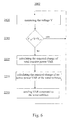
- the method 2000 of operating the wind farm 10 includes a step 2100 of determining the actual power consumption of the wind farm 10; and a subsequent step 2200 of adjusting the actual power production of the wind turbines such that the actual power production and actual power consumption of the wind farm 10 is balanced.
- the power consumption of the wind turbines fluctuates, e.g. due to required heating or cooling processes of the wind turbines or parts thereof.
- the steps 2100 and 2200 are in another aspect performed in a closed loop as indicated by the dashed line arrow of Fig. 4 to maintain the balanced state of the wind farm 10.
- a new power command or power instruction is issued at least to one of the wind turbines in step 2200 of each cycle if the actual power consumption of the wind farm 10 deviates from the actual power production.
- determining the actual power consumption of the wind farm 10 in step 2100 is based on measuring the actual electrical condition of the internal grid 200.
- Such a measurement can include measurements of frequency, currents and voltages of all phase lines and/or measurements of derived electrical values such as active power, reactive power or phase lags.
- the wind turbines typically regulate their set points themselves. Therefore the produced actual power of the wind farm 10 is known at any given time. If the power production and consumption of the wind farm 10 are balanced, the actual electrical condition of the internal grid 200, i.e. the frequency and/or voltage and/or current and/or phasing of all phase lines of the internal grid 200 matches expected values.
- rms voltages and frequency should be constant; and currents and phasing should match values that can be calculated from actual voltages and actual produced active and reactive power. Any deviation of the actual electrical condition of the internal grid 200 from expected values such as frequency or voltage shift can be used to calculate the actual active and actual reactive power consumption. This will be explained in more detail below.
- the actual power consumption of the wind farm 10 can be calculated from known or measured actual power consumption of all wind turbines and the other electricity consumers with variable power consumption of the wind farm 10. In an example, all wind turbines measures their actual power consumption and send the measured values to the central controller 500.
- the method 2001 of operating the wind farm 10 in a state of balanced power production and power consumption performs a closed-loop droop compensation based upon measuring the frequency of the internal grid 200.
- the internal grid frequency f is measured using e.g. the sensor 600 shown in Fig. 1 .
- the internal grid frequency f is compared with two reference frequencies f ref1 and f ref2 which are close but lower and higher than the required internal grid frequency of e.g. 50 Hz or 60 Hz, respectively.
- the actual total power production and actual total consumption of the wind farm 10 are substantially equal or balanced and in the next time step the measuring step 2110 will again be carried out. Otherwise, the change of total power production which is required to match the actual power consumption is calculated in step 2220. If the grid frequency f is lower than f ref1 , the total power production has to be increased. If the grid frequency f is higher than f ref2 , the total power production has to be decreased. As known to those skilled in the art the required change of total produced power also depend on the actual total power consumption and actual total production, respectively. The actual total power production of the wind farm 10 is, however, known since the power production of the wind turbines is controlled within the loop.
- step 2230 the required change of total power output is calculated for the individual wind turbines in a step 2230.
- Changing the power output of a wind turbine may also change its power consumption.
- This change of power consumption may also be taken into account in step 2230 e.g. by an iterative method based on a typical power consumption -power production characteristics or curve for the used wind turbines.
- the determined individual power set points are issued to the respective wind turbines in a step 2250.
- Fig. 6 illustrates a method for controlling the actual reactive power.
- a first step 2120 of a closed-loop cycle the internal grid voltage V is measured using e.g. the sensor 600 shown in Fig. 1 .
- the internal grid voltage V is compared with two reference values V ref1 and V ref2 which are close but lower and higher than the required internal grid voltage, respectively. If the grid voltage V is within the range of V ref1 and V ref2 the actual total reactive power production and actual total reactive power consumption of the wind farm 10 are substantially equal and in the next time step the measuring step 2120 will again be carried out. Otherwise, the change of total reactive power production which is required to match the actual reactive power consumption is calculated in step 2225.
- the required change of total reactive power is calculated for the individual wind turbines.
- the determined individual reactive power set points (VAR commands or instructions) are issued to the respective wind turbines in a step 2255.
- both the actual active and the actual reactive power are controlled such that they are in balance. This can e.g. be achieved if both methods 2001 and 2002 are carried out in parallel, e.g. as different threads or in a common loop. In this event neither active power nor reactive power has to be exchanged with the external grid 300. This enables operating of the wind farm 10 without an external grid 300.
- the wind farm 10 feeds electric energy into the external grid 300.
- the wind farm 10 is operated such the power production is at maximum at given wind condition.
- the central controller 500 can also regulate the active and/or reactive power flow according to external requests.
- the amount of power flow to the external grid 300 is typically measured at the point of common coupling (PCC) in the substation 400 using the sensor 601 shown in Fig. 1 .
- PCC point of common coupling
- all wind turbines of the wind farm 10 can remain connected to the internal grid 200 even if internal and external grids have to be disconnected. This is achieved by driving the wind farm 10 into and operating the wind farm 10 in a balanced state. Since the wind turbines are typically operating according to given set points of active and reactive power, the measurements at the PCC enables calculation of actual active power consumption and actual reactive power consumption of the wind farm 10 at any given time during normal operation with connected internal 200 and external grid 300. According to a further embodiment the method 2003 of operating the wind farm 10 in a state of balanced power production and power consumption performs in a step 2130 a voltage, V, and a current, I, measurement for each phase line using e.g. the sensor 600 shown in Fig. 1 .
- step 2205 This is followed by calculating the actual power, P, in a step 2205.
- the actual power is measured directly using a power meter in an alternative.
- the steps 2130 and 2205 are typically carried out several times per second during normal operation of the wind farm 10 as part of a closed loop control to ensure the externally requested power flow into the external grid 300.
- the actual power consumption of the wind farm 10 is calculated in a step 2207 from the difference of last measured power flow P and sum of current power set points of the wind turbines. This is followed by a step 2200 of calculating the required total power output to match the calculated actual power consumption of the wind farm 10.
- step 2230 the required power outputs of the wind turbines are determined in a step 2230 such that their sum is equal to the total power output of the wind farm 10 obtained in step 2220.
- steps 2205, 2207, 2220 and 2230 are typically carried out both for active and reactive power. Accordingly, in step 2250 corresponding VAR commands or instructions are additionally issued to the wind turbines.
- all wind turbines can remain connected to the internal grid 200. Further all basic system functions, i.e. lubrication, heating, cooling and all control and monitoring functions, of all wind turbines can be maintained. In other words, the wind turbines can be maintained in a state of function standby which allows an immediate start up of the wind turbine later on. This means that instead of disconnecting the individual wind turbines from the internal grid 200 the complete wind farm 10 is separated and can remain functional. Thereby, the wind farm 10 is islanded in a controlled way and the emergency shut down of the wind farm 10 can be avoided during an outage of the external grid 300. This has at least two major advantages. On the one hand, emergency shut downs are accompanied by emergency braking of the wind turbines.
- the wind farm 10 can further include an ac or dc energy storage system (not shown in Fig. 1 ) for buffering electrical energy and/or currents of the internal grid 200.
- the method for operating the wind farm 10 in a balanced state includes a step of buffering electrical energy of the internal grid 200.
- Such an electrical buffering system can include a battery, a magnetic energy storage such as a superconducting device, a flywheel device, capacitors or a combination thereof which are e.g. connected in parallel to the wind turbines.
- the energy storage system is typically coupled to the internal grid 200 using a frequency inverter (not shown in Fig.
- flywheels store kinetic energy in a rapidly rotating mass of the rotor. In particular, if the rotor is magnetically levitated huge amounts of energy can be stored at high rotating speed. Supercapacitors and flywheels can be charged and can release their energy within seconds; superconducting coils can take up and provide megawatts of power almost instantaneously with efficiency close to 100%. Reactive and/or active power compensation systems are particularly useful in case of disconnecting internal 200 and external 300 grid.
- the total power output of the wind farm 10 has to be reduced to the amount balancing the actual total power consumption of the wind farm 10 within a few ten ms. This can required steep down ramping rates of the wind turbines.
- the terms of ramping up and down a wind turbine refer to increasing and decreasing the power output of the wind turbine, respectively.
- the rates for ramping down the wind turbines can be reduced if a part of the produced active and/or reactive power can be stored in a temporary buffer system. The buffered energy may be fed back into the external grid 300 after its recovery.
- the wind farm 10 is, in a first step 1300, disconnected from the external grid 300 and ramped down such that actual power consumption and actual power production are matched. This can e.g. be achieved as has already been explained with reference to Fig. 7 .
- a subsequent step 2000 the wind farm 10 is maintained in the balanced state using e.g. the methods 2001 and/or 2002.
- the step 2000 is typically carried out in a closed loop as indicated by the dashed-line arrow in Fig. 8 . All wind turbines can remain connected to the internal grid 200 but at least a part of the wind turbines has to be ramped down. After recovery of the external grid 300 the wind turbines need not to be restarted and heated up. Only the internal 200 and external grid 300 have to be synchronized and reconnected; and the wind turbines have to be ramped up again.
- the wind farm 10 will be able to feed again power into the external grid 300 with a much shorter delay after external grid recovery compared to the event of disconnecting all wind turbines from the internal grid 200 and shutting them down completely.
- a wind turbine has typically to be started very slowly if the external temperature is low, in the extreme case over a matter of hours, in order to allow thereby a very uniform heating of all constituents before the wind turbine can provide full power.
- the minimum power output of a wind turbine may be limited, i.e. operation of a wind turbine at power level between a minimum value and 0 % may not be possible.
- the power output of each wind turbine can be reduced down to a few %, e.g. to 1% or 5% of full power in a linear manner.
- the total power output of the wind farm 10 can typically be reduced from 100 % to a few %, e.g. to 1% or 5% of rated full capacity in a linear manner too.
- the total power consumption of the wind turbines and the other electricity consumers of the wind farm 10 like sensors, the transformer substation 400 and the central controller 500 may be below the minimum amount of power the wind farm 10 can produce if all wind turbines deliver electrical power.
- one or a part of the wind turbines are, therefore, set to consume energy only.
- those wind turbines are issued to produce no power, i.e. they are controlled to ramp down to zero power production in a step 1500 as shown in Fig. 9 .
- all wind turbines can remain connected to the internal grid 200 and all system functions of all wind turbines can be maintained.
- a parallel step 2005 of controlling power production and consumption without changing power values of the down ramping wind turbines ensures that the wind farm 10 is maintained in the balanced state. This can again be achieved using the methods 2001 and/or 2002 but without changing the power set points of the down ramping or down ramped wind turbines.
- the step 2005 is again typically carried out in a closed loop. Ramping down a part of the wind turbines in a wind farm 10 can also be advantageous during an outage of the external grid 300. In such an event only a part, e.g. two, of the wind turbines are typically scheduled to produce power, whereas the remaining wind turbines are set to produce no power in the step 2250 of the method 2003 of Fig. 7 .
- one wind turbine may be enough to provide enough power for maintaining the system functions of the remaining wind turbines and to feed the other electrical consumers of the wind farm 10.
- at least two wind turbines may be used to produce power as fluctuating wind conditions can be better balanced with two wind turbines.
- one or a part of the wind turbines are set to produce only reactive power to compensate the actual reactive power consumption of the active power producing wind turbines and other consumers of the internal grid 200 such as the transformers.
- a part of the wind turbines of the wind farm 10 may be stopped completely. This will reduce wear in the event of a longer lasting outage of the external grid 300.
- the wind farm 10 can further include an additional ac or dc power source 900, such as of a fuel power source, a battery-based power source or a solar power source.
- the additional power source 900 may be coupled to the internal grid 200 using a frequency inverter (not shown) to convert the power flow between the fixed frequency ac of the internal grid 200 and the additional power source.
- the method for operating the wind farm 10 in a balanced state includes a step 1200 of synchronizing the additional power source 900 with and connecting the additional power source 900 to the internal grid 200. As illustrated in Fig.
- step 2006 a closed loop control for balancing actual power production and actual power consumption of the wind farm 10 is carried out.
- a 100 kW diesel aggregate is used as additional power source 900.
- the diesel aggregate is switched on and synchronized without feeding power into the internal grid 200. Synchronization includes matching voltage, frequency and phases and can e.g. be done by regulating the generator speed through an engine governor e.g. by using an auto-synchronizer. After synchronization the diesel aggregate can be connected to the internal grid 200.
- the produced power of the diesel aggregate is increased in the loops of step 2006 such that power production of the wind turbines and the diesel aggregate matches the power consumption of the wind farm.
- This can e.g. be achieved using a method which is similar to the method 2005 of Fig. 9 but takes into account the increasing power output of the diesel aggregate in step 2006 of each cycle.
- the method for operating the wind farm 10 in a balanced state may includes a further step of ramping down all wind turbines together, in groups or one by one. All wind turbines can remain connected to the internal grid in a state of function standby wherein all system functions of the wind turbines are maintained. This will allow maintenance work e.g. during an outage of the external grid 300 and a fast reconnecting of the wind farm 10 after recovery of the external grid 300.
- a part of the wind turbines or all wind turbines of the wind farm 10 may be stopped completely i.e. shut off. In the event of an expected longer lasting outage of the external grid 300 this will allow saving of fuel or energy and reduces wear.
- Fig. 11 still another aspect will be explained.
- a closed loop control step 2000 of matching actual power production and actual power consumption but without changing the power set points of the starting wind turbine is carried out to maintain the wind farm 10 in the balanced state. This can e.g. be achieved using the methods 2001 and/or 2002.
- the step 2000 is again typically carried out in a closed loop as indicated by the dashed line arrow.
- an additional power source 900 like a diesel aggregate which is connected to the internal grid 200 is used to restart a first wind turbine. After synchronizing the first wind turbine it is connected to the internal grid 200. After synchronizing one, a few or all wind turbines, the additional power source 900 can ramped down again and eventually switched off. To balance power production and power consumption at least one wind turbine is ramped up in parallel. Finally, the internal grid 200 and external 300 grid are synchronized after recovery of the external grid 300 and all wind turbines can be ramped up to produce full power or the externally requested amount of total power again.
- a wind farm control system 5000 includes a communication device 5100 which is adapted to r transmit set points such as power commands or power generating instructions to the wind turbines 100 - 102 of the wind farm 10. Typically, the communication device 5100 is also adapted to receive set points and/or data and/or commands from the wind turbines.
- the wind farm control system 5000 further includes a controller 5200 which is adapted to determine the actual power consumption and actual power balance of the wind farm 10. Further, the controller 5200 is configured to determine power orders or power generating instructions for the wind turbines 100 - 102 of the wind farm 10.
- the wind farm control system 5000 is arranged for controlling the wind farm 10 in a balanced state of substantially equal power consumption and power production.
- the wind farm control system 5000 is in particular operable to execute any of the above described methods for operating the wind farm 10 in a balanced state.
- the actual power consumption of the wind farm 10 can be determined from parameters characterizing the actual electrical condition of the internal grid 200, such as grid voltage and/or frequency and /or power flow.
- the controller 5200 includes a frequency sensor and/or a voltage sensor and/or a current sensor and/or a power sensor 600 for determining the actual electrical condition of the internal grid 200; and a processor adapted to calculate the power balance of the wind farm 10 and to determine power orders or power generating instructions for each of the wind turbines 100 - 102.
- the wind farm control system 5000 may also take into account power consumption values measured by the individual wind turbines 100 - 102 and other power consumers within the internal grid 200 for calculating the total power consumption of the wind farm 10. For power consumers with predictable consumption such as transformers, capacitors or the like measurement of consumption may be replaced by calculations based on respective electric models.
- both active and reactive power production of the wind farm 10 are balanced to the active and reactive power consumption by the wind farm control system 5000.
- the communication device 5100 of the wind farm control system 5000 is typically operable to transmit power set points to and receive data and/or instructions from an additional power source 900 and/or an energy storage device and/or further sensors and/or actuators.
- the wind farm control system 5000 includes a sensor 602 for measuring the actual electrical condition of the external grid 300. This enable the wind farm control system 5000 to detect an outage or an under voltage and/or under frequency condition of the external grid 300. In such an event the wind farm control system 5000 can independently disconnect the internal 200 and the external grid 300 and operate the wind farm 10 in a balanced state. Thereby, the wind farm 10 is islanded in a controlled way and the emergency shut down of the wind farm 10 can be avoided during an outage of the external grid 300. Further, the external grid 300 can rapidly be stabilized in the event of a detected under voltage and/or under frequency condition of the external grid 300. After recovery or stabilizing of the external grid 300, the internal grid 200 can be synchronized with and be reconnected to the external grid 300 with minimum delay as all basic system functions of the wind turbines 100 - 102 can be maintained during the controlled islanding of the wind farm 10.
- the central wind farm controller 500 described with reference to Fig. 2 operates as controller 5200.
- these functions are provided by one of the wind turbines 100 - 102.
- the hardware of the turbine controller 150 of the supervising wind turbine must be powerful enough to run the additional software or computer program code related to the wind farm control system 5000.
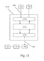
- the program 5010 includes a computer program code module 5310 for receiving and evaluating or pre-processing the data from the sensors 600 of the wind farm control system 5000. Further, the module 5310 may additionally include computer code for transmitting data to sensors 600 and /or actuators 700. Typically, the module 5310 runs on a multifunction relay which transduces and digitizes data of the sensors and communicates the results over the CAN-bus 560 to a computer program code module 5210. Alternatively and or additionally the module 5210 receives via the Ethernet network or bus 560 measured power consumption e.g. from the wind turbines 100 - 102.
- the module 5210 calculates the actual power balance of the wind farm 10 and determines power orders for the wind turbines 100 - 102 such that the actual power production and actual power consumption of the wind farm 10 are balanced. Typically, the module 5210 carries out these calculations for both active and reactive power.
- the computer program 5010 further includes a program code module 5110 to transmit power and or VAR orders or instructions to the wind turbines 100 via the Ethernet bus 560. Further, the module 5210 may determine instructions for additional devices like power switches 700, energy storage devices, additional power devices 900 or the like. Theses instructions are typically transmitted via the CAN- or the Ethernet- bus too.
- the computer program code modules 5110 and 5210 run typically on a single computer, e.g. in one of the wind turbines 100 or on the central controller 500 of the wind farm 10.
- the computer program 5010 is a real time program. This allows fast reliable balancing of the power production and consumption of the wind farm 10 and reduces the requirements on the energy buffer capability of the wind farm 10 and/or on the hardware tolerances against power fluctuations.
Abstract
Description
- A method for operating a wind farm in a state of balanced power production and consumption is disclosed herein. Further, a control system for balancing the power production and consumption of a wind farm is disclosed herein.
- According to a first aspect of the present invention, method for operating a wind farm which includes a wind farm control system and at least two wind turbines is provided. The at least two wind turbines are connected via an internal grid. According to an aspect, the method includes a step of determining the actual power consumption of the wind farm; and a step of adjusting the actual power production of at least on of the wind turbines so that the actual power production and actual power consumption of the wind farm are substantially equal.
- Further, a method for operating a wind farm which includes a wind farm control system and several power sources, which are connected via an internal grid, is provided. At least two of the power sources are wind turbines and at least one power source is selected from a group consisting of a fuel power source, a battery-based power source and a solar power source. According to another aspect, the method includes a step of determining the actual power consumption of the wind farm; and a step of adjusting the actual power production of at least on of the power sources so that the power actual production and actual power consumption of the wind farm are substantially equal.
- In yet another aspect, a wind farm control system is provided which is arranged for controlling the wind farm in state, in which the actual power production and actual power consumption of the wind farm are substantially equal. The wind farm control system includes a controller which is adapted to determine the actual power consumption and actual power balance of the wind farm and to determine power generation instructions for the wind turbines. The wind farm control system further includes a communication device which is adapted to transmit power generation instructions to each of the wind turbines of the wind farm.
- Further aspects, advantages and features are apparent from the dependent claims, the description and the accompanying drawings, in which:
-
Fig. 1 shows a schematic illustration of a wind farm wherein aspects of the present technique are applicable. -
Fig. 2 shows a scheme of a central controller as used in several embodiments. -
Fig. 3 illustrates the functional components of an exemplary wind turbine as used in several embodiments. -
Fig. 4 shows a flow diagram of a method for operating a wind farm according to an embodiment. -
Fig. 5 shows a flow diagram of a method for operating a wind farm which is based upon measuring of internal grid frequency according to another embodiment. -
Fig. 6 shows a flow diagram of a method for operating a wind farm which is based upon measuring of internal grid voltage according to yet another embodiment. -
Fig. 7 shows a flow diagram of a method for operating a wind farm which is based upon measuring of internal grid voltage and current according to still another embodiment. -
Fig. 8 shows a flow diagram of a method for operating a wind farm according to yet another embodiment. -
Fig. 9 shows a flow diagram of a method for operating a wind farm according to still an embodiment. -
Fig. 10 shows a flow diagram of a method for operating a wind farm according to yet another embodiment. -
Fig. 11 shows a flow diagram of a method for operating a wind farm according to still another embodiment. -
Fig. 12 shows a scheme of a control system according to an embodiment. -
Fig. 13 shows a diagram of computer program modules and flow of information for controlling a wind farm as used in several embodiments. - Reference will now be made in detail to the various embodiments of the invention, one or more examples of which are illustrated in the figures. Each example is provided by way of explanation of the invention, and is not meant as a limitation. For example, features illustrated or described as part of one embodiment can be used on or in conjunction with other embodiments to yield yet a further embodiment. It is intended that such modifications and variations are included herewith.
- In
Fig. 1 a schematic illustration of awind farm 10 is shown. Twowind turbines internal grid 200 with atransformer substation 400 usingfeeders 700. The power produced by thewind turbines turbine transformers 450 before being coupled to theinternal grid 200. Theinternal grid 200 is typically a medium voltage, three-phase alternating current (ac) network operating e.g. at a few kV up to a few 10 kV and 50 Hz or 60 Hz. Astation transformer 451 of thetransformer substation 400 is typically used to step up voltage from the internal grid voltage to a required transmission voltage of the external, main orutility grid 300 to which thetransformer substation 400 can be connected at the point-of-common-coupling (PCC) using asuitable power switch 701. Further, theinternal grid 200 powers acentral controller 500 and thewind turbines transformers central controller 500 is arranged for communication with thewind turbines communication links 550, which may be implemented in hardware and/or software. Further, thecentral controller 500 may be configured to communicate via thecommunication links 550 with anadditional power source 900, such as a small (e.g. 100 kW) diesel aggregate, which may be connected in addition to theinternal grid 200. Typically, thecommunication links 550 are realized as an Ethernet LAN which will also enable remote control using a SCADA (Supervisory, Control and Data Acquisition)computer 800. However, thecommunication links 550 may also be configured to remotely communicate data signals to and from thecentral controller 500 in accordance with any fiber optic, wired or wireless communication network known to one skilled in the art. Such data signals may include, for example, signals indicative of operating conditions of individual wind turbine which are transmitted to thecentral controller 500 and various command signals communicated by thecentral controller 500 to thewind turbines central controller 500 is further in communication with theinternal grid 200 and the external grid viasensors 600 to 602, such as voltage, current, frequency, power sensors or the like. Note that each of thesensors 600 to 602 may represent different sensors, e.g. for each phase line. Further, thecentral controller 500 is typically operable to control various switching devices or actuators, such asfeeders 700,power switches communication links 560 to control e.g. frequency, active and reactive power output of thewind farm 10. In an ac electric system the current, I, and the voltage, V, can be out of phase. Consequently, the product of current and voltage S=I*V can be complex. In the context of this application, the term power refers to the active or real power P=Re(S), i.e. to the energy that is transferred per unit of time. In contrast, the imaginary part of S is referred to as reactive power Q=Im(S) within the context of this application. Typically, thecommunication links 560 are realized as a CAN (Controller Area Network) - bus. Again, thecommunication links 560 may also be configured to remotely communicate data signals to and from thecentral controller 500 in accordance with any fiber optic, wired or wireless communication network known to those skilled in the art. Note, that the dashed and dashed-dotted lines inFig. 1 only indicate that there are links between thecentral controller 500 and the other devices. They do not necessarily reflect the topology of the usedcommunication links -
Fig. 2 shows a scheme of thecentral controller 500 which operates as a supervisory control of thewind farm 10. Thecentral controller 500 communicates with each wind turbine 100 - 102 located in thewind farm 10 and typically performs a closed loop control or regulation such that thewind farm 10 produces active and reactive power according to given request or global set points of thewind farm 10. It should be understood, that the term "control" can also refer to "regulate" or "regulation". Typically, thecentral controller 500 reads the actual reactive power and actual (real or active) power at the PCC; compares the measured values with the global set points and issues power and VAR (voltage-ampere-reactive) commands or set points to each wind turbine 100-102 on any deviation. This effectively makes thewind farm 10 acts as a single power production unit instead of individual wind turbines 100-102. For example, thecentral controller 500 may receive global set points for the total active and reactive power to be fed into or received from theexternal grid 300 from a control centre (not shown) of the external grid or the SCADA computer via an EthernetLAN 550. For this purpose thecentral controller 500 includes acommunication device 510, i.e. an Ethernet LAN controller and suitable computer program code which receives the global set point information and transfers them to a processing and storage unit, e.g. aprocessor 520. Further, aninterface 530 tosensors 600 andactuators 701 of thecentral controller 500 receives via aCAN bus 560 current and voltage data fromsensors 600 which are also transferred to the processing andstorage unit 520. Typically, theinterface 530 includes a multifunction relay (MFR). The processing andstorage unit 520 and thecommunication device 510 can e.g. be formed by acomputer 540 equipped with an Ethernet interface and a CAN-bus interface to communicate with the MFR. After calculating individual set points for the wind turbines 100-102 in the processing andstorage unit 520 such that the global set points of power flow are met, the corresponding set points are distributed to the individual wind turbines 100-102 via the Ethernet 550. Further commands may be issued via the CAN-bus topower switches 701 and/or capacitors (not shown) and reactors (not shown) to adjust active and reactive power to the requested values. Note thatFig. 2 shows, for sake of simplicity, only three wind turbines 100-102. Large wind farms can have more than hundred wind turbines controlled by onecentral controller 500 which is typically located in a substation but it may also be part of one of the wind turbines. -
Fig. 3 illustrates the functional components of anexemplary wind turbine 100. In the context of this application, the term wind turbine refers to a machine that converts the kinetic energy of wind into mechanical energy and the mechanical energy into electrical energy using a synchronous or an asynchronous generator. Thewind turbine 100 includes aturbine rotor 110, having for exemplification threerotor blades 115, which drives theelectrical generator 120. Thewind turbine 100 may further have a gearbox (not shown) between theturbine rotor 110 and thegenerator rotor 125. Thegenerator 120 includes agenerator stator 130 having windings (not shown) coupled to theinternal grid 200 and agenerator rotor 125 having windings (not shown) coupled to apower converter 160, such as the shown variable frequency inverter. Thepower converter 160 is configured to control the torque produced by the generator by adjusting the excitation voltage to the rotor windings. By controlling the frequency delivered to thegenerator rotor 125 it is also possible to keep the frequency of the power output of the generator on a stable level independently of the turning speed of thegenerator rotor 125. The excitation provided by thepower converter 160 is based on a torque command and a frequency command transmitted by aturbine controller 150. Theturbine controller 150 may include a programmable logic controller (PLC) or a computer operable to implement a torque control algorithm and a frequency control algorithm to ensure a fixed frequency output of required power at variable speed of thegenerator rotor 125. As known to those skilled in the art, power output of the generator is the product of generator speed and generator torque. Theturbine controller 150 typically checks the speed of thegenerator rotor 125 several times per second using asensor 603. Accordingly, if speed is known the torque can be adjusted to maintain the power set points obtained from thecentral controller 500 via theEthernet LAN 550. Theturbine controller 150 can also be operable to control the speed of thegenerator rotor 125 via regulation of pitch of therotor blades 115. If the speed of thegenerator rotor 125 becomes too high or too low, it sends an order to the blade pitch mechanism (not shown) which turns therotor blades 115 out of and back into the wind, respectively. Further, thewind turbine 100 may be equipped with asensor 604 measuring e.g. the power, voltage, and /or current output of thegenerator 120. Note that the variablespeed wind turbine 100 equipped with a doubly fedinduction generator 120 is shown inFig. 3 only for exemplification. Any other wind turbine capable of receiving electrical set points such as active and/or reactive power and/or voltage and/or frequency from a supervisory controller and performing a closed loop control at least of the produced active power can be used in the embodiments explained below. The wind turbines may be constant or variable speed and directly or indirectly, i.e. via a frequency inverter converting the variable frequency ac produced by the generator to a fixed frequency ac of theinternal grid 200, coupled to theinternal grid 200. One advantage of the doubly fedinduction generator 120 consists in its ability to provide both active and reactive power to theinternal grid 200. - With respect to
Fig. 4 , a method for operating thewind farm 10 in a balanced state, e.g. in a state wherein the actual (total) power production and actual (total) power consumption of thewind farm 10 is substantially equal, is described. According to a first aspect, themethod 2000 of operating thewind farm 10 includes astep 2100 of determining the actual power consumption of thewind farm 10; and asubsequent step 2200 of adjusting the actual power production of the wind turbines such that the actual power production and actual power consumption of thewind farm 10 is balanced. Typically, the power consumption of the wind turbines fluctuates, e.g. due to required heating or cooling processes of the wind turbines or parts thereof. Therefore, thesteps Fig. 4 to maintain the balanced state of thewind farm 10. Typically, a new power command or power instruction is issued at least to one of the wind turbines instep 2200 of each cycle if the actual power consumption of thewind farm 10 deviates from the actual power production. - According to yet another aspect, determining the actual power consumption of the
wind farm 10 instep 2100 is based on measuring the actual electrical condition of theinternal grid 200. Such a measurement can include measurements of frequency, currents and voltages of all phase lines and/or measurements of derived electrical values such as active power, reactive power or phase lags. As has been explained with reference toFig. 2 , the wind turbines typically regulate their set points themselves. Therefore the produced actual power of thewind farm 10 is known at any given time. If the power production and consumption of thewind farm 10 are balanced, the actual electrical condition of theinternal grid 200, i.e. the frequency and/or voltage and/or current and/or phasing of all phase lines of theinternal grid 200 matches expected values. In particular, rms voltages and frequency should be constant; and currents and phasing should match values that can be calculated from actual voltages and actual produced active and reactive power. Any deviation of the actual electrical condition of theinternal grid 200 from expected values such as frequency or voltage shift can be used to calculate the actual active and actual reactive power consumption. This will be explained in more detail below. Alternatively and/or additionally, the actual power consumption of thewind farm 10 can be calculated from known or measured actual power consumption of all wind turbines and the other electricity consumers with variable power consumption of thewind farm 10. In an example, all wind turbines measures their actual power consumption and send the measured values to thecentral controller 500. - With respect to
Fig. 5 yet another aspect will be explained. Themethod 2001 of operating thewind farm 10 in a state of balanced power production and power consumption performs a closed-loop droop compensation based upon measuring the frequency of theinternal grid 200. In afirst step 2110 of each cycle the internal grid frequency f is measured using e.g. thesensor 600 shown inFig. 1 . In asubsequent step 2210 the internal grid frequency f is compared with two reference frequencies fref1 and fref2 which are close but lower and higher than the required internal grid frequency of e.g. 50 Hz or 60 Hz, respectively. If the internal grid frequency f is within the range of fref1 and fref2 the actual total power production and actual total consumption of thewind farm 10 are substantially equal or balanced and in the next time step the measuringstep 2110 will again be carried out. Otherwise, the change of total power production which is required to match the actual power consumption is calculated instep 2220. If the grid frequency f is lower than fref1, the total power production has to be increased. If the grid frequency f is higher than fref2, the total power production has to be decreased. As known to those skilled in the art the required change of total produced power also depend on the actual total power consumption and actual total production, respectively. The actual total power production of thewind farm 10 is, however, known since the power production of the wind turbines is controlled within the loop. Next the required change of total power output is calculated for the individual wind turbines in astep 2230. Changing the power output of a wind turbine may also change its power consumption. This change of power consumption may also be taken into account instep 2230 e.g. by an iterative method based on a typical power consumption -power production characteristics or curve for the used wind turbines. At the end of the cycle the determined individual power set points are issued to the respective wind turbines in astep 2250. - With respect to
Fig. 6 still another aspect will be explained. It illustrates a method for controlling the actual reactive power. In afirst step 2120 of a closed-loop cycle the internal grid voltage V is measured using e.g. thesensor 600 shown inFig. 1 . In asubsequent step 2215 the internal grid voltage V is compared with two reference values Vref1 and Vref2 which are close but lower and higher than the required internal grid voltage, respectively. If the grid voltage V is within the range of Vref1 and Vref2 the actual total reactive power production and actual total reactive power consumption of thewind farm 10 are substantially equal and in the next time step the measuringstep 2120 will again be carried out. Otherwise, the change of total reactive power production which is required to match the actual reactive power consumption is calculated instep 2225. If the grid voltage V is lower than Vref1, the total reactive power production has to be increased. If the grid voltage V is higher than Vref2, the total reactive power production has to be decreased. As known to those skilled in the art the required change of total reactive power also depends on the known, currently produced total reactive power. In asubsequent step 2235 the required change of total reactive power output is calculated for the individual wind turbines. At the end of the cycle the determined individual reactive power set points (VAR commands or instructions) are issued to the respective wind turbines in astep 2255. - In still another aspect, both the actual active and the actual reactive power are controlled such that they are in balance. This can e.g. be achieved if both
methods external grid 300. This enables operating of thewind farm 10 without anexternal grid 300. - During normal operation the
wind farm 10 feeds electric energy into theexternal grid 300. Typically, thewind farm 10 is operated such the power production is at maximum at given wind condition. Thecentral controller 500 can also regulate the active and/or reactive power flow according to external requests. The amount of power flow to theexternal grid 300 is typically measured at the point of common coupling (PCC) in thesubstation 400 using thesensor 601 shown inFig. 1 . In an event of an outage of theexternal grid 300 all wind turbines are usually disconnected from theinternal grid 200 and a fast emergency shut down of all wind turbines of thewind farm 10 is usually carried out. Note that this can also be necessary if the frequency and/or voltage of theexternal grid 300 exceeds certain thresholds. As will be explained with respect toFig. 7 , all wind turbines of thewind farm 10 can remain connected to theinternal grid 200 even if internal and external grids have to be disconnected. This is achieved by driving thewind farm 10 into and operating thewind farm 10 in a balanced state. Since the wind turbines are typically operating according to given set points of active and reactive power, the measurements at the PCC enables calculation of actual active power consumption and actual reactive power consumption of thewind farm 10 at any given time during normal operation with connected internal 200 andexternal grid 300. According to a further embodiment themethod 2003 of operating thewind farm 10 in a state of balanced power production and power consumption performs in a step 2130 a voltage, V, and a current, I, measurement for each phase line using e.g. thesensor 600 shown inFig. 1 . This is followed by calculating the actual power, P, in astep 2205. Instead of measuring currents and voltages the actual power is measured directly using a power meter in an alternative. Thesteps wind farm 10 as part of a closed loop control to ensure the externally requested power flow into theexternal grid 300. In the event of disconnecting internal 200 andexternal grid 300, e.g. due to an outage of theexternal grid 300, the actual power consumption of thewind farm 10 is calculated in astep 2207 from the difference of last measured power flow P and sum of current power set points of the wind turbines. This is followed by astep 2200 of calculating the required total power output to match the calculated actual power consumption of thewind farm 10. Afterwards, the required power outputs of the wind turbines are determined in astep 2230 such that their sum is equal to the total power output of thewind farm 10 obtained instep 2220. Note that thesteps step 2250 corresponding VAR commands or instructions are additionally issued to the wind turbines. - In doing so, all wind turbines can remain connected to the
internal grid 200. Further all basic system functions, i.e. lubrication, heating, cooling and all control and monitoring functions, of all wind turbines can be maintained. In other words, the wind turbines can be maintained in a state of function standby which allows an immediate start up of the wind turbine later on. This means that instead of disconnecting the individual wind turbines from theinternal grid 200 thecomplete wind farm 10 is separated and can remain functional. Thereby, thewind farm 10 is islanded in a controlled way and the emergency shut down of thewind farm 10 can be avoided during an outage of theexternal grid 300. This has at least two major advantages. On the one hand, emergency shut downs are accompanied by emergency braking of the wind turbines. This is a high load for the wind turbines that may limit their life time. On the other hand, it can take a long time (up to days under extreme cold weather conditions) to heat up the systems of the wind turbines again and to bring them back to service after recovery of theexternal grid 300. - The
wind farm 10 can further include an ac or dc energy storage system (not shown inFig. 1 ) for buffering electrical energy and/or currents of theinternal grid 200. In still another aspect, the method for operating thewind farm 10 in a balanced state includes a step of buffering electrical energy of theinternal grid 200. Such an electrical buffering system can include a battery, a magnetic energy storage such as a superconducting device, a flywheel device, capacitors or a combination thereof which are e.g. connected in parallel to the wind turbines. The energy storage system is typically coupled to theinternal grid 200 using a frequency inverter (not shown inFig. 1 ) converting the power and/or current flow between the fixed frequency ac of theinternal grid 200 and the frequency used in the energy storage system. Flywheels store kinetic energy in a rapidly rotating mass of the rotor. In particular, if the rotor is magnetically levitated huge amounts of energy can be stored at high rotating speed. Supercapacitors and flywheels can be charged and can release their energy within seconds; superconducting coils can take up and provide megawatts of power almost instantaneously with efficiency close to 100%. Reactive and/or active power compensation systems are particularly useful in case of disconnecting internal 200 and external 300 grid. Note, that in the event of an outage of theexternal grid 300 the total power output of thewind farm 10 has to be reduced to the amount balancing the actual total power consumption of thewind farm 10 within a few ten ms. This can required steep down ramping rates of the wind turbines. In the context of this application, the terms of ramping up and down a wind turbine refer to increasing and decreasing the power output of the wind turbine, respectively. The rates for ramping down the wind turbines can be reduced if a part of the produced active and/or reactive power can be stored in a temporary buffer system. The buffered energy may be fed back into theexternal grid 300 after its recovery. - With reference to
Fig. 8 yet another aspect will be explained. Accordingly, thewind farm 10 is, in afirst step 1300, disconnected from theexternal grid 300 and ramped down such that actual power consumption and actual power production are matched. This can e.g. be achieved as has already been explained with reference toFig. 7 . In asubsequent step 2000 thewind farm 10 is maintained in the balanced state using e.g. themethods 2001 and/or 2002. Thestep 2000 is typically carried out in a closed loop as indicated by the dashed-line arrow inFig. 8 . All wind turbines can remain connected to theinternal grid 200 but at least a part of the wind turbines has to be ramped down. After recovery of theexternal grid 300 the wind turbines need not to be restarted and heated up. Only the internal 200 andexternal grid 300 have to be synchronized and reconnected; and the wind turbines have to be ramped up again. - Thus, the
wind farm 10 will be able to feed again power into theexternal grid 300 with a much shorter delay after external grid recovery compared to the event of disconnecting all wind turbines from theinternal grid 200 and shutting them down completely. Note that a wind turbine has typically to be started very slowly if the external temperature is low, in the extreme case over a matter of hours, in order to allow thereby a very uniform heating of all constituents before the wind turbine can provide full power. - The minimum power output of a wind turbine may be limited, i.e. operation of a wind turbine at power level between a minimum value and 0 % may not be possible. Typically, the power output of each wind turbine can be reduced down to a few %, e.g. to 1% or 5% of full power in a linear manner. Accordingly, the total power output of the
wind farm 10 can typically be reduced from 100 % to a few %, e.g. to 1% or 5% of rated full capacity in a linear manner too. Particularly for large (MW producing) wind turbines, the total power consumption of the wind turbines and the other electricity consumers of thewind farm 10 like sensors, thetransformer substation 400 and thecentral controller 500 may be below the minimum amount of power thewind farm 10 can produce if all wind turbines deliver electrical power. In another embodiment, one or a part of the wind turbines are, therefore, set to consume energy only. In other words, those wind turbines are issued to produce no power, i.e. they are controlled to ramp down to zero power production in astep 1500 as shown inFig. 9 . Again, all wind turbines can remain connected to theinternal grid 200 and all system functions of all wind turbines can be maintained. Aparallel step 2005 of controlling power production and consumption without changing power values of the down ramping wind turbines ensures that thewind farm 10 is maintained in the balanced state. This can again be achieved using themethods 2001 and/or 2002 but without changing the power set points of the down ramping or down ramped wind turbines. Thestep 2005 is again typically carried out in a closed loop. Ramping down a part of the wind turbines in awind farm 10 can also be advantageous during an outage of theexternal grid 300. In such an event only a part, e.g. two, of the wind turbines are typically scheduled to produce power, whereas the remaining wind turbines are set to produce no power in thestep 2250 of themethod 2003 ofFig. 7 . - Even one wind turbine may be enough to provide enough power for maintaining the system functions of the remaining wind turbines and to feed the other electrical consumers of the
wind farm 10. However, even in this event at least two wind turbines may be used to produce power as fluctuating wind conditions can be better balanced with two wind turbines. - In a further example, one or a part of the wind turbines are set to produce only reactive power to compensate the actual reactive power consumption of the active power producing wind turbines and other consumers of the
internal grid 200 such as the transformers. In still a further example, a part of the wind turbines of thewind farm 10 may be stopped completely. This will reduce wear in the event of a longer lasting outage of theexternal grid 300. - As has already been explained with reference to
Fig. 1 , thewind farm 10 can further include an additional ac ordc power source 900, such as of a fuel power source, a battery-based power source or a solar power source. Further, theadditional power source 900 may be coupled to theinternal grid 200 using a frequency inverter (not shown) to convert the power flow between the fixed frequency ac of theinternal grid 200 and the additional power source. According to yet a further aspect, the method for operating thewind farm 10 in a balanced state includes astep 1200 of synchronizing theadditional power source 900 with and connecting theadditional power source 900 to theinternal grid 200. As illustrated inFig. 10 , this is followed by astep 2006 in which a closed loop control for balancing actual power production and actual power consumption of thewind farm 10 is carried out. Those skilled in the art will appreciate, that any of the above mentioned methods for operating the wind farm in a balanced state can be modified such that the produced power of theadditional power source 900 is additionally taken into account. In the following example a 100 kW diesel aggregate is used asadditional power source 900. In thestep 1200 the diesel aggregate is switched on and synchronized without feeding power into theinternal grid 200. Synchronization includes matching voltage, frequency and phases and can e.g. be done by regulating the generator speed through an engine governor e.g. by using an auto-synchronizer. After synchronization the diesel aggregate can be connected to theinternal grid 200. Than the produced power of the diesel aggregate is increased in the loops ofstep 2006 such that power production of the wind turbines and the diesel aggregate matches the power consumption of the wind farm. This can e.g. be achieved using a method which is similar to themethod 2005 ofFig. 9 but takes into account the increasing power output of the diesel aggregate instep 2006 of each cycle. - If the
additional power source 900 produces enough power to maintain all system functions of all wind turbines, the method for operating thewind farm 10 in a balanced state may includes a further step of ramping down all wind turbines together, in groups or one by one. All wind turbines can remain connected to the internal grid in a state of function standby wherein all system functions of the wind turbines are maintained. This will allow maintenance work e.g. during an outage of theexternal grid 300 and a fast reconnecting of thewind farm 10 after recovery of theexternal grid 300. - Additionally, a part of the wind turbines or all wind turbines of the
wind farm 10 may be stopped completely i.e. shut off. In the event of an expected longer lasting outage of theexternal grid 300 this will allow saving of fuel or energy and reduces wear. - With respect to
Fig. 11 still another aspect will be explained. For example, in preparation of an impending recovery of theexternal grid 300 those wind turbines that were shut down to a state of function standby or even shut off are restarted and synchronized to theinternal grid 200 in astep 1700. In parallel a closedloop control step 2000 of matching actual power production and actual power consumption but without changing the power set points of the starting wind turbine is carried out to maintain thewind farm 10 in the balanced state. This can e.g. be achieved using themethods 2001 and/or 2002. Thestep 2000 is again typically carried out in a closed loop as indicated by the dashed line arrow. For example, in the event that all wind turbines were completely shut off anadditional power source 900 like a diesel aggregate which is connected to theinternal grid 200 is used to restart a first wind turbine. After synchronizing the first wind turbine it is connected to theinternal grid 200. After synchronizing one, a few or all wind turbines, theadditional power source 900 can ramped down again and eventually switched off. To balance power production and power consumption at least one wind turbine is ramped up in parallel. Finally, theinternal grid 200 and external 300 grid are synchronized after recovery of theexternal grid 300 and all wind turbines can be ramped up to produce full power or the externally requested amount of total power again. - With respect to
Fig. 12 a windfarm control system 5000 is provided. It includes acommunication device 5100 which is adapted to r transmit set points such as power commands or power generating instructions to the wind turbines 100 - 102 of thewind farm 10. Typically, thecommunication device 5100 is also adapted to receive set points and/or data and/or commands from the wind turbines. The windfarm control system 5000 further includes acontroller 5200 which is adapted to determine the actual power consumption and actual power balance of thewind farm 10. Further, thecontroller 5200 is configured to determine power orders or power generating instructions for the wind turbines 100 - 102 of thewind farm 10. According to an embodiment, the windfarm control system 5000 is arranged for controlling thewind farm 10 in a balanced state of substantially equal power consumption and power production. The windfarm control system 5000 is in particular operable to execute any of the above described methods for operating thewind farm 10 in a balanced state. - As explained above, the actual power consumption of the
wind farm 10 can be determined from parameters characterizing the actual electrical condition of theinternal grid 200, such as grid voltage and/or frequency and /or power flow. According to a further aspect, thecontroller 5200 includes a frequency sensor and/or a voltage sensor and/or a current sensor and/or apower sensor 600 for determining the actual electrical condition of theinternal grid 200; and a processor adapted to calculate the power balance of thewind farm 10 and to determine power orders or power generating instructions for each of the wind turbines 100 - 102. Additionally and/or alternatively, the windfarm control system 5000 may also take into account power consumption values measured by the individual wind turbines 100 - 102 and other power consumers within theinternal grid 200 for calculating the total power consumption of thewind farm 10. For power consumers with predictable consumption such as transformers, capacitors or the like measurement of consumption may be replaced by calculations based on respective electric models. - Typically, both active and reactive power production of the
wind farm 10 are balanced to the active and reactive power consumption by the windfarm control system 5000. - Further, the
communication device 5100 of the windfarm control system 5000 is typically operable to transmit power set points to and receive data and/or instructions from anadditional power source 900 and/or an energy storage device and/or further sensors and/or actuators. - In yet another aspect, the wind
farm control system 5000 includes asensor 602 for measuring the actual electrical condition of theexternal grid 300. This enable the windfarm control system 5000 to detect an outage or an under voltage and/or under frequency condition of theexternal grid 300. In such an event the windfarm control system 5000 can independently disconnect the internal 200 and theexternal grid 300 and operate thewind farm 10 in a balanced state. Thereby, thewind farm 10 is islanded in a controlled way and the emergency shut down of thewind farm 10 can be avoided during an outage of theexternal grid 300. Further, theexternal grid 300 can rapidly be stabilized in the event of a detected under voltage and/or under frequency condition of theexternal grid 300. After recovery or stabilizing of theexternal grid 300, theinternal grid 200 can be synchronized with and be reconnected to theexternal grid 300 with minimum delay as all basic system functions of the wind turbines 100 - 102 can be maintained during the controlled islanding of thewind farm 10. - According to still another aspect, the central
wind farm controller 500 described with reference toFig. 2 operates ascontroller 5200. In an alternative, these functions are provided by one of the wind turbines 100 - 102. In this event the hardware of theturbine controller 150 of the supervising wind turbine must be powerful enough to run the additional software or computer program code related to the windfarm control system 5000. - With respect to
Fig. 13 , acomputer program 5010 for use in a windfarm control system 5000 is provided. Theprogram 5010 includes a computerprogram code module 5310 for receiving and evaluating or pre-processing the data from thesensors 600 of the windfarm control system 5000. Further, themodule 5310 may additionally include computer code for transmitting data tosensors 600 and /oractuators 700. Typically, themodule 5310 runs on a multifunction relay which transduces and digitizes data of the sensors and communicates the results over the CAN-bus 560 to a computerprogram code module 5210. Alternatively and or additionally themodule 5210 receives via the Ethernet network orbus 560 measured power consumption e.g. from the wind turbines 100 - 102. Themodule 5210 calculates the actual power balance of thewind farm 10 and determines power orders for the wind turbines 100 - 102 such that the actual power production and actual power consumption of thewind farm 10 are balanced. Typically, themodule 5210 carries out these calculations for both active and reactive power. Thecomputer program 5010 further includes aprogram code module 5110 to transmit power and or VAR orders or instructions to thewind turbines 100 via theEthernet bus 560. Further, themodule 5210 may determine instructions for additional devices like power switches 700, energy storage devices,additional power devices 900 or the like. Theses instructions are typically transmitted via the CAN- or the Ethernet- bus too. The computerprogram code modules wind turbines 100 or on thecentral controller 500 of thewind farm 10. - Typically, the
computer program 5010 is a real time program. This allows fast reliable balancing of the power production and consumption of thewind farm 10 and reduces the requirements on the energy buffer capability of thewind farm 10 and/or on the hardware tolerances against power fluctuations. - This written description uses examples to disclose embodiments, including the preferred mode, and also to enable any person skilled in the art to make and use such embodiments. While various specific embodiments have been described, those skilled in the art will recognize other embodiments can be practiced with modification within the spirit and scope of the claims. Especially, mutually non-exclusive features of the embodiments described above may be combined with each other. The patentable scope is defined by the claims, and may include other examples that occur to those skilled in the art. Such other examples are intended to be within the scope of the claims if they have structural elements that do not differ from the literal language of the claims, or if they include equivalent structural elements with insubstantial differences from the literal languages of the claims.
- Various aspects and embodiments of the present invention are now defined in the following numbered clauses:
- 1. A method for operating a wind farm, the wind farm comprising a wind farm control system and at least two wind turbines connected via an internal grid, the method comprising:
- determining the actual power consumption of the wind farm; and
- adjusting the actual power production of at least one of the wind turbines so that the actual power production and actual power consumption of the wind farm are substantially equal.
- 2. The method for operating a wind farm according to clause 1, wherein determining the actual power consumption of the wind farm; and
adjusting the actual power production of the wind turbines so that the actual power production and actual power consumption of the wind farm are substantially equal are closed-loop controlled. - 3. The method for operating a wind farm according to any preceding clause, wherein determining the actual power consumption of the wind farm comprises measuring the actual electrical condition of the internal grid.
- 4. The method for operating a wind farm according to any preceding clause, wherein measuring the actual electrical condition of the internal grid comprises measuring the actual voltage and/or actual current and/or actual frequency of the internal grid.
- 5. The method for operating a wind farm according to any preceding clause, wherein substantially no current and/or power is exchanged with an external grid to which the wind farm is connected.
- 6. The method for operating a wind farm according to any preceding clause, further comprising:
- ramping down at least one further wind turbine of the wind farm.
- 7. The method for operating a wind farm according to any preceding clause, wherein at least one further wind turbine is controlled to produce substantially no power.
- 8. The method for operating a wind farm according to any preceding clause, wherein the wind turbines of the wind farm remain connected to the internal grid while the wind farm is disconnected from an external grid.
- 9. The method for operating a wind farm according to any preceding clause, wherein the at least one further wind turbine, which is controlled to produce no power, is maintained in a state of function standby allowing immediate start up of the wind turbines.
- 10. The method for operating a wind farm according to any preceding clause, further comprising starting up the at least one further wind turbine from the state of function standby; and
synchronizing the at least one further wind turbine with the internal grid. - 11. The method for operating a wind farm according to any preceding clause, further comprising:
- disconnecting the wind farm from an external grid.
- 12. The method for operating a wind farm according to any preceding clause, wherein the wind farm is disconnected from the external grid during a power outage or an over voltage condition or an over frequency condition of the external grid.
- 13. The method for operating a wind farm according to any preceding clause, wherein the wind farm further comprises an additional energy storage selected from a group consisting of a battery-based power source, a superconducting magnetic energy storage device, a flywheel device, a capacitor or a combination of the foregoing, further comprising:
- buffering electrical energy of the internal grid in the additional energy storage device after disconnecting the wind farm from the external grid.
- 14. A method for operating a wind farm, the wind farm comprising a wind farm control system and several power sources connected to each other via an internal grid, wherein at least two of the power sources are wind turbines and at least one power source is an additional power source selected from a group consisting of a fuel power source, a battery-based power source and a solar power source; the method comprising:
- determining the actual power consumption of the wind farm; and
- adjusting the actual power production of at least one power source so that the actual power production and actual power consumption of the wind farm are substantially equal.
- 15. The method for operating a wind farm according to clause 14, further comprising:
- connecting the at least one additional power source to the internal grid; and
- synchronizing the at least one additional power source with the internal grid.
- 16. The method for operating a wind farm according to clause 14 or 15, further comprising:
- ramping down the wind turbines in the wind farm.
- 17. A wind farm control system arranged for controlling a wind farm, comprising:
- a controller adapted to determine the actual power consumption and the actual power balance of the wind farm, and adapted to determine power generation instructions for each of the wind turbines; and
- a communication device adapted to transmit said power generation instructions to each of the wind turbines;
- such that the wind farm control system can operate the wind farm in a balanced state, in which the power produced within the wind farm substantially equals the power consumed by the wind farm.
- 18. The wind farm control system according to clause 17, wherein the controller comprises:
- a frequency sensor and/or a voltage sensor and/or a current sensor and/or a power sensor for determining an actual electrical condition of an internal grid of the wind farm; and
- a processor adapted to calculate the power balance of the wind farm and to determine power generation instructions for each of the wind turbines.
- 19. The wind farm control system according to clause 17 or 18, further comprising:
- a sensor for detecting the actual electrical condition of an external grid.
- 20. The wind farm control system according to any of clauses 17 to 19, wherein a central wind farm controller or one of the wind turbine controllers operates as said controller.
Claims (10)
- A method for operating a wind farm (10) comprising a wind farm control system (5000), at least two wind turbines (100, 101) connected via an internal grid (200), comprising:determining the actual power consumption of the wind farm (10); andadjusting the actual power production of the wind turbines (100, 101) so that the actual power production and actual power consumption of the wind farm (10) are substantially equal.
- The method for operating a wind farm (10) according to claim 1, wherein
determining the actual power consumption of the wind farm (10); and
adjusting the actual power production of the wind turbines (100,101) so that the actual power production and actual power consumption of the wind farm (10) are substantially equal and/or wherein the wind turbines (100,101) are closed-loop controlled. - The method for operating a wind farm (10) according to claim 1 or 2, wherein determining the actual power consumption of the wind farm (10) comprises measuring the voltage and/or current and/or frequency of the internal grid (200).
- The method for operating a wind farm (10) according to any of the preceding claims, wherein substantially no current and/or power is exchanged with an external grid (300) to which the wind farm (10) is connected and/or wherein the internal grid (200) of the wind farm (10) is disconnected from the external grid (300).
- The method for operating a wind farm (10) according to any of the preceding claims, further comprising:ramping down at least one further wind turbine (100).
- The method for operating a wind farm (10) according to any of the preceding claims, wherein at least one of the wind turbines (100, 101) is controlled to produce no energy and is maintained in a state of function standby allowing immediate start up of the wind turbines (100, 101).
- The method for operating a wind farm (10) according to any of the preceding claims, wherein the wind farm (10) further comprises an additional power source (900) selected from a group consisting of a fuel power source, a battery based power source and a solar power source, further comprising:synchronizing the additional power source (900) with the internal grid (200); andconnecting the additional power source (900) to the internal grid (200).
- The method for operating a wind farm (10) according to any of the preceding claims, further comprising
starting up at least one further wind turbine (100) from the state of function standby; and
synchronizing the at least one further wind turbine (100) with the internal grid (200). - A wind farm control system (5000) arranged for controlling a wind farm (10), comprising:a controller (5200) adapted to determine the actual power consumption and the actual power balance of the wind farm (10) and adapted to determine power generation instructions for the wind turbines (100, 101); anda communication device (5100) adapted to transmit said power generation instructions to each of the wind turbines (100, 101);such that the wind farm control system (5000) can operate the wind farm (10) in a balanced state, in which the power produced within the wind farm (10) substantially equals the power consumed by the wind farm.
- The wind farm control system (5000) according to claim 9, wherein the control device comprises:a frequency sensor and/or a voltage sensor and/or a current sensor and/or a power sensor (600) for determining the actual electrical condition of an internal grid (200); anda processor (520) adapted to calculate the power balance of the wind farm (10) and to determine power instructions for each of the wind turbines (100, 101).
Applications Claiming Priority (1)
| Application Number | Priority Date | Filing Date | Title |
|---|---|---|---|
| US11/959,831 US20090160187A1 (en) | 2007-12-19 | 2007-12-19 | Control system and method for operating a wind farm in a balanced state |
Publications (2)
| Publication Number | Publication Date |
|---|---|
| EP2072813A2 true EP2072813A2 (en) | 2009-06-24 |
| EP2072813A3 EP2072813A3 (en) | 2012-12-19 |
Family
ID=40225367
Family Applications (1)
| Application Number | Title | Priority Date | Filing Date |
|---|---|---|---|
| EP20080170926 Withdrawn EP2072813A3 (en) | 2007-12-19 | 2008-12-08 | Control system and method for operating a wind farm |
Country Status (3)
| Country | Link |
|---|---|
| US (1) | US20090160187A1 (en) |
| EP (1) | EP2072813A3 (en) |
| CN (1) | CN101465552A (en) |
Cited By (21)
| Publication number | Priority date | Publication date | Assignee | Title |
|---|---|---|---|---|
| CN102044880A (en) * | 2009-10-20 | 2011-05-04 | 通用电气公司 | Power production control system and method |
| WO2011006152A3 (en) * | 2009-07-06 | 2011-11-24 | Siemens Energy, Inc. | Frequency-responsive wind turbine output control |
| EP2458205A1 (en) * | 2010-11-26 | 2012-05-30 | Siemens Aktiengesellschaft | Method and system for controlling an electric device of a wind turbine |
| EP2463674A1 (en) * | 2010-12-08 | 2012-06-13 | Siemens Aktiengesellschaft | Arrangement and method for testing an electric power generation system |
| EP2487365A1 (en) * | 2011-02-09 | 2012-08-15 | Industrial Cooperation Foundation Chonbuk National University | Method and system for controlling wind farm when wind speed varies abruptly. |
| WO2013091641A1 (en) * | 2011-12-19 | 2013-06-27 | Vestas Wind Systems A/S | Quick start-up of wind turbine generators |
| WO2013046193A3 (en) * | 2011-09-26 | 2013-07-04 | Vestas Wind Systems A/S | System and method for extending the operating life of a wind turbine gear train based on energy storage |
| WO2014040600A2 (en) * | 2012-09-14 | 2014-03-20 | Vestas Wind Systems A/S | Power plant control during a low voltage or a high voltage event |
| EP2824323A1 (en) * | 2013-07-12 | 2015-01-14 | Siemens Aktiengesellschaft | Operating wind turbines as damping loads |
| EP2570661A3 (en) * | 2011-09-16 | 2015-02-18 | General Electric Company | Inrush current protection for wind turbines and wind farms |
| US9030035B2 (en) | 2011-12-19 | 2015-05-12 | Vestas Wind Systems A/S | Quick start-up of wind turbine generators |
| EP2922168A1 (en) * | 2014-03-18 | 2015-09-23 | Korea Electronics Technology Institute | Control method for a plurality of generators and system |
| WO2015180727A1 (en) * | 2014-05-30 | 2015-12-03 | Vestas Wind Systems A/S | A wind power plant with reduced losses |
| US9835136B2 (en) | 2011-09-26 | 2017-12-05 | Vestas Wind Systems A/S | System and method for extending the operating life of a wind turbine gear train based on energy storage |
| EP3238316A4 (en) * | 2014-12-23 | 2018-05-23 | ABB Schweiz AG | Method and controller for coordinating control of wind farm during disconnection to utility grid |
| EP3210271A4 (en) * | 2014-10-23 | 2018-05-30 | Sun Electric Digital Stream Ltd. | Audit method and system and supply method and system for pv power injection and consumption in a power grid system |
| US10348096B2 (en) | 2014-04-15 | 2019-07-09 | Reactive Technologies Limited | Frequency response |
| WO2020011320A1 (en) * | 2018-07-09 | 2020-01-16 | Vestas Wind Systems A/S | A hybrid power plant and a method for controlling a hybrid power plant |
| EP3772150A1 (en) * | 2019-08-02 | 2021-02-03 | General Electric Company | Method to operate a windfarm |
| WO2021183120A1 (en) * | 2020-03-11 | 2021-09-16 | General Electric Renovables Espana S.L. | System and method for controlling a wind farm |
| EP4191055A1 (en) * | 2021-12-06 | 2023-06-07 | General Electric Renovables España S.L. | A method for operating a wind farm and a wind farm |
Families Citing this family (57)
| Publication number | Priority date | Publication date | Assignee | Title |
|---|---|---|---|---|
| EP2057513B1 (en) * | 2006-09-01 | 2020-08-05 | Vestas Wind Systems A/S | A priority system for communication in a system of at least two distributed wind turbines |
| BRPI0716012A2 (en) * | 2006-09-01 | 2013-07-30 | Vestas Wind Sys As | central controller, wind power plant, method for controlling a wind turbine in a wind power plant, and wind turbine |
| CN101558626A (en) * | 2006-12-12 | 2009-10-14 | 维斯塔斯风力系统有限公司 | A multiprotocol wind turbine system and method |
| DE102007007913A1 (en) * | 2007-02-14 | 2008-08-21 | Alstom Technology Ltd. | Method for operating a power plant |
| CN101657609B (en) * | 2007-02-14 | 2015-09-09 | 阿尔斯托姆科技有限公司 | For running the method for power plant equipment |
| ES2327484B1 (en) * | 2008-01-22 | 2010-08-03 | Acciona Windpower S,A, | SYSTEM AND METHOD OF CONTROL OF A WIND FARM. |
| DE102008028568A1 (en) * | 2008-06-16 | 2009-12-31 | Nordex Energy Gmbh | Method for controlling a wind energy plant |
| WO2009155467A2 (en) * | 2008-06-18 | 2009-12-23 | Duffey Christopher K | Variable speed synchronous generator |
| US8624422B2 (en) * | 2008-07-22 | 2014-01-07 | Vestas Wind Systems A/S | Method of controlling a variable speed wind turbine |
| JP4698718B2 (en) * | 2008-09-30 | 2011-06-08 | 株式会社日立製作所 | Wind turbine generator group control device and control method |
| US8058753B2 (en) * | 2008-10-31 | 2011-11-15 | General Electric Company | Wide area transmission control of windfarms |
| US8260469B2 (en) * | 2008-11-04 | 2012-09-04 | Green Energy Corporation | Distributed hybrid renewable energy power plant and methods, systems, and comptuer readable media for controlling a distributed hybrid renewable energy power plant |
| US8200373B2 (en) * | 2009-04-23 | 2012-06-12 | Pentair Water Pool And Spa, Inc. | Energy production and consumption matching system |
| WO2011020466A2 (en) * | 2009-08-19 | 2011-02-24 | Skytron Energy Gmbh | Power station regulating system |
| US8185250B2 (en) * | 2009-09-23 | 2012-05-22 | Peoplewave, Inc. | Power load control system for utility power system |
| US9466984B2 (en) * | 2009-10-26 | 2016-10-11 | General Electric Company | Power ramp rate control for renewable variable power generation systems |
| US8175755B2 (en) * | 2009-11-18 | 2012-05-08 | General Electric Company | Systems and methods for monitoring power devices |
| US20110153096A1 (en) * | 2009-12-22 | 2011-06-23 | Sujan Kumar Pal | Method and system for monitoring operation of a wind farm |
| US8432052B2 (en) * | 2010-05-27 | 2013-04-30 | Rockwell Automation Technologies, Inc. | Wind power converter system with grid side reactive power control |
| US20140070534A1 (en) * | 2010-05-28 | 2014-03-13 | Mitsubishi Heavy Industries, Ltd. | Power generating apparatus of renewable energy type and operation method thereof |
| US8456116B2 (en) * | 2010-06-15 | 2013-06-04 | Cameron International Corporation | Power supply system and method with remote variable frequency drive (VFD) |
| US20110144814A1 (en) * | 2010-06-29 | 2011-06-16 | Detlef Menke | Wind turbine and method for operating a wind turbine |
| US8816633B1 (en) * | 2010-07-12 | 2014-08-26 | The Boeing Company | Energy harvesting circuit |
| AU2011313939B2 (en) * | 2010-10-12 | 2015-04-09 | American Superconductor Corporation | Centralized power conditioning |
| US9774198B2 (en) * | 2010-11-08 | 2017-09-26 | Brandon Culver | Wind and solar powered heat trace with homeostatic control |
| AU2012225281A1 (en) * | 2011-03-09 | 2013-09-26 | Petra Solar, Inc. | Distributed control of dynamic reactive power |
| US10078312B2 (en) * | 2011-03-30 | 2018-09-18 | Vestas Wind Systems A/S | Wind power plant with highly reliable real-time power control |
| AU2011325889A1 (en) * | 2011-04-14 | 2012-11-01 | Mitsubishi Heavy Industries, Ltd. | Power output leveling method and apparatus for wind turbine generating facility |
| US8610306B2 (en) * | 2011-07-29 | 2013-12-17 | General Electric Company | Power plant control system and method for influencing high voltage characteristics |
| US9870593B2 (en) | 2011-12-05 | 2018-01-16 | Hatch Ltd. | System, method and controller for managing and controlling a micro-grid |
| US9046077B2 (en) * | 2011-12-28 | 2015-06-02 | General Electric Company | Reactive power controller for controlling reactive power in a wind farm |
| DE102012210613A1 (en) * | 2012-06-22 | 2013-12-24 | Repower Systems Se | Wind farm with several grid entry points |
| CN104620458B (en) * | 2012-09-17 | 2017-07-04 | 维斯塔斯风力系统集团公司 | Determine the method and power plant controller of each set point in power plant controller |
| DK2926003T3 (en) * | 2012-11-27 | 2016-09-12 | Abb Technology Ag | Process for operating an energy plant and an energy system with such energy plants |
| WO2014094271A1 (en) * | 2012-12-20 | 2014-06-26 | Abb Technology Ltd. | Coordinated control method of generator and svc for improving power plant active power throughput and controller thereof |
| DE102013210812A1 (en) * | 2013-06-10 | 2014-12-11 | Wobben Properties Gmbh | Method for feeding electrical power into an electrical supply network |
| US9570916B2 (en) * | 2013-10-15 | 2017-02-14 | Siemens Aktiengesellschaft | Inertial response function for grids with high turbine penetration |
| US10116138B2 (en) | 2013-12-11 | 2018-10-30 | Vestas Wind Systems A/S | Wind power plant, and a method for controlling a reactive current injection in a wind power plant |
| FR3015672B1 (en) * | 2013-12-23 | 2016-02-05 | Ge Energy Products France Snc | SYSTEM AND METHOD FOR TESTING ROTATING MACHINE |
| US9632011B2 (en) | 2013-12-23 | 2017-04-25 | General Electric Company | System and method for testing a gas turbine |
| ES2813376T3 (en) * | 2014-03-13 | 2021-03-23 | Vestas Wind Sys As | Control of a group of wind turbines |
| US20150293548A1 (en) * | 2014-04-09 | 2015-10-15 | Gerald Frank Simons | Grid Level Flywheel Electric Storage System |
| US9534583B2 (en) * | 2014-06-17 | 2017-01-03 | General Electric Company | Methods and systems to operate a wind turbine |
| FR3023444B1 (en) * | 2014-07-02 | 2018-02-16 | Schneider Electric Industries Sas | POWER MODULE FOR MODULAR TELE-DRIVING EQUIPMENT AND EQUIPMENT COMPRISING IT |
| FR3023429A1 (en) * | 2014-07-02 | 2016-01-08 | Schneider Electric Ind Sas | MODULAR TELE-CONDUCT EQUIPMENT |
| US10156224B2 (en) * | 2015-03-13 | 2018-12-18 | General Electric Company | System and method for controlling a wind turbine |
| DE102016103101A1 (en) * | 2016-02-23 | 2017-08-24 | Wobben Properties Gmbh | Method and wind farm control module for controlling a wind farm |
| CN105720891A (en) * | 2016-04-13 | 2016-06-29 | 云南三特光伏科技有限公司 | Photovoltaic water pump system with super-frequency control device and super-frequency control method of photovoltaic water pump system |
| WO2017215719A1 (en) * | 2016-06-13 | 2017-12-21 | Vestas Wind Systems A/S | Improvements relating to the interconnection of multiple renewable energy power plants |
| DE102016125947A1 (en) * | 2016-12-30 | 2018-07-05 | Wobben Properties Gmbh | Method for controlling an electrical distribution network |
| CN112272907A (en) * | 2018-04-09 | 2021-01-26 | 乌本产权有限公司 | Method for connecting a power transformer to a power grid |
| US11509141B2 (en) * | 2018-07-10 | 2022-11-22 | Vestas Wind Sysiems A/S | Wind turbine power consumption control |
| DE102018130453A1 (en) * | 2018-11-30 | 2020-06-04 | Sma Solar Technology Ag | Method for the electrical supply of an inverter, system component, inverter and power generation system with such a system component |
| EP3832128A1 (en) * | 2019-12-03 | 2021-06-09 | Wobben Properties GmbH | Method for controlling a wind farm |
| WO2021148096A1 (en) * | 2020-01-22 | 2021-07-29 | Vestas Wind Systems A/S | Control of a renewable power plant in response to zero power demand signal |
| EP3872979A1 (en) * | 2020-02-26 | 2021-09-01 | Siemens Gamesa Renewable Energy Innovation & Technology, S.L. | Control of an induction generator of a wind turbine |
| CN112821826B (en) * | 2021-01-05 | 2022-05-17 | 江苏大学 | Multi-dimensional integrated vehicle-mounted magnetic suspension flywheel battery control system |
Citations (4)
| Publication number | Priority date | Publication date | Assignee | Title |
|---|---|---|---|---|
| US6420796B1 (en) * | 1998-07-02 | 2002-07-16 | Lagerway Windturbine Bv | DC local grid for wind farm |
| WO2007012682A2 (en) * | 2005-07-22 | 2007-02-01 | Gamesa Innovation And Technology, S.L. | Method of maintaining wind turbine components operational and a turbine comprising components suitable for operational maintenance |
| EP1752659A2 (en) * | 2005-08-12 | 2007-02-14 | REpower Systems AG | Method of operation of a windpark and a windpark |
| US20070108769A1 (en) * | 2003-05-05 | 2007-05-17 | Aloys Wobben | Operating method for a wind park |
Family Cites Families (20)
| Publication number | Priority date | Publication date | Assignee | Title |
|---|---|---|---|---|
| DE10044096A1 (en) * | 2000-09-07 | 2002-04-04 | Aloys Wobben | Off-grid and method for operating an off-grid |
| US20020084655A1 (en) * | 2000-12-29 | 2002-07-04 | Abb Research Ltd. | System, method and computer program product for enhancing commercial value of electrical power produced from a renewable energy power production facility |
| US10135253B2 (en) * | 2000-12-29 | 2018-11-20 | Abb Schweiz Ag | System, method and computer program product for enhancing commercial value of electrical power produced from a renewable energy power production facility |
| US7430534B2 (en) * | 2001-06-15 | 2008-09-30 | Abb Ab | System, method and computer program product for risk-minimization and mutual insurance relations in meteorology dependent activities |
| US6670721B2 (en) * | 2001-07-10 | 2003-12-30 | Abb Ab | System, method, rotating machine and computer program product for enhancing electric power produced by renewable facilities |
| US6801027B2 (en) * | 2002-09-26 | 2004-10-05 | Itt Manufacturing Enterprises, Inc. | Power conversion in variable load applications |
| EP1467463B1 (en) * | 2003-04-09 | 2016-12-21 | General Electric Company | Wind farm and method for operating same |
| US7010363B2 (en) * | 2003-06-13 | 2006-03-07 | Battelle Memorial Institute | Electrical appliance energy consumption control methods and electrical energy consumption systems |
| US20060277131A1 (en) * | 2005-06-01 | 2006-12-07 | Bacon Richard M | Hybrid financing structure for renewable power facilities |
| US7486053B2 (en) * | 2005-06-17 | 2009-02-03 | Hamilton Sundstrand Corporation | Power manager for an electrical power generator |
| DE102005030709A1 (en) * | 2005-06-29 | 2007-01-04 | Bosch Rexroth Ag | Actuator and emergency energy supply device |
| EP1920515A4 (en) * | 2005-08-30 | 2016-09-28 | Abb Research Ltd | Wind mill power flow control with dump load and power converter |
| US7376491B2 (en) * | 2005-10-26 | 2008-05-20 | General Electric Company | Detection of islanding in power grids |
| US7391126B2 (en) * | 2006-06-30 | 2008-06-24 | General Electric Company | Systems and methods for an integrated electrical sub-system powered by wind energy |
| DE102006032389A1 (en) * | 2006-07-13 | 2008-01-24 | Nordex Energy Gmbh | Wind farm and method for operating a wind farm |
| US7420289B2 (en) * | 2006-12-06 | 2008-09-02 | General Electric Company | Method for predicting a power curve for a wind turbine |
| US9020650B2 (en) * | 2007-02-13 | 2015-04-28 | General Electric Company | Utility grid, controller, and method for controlling the power generation in a utility grid |
| EP1993184B2 (en) * | 2007-05-14 | 2024-04-24 | Siemens Gamesa Renewable Energy A/S | Method of start up at least a part of a wind power plant, wind power plant and use of the wind power plant |
| US20090055030A1 (en) * | 2007-08-21 | 2009-02-26 | Ingeteam, S.A. | Control of active power reserve in a wind-farm |
| US7994658B2 (en) * | 2008-02-28 | 2011-08-09 | General Electric Company | Windfarm collector system loss optimization |
-
2007
- 2007-12-19 US US11/959,831 patent/US20090160187A1/en not_active Abandoned
-
2008
- 2008-12-08 EP EP20080170926 patent/EP2072813A3/en not_active Withdrawn
- 2008-12-19 CN CNA2008101903151A patent/CN101465552A/en active Pending
Patent Citations (4)
| Publication number | Priority date | Publication date | Assignee | Title |
|---|---|---|---|---|
| US6420796B1 (en) * | 1998-07-02 | 2002-07-16 | Lagerway Windturbine Bv | DC local grid for wind farm |
| US20070108769A1 (en) * | 2003-05-05 | 2007-05-17 | Aloys Wobben | Operating method for a wind park |
| WO2007012682A2 (en) * | 2005-07-22 | 2007-02-01 | Gamesa Innovation And Technology, S.L. | Method of maintaining wind turbine components operational and a turbine comprising components suitable for operational maintenance |
| EP1752659A2 (en) * | 2005-08-12 | 2007-02-14 | REpower Systems AG | Method of operation of a windpark and a windpark |
Cited By (41)
| Publication number | Priority date | Publication date | Assignee | Title |
|---|---|---|---|---|
| US8301311B2 (en) | 2009-07-06 | 2012-10-30 | Siemens Aktiengesellschaft | Frequency-responsive wind turbine output control |
| WO2011006152A3 (en) * | 2009-07-06 | 2011-11-24 | Siemens Energy, Inc. | Frequency-responsive wind turbine output control |
| JP2013501484A (en) * | 2009-07-06 | 2013-01-10 | シーメンス アクチエンゲゼルシヤフト | Wind turbine output control according to frequency |
| CN102044880B (en) * | 2009-10-20 | 2015-11-25 | 通用电气公司 | power production control system and method |
| EP2314868A3 (en) * | 2009-10-20 | 2012-10-31 | General Electric Company | Power production control system and method |
| CN102044880A (en) * | 2009-10-20 | 2011-05-04 | 通用电气公司 | Power production control system and method |
| US8744635B2 (en) | 2009-10-20 | 2014-06-03 | General Electric Company | Power production control method based on power production rate requirement |
| US8704392B2 (en) | 2010-11-26 | 2014-04-22 | Siemens Aktiengesellschaft | Method and system for controlling an electric device of a wind turbine |
| EP2458205A1 (en) * | 2010-11-26 | 2012-05-30 | Siemens Aktiengesellschaft | Method and system for controlling an electric device of a wind turbine |
| JP2012112385A (en) * | 2010-11-26 | 2012-06-14 | Siemens Ag | Method and system for controlling electric device of wind turbine |
| AU2011226934B2 (en) * | 2010-11-26 | 2015-09-03 | Siemens Gamesa Renewable Energy A/S | Method and system for controlling an electric device of a wind turbine |
| EP2463674A1 (en) * | 2010-12-08 | 2012-06-13 | Siemens Aktiengesellschaft | Arrangement and method for testing an electric power generation system |
| US8587142B2 (en) | 2011-02-09 | 2013-11-19 | Industrial Cooperation Foundation Chonbuk National University | Method and system for controlling wind farm when wind speed varies abruptly |
| EP2487365A1 (en) * | 2011-02-09 | 2012-08-15 | Industrial Cooperation Foundation Chonbuk National University | Method and system for controlling wind farm when wind speed varies abruptly. |
| US9745959B2 (en) | 2011-09-16 | 2017-08-29 | General Electric Company | Inrush current protection for wind turbines and wind farms |
| EP2570661A3 (en) * | 2011-09-16 | 2015-02-18 | General Electric Company | Inrush current protection for wind turbines and wind farms |
| US9835136B2 (en) | 2011-09-26 | 2017-12-05 | Vestas Wind Systems A/S | System and method for extending the operating life of a wind turbine gear train based on energy storage |
| WO2013046193A3 (en) * | 2011-09-26 | 2013-07-04 | Vestas Wind Systems A/S | System and method for extending the operating life of a wind turbine gear train based on energy storage |
| US9030035B2 (en) | 2011-12-19 | 2015-05-12 | Vestas Wind Systems A/S | Quick start-up of wind turbine generators |
| WO2013091641A1 (en) * | 2011-12-19 | 2013-06-27 | Vestas Wind Systems A/S | Quick start-up of wind turbine generators |
| WO2014040600A3 (en) * | 2012-09-14 | 2014-08-07 | Vestas Wind Systems A/S | Power plant control during a low voltage or a high voltage event |
| WO2014040600A2 (en) * | 2012-09-14 | 2014-03-20 | Vestas Wind Systems A/S | Power plant control during a low voltage or a high voltage event |
| US9551323B2 (en) | 2012-09-14 | 2017-01-24 | Vestas Wind Systems A/S | Power plant control during a low voltage or a high voltage event |
| EP2824323A1 (en) * | 2013-07-12 | 2015-01-14 | Siemens Aktiengesellschaft | Operating wind turbines as damping loads |
| EP2922168A1 (en) * | 2014-03-18 | 2015-09-23 | Korea Electronics Technology Institute | Control method for a plurality of generators and system |
| US10348096B2 (en) | 2014-04-15 | 2019-07-09 | Reactive Technologies Limited | Frequency response |
| EP3132517B1 (en) * | 2014-04-15 | 2020-05-06 | Reactive Technologies Limited | Frequency response |
| CN106537717A (en) * | 2014-05-30 | 2017-03-22 | 维斯塔斯风力系统有限公司 | A wind power plant with reduced losses |
| WO2015180727A1 (en) * | 2014-05-30 | 2015-12-03 | Vestas Wind Systems A/S | A wind power plant with reduced losses |
| US10018180B2 (en) | 2014-05-30 | 2018-07-10 | Vestas Wind Systems A/S | Wind power plant with reduced losses |
| CN106537717B (en) * | 2014-05-30 | 2020-02-14 | 维斯塔斯风力系统有限公司 | Method for controlling a wind power plant, wind power plant system and storage medium |
| US10916967B2 (en) | 2014-10-23 | 2021-02-09 | Vikram Kumar | Audit method and system and supply method and system for PV power injection and consumption in a power grid system |
| EP3210271A4 (en) * | 2014-10-23 | 2018-05-30 | Sun Electric Digital Stream Ltd. | Audit method and system and supply method and system for pv power injection and consumption in a power grid system |
| US10578082B2 (en) | 2014-12-23 | 2020-03-03 | Abb Schweiz Ag | Method and controller for coordinating control of wind farm during disconnection to utility grid |
| EP3238316A4 (en) * | 2014-12-23 | 2018-05-23 | ABB Schweiz AG | Method and controller for coordinating control of wind farm during disconnection to utility grid |
| WO2020011320A1 (en) * | 2018-07-09 | 2020-01-16 | Vestas Wind Systems A/S | A hybrid power plant and a method for controlling a hybrid power plant |
| US11368025B2 (en) | 2018-07-09 | 2022-06-21 | Vestas Wind Systems A/S | Hybrid power plant and a method for controlling a hybrid power plant |
| EP3772150A1 (en) * | 2019-08-02 | 2021-02-03 | General Electric Company | Method to operate a windfarm |
| US11777316B2 (en) | 2019-08-02 | 2023-10-03 | General Electric Company | Method to operate a windfarm |
| WO2021183120A1 (en) * | 2020-03-11 | 2021-09-16 | General Electric Renovables Espana S.L. | System and method for controlling a wind farm |
| EP4191055A1 (en) * | 2021-12-06 | 2023-06-07 | General Electric Renovables España S.L. | A method for operating a wind farm and a wind farm |
Also Published As
| Publication number | Publication date |
|---|---|
| US20090160187A1 (en) | 2009-06-25 |
| EP2072813A3 (en) | 2012-12-19 |
| CN101465552A (en) | 2009-06-24 |
Similar Documents
| Publication | Publication Date | Title |
|---|---|---|
| EP2072813A2 (en) | Control system and method for operating a wind farm | |
| RU2597233C2 (en) | Method of operating combined power plant and combined power plant | |
| CN108235717B (en) | Method for operating a wind turbine without grid connection and wind turbine | |
| JP5583507B2 (en) | Method and apparatus for monitoring and controlling smart grid | |
| US7394166B2 (en) | Method, apparatus and computer program product for wind turbine start-up and operation without grid power | |
| CN101672252B (en) | Wind turbine and method for control thereof | |
| US9690267B2 (en) | Selective droop response control for a wind turbine power plant | |
| EP3149325B1 (en) | A wind power plant with reduced losses | |
| JP5473592B2 (en) | Variable speed wind turbine with exciter and power converter not connected to the grid | |
| US7908036B2 (en) | Power production control system and method | |
| EP2232667B1 (en) | Method and system for controlling wind power plants | |
| EP2481923A1 (en) | Output control method and output control device for wind-powered electricity generating facility | |
| WO2013096188A2 (en) | A power converter and methods of controlling the same | |
| CN103795081A (en) | Method for controlling low voltage ride-through of direct-drive type wind power system | |
| CN105978008A (en) | Flow battery energy storage system with wind field black-start function and work method thereof | |
| Gao et al. | A review of inertia and frequency control technologies for variable speed wind turbines | |
| Astriani et al. | Load sharing control between PV power plant and diesel generator to mitigate effect of PV fluctuation using PID algorithm | |
| WO2017097379A1 (en) | Load shedding in a microgrid | |
| Sebastián | Review on Dynamic Simulation of Wind Diesel Isolated Microgrids. Energies 2021, 14, 1812 | |
| Zhang | Investigations of grid-connected wind power system: low voltage ride through and power quality issues |
Legal Events
| Date | Code | Title | Description |
|---|---|---|---|
| PUAI | Public reference made under article 153(3) epc to a published international application that has entered the european phase |
Free format text: ORIGINAL CODE: 0009012 |
|
| AK | Designated contracting states |
Kind code of ref document: A2 Designated state(s): AT BE BG CH CY CZ DE DK EE ES FI FR GB GR HR HU IE IS IT LI LT LU LV MC MT NL NO PL PT RO SE SI SK TR |
|
| AX | Request for extension of the european patent |
Extension state: AL BA MK RS |
|
| PUAL | Search report despatched |
Free format text: ORIGINAL CODE: 0009013 |
|
| AK | Designated contracting states |
Kind code of ref document: A3 Designated state(s): AT BE BG CH CY CZ DE DK EE ES FI FR GB GR HR HU IE IS IT LI LT LU LV MC MT NL NO PL PT RO SE SI SK TR |
|
| AX | Request for extension of the european patent |
Extension state: AL BA MK RS |
|
| RIC1 | Information provided on ipc code assigned before grant |
Ipc: F03D 7/02 20060101AFI20121109BHEP |
|
| AKY | No designation fees paid | ||
| REG | Reference to a national code |
Ref country code: DE Ref legal event code: R108 |
|
| REG | Reference to a national code |
Ref country code: DE Ref legal event code: R108 Effective date: 20130828 |
|
| STAA | Information on the status of an ep patent application or granted ep patent |
Free format text: STATUS: THE APPLICATION IS DEEMED TO BE WITHDRAWN |
|
| 18D | Application deemed to be withdrawn |
Effective date: 20130620 |