EP2463566B1 - Connection assembly for heatable fluid conduits - Google Patents
Connection assembly for heatable fluid conduits Download PDFInfo
- Publication number
- EP2463566B1 EP2463566B1 EP11184499.9A EP11184499A EP2463566B1 EP 2463566 B1 EP2463566 B1 EP 2463566B1 EP 11184499 A EP11184499 A EP 11184499A EP 2463566 B1 EP2463566 B1 EP 2463566B1
- Authority
- EP
- European Patent Office
- Prior art keywords
- fluid
- connection arrangement
- parts
- line
- arrangement according
- Prior art date
- Legal status (The legal status is an assumption and is not a legal conclusion. Google has not performed a legal analysis and makes no representation as to the accuracy of the status listed.)
- Active
Links
- 239000012530 fluid Substances 0.000 title claims description 138
- 230000008878 coupling Effects 0.000 claims description 84
- 238000010168 coupling process Methods 0.000 claims description 84
- 238000005859 coupling reaction Methods 0.000 claims description 84
- 238000010438 heat treatment Methods 0.000 claims description 78
- 239000000463 material Substances 0.000 claims description 40
- 238000005538 encapsulation Methods 0.000 claims description 29
- 229920000642 polymer Polymers 0.000 claims description 23
- 239000004020 conductor Substances 0.000 claims description 11
- 239000003054 catalyst Substances 0.000 claims description 6
- 238000005304 joining Methods 0.000 claims description 5
- 238000002485 combustion reaction Methods 0.000 claims description 4
- 150000001875 compounds Chemical class 0.000 claims description 2
- 210000001503 joint Anatomy 0.000 claims 1
- 238000007789 sealing Methods 0.000 claims 1
- 230000007704 transition Effects 0.000 claims 1
- 239000004952 Polyamide Substances 0.000 description 18
- 229920002647 polyamide Polymers 0.000 description 18
- 229920003023 plastic Polymers 0.000 description 14
- 239000004033 plastic Substances 0.000 description 14
- -1 Polyethylene Polymers 0.000 description 13
- 238000004519 manufacturing process Methods 0.000 description 11
- 229920000299 Nylon 12 Polymers 0.000 description 10
- 229920001343 polytetrafluoroethylene Polymers 0.000 description 8
- 239000004810 polytetrafluoroethylene Substances 0.000 description 8
- 229920000572 Nylon 6/12 Polymers 0.000 description 6
- NAQMVNRVTILPCV-UHFFFAOYSA-N hexane-1,6-diamine Chemical compound NCCCCCCN NAQMVNRVTILPCV-UHFFFAOYSA-N 0.000 description 6
- MWUXSHHQAYIFBG-UHFFFAOYSA-N nitrogen oxide Inorganic materials O=[N] MWUXSHHQAYIFBG-UHFFFAOYSA-N 0.000 description 6
- 239000000126 substance Substances 0.000 description 6
- 229920006351 engineering plastic Polymers 0.000 description 5
- 230000008014 freezing Effects 0.000 description 5
- 238000007710 freezing Methods 0.000 description 5
- 238000000034 method Methods 0.000 description 5
- 239000004734 Polyphenylene sulfide Substances 0.000 description 4
- 125000004432 carbon atom Chemical group C* 0.000 description 4
- 238000013461 design Methods 0.000 description 4
- 238000005485 electric heating Methods 0.000 description 4
- 229920000069 polyphenylene sulfide Polymers 0.000 description 4
- 239000000243 solution Substances 0.000 description 4
- 238000004804 winding Methods 0.000 description 4
- 239000004696 Poly ether ether ketone Substances 0.000 description 3
- 239000004954 Polyphthalamide Substances 0.000 description 3
- XSQUKJJJFZCRTK-UHFFFAOYSA-N Urea Chemical compound NC(N)=O XSQUKJJJFZCRTK-UHFFFAOYSA-N 0.000 description 3
- 230000006978 adaptation Effects 0.000 description 3
- 239000004202 carbamide Substances 0.000 description 3
- 125000003178 carboxy group Chemical group [H]OC(*)=O 0.000 description 3
- 238000010531 catalytic reduction reaction Methods 0.000 description 3
- 229920001971 elastomer Polymers 0.000 description 3
- 239000000806 elastomer Substances 0.000 description 3
- 239000004744 fabric Substances 0.000 description 3
- 238000002347 injection Methods 0.000 description 3
- 239000007924 injection Substances 0.000 description 3
- 229920002530 polyetherether ketone Polymers 0.000 description 3
- 229920006375 polyphtalamide Polymers 0.000 description 3
- 230000010349 pulsation Effects 0.000 description 3
- 229920002943 EPDM rubber Polymers 0.000 description 2
- 229920000181 Ethylene propylene rubber Polymers 0.000 description 2
- 239000002033 PVDF binder Substances 0.000 description 2
- 229930040373 Paraformaldehyde Natural products 0.000 description 2
- 229920002614 Polyether block amide Polymers 0.000 description 2
- 239000004698 Polyethylene Substances 0.000 description 2
- 239000004642 Polyimide Substances 0.000 description 2
- 239000004721 Polyphenylene oxide Substances 0.000 description 2
- 239000004743 Polypropylene Substances 0.000 description 2
- 238000010521 absorption reaction Methods 0.000 description 2
- WNLRTRBMVRJNCN-UHFFFAOYSA-N adipic acid Chemical compound OC(=O)CCCCC(O)=O WNLRTRBMVRJNCN-UHFFFAOYSA-N 0.000 description 2
- 239000004760 aramid Substances 0.000 description 2
- 229920003235 aromatic polyamide Polymers 0.000 description 2
- KKEYFWRCBNTPAC-UHFFFAOYSA-N benzene-dicarboxylic acid Natural products OC(=O)C1=CC=C(C(O)=O)C=C1 KKEYFWRCBNTPAC-UHFFFAOYSA-N 0.000 description 2
- 239000011248 coating agent Substances 0.000 description 2
- 238000000576 coating method Methods 0.000 description 2
- 229920001577 copolymer Polymers 0.000 description 2
- 238000010586 diagram Methods 0.000 description 2
- 150000004985 diamines Chemical class 0.000 description 2
- JBKVHLHDHHXQEQ-UHFFFAOYSA-N epsilon-caprolactam Chemical compound O=C1CCCCCN1 JBKVHLHDHHXQEQ-UHFFFAOYSA-N 0.000 description 2
- RTZKZFJDLAIYFH-UHFFFAOYSA-N ether Substances CCOCC RTZKZFJDLAIYFH-UHFFFAOYSA-N 0.000 description 2
- 229920000840 ethylene tetrafluoroethylene copolymer Polymers 0.000 description 2
- 229920006168 hydrated nitrile rubber Polymers 0.000 description 2
- QQVIHTHCMHWDBS-UHFFFAOYSA-N isophthalic acid Chemical compound OC(=O)C1=CC=CC(C(O)=O)=C1 QQVIHTHCMHWDBS-UHFFFAOYSA-N 0.000 description 2
- 230000007774 longterm Effects 0.000 description 2
- 230000008018 melting Effects 0.000 description 2
- 238000002844 melting Methods 0.000 description 2
- 239000000178 monomer Substances 0.000 description 2
- 238000000465 moulding Methods 0.000 description 2
- 239000004014 plasticizer Substances 0.000 description 2
- 229920002492 poly(sulfone) Polymers 0.000 description 2
- 229920000412 polyarylene Polymers 0.000 description 2
- 229920006260 polyaryletherketone Polymers 0.000 description 2
- 229920001707 polybutylene terephthalate Polymers 0.000 description 2
- 229920000570 polyether Polymers 0.000 description 2
- 229920000573 polyethylene Polymers 0.000 description 2
- 229920000139 polyethylene terephthalate Polymers 0.000 description 2
- 239000005020 polyethylene terephthalate Substances 0.000 description 2
- 229920001721 polyimide Polymers 0.000 description 2
- 239000002861 polymer material Substances 0.000 description 2
- 229920006324 polyoxymethylene Polymers 0.000 description 2
- 229920001155 polypropylene Polymers 0.000 description 2
- 229920002981 polyvinylidene fluoride Polymers 0.000 description 2
- 238000010257 thawing Methods 0.000 description 2
- 229920002725 thermoplastic elastomer Polymers 0.000 description 2
- GUOSQNAUYHMCRU-UHFFFAOYSA-N 11-Aminoundecanoic acid Chemical compound NCCCCCCCCCCC(O)=O GUOSQNAUYHMCRU-UHFFFAOYSA-N 0.000 description 1
- WTKWFNIIIXNTDO-UHFFFAOYSA-N 3-isocyanato-5-methyl-2-(trifluoromethyl)furan Chemical compound CC1=CC(N=C=O)=C(C(F)(F)F)O1 WTKWFNIIIXNTDO-UHFFFAOYSA-N 0.000 description 1
- SLXKOJJOQWFEFD-UHFFFAOYSA-N 6-aminohexanoic acid Chemical compound NCCCCCC(O)=O SLXKOJJOQWFEFD-UHFFFAOYSA-N 0.000 description 1
- KXDHJXZQYSOELW-UHFFFAOYSA-N Carbamic acid Chemical compound NC(O)=O KXDHJXZQYSOELW-UHFFFAOYSA-N 0.000 description 1
- 229920000049 Carbon (fiber) Polymers 0.000 description 1
- 229910003336 CuNi Inorganic materials 0.000 description 1
- 229920002430 Fibre-reinforced plastic Polymers 0.000 description 1
- 229920000271 Kevlar® Polymers 0.000 description 1
- JHWNWJKBPDFINM-UHFFFAOYSA-N Laurolactam Chemical compound O=C1CCCCCCCCCCCN1 JHWNWJKBPDFINM-UHFFFAOYSA-N 0.000 description 1
- OFOBLEOULBTSOW-UHFFFAOYSA-N Malonic acid Chemical compound OC(=O)CC(O)=O OFOBLEOULBTSOW-UHFFFAOYSA-N 0.000 description 1
- 229920002845 Poly(methacrylic acid) Polymers 0.000 description 1
- 229920000265 Polyparaphenylene Polymers 0.000 description 1
- 239000004793 Polystyrene Substances 0.000 description 1
- 229920006099 Vestamid® Polymers 0.000 description 1
- 229920003789 Vestamid® D Polymers 0.000 description 1
- 239000004676 acrylonitrile butadiene styrene Substances 0.000 description 1
- 239000002390 adhesive tape Substances 0.000 description 1
- 235000011037 adipic acid Nutrition 0.000 description 1
- 239000001361 adipic acid Substances 0.000 description 1
- 238000013459 approach Methods 0.000 description 1
- 125000003118 aryl group Chemical group 0.000 description 1
- JUPQTSLXMOCDHR-UHFFFAOYSA-N benzene-1,4-diol;bis(4-fluorophenyl)methanone Chemical compound OC1=CC=C(O)C=C1.C1=CC(F)=CC=C1C(=O)C1=CC=C(F)C=C1 JUPQTSLXMOCDHR-UHFFFAOYSA-N 0.000 description 1
- 229920001400 block copolymer Polymers 0.000 description 1
- 229910052799 carbon Inorganic materials 0.000 description 1
- 239000004917 carbon fiber Substances 0.000 description 1
- 125000005521 carbonamide group Chemical group 0.000 description 1
- 230000015556 catabolic process Effects 0.000 description 1
- 238000004891 communication Methods 0.000 description 1
- 238000013329 compounding Methods 0.000 description 1
- 238000010276 construction Methods 0.000 description 1
- 238000005520 cutting process Methods 0.000 description 1
- 238000006731 degradation reaction Methods 0.000 description 1
- 230000001419 dependent effect Effects 0.000 description 1
- 150000001991 dicarboxylic acids Chemical class 0.000 description 1
- 238000009826 distribution Methods 0.000 description 1
- 238000010292 electrical insulation Methods 0.000 description 1
- 239000000835 fiber Substances 0.000 description 1
- 239000011151 fibre-reinforced plastic Substances 0.000 description 1
- 239000000945 filler Substances 0.000 description 1
- 229920002313 fluoropolymer Polymers 0.000 description 1
- 239000004811 fluoropolymer Substances 0.000 description 1
- 239000000446 fuel Substances 0.000 description 1
- 239000007789 gas Substances 0.000 description 1
- 230000003301 hydrolyzing effect Effects 0.000 description 1
- 238000003780 insertion Methods 0.000 description 1
- 230000037431 insertion Effects 0.000 description 1
- 239000011810 insulating material Substances 0.000 description 1
- 238000009413 insulation Methods 0.000 description 1
- 150000002576 ketones Chemical class 0.000 description 1
- 150000003951 lactams Chemical class 0.000 description 1
- 239000007788 liquid Substances 0.000 description 1
- 229920002521 macromolecule Polymers 0.000 description 1
- 230000013011 mating Effects 0.000 description 1
- 150000004702 methyl esters Chemical class 0.000 description 1
- 238000010137 moulding (plastic) Methods 0.000 description 1
- TVIDDXQYHWJXFK-UHFFFAOYSA-N n-Dodecanedioic acid Natural products OC(=O)CCCCCCCCCCC(O)=O TVIDDXQYHWJXFK-UHFFFAOYSA-N 0.000 description 1
- 239000003921 oil Substances 0.000 description 1
- 239000002245 particle Substances 0.000 description 1
- 235000011837 pasties Nutrition 0.000 description 1
- 230000002093 peripheral effect Effects 0.000 description 1
- VPRUMANMDWQMNF-UHFFFAOYSA-N phenylethane boronic acid Chemical compound OB(O)CCC1=CC=CC=C1 VPRUMANMDWQMNF-UHFFFAOYSA-N 0.000 description 1
- 229920001643 poly(ether ketone) Polymers 0.000 description 1
- 229920001657 poly(etheretherketoneketone) Polymers 0.000 description 1
- 229920001660 poly(etherketone-etherketoneketone) Polymers 0.000 description 1
- 229920003229 poly(methyl methacrylate) Polymers 0.000 description 1
- 239000004417 polycarbonate Substances 0.000 description 1
- 229920000515 polycarbonate Polymers 0.000 description 1
- 238000006068 polycondensation reaction Methods 0.000 description 1
- 239000004926 polymethyl methacrylate Substances 0.000 description 1
- 239000004800 polyvinyl chloride Substances 0.000 description 1
- XIUFWXXRTPHHDQ-UHFFFAOYSA-N prop-1-ene;1,1,2,2-tetrafluoroethene Chemical group CC=C.FC(F)=C(F)F XIUFWXXRTPHHDQ-UHFFFAOYSA-N 0.000 description 1
- 238000006722 reduction reaction Methods 0.000 description 1
- 230000002787 reinforcement Effects 0.000 description 1
- 239000012266 salt solution Substances 0.000 description 1
- 239000002904 solvent Substances 0.000 description 1
- 239000003381 stabilizer Substances 0.000 description 1
- 239000004575 stone Substances 0.000 description 1
- HQHCYKULIHKCEB-UHFFFAOYSA-N tetradecanedioic acid Natural products OC(=O)CCCCCCCCCCCCC(O)=O HQHCYKULIHKCEB-UHFFFAOYSA-N 0.000 description 1
- 150000003568 thioethers Chemical class 0.000 description 1
- XLYOFNOQVPJJNP-UHFFFAOYSA-N water Substances O XLYOFNOQVPJJNP-UHFFFAOYSA-N 0.000 description 1
Images


Classifications
-
- F—MECHANICAL ENGINEERING; LIGHTING; HEATING; WEAPONS; BLASTING
- F16—ENGINEERING ELEMENTS AND UNITS; GENERAL MEASURES FOR PRODUCING AND MAINTAINING EFFECTIVE FUNCTIONING OF MACHINES OR INSTALLATIONS; THERMAL INSULATION IN GENERAL
- F16L—PIPES; JOINTS OR FITTINGS FOR PIPES; SUPPORTS FOR PIPES, CABLES OR PROTECTIVE TUBING; MEANS FOR THERMAL INSULATION IN GENERAL
- F16L25/00—Constructive types of pipe joints not provided for in groups F16L13/00 - F16L23/00 ; Details of pipe joints not otherwise provided for, e.g. electrically conducting or insulating means
- F16L25/01—Constructive types of pipe joints not provided for in groups F16L13/00 - F16L23/00 ; Details of pipe joints not otherwise provided for, e.g. electrically conducting or insulating means specially adapted for realising electrical conduction between the two pipe ends of the joint or between parts thereof
-
- F—MECHANICAL ENGINEERING; LIGHTING; HEATING; WEAPONS; BLASTING
- F16—ENGINEERING ELEMENTS AND UNITS; GENERAL MEASURES FOR PRODUCING AND MAINTAINING EFFECTIVE FUNCTIONING OF MACHINES OR INSTALLATIONS; THERMAL INSULATION IN GENERAL
- F16L—PIPES; JOINTS OR FITTINGS FOR PIPES; SUPPORTS FOR PIPES, CABLES OR PROTECTIVE TUBING; MEANS FOR THERMAL INSULATION IN GENERAL
- F16L53/00—Heating of pipes or pipe systems; Cooling of pipes or pipe systems
- F16L53/30—Heating of pipes or pipe systems
- F16L53/35—Ohmic-resistance heating
- F16L53/38—Ohmic-resistance heating using elongate electric heating elements, e.g. wires or ribbons
-
- F—MECHANICAL ENGINEERING; LIGHTING; HEATING; WEAPONS; BLASTING
- F01—MACHINES OR ENGINES IN GENERAL; ENGINE PLANTS IN GENERAL; STEAM ENGINES
- F01N—GAS-FLOW SILENCERS OR EXHAUST APPARATUS FOR MACHINES OR ENGINES IN GENERAL; GAS-FLOW SILENCERS OR EXHAUST APPARATUS FOR INTERNAL COMBUSTION ENGINES
- F01N2610/00—Adding substances to exhaust gases
- F01N2610/02—Adding substances to exhaust gases the substance being ammonia or urea
-
- F—MECHANICAL ENGINEERING; LIGHTING; HEATING; WEAPONS; BLASTING
- F01—MACHINES OR ENGINES IN GENERAL; ENGINE PLANTS IN GENERAL; STEAM ENGINES
- F01N—GAS-FLOW SILENCERS OR EXHAUST APPARATUS FOR MACHINES OR ENGINES IN GENERAL; GAS-FLOW SILENCERS OR EXHAUST APPARATUS FOR INTERNAL COMBUSTION ENGINES
- F01N2610/00—Adding substances to exhaust gases
- F01N2610/10—Adding substances to exhaust gases the substance being heated, e.g. by heating tank or supply line of the added substance
-
- F—MECHANICAL ENGINEERING; LIGHTING; HEATING; WEAPONS; BLASTING
- F01—MACHINES OR ENGINES IN GENERAL; ENGINE PLANTS IN GENERAL; STEAM ENGINES
- F01N—GAS-FLOW SILENCERS OR EXHAUST APPARATUS FOR MACHINES OR ENGINES IN GENERAL; GAS-FLOW SILENCERS OR EXHAUST APPARATUS FOR INTERNAL COMBUSTION ENGINES
- F01N2610/00—Adding substances to exhaust gases
- F01N2610/14—Arrangements for the supply of substances, e.g. conduits
Landscapes
- Engineering & Computer Science (AREA)
- General Engineering & Computer Science (AREA)
- Mechanical Engineering (AREA)
- Pipe Accessories (AREA)
Description
Die vorliegende Erfindung betrifft gemäß dem Oberbegriff des Anspruchs 1 eine Verbindungsanordnung zum schnellen und lösbaren Durchgangsverbinden von zwei elektrisch beheizbaren Fluidleitungen, bestehend aus zwei Kupplungsteilen, die jeweils eines von zwei korrespondierenden, miteinander kuppelbaren und mit jeweils einer der zwei zu verbindenden Fluidleitungen verbundenen oder zu verbindenden Fluidkupplungsteilen sowie jeweils mindestens ein Elektro-Steckverbinderteil derart aufweisen, dass durch Zusammenfügen bzw. Trennen der beiden Kupplungsteile die Fluidkupplungsteile einerseits und die Elektro-Steckverbinderteile andererseits gemeinsam, d. h. gleichzeitig, verbindbar bzw. trennbar sind.The present invention relates according to the preamble of
Das Dokument
Das Dokument
Das Dokument
Ähnliches gilt auch für das Dokument
Das Dokument
Der vorliegenden Erfindung liegt die Aufgabe zu Grunde, eine Verbindungsanordnung der eingangs beschriebenen, gattungsgemäßen Art hinsichtlich ihrer Herstellung zu vereinfachen sowie hinsichtlich ihrer Gebrauchseigenschaften weiter zu verbessern.The present invention is based on the object to simplify a connection assembly of the generic type described above in terms of their production and to further improve their performance properties.
Erfindungsgemäß wird dies durch eine Verbindungsanordnung mit den Merkmalen des unabhängigen Anspruchs 1 erreicht. Vorteilhafte Ausgestaltungen der Erfindung sind in den abhängigen Ansprüchen und in der anschließenden Beschreibung enthalten.According to the invention this is achieved by a connection arrangement with the features of
Erfindungsgemäß weisen demnach die Fluidkupplungsteile zur Fluidbeheizung jeweils mindestens ein elektrisches Heizelement auf, wobei diese Heizelemente über die Elektro-Steckverbinderteile unmittelbar elektrisch verbunden oder verbindbar sind. Dabei sind die Fluidkupplungsteile zudem unter Einschluss der Heizelemente und der Elektro-Steckverbinderteile von einer in einer Kupplungsebene in zwei Gehäuseteile geteilten Kapselung umschlossen.According to the invention, therefore, the fluid coupling parts for fluid heating in each case at least one electric heating element, said heating elements are electrically connected directly via the electrical connector parts or connectable. In this case, the fluid coupling parts are also enclosed enclosing the heating elements and the electrical connector parts of a split in a coupling plane in two housing parts encapsulation.
Indem somit jedes Heizelement der Fluidkupplungsteile direkt an das zugehörige Elektro-Steckverbinderteil angeschlossen ist, wird einerseits die Herstellung durch Vermeidung von zusätzlichen, z. B. über Crimp-Verbindungen anzuschließenden Anschlussleitern vereinfacht. Andererseits wird die von den Heizelementen erzeugte Wärme auch direkt an die Elektro-Steckverbindung weitergegeben, wodurch eine sehr effektive Beheizung erreicht wird. Dies gilt besonders in Verbindung mit der erfindungsgemäßen Kapselung, weil über die Heizelemente und auch über die ebenfalls erwärmten Elektro-Steckverbinderteile der Zwischenraum zwischen den Fluidkupplungsteilen und der Kapselung erwärmt wird, und die Kapselung bewirkt auch eine thermische Isolation, wodurch ein nachteiliger Wärmeverlust nach außen an die Umgebung vermieden oder zumindest minimiert wird. Zudem fungiert die vollständige, bis zur Trennebene geschlossene Kapselung auch als elektrische Isolation der spannungsführenden Bestandteile sowie auch als mechanischer Schutz beispielsweise gegen Steinschlag und dergleichen Beanspruchungen.By thus each heating element of the fluid coupling parts is connected directly to the associated electrical connector part, on the one hand, the production by avoiding additional, z. B. via crimp connections to be connected connecting conductors simplified. On the other hand, the heat generated by the heating elements is also passed directly to the electrical connector, whereby a very effective heating is achieved. This is especially true in connection with the encapsulation of the invention, because of the heating elements and also on the likewise heated electrical connector parts of the space between the Fluid coupling parts and the encapsulation is heated, and the encapsulation also causes a thermal insulation, whereby a disadvantageous heat loss to the outside environment is avoided or at least minimized. In addition, the complete, closed to the parting plane encapsulation also acts as electrical insulation of the live components as well as mechanical protection, for example against stone chipping and the like stresses.
Im Folgenden soll die Erfindung anhand der Zeichnung und darin teilweise schematisch veranschaulichter Ausführungs- und Anwendungsbeispiele genauer erläutert werden. Es zeigen:
- Fig. 1
- eine stark schematische Längsschnittdarstellung von zwei konfektionierten, beheizbaren Fluidleitungen mit einer erfindungsgemäßen Verbindungsanordnung in einem entkuppelten Zustand vor oder nach dem Verbinden,
- Fig. 2
- die gleiche Anordnung wie in
Fig. 1 , jedoch im gekuppelten Zustand der erfindungsgemäßen Verbindungsanordnung, - Fig. 3-6
- gesonderte Darstellungen von Einzelkomponenten der Gesamtanordnung gemäß
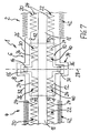
Fig. 1 , - Fig. 7
- eine Ausschnittvergrößerung aus
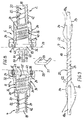
Fig. 2 im Bereich VII der Verbindungsanordnung, - Fig. 8
- ein konkretes Ausführungsbeispiel der Verbindungsanordnung im entkuppelten Zustand ähnlich
Fig. 1 , - Fig. 9
- eine gekürzte Seitenansicht einer beheizbaren Fluidleitung in einem Zustand während der Fertigung zur Erläuterung eines vorteilhaften Fertigungsablaufes,
- Fig. 10
- eine Verbindungsanordnung in einer Prinzip-Darstellung nach Art eines Blockschaltbildes in einer vorteilhaften Ausführung und Verschaltung von elektrischen Heizelementen und
- Fig. 11
- eine schematische Prinzip-Darstellung zu einer bevorzugten Verwendung der erfindungsgemäßen Verbindungsanordnung.
- Fig. 1
- a highly schematic longitudinal sectional view of two prefabricated, heatable fluid lines with a connection arrangement according to the invention in a decoupled state before or after the connection,
- Fig. 2
- the same arrangement as in
Fig. 1 but in the coupled state of the connection arrangement according to the invention, - Fig. 3-6
- Separate representations of individual components of the overall arrangement according to
Fig. 1 . - Fig. 7
- a cutout enlargement
Fig. 2 in area VII of the connection arrangement, - Fig. 8
- a concrete embodiment of the connection arrangement in the uncoupled state similar
Fig. 1 . - Fig. 9
- a shortened side view of a heatable fluid line in a state during production to explain an advantageous manufacturing process,
- Fig. 10
- a connection arrangement in a schematic representation in the manner of a block diagram in an advantageous embodiment and interconnection of electrical heating elements and
- Fig. 11
- a schematic diagram of a preferred use of the connection arrangement according to the invention.
Zu der anschließenden Beschreibung wird ausdrücklich betont, dass die Erfindung nicht auf die Ausführungsbeispiele und dabei nicht auf alle oder mehrere Merkmale von beschriebenen Merkmalskombinationen beschränkt ist, vielmehr kann jedes einzelne Teilmerkmal des/jedes Ausführungsbeispiels auch losgelöst von allen anderen im Zusammenhang damit beschriebenen Teilmerkmalen für sich und auch in Kombination mit beliebigen Merkmalen eines anderen Ausführungsbeispiels eine erfinderische Bedeutung haben.For the following description, it is expressly emphasized that the invention is not limited to the exemplary embodiments and not all or several features of described combinations of features, but each individual feature of the / each embodiment can also be separated from all other partial features described in connection therewith and also have an inventive meaning in combination with any features of another embodiment.
Eine erfindungsgemäße Verbindungsanordnung 1 dient zum schnellen und lösbaren Durchgangsverbinden von zwei elektrisch beheizbaren Fluidleitungen 2 und 4 und besteht dazu aus zwei Kupplungsteilen 6 und 8. Die Kupplungsteile 6, 8 weisen einerseits jeweils eine von zwei korrespondierenden, miteinander fluidisch kuppelbaren und mit jeweils einer der zwei zu verbindenden Fluidleitungen 2, 4 verbundenen Fluidkupplungsteilen 10, 12 sowie andererseits jeweils eines von zwei korrespondierenden, miteinander kuppelbaren Elektro-Steckverbinderteilen 14, 16 derart auf, dass durch Zusammenfügen der beiden Kupplungsteile 6, 8 die Fluidkupplungsteile 10, 12 einerseits und die Elektro-Steckverbinderteile 14, 16 andererseits gemeinsam, also praktisch gleichzeitig verbindbar sind. Ebenso können durch Trennen der beiden Kupplungsteile 6, 8 die Fluidkupplungsteile 10, 12 einerseits und die Elektro-Steckverbinderteile 14, 16 andererseits getrennt werden. Die Verbindungsanordnung 1 erlaubt somit ein schnelles Fügen und Trennen der Fluidverbindung und der, d. h. mindestens einer, elektrischen Verbindung in nur einem gemeinsamen Füge- bzw. Trennvorgang.A
Jede beheizbare Fluidleitung 2, 4 besteht aus einer als Schlauch oder Rohr beispielsweise aus Kunststoff ausgebildeten Medienleitung 18, die zur Beheizung des durch die Leitung 18 geführten Mediums mit mindestens einem elektrischen Heizelement 20 ausgestattet ist. In den dargestellten, bevorzugten Ausführungsbeispielen weist jede Medienleitung 18 zwei Heizelemente 20, 22 auf. Bevorzugt ist das/jedes Heizelement 20, 22 durch einen schraubenlinienförmig um die Medienleitung 18 über deren Länge hinweg gewickelten Heizleiter 24 gebildet, der aus einem geeigneten elektrischen Widerstands-Drahtmaterial besteht, so dass durch einen Stromfluss Wärme erzeugt wird. Bevorzugt ist das/jedes Heizelement 20, 22 jeder Fluidleitung 2, 4 bezüglich des Widerstands-Drahtmaterials und in Anpassung an eine Versorgungsspannung, insbesondere eine Fahrzeug-Bordspannung von 12 oder 24 Volt, so ausgelegt, dass die Leitung mit einer Heizleistung von 15 Watt ± 5 Watt pro Meter Leitungslänge beaufschlagt wird. Dies wird durch Auswahl eines bestimmten Heizdraht-Materials, wie insbesondere CuNi-Heizdraht, und des Draht-Durchmessers sowie der Drahtlänge in Kombination mit der Windungssteigung erreicht. Je nach Drahtmaterial wird eine Gesamt-Drahtlänge von 2000 bis 3000 mm pro Meter Leitungslänge benötigt. Dazu kann eine schraubenlinienförmige Wicklung vorgesehen sein oder mindestens zwei Wicklungen, die bevorzugt in Reihe geschaltet sind. In den
Erfindungsgemäß weisen auch die Fluidkupplungsteile 10, 12 zur Fluidbeheizung jeweils mindestens ein elektrisches Heizelement 26 auf, wobei diese mindestens zwei Heizelemente 26 der beiden Fluidkupplungsteile 10, 12 über die Elektro-Steckverbinderteile 14, 16 unmittelbar elektrisch verbunden oder verbindbar sind. Weiterhin sind dabei die Fluidkupplungsteile 10, 12 erfindungsgemäß unter Einschluss der Heizelemente 26 und der Elektro-Steckverbinderteile 14, 16 von einer in einer Kupplungsebene 28 in zwei Gehäuseteile 30, 32 geteilten Kapselung 34 umschlossen. Jedem Kupplungsteil 6, 8 bzw. dessen Fluidkupplungsteil 10, 12 ist eines der beiden Gehäuseteile 30, 32 der Kapselung 34 zugeordnet.According to the invention, the
In
In bevorzugter Ausgestaltung weist jedes Kupplungsteil 6, 8 mindestens ein weiteres, zweites Elektro-Steckverbinderteil 36, 38 auf, wobei über diese zweiten Elektro-Steckverbinderteile 36, 38 unmittelbar entweder gemäß
In weiterer vorteilhafter Ausgestaltung sind die mit den Fluidkupplungsteilen 10, 12 verbundenen Fluidleitungen 2, 4 gemeinsam mit den zugehörigen Heizelementen 20, 22 von jeweils einer Leitungsumhüllung 42 umschlossen. Vorteilhafterweise geht hierbei jede Leitungsumhüllung 42 einendig in eines der Gehäuseteile 30, 32 der erfindungsgemäßen Kapselung 34 der Kupplungsteile 6, 8 über. Bevorzugt ist jede Leitungsumhüllung 42 mit ihrem Ende formschlüssig in dem zugehörigen Gehäuseteil 30, 32 aufgenommen. Vorzugsweise kann hierzu jede Leitungsumhüllung 42 aus einem Wellrohr bestehen, wobei die Kapselung 34 im Bereich einer Aufnahmeöffnung formschlüssig in die Umfangskontur des Wellrohrs eingreift. Hierzu wird insbesondere auf
Wie sich weiterhin aus
An dieser Stelle sollen noch einige Ausgestaltungsmerkmale kurz erläutert werden, die in den schematischen Zeichnungen teilweise nicht erkennbar sind.At this point, a few design features will be briefly explained, which are partially not visible in the schematic drawings.
Die Kupplungsteile 6, 8 können beliebige geeignete Haltemittel, beispielsweise lösbare Rastmittel, zur gegenseitigen Fixierung in der verbundenen Kupplungslage gemäß
In
Abweichend von
Die Elektro-Steckverbinderteile 14, 16 und optional 36, 38 sind über Haltemittel an den Fluidkupplungsteilen 10, 12 oder alternativ innerhalb der Kapselung 34 gehaltert. Gemäß
Weiterhin sind die Fluidkupplungsteile 10, 12 und die zugehörigen Gehäuseteile 30, 32 der Kapselung 34 relativ zueinander über nicht gesondert dargestellte Haltemittel fixiert.Furthermore, the
Zudem kann optional die Kapselung 34 zumindest teilweise mit einer wärmeisolierenden Masse gefüllt, z. B. vergossen sein. Zwischen der Kapselung 34 und dem jeweiligen Kupplungsteil 6, 8 kann auch ein wärmeisolierender Luftraum gebildet sein.In addition, optionally, the
Die Gehäuseteile 30, 32 der Kapselung 34 können im Bereich der Trennebene 28 dichtend und dazu stumpf anliegend verbindbar oder überlappend ineinandersteckbar und insbesondere über Haltemittel gegenseitig fixierbar sein.The
Weiterhin kann jedes Gehäuseteil 30, 32 der Kapselung 34 aus zwei insbesondere gleichen Hälften bestehen, also insbesondere aus so genannten "Gleichteilen". Es liegen aber auch ungleiche Teile im Bereich der Erfindung.Furthermore, each
Wie sich beispielhaft aus
In diesem Zusammenhang ist in
Wie in
In
Für bestimmte Anforderungen kann es vorteilhaft sein, dass die über die erfindungsgemäße Verbindungsanordnung 1 verbundenen oder zu verbindenden Fluidleitungen 2 und 4 hinsichtlich ihrer Material- und Gebrauchseigenschaften und/oder ihrer konstruktiven Gestaltung verschiedene Ausführungen von Medienleitungen 18 aufweisen. Die gesamte, von den Fluidleitungen 2, 4 gebildete Leitungsverbindung besteht demnach aus unterschiedlichen Längenabschnitten. Dieser Ausgestaltung liegen folgende Gedanken zu Grunde.For certain requirements, it may be advantageous for the
In den genannten SCR-Systemen werden an die beheizbaren Fluidleitungen hohe, sich aus den Beanspruchungsbedingungen ergebende Anforderungen gestellt. Diese Anforderungen betreffen insbesondere das mögliche Auftreten hoher Temperaturen, die an bestimmten Stellen des Systems bzw. der Leitungen z. B. im Bereich von 140°C bis 180°C, kurzzeitig sogar im Bereich bis zu 200°C, liegen können, des Weiteren das Auftreten hoher absoluter Drücke, die standardmäßig im Bereich von 5 bar bis 10 bar, teilweise auch im Bereich bis zu 15 bar, liegen, das Auftreten von Druckpulsationen, die kompensiert werden müssen, sowie auch das Auftreten von Volumenänderungen, die beispielsweise mit dem Gefrieren bei Frost und dem Wiederauftauen des Fluids verbunden sind. Hier spricht man im Hinblick auf die Beanspruchungsgröße von einer so genannten Eisdruckfestigkeit der Leitung.In the abovementioned SCR systems, high demands are made of the heatable fluid lines which arise from the stress conditions. These requirements relate in particular to the possible occurrence of high temperatures at certain points of the system or the lines z. B. in the range of 140 ° C to 180 ° C, for a short time even in the range up to 200 ° C, may also be the occurrence of high absolute pressures, the standard in the range of 5 bar to 10 bar, partially in the range to 15 bar, the occurrence of pressure pulsations, which must be compensated, as well as the occurrence of volume changes, which are associated with, for example, the freezing and the thawing of the fluid. In terms of the load size, this is referred to as a so-called ice pressure resistance of the line.
In diesem Zusammenhang soll eine beheizbare Fluidverbindung geschaffen werden, die bei wenig aufwändiger Herstellungsweise und Montage- bzw. Konnektierungsfähigkeit der Fluidleitung - verglichen mit bekannten Leitungen - erhöhte Anforderungen hinsichtlich der Beständigkeit gegenüber hohen Temperaturen, der Kompensation von Druckpulsationen und/oder der Eisdruckfestigkeit erfüllt.In this context, a heatable fluid connection is to be created, which meets high requirements in terms of resistance to high temperatures, the compensation of pressure pulsations and / or the Eisdruckfestigkeit - with little complex manufacturing and assembly or Konnektierungsfähigkeit the fluid line - compared with known lines.
Dazu sind nun bevorzugt die Medienleitungen 18 der Fluidleitung 2, 4 hinsichtlich ihrer Materialeigenschaften und/oder ihrer konstruktiven Gestalt unterschiedlich ausgebildet, und zwar einerseits als erster Längenabschnitt aus einem ersten Material, welches ein erstes Polymer enthält, und andererseits als zweiter Längenabschnitt aus einem zweiten Material, welches ein zweites Polymer enthält. Dabei ist das zweite Material des zweiten Längenabschnitts flexibler und/oder es weist eine höhere Beanspruchbarkeit auf als das erste Material des ersten Längenabschnitts. Hierbei ist der Fall eingeschlossen, dass die Längenabschnitte bzw. deren Medienleitungen 18 jeweils vollständig aus den genannten Polymeren bestehen.For this purpose, the
Dieser bevorzugten Ausgestaltung liegt die Erkenntnis zugrunde, dass durch eine - wie vorstehend beschrieben - in "Hybridbauweise" ausgeführte beheizbare Leitung die Problematik der konträren, an die Fluidleitung gestellten Anforderungen einer überraschend einfachen technischen Lösung zugeführt werden kann. Dabei erfolgt eine differenzierte Strukturierung der gesamten Leitung, d. h. die verschiedenen Längenabschnitte der Leitung werden entsprechend den lokal unterschiedlich vorliegenden Anforderungen gestaltet, wobei der eine Längenabschnitt die erforderliche Hochtemperaturfestigkeit und/oder Kompensation von Druckpulsationen sowie von Volumenänderungen durch die Einwirkung von Eisdruck für die gesamte Leitung gewährleistet. Auch kann in den verschiedenen Längenabschnitten die chemische Beständigkeit, insbesondere die hydrolytische Beständigkeit der Fluidleitung unter Temperatureinfluss, in besonderer Weise Berücksichtigung finden, indem sie lokal unterschiedlich ausgebildet wird. Das Material des zweiten Längenabschnitts kann also eine im Hinblick auf Temperatur, chemische Beständigkeit und/oder Druck höhere Beanspruchbarkeit aufweisen als das Material des ersten Längenabschnitts.This preferred embodiment is based on the finding that the problem of the contrarian requirements imposed on the fluid line is surprising, as a result of a heatable line designed as described above in "hybrid construction" simple technical solution can be supplied. In this case, a differentiated structuring of the entire line, ie the different lengths of the line are designed according to the locally different requirements, the one length ensures the required high temperature strength and / or compensation of pressure pulsations and volume changes by the influence of ice pressure for the entire line , Also, in the various lengths, the chemical resistance, in particular the hydrolytic resistance of the fluid conduit under the influence of temperature, can be taken into account in a special manner by being formed locally differently. The material of the second length section can therefore have a higher resistance in terms of temperature, chemical resistance and / or pressure than the material of the first length section.
Es sei in diesem Zusammenhang bemerkt, dass die gesamte Fluidverbindung mit Vorteil auch jeweils zwei oder mehr Längenabschnitte umfassen kann, die aus dem ersten polymerhaltigen Material bestehen, und/oder zwei oder mehr Längenabschnitte, die aus dem zweiten, z. B. gummielastischen und damit dehnfähigen, polymerhaltigen Material bestehen.It should be noted in this connection that the entire fluid connection can advantageously also comprise in each case two or more longitudinal sections, which consist of the first polymer-containing material, and / or two or more longitudinal sections, which consist of the second, z. B. rubber-elastic and thus stretchable, polymer-containing material.
Der zweite Längenabschnitt bzw. mehrere Abschnitte dieser Art kann bzw. können für besondere Beanspruchungen, wie höhere Temperaturen, wie sie vor allem in der Nähe einer Einspritzeinrichtung eines SCR-Katalysatorsystems eines Fahrzeug-Verbrennungsmotors und des Abgasstrangs des Motors auftreten, sowie auch zur Anpassung an eine Fluid-Volumenausdehnung beim Gefrieren und an den daraus resultierenden Gefrierdruck ausgelegt sein. Diese Tieftemperaturbeanspruchung tritt in einem SCR-Katalysatorsystem am Ausgang aus einem Fluid-Tank auf, der bei der genannten Anwendung als Vorratsbehälter für das katalytisch wirkende Fluid dient und insbesondere eine wässrige Harnstofflösung enthält.The second length portion or multiple portions of this type can or for special demands, such as higher temperatures, such as occur in the vicinity of an injector of an SCR catalyst system of a vehicle internal combustion engine and the exhaust system of the engine, as well as for adaptation to be designed a fluid volume expansion during freezing and the resulting freezing pressure. This low-temperature stress occurs in an SCR catalyst system at the outlet from a fluid tank, which serves as a reservoir for the catalytically active fluid in the said application and in particular contains an aqueous urea solution.
Das Material des ersten Längenabschnitts kann insbesondere ein Polymer enthalten, das ein technischer Kunststoff ist, während das Material des zweiten Längenabschnitts insbesondere ein Polymer enthalten kann, das ein Hochleistungskunststoff ist.In particular, the material of the first length section may contain a polymer which is a technical plastic, while the material of the second length section may in particular contain a polymer which is a high-performance plastic.
Wenn dabei vorstehend und im Weiteren die Ausdrücke "technischer Kunststoff" und "Hochleistungskunststoff" verwendet werden, so beziehen sich diese Ausdrücke auf eine in der Fachwelt übliche Einteilung der Kunststoffe hinsichtlich ihrer Dauergebrauchstemperatur. Danach wird zwischen Massen- oder Standardkunststoffen mit einer Dauergebrauchstemperatur bis zu 90°C, technischen Kunststoffen mit einer Dauergebrauchstemperatur bis zu 140°C und Hochleistungskunststoffen mit einer Dauergebrauchstemperatur über 140°C unterschieden.If the terms "engineering plastic" and "high performance plastic" are used herein above and below, these terms refer to a classification of plastics in terms of their continuous service temperature which is customary in the art. Thereafter, a distinction is made between mass or standard plastics with a continuous service temperature up to 90 ° C, engineering plastics with a continuous service temperature up to 140 ° C and high performance plastics with a continuous service temperature above 140 ° C.
Die Dauergebrauchstemperatur kann auf verschiedene Weise ermittelt werden. In der Methode nach UL 746 B wird ein so genannter Temperatur-Index angeführt, d. h., es wird diejenige Temperatur bestimmt, bei der der Polymerwerkstoff nach 60 000 bzw. 100 000 Stunden noch die Hälfte seiner Zugfestigkeit, seiner Schlagzugfestigkeit oder seiner elektrischen Durchschlagfestigkeit aufweist. Eine analoge Methode ist die IEC 216 (International Electrical Committee), die der DIN VDE 0304 entspricht. Nach dieser Methode wird diejenige Temperatur bestimmt, bei der nach 20 000 Stunden die Werte der mechanischen und elektrischen Eigenschaften nur noch die Hälfte betragen.The continuous service temperature can be determined in various ways. In the method according to UL 746 B, a so-called temperature index is cited, i. h., It is determined that temperature at which the polymer material after 60,000 or 100,000 hours nor half of its tensile strength, its impact resistance or its dielectric strength. An analogous method is IEC 216 (International Electrical Committee), which complies with DIN VDE 0304. According to this method, the temperature is determined at which, after 20,000 hours, the values of the mechanical and electrical properties are only half.
Als Massenkunststoffe werden aufgrund dieser Kriterien insbesondere Polyethylen (PE), Polypropylen (PP), Polyvinylchlorid (PVC) und Polystyrol (PS) klassifiziert. Zu den technischen Kunststoffen zählen Polymethacrylsäuremethylester (PMMA), Polyamid (PA), Polyethylenterephtalat (PET), Polycarbonat (PC), Acrylnitril-Butadien-Styrol (ABS) und Polyoxymethylen (POM). Zu den Hochleistungskunststoffen zählen Polytetrafluorethylen (PTFE), Polyvinylidenfluorid (PVDF), Polybutylenterephtalat (PBT), Polysulfone (PSU), Polyaryletherketone (PAEK), Polyphenylensulfide (PPS) und Polyimide (PI) sowie verschiedene Copolymere, die die kleinsten repetierenden Ketten-Struktureinheiten der vorgenannten Verbindungen gemeinsam enthalten. Da diese hochwertigen Polymere sehr aufwändig herzustellen und folglich teuer sind, beschränkt sich ihr Einsatz auf bestimmte Spezialfälle. Aus diesem Grund werden diese Werkstoffe trotz ihres exzellenten Eigenschaftsbildes auch nicht zur Herstellung von bekannten Fluidleitungen eingesetzt.Polyethylene (PE), polypropylene (PP), polyvinyl chloride (PVC) and polystyrene (PS) are classified as bulk plastics on the basis of these criteria. Engineering plastics include polymethacrylic acid methyl ester (PMMA), polyamide (PA), polyethylene terephthalate (PET), polycarbonate (PC), acrylonitrile-butadiene-styrene (ABS), and polyoxymethylene (POM). High performance plastics include polytetrafluoroethylene (PTFE), polyvinylidene fluoride (PVDF), polybutylene terephthalate (PBT), polysulfones (PSU), polyaryletherketones (PAEK), polyphenylene sulfides (PPS) and polyimides (PI) and various copolymers containing the smallest repeat chain structural units of the contain the aforementioned compounds together. Since these high quality polymers are very expensive to produce and therefore expensive, limited their commitment to certain special cases. For this reason, these materials are not used despite their excellent characteristics image for the production of known fluid lines.
Ein erster, einen technischen Kunststoff enthaltender, insbesondere vollständig aus diesem Kunststoff bestehender, Längenabschnitt der Medienleitung ist sehr kostengünstig herstellbar und kann deshalb insbesondere in größerer Länge - bzw. in im Vergleich mit dem zweiten Längenabschnitt größerer Länge - innerhalb eines Kraftfahrzeugs eingesetzt werden.A first, a technical plastic-containing, in particular completely made of this plastic existing, longitudinal section of the media line is very inexpensive to produce and can therefore be used in particular in a greater length - or in comparison with the second length section of greater length - within a motor vehicle.
Als polymerer Werkstoff des ersten Längenabschnitts kann dabei mit Vorteil ein Polyamid (PA), insbesondere PA 6, PA 66, PA 11 oder PA 12, gewählt werden, wodurch eine im Hinblick auf den Gesamt-Werkstoffeinsatz aufwandsarme Fertigung der erfindungsgemäßen Fluidleitung gewährleistet werden kann. Der erste Längenabschnitt kann dabei beispielsweise als Kunststoff-Formrohr ausgebildet sein, wobei im Sinne einer erhöhten Stabilität auch gefüllte technische Kunststoffe, z. B. faserverstärkte Kunststoffe, zum Einsatz kommen können.As a polymeric material of the first length section can thereby advantageously a polyamide (PA), in
Polyamide sind eine überaus große Polymerklasse, deren einzelne Vertreter auf unterschiedliche Weise hergestellt werden. Charakteristisch ist dabei das Vorhandensein von funktionellen Amidgruppen -CO-NH- oder auch -CO-NR- im Makromolekül, wobei R einen organischen Rest beschreibt. Zur Bezeichnung der Polyamide mit Kurzzeichen, die aus den Buchstaben "PA" sowie darauf folgenden Zahlen und Buchstaben bestehen, wird auf die Norm DIN EN ISO 1043-1 verwiesen. Hiernach werden Polyamide, die sich von einer Aminocarbonsäure des Typs H2N-(CH2)x-COOH oder den entsprechenden Lactamen ableiten lassen, mit PA Z gekennzeichnet, wobei Z die Anzahl der Kohlenstoffatome im Monomer bezeichnet (Z = x + 1). So steht z. B. PA 6 für ein Polymer, das aus ε-Caprolactam bzw. ω -Aminocapronsäure [NH-(CH2)5-CO]n. hergestellt wird. PA 11 wird aus 11-Aminoundecansäure und PA 12 aus Laurinlactam oder ω-Aminodecansäure hergestellt.Polyamides are a very large class of polymers whose individual representatives are produced in different ways. Characteristic is the presence of functional amide groups -CO-NH- or -CO-NR- in the macromolecule, wherein R describes an organic radical. Reference is made to the standard DIN EN ISO 1043-1 for the designation of the polyamides with abbreviations consisting of the letters "PA" and the following numbers and letters. Hereinafter, polyamides which can be derived from an aminocarboxylic acid of the type H 2 N- (CH 2 ) x -COOH or the corresponding lactams are denoted by PA Z, where Z denotes the number of carbon atoms in the monomer (Z = x + 1) , So z.
PA 11 und PA 12 sind kältebeständig bis mindestens -50°C und dauerwärmebeständig bis höchstens +80°C. Durch Zusatz von Stabilisatoren sowie Weichmachern kann jedoch die Kälte- bzw. Wärmebeständigkeit auf Werte von -60°C bzw. +110°C, kurzzeitig bis 160°C erhöht werden. PA 12 ist beispielsweise unter dem Namen VESTAMIDⓇ L im Handel. Dieser Werkstoff weist nur eine sehr geringe Wasseraufnahme auf, wobei aus ihm hergestellte Formteile bei wechselnder Umgebungsfeuchte nur geringste Dimensionsänderungen zeigen. Selbst weit unter dem Gefrierpunkt hat PA12 eine außerordentlich hohe Schlagzähigkeit und Kerbschlagzähigkeit. Des Weiteren weist es eine gute bis sehr gute chemische Beständigkeit gegen Fette, Öle, Kraftstoffe, Hydraulikflüssigkeiten, viele Lösemittel sowie Salzlösungen und andere Chemikalien auf.PA 11 and
Polyamide, die sich von Diaminen und Dicarbonsäuren der Typen H2N-(CH2)x-NH2 und HOOC-(CH2)y-COOH ableiten lassen, werden mit PA Z1Z2 gekennzeichnet, wobei Z1 die Anzahl der Kohlenstoffatome im Diamin und Z2 die Anzahl der Kohlenstoffatome in der Dicarbonsäure bezeichnet (Z1 = x, Z2 = y + 2). So steht z. B. PA 66 für das Polymer aus Hexamethylendiamin und Adipinsäure, [NH-(CH2)6-NH-CO-(CH2)4-CO]n.Polyamides derived from diamines and dicarboxylic acids of the types H 2 N- (CH 2 ) x -NH 2 and HOOC- (CH 2 ) y -COOH are characterized by PA Z1Z2, where Z1 is the number of carbon atoms in the diamine and Z2 denotes the number of carbon atoms in the dicarboxylic acid (Z1 = x , Z2 = y + 2). So z. B. PA 66 for the polymer of hexamethylenediamine and adipic acid, [NH- (CH 2 ) 6 -NH-CO- (CH 2 ) 4 -CO] n .
Obwohl der Herstellungsprozess der beiden technisch am häufigsten verwendeten Polyamide PA 6 und PA 66 grundlegend verschieden ist, sind PA 6 und PA 66 chemisch und physikalisch sehr ähnlich und unterscheiden sich lediglich durch eine gespiegelte Anordnung einer -CH2-NH-CO-Gruppe. PA 6 und PA 66 sind kältebeständig bis mindestens -30°C und dauerwärmebeständig bis höchstens 105°C, bzw. PA 66 bis maximal 120 °C.Although the manufacturing process of the two most commonly used polyamides,
Das Polymer des zweiten Längenabschnitts kann mit Vorteil ein Elastomer, beispielsweise hydrierter Acrylnitrilbutadien-Kautschuk (HNBR), Ethylen-Propylen-Dien-Kautschuk (EPDM) für eine Temperaturbeanspruchung bis zu 170°C, ein Ethylen-Propylen-Kautschuk (EPM) für eine Temperaturbeanspruchung über 200°C oder auch ein thermoplastisches Elastomer (TPE) sein.The polymer of the second length may advantageously comprise an elastomer, for example hydrogenated acrylonitrile-butadiene rubber (HNBR), ethylene-propylene-diene rubber (EPDM) for a temperature stress up to 170 ° C, an ethylene-propylene rubber (EPM) for a temperature stress above 200 ° C or a thermoplastic elastomer (TPE).
Aus dieser Werkstoffklasse erscheinen besonders PA 12-Elastomere geeignet. Diese sind Blockcopolymere aus PA 12- und aus Polyether-Segmenten (Polyetherblockamide PEBA). Sie zeigen die wesentlichen Eigenschaften von PA12, wobei sich mit zunehmendem Polyether-Gehalt der Elastomercharakter immer mehr ausprägt. Die Polymere werden elastisch biegsamer und kälteschlagzäher.From this material class especially
Dabei kann der zweite Längenabschnitt als - im Vergleich mit dem ersten Längenabschnitt - flexiblerer, für höhere Beanspruchungen, insbesondere höhere Temperaturen und/oder höheren Innendruck, ausgelegter Schlauch ausgeführt werden, der aus einem gummielastischen, insbesondere mehrschichtigen, z. B. gewebeverstärkten Material besteht. Als Druckträgergewebe für eine solche Verstärkung können bei Temperaturen, die im Bereich von etwa 150°C bis 180°C liegen, mit Vorteil Gewebe aus aromatischen Polyamidfasern (Aramid), beispielsweise bekannt unter dem Markennamen Kevlar®, und für noch höhere Temperaturbereiche Gewebe aus Kohlenstofffasern eingesetzt werden.In this case, the second longitudinal section as - compared to the first length section - more flexible, for higher loads, especially higher temperatures and / or higher internal pressure, designed hose, which consists of a rubber-elastic, in particular multi-layered, z. B. fabric reinforced material. As print carrier webs for such reinforcement, at temperatures ranging from about 150 ° C to 180 ° C, fabric of aromatic polyamide fibers (aramid), for example known under the trade name Kevlar®, and for even higher temperature ranges fabric of carbon fibers may advantageously be used be used.
Als Hochleistungskunststoffe können vor allem Fluorpolymere, wie Polytetrafluorethylen (PTFE), Ethylen-Tetrafluorethylen (ETFE), Perfluorethylenpropylen (FEP), Polyarylenetherketone (PEAK), wie Polyphenylene, z. B. Poly[di-(oxy-1,4-phenylen)carbonyl-1,4-phenylen] (Polyetheretherketon, PEEK), Poly[oxy-1,4-phenylenoxy-di-(1,4-phenylencarbonyl-1,4-phenylen] (Polyetheretherketonketon, PEEKK) oder Poly[-oxy-1,4-phenylencarbonyl-1,4-phenylenoxy-di-(1,4-phenylencarbonyl)-1,4-phenylen] (Polyetherketonetherketonketon, PEKEKK) zur Anwendung kommen, oder auch Polyarylensulfide, wie Polyphenylensulfid (PPS), zur Anwendung kommen.As high-performance plastics, especially fluoropolymers, such as polytetrafluoroethylene (PTFE), ethylene-tetrafluoroethylene (ETFE), perfluoroethylene propylene (FEP), polyarylene ether ketones (PEAK), such as polyphenylenes, z. Poly (di (oxy-1,4-phenylene) carbonyl-1,4-phenylene] (polyetheretherketone, PEEK), poly [oxy-1,4-phenylenoxy-di- (1,4-phenylenecarbonyl-1, 4-phenylene] (polyetherether ketone ketone, PEEKK) or poly [oxy-1,4-phenylenecarbonyl-1,4-phenylenoxy-di- (1,4-phenylenecarbonyl) -1,4-phenylene] (polyetherketone ether ketone ketone, PEKEKK) come or even polyarylene sulfides, such as polyphenylene sulfide (PPS) are used.
Was den Werkstoff PTFE betrifft, so weist dieser höchste thermische Beständigkeiten auf. Ein merklicher Abbau tritt erst bei Temperaturen über 350°C ein. Die obere Dauergebrauchstemperatur liegt bei 250°C. Allerdings unterscheidet sich PTFE auch grundlegend vom Schmelzverhalten anderer Polymere, indem es sich bei Temperaturen im Bereich von 325°C bis 340°C bei Ablauf einer Volumenvergrößerung von etwa 30 Prozent aus einer weißen kristallinen in eine transparente amorphe Substanz verwandelt und selbst bei Temperaturen über 400°C formstabil bleibt. Zur Herstellung von Rohren und Schläuchen müssen daher spezielle Techniken angewendet werden, z. B. die Herstellung von extrusionsfähigen und gegebenenfalls später sinterbaren pastösen Massen, die neben PTFE-Teilchen Füllstoffe und Plastifikatoren, wie unter Compoundbildung andere Polymere, z. B. Polyamide, enthalten können. Weniger aufwändig ist jedoch eine Beschichtung, insbesondere eine Innenbeschichtung der Rohrleitung in ihrem zweiten - gegebenenfalls auch im ersten - Längenabschnitt der Rohrleitung, mit PTFE.As far as the material PTFE is concerned, it has the highest thermal resistance. A significant degradation occurs only at temperatures above 350 ° C. The upper continuous service temperature is 250 ° C. However, PTFE differs also fundamentally from the melting behavior of other polymers, by turning from a white crystalline to a transparent amorphous substance at temperatures in the range of 325 ° C to 340 ° C at expiration of a volume increase of about 30 percent and remains dimensionally stable even at temperatures above 400 ° C. , For the production of pipes and hoses special techniques must therefore be applied, for. As the production of extrusive and optionally later sinterable pasty masses, in addition to PTFE particles fillers and plasticizers, such as under compounding other polymers, eg. As polyamides may contain. However, less expensive is a coating, in particular an inner coating of the pipeline in its second - possibly also in the first - length section of the pipeline, with PTFE.
Besonders bevorzugt als mögliche Polymer-Materialien für den zweiten Längenabschnitt sind auch Polyphthalamide (PPA), insbesondere Hochtemperatur-Polyphthalamide (HT-PPA). Dabei handelt es sich um eine Gruppe von Polyamiden, die aus den aromatischen Monomeren Tere- und Isophthalsäure (HOOC-C6H4-COOH) und Hexamethylendiamin (6 C-Atome) hergestellt werden, und die unter den Polyamiden die höchsten Temperaturbeständigkeiten aufweisen. Die Dauerwärmebeständigkeit liegt im Bereich von etwa 150°C bis maximal 160°C. Die Feuchtigkeitsaufnahme liegt im Bereich von nur etwa 0,1 Prozent bis 0,3 Prozent.Also particularly preferred as possible polymer materials for the second length section are polyphthalamides (PPA), in particular high-temperature polyphthalamides (HT-PPA). This is a group of polyamides prepared from the aromatic monomers terephthalic and isophthalic acid (HOOC-C 6 H 4 -COOH) and hexamethylenediamine (6 C-atoms), which have the highest temperature resistance among polyamides. The long-term heat resistance ranges from about 150 ° C to a maximum of 160 ° C. The moisture absorption is in the range of only about 0.1 percent to 0.3 percent.
Ein Vertreter der oben erwähnten Polyamid-Gruppe, die mit PA Z1 Z2 gekennzeichnet wird, ist beispielsweise auch PA 612, welches beispielsweise unter dem Namen VESTAMID® D im Handel ist. Dieses Polyamid ist das Polykondensationsprodukt aus 1,6-Hexamethylendiamin und 1,12-Dodecandisäure. Wenn auch die Carbonamidgruppen-Konzentration in PA 612 geringfügig höher ist als in Polyamid 12, so ist sie doch deutlich niedriger als bei PA 6 bzw. PA 66. Dadurch haben Teile aus PA 612 fast unverändert die oben genannten vorteilhaften Eigenschaften von PA 12. Jedoch weist PA 612 als zusätzlichen Vorteil im Vergleich mit PA 12 einen fast um 40°C höheren Schmelzpunkt auf und hat so eine bessere Wärmeformbeständigkeit. Die Dauerwärmebeständigkeit liegt im Bereich von etwa 130°C bis 140°C. Auch die Rückstell-Elastizität von PA 612 ist bei hoher Nassfestigkeit höher als bei PA 12. Auch PA 612 kann daher mit Vorteil als Polymer im Material des zweiten Längenabschnitts eingesetzt werden.A representative of the above-mentioned polyamide group which is characterized by PA Z1 Z2 is, for example, also PA 612, which is commercially available, for example, under the name VESTAMID® D. This polyamide is the polycondensation product of 1,6-hexamethylenediamine and 1,12-dodecanedioic acid. Although the carbonamide group concentration in PA 612 is slightly higher than in
In diesem Zusammenhang ist zu erwähnen, dass erfindungsgemäß auch noch Polymere unter dem Begriff "Hochleistungskunststoffe" ("High Performance Polymers") subsumiert werden, die eine Dauerwärmebeständigkeit im Bereich von etwa 130°C bis 140°C aufweisen, wobei - wie bereits aus den vorstehenden Ausführungen hervorgeht - eine hohe Wärmebeständigkeit nicht das einzige Kriterium für eine Eignung eines Materials als Polymer für den zweiten Längenabschnitt der Rohrleitung darstellt. Die erwähnten Hochleistungskunststoffe weisen jedoch in der Mehrzahl nicht nur im Hinblick auf die maximale Temperatur, sondern auch im Hinblick auf die minimale Temperatur, die chemische Beständigkeit und/oder den Druck eine höhere Beanspruchbarkeit auf als technische Kunststoffe.In this context, it should be mentioned that, according to the invention, polymers are also subsumed under the term "high performance polymers" which have a long-term heat resistance in the range from about 130.degree. C. to 140.degree As stated above, high heat resistance is not the only criterion for the suitability of a material as a polymer for the second length of pipe. However, the mentioned high-performance plastics have a higher resistance than engineering plastics, not only in terms of maximum temperature, but also in terms of minimum temperature, chemical resistance and / or pressure.
Bei einer Anwendung der beheizbaren Fluidverbindung in einem SCR-Katalysatorsystem kann es gemäß
In weiterer bevorzugter Ausgestaltung ist vorgesehen, dass die Kupplungsteile 6, 8 der erfindungsgemäßen Verbindungsanordnung 1, und zwar insbesondere deren Fluidkupplungsteile 10, 12 bezüglich des jeweiligen Materials entsprechend der jeweils mit dem Fluidkupplungsteil 10 bzw. 12 verbundenen Fluidleitung 2, 4 ausgebildet sind. Bevorzugt gilt dies auch für die Gehäuseteile 30, 32 der Kapselung 34 und/oder für die Leitungsumhüllungen 42. Dies bedeutet mit anderen Worten, dass in Abhängigkeit von dem ersten oder zweiten Material der jeweiligen Fluidleitung 2 oder 4 auch die weiteren, dieser Fluidleitung 2 oder 4 unmittelbar zugeordneten Komponenten ebenfalls zumindest anteilig aus dem gleichen, ersten oder zweiten Material bestehen.In a further preferred embodiment, it is provided that the
Claims (18)
- A connection arrangement (1) for the rapid and detachable through connection of two electrically heatable fluid lines (2, 4), consisting of two coupling parts (6, 8) which have in each case one of two corresponding fluid coupling parts (10, 12) which can be coupled together and are or can be connected to in each case one of the two fluid lines (2, 4) which are to be connected, and in each case at least one electrical plug-in connector part (14, 16; 36, 38), such that by joining the two coupling parts (6, 8) the fluid coupling parts (10, 12) on one hand and the electrical plug-in connector parts (14, 16) on the other hand are jointly able to be connected,
characterised in that the fluid coupling parts (10, 12) for heating fluid have in each case at least one electrical heating element (26 / 40), the heating elements (26 / 40) of the two fluid coupling parts (10, 12) being able to be connected electrically and directly via the electrical plug-in connector parts (14, 16; 36, 38), and the fluid coupling parts (10, 12) including the heating elements (26 / 40) and the electrical plug-in connector parts (14, 16; 36, 38) are encompassed by an encapsulation (34) which is divided in a coupling plane (28) into two housing parts (30, 32). - A connection arrangement according to Claim 1, characterised in that each coupling part (6, 8) has at least one further, second electrical plug-in connector part (36, 38), two heating elements (22) of the two fluid lines (2, 4) or two additional heating elements (40) of the fluid coupling parts (10, 12) being able to be connected together directly via these second electrical plug-in connector parts (36, 38).
- A connection arrangement according to Claim 1 or 2, characterised in that the/each heating element (20, 22, 26, 40) at least partially encompasses the associated fluid coupling part (10, 12) or the associated fluid line (2, 4), and for this purpose consists in particular of a helically wound-around heating conductor (24).
- A connection arrangement according to one of Claims 1 to 3, characterised in that the fluid lines (2, 4) connected with the fluid coupling parts (10, 12) together with the associated heating elements (20, 22) are in each case encompassed by a line sheath (42), each line sheath (42) merging at one end into one of the housing parts (30, 32) of the encapsulation (34) of the coupling parts (6, 8).
- A connection arrangement according to one of Claims 1 to 4, characterised in that each fluid line (2, 4) is connected at its other end opposing the associated coupling part (6, 8) to a line connector (44, 46) which has at least one electrical heating element (48) for heating the fluid.
- A connection arrangement according to one of Claims 1 to 5, characterised in that the/each heating conductor (24) extends continuously without interruption and additional connecting means in the region of transition from the fluid line (2/4) to the respective fluid coupling part (10/12) and/or to the respective line connector (44/46).
- A connection arrangement according to one of Claims 1 to 6, characterised in that the coupling parts (6, 8) have holding means for reciprocal fixing in the connected coupling position.
- A connection arrangement according to one of Claims 1 to 7, characterised in that the electrical plug-in connector parts (14, 16; 36, 38) are held on the fluid coupling parts (10, 12) and/or within the encapsulation (34) via holding means.
- A connection arrangement according to one of Claims 1 to 8, characterised in that the fluid coupling parts (10, 12) and the housing parts (30, 32) of the encapsulation (34) are fixed relative to one another via holding means.
- A connection arrangement according to one of Claims 1 to 9, characterised in that a gap between the encapsulation (34) and the respective coupling part (6, 8) is filled at least partially with an insulating compound and/or forms a heat-insulating air gap.
- A connection arrangement according to one of Claims 1 to 10, characterised in that the housing parts (30, 32) of the encapsulation (34) in the region of the parting plane (28) are able to be connected in sealing manner and being in a butt joint for this purpose, or can be inserted overlapping into one another and can be reciprocally fixed in particular via holding means.
- A connection arrangement according to one of Claims 1 to 11, characterised in that each casing part (30, 32) of the encapsulation (34) consists of two in particular identical halves.
- A connection arrangement according to one of Claims 1 to 12, characterised in that the/each heating element (26, 40) of each fluid coupling part (10, 12) is either connected to the associated heating element (20, 22) of the fluid line (2, 4) via a contact element (52) or merges directly continuously into the heating element (20, 22) of the fluid line (2, 4).
- A connection arrangement according to one of Claims 1 to 13, characterised in that the two fluid lines (2, 4) are of different lengths, the length of the shorter fluid line (2) being at most 50% of the length of the longer fluid line (4).
- A connection arrangement according to one of Claims 1 to 14, characterised in that the two fluid lines (2, 4) are formed differently with respect to their material properties and/or their structural form, namely in particular on one hand of a first material which contains a first polymer, and on the other hand of a second material which contains a second polymer, the second material being more flexible and/or having a higher stressability than the first material.
- A connection arrangement according to one of Claims 1 to 15, characterised in that the heating elements (20, 22, 26, 40, 48) present are electrically connected in series.
- Use of a connection arrangement (1) according to one of the preceding claims for an SCR catalyst system of a combustion engine, wherein via the coupling parts (6, 8) a first, in particular shorter, fluid line (2) which is connected to a fluid tank (54) is connected to a second, in particular longer, fluid line (4).
- A preassembled media line, consisting of an electrically heatable fluid line (2/4) and the connection arrangement (1) according to one of Claims 1 to 16.
Priority Applications (1)
| Application Number | Priority Date | Filing Date | Title |
|---|---|---|---|
| PL11184499T PL2463566T3 (en) | 2010-12-08 | 2011-10-10 | Connection assembly for heatable fluid conduits |
Applications Claiming Priority (1)
| Application Number | Priority Date | Filing Date | Title |
|---|---|---|---|
| DE102010053736.5A DE102010053736B4 (en) | 2010-12-08 | 2010-12-08 | Connecting arrangement for heated fluid lines |
Publications (2)
| Publication Number | Publication Date |
|---|---|
| EP2463566A1 EP2463566A1 (en) | 2012-06-13 |
| EP2463566B1 true EP2463566B1 (en) | 2013-12-11 |
Family
ID=44759564
Family Applications (1)
| Application Number | Title | Priority Date | Filing Date |
|---|---|---|---|
| EP11184499.9A Active EP2463566B1 (en) | 2010-12-08 | 2011-10-10 | Connection assembly for heatable fluid conduits |
Country Status (4)
| Country | Link |
|---|---|
| EP (1) | EP2463566B1 (en) |
| DE (1) | DE102010053736B4 (en) |
| ES (1) | ES2442373T3 (en) |
| PL (1) | PL2463566T3 (en) |
Cited By (2)
| Publication number | Priority date | Publication date | Assignee | Title |
|---|---|---|---|---|
| DE102018126886A1 (en) | 2018-10-19 | 2020-04-23 | Eugen Forschner Gmbh | Connection arrangement |
| EP3180501B1 (en) | 2014-08-12 | 2020-12-23 | NORMA Germany GmbH | Fluid line |
Families Citing this family (9)
| Publication number | Priority date | Publication date | Assignee | Title |
|---|---|---|---|---|
| DE102010053736B4 (en) | 2010-12-08 | 2018-03-29 | Voss Automotive Gmbh | Connecting arrangement for heated fluid lines |
| DE102013220508A1 (en) * | 2013-10-11 | 2015-04-16 | Bayerische Motoren Werke Aktiengesellschaft | Secure line connection |
| DE202014103317U1 (en) * | 2014-07-18 | 2015-10-21 | Rehau Ag + Co. | Media line, in particular for transporting a urea-water solution |
| DE102016117219A1 (en) | 2016-03-10 | 2017-09-14 | Voss Automotive Gmbh | Guided plug connection |
| CN107039862B (en) * | 2017-04-28 | 2018-11-27 | 西南石油大学 | A kind of electrohydraulic mixed power composite cable input and output connector |
| WO2020079247A1 (en) | 2018-10-19 | 2020-04-23 | Eugen Forschner Gmbh | Connection assembly |
| DE102019111131A1 (en) * | 2019-04-30 | 2020-11-05 | Norma Germany Gmbh | Device for connecting fluid lines and other lines |
| CN110719656A (en) * | 2019-11-01 | 2020-01-21 | 安徽华电线缆股份有限公司 | Self-temperature-control heating cable |
| DE102022208426A1 (en) | 2022-08-12 | 2024-02-15 | Continental Automotive Technologies GmbH | Electro-hydraulic connector for a fluid line |
Family Cites Families (9)
| Publication number | Priority date | Publication date | Assignee | Title |
|---|---|---|---|---|
| DE1675400U (en) | 1952-04-09 | 1954-04-22 | Hoffmeister & Sohn G M B H | ELECTRIC SOCKET FOR TUBE LAMPS WITH PLUG-IN CONTACT BASE. |
| US4547029A (en) * | 1983-10-20 | 1985-10-15 | Automation Industries, Inc. | Self-locking electrical and mechanical connecting means and method of making same |
| DE102005021915A1 (en) * | 2004-06-02 | 2005-12-22 | Stocko Contact Gmbh & Co. Kg | Connecting piece for fluid pipe with electrical conductor has contact element electrically connectable to conductor, with free end of contact element is led out from housing to side |
| DE102005057780A1 (en) | 2005-12-02 | 2007-06-06 | Dbk David + Baader Gmbh | Fluid coupling assembly with electrical connector assembly |
| DE202007010502U1 (en) | 2007-07-26 | 2008-11-27 | Voss Automotive Gmbh | Ready-made media line |
| FR2924786A1 (en) * | 2007-12-11 | 2009-06-12 | Coutier Moulage Gen Ind | Fluid e.g. oil, transporting heating conduit for motor vehicle, has electrical connector provided near coupling fitting for supplying electrical energy, and transferring unit to transfer heating power towards coupling fitting zone |
| DE202007018089U1 (en) * | 2007-12-21 | 2009-05-07 | Voss Automotive Gmbh | Heatable media line |
| DE102010030060A1 (en) | 2010-06-15 | 2011-12-15 | Robert Bosch Gmbh | Connector system, exhaust aftertreatment device |
| DE102010053736B4 (en) | 2010-12-08 | 2018-03-29 | Voss Automotive Gmbh | Connecting arrangement for heated fluid lines |
-
2010
- 2010-12-08 DE DE102010053736.5A patent/DE102010053736B4/en not_active Expired - Fee Related
-
2011
- 2011-10-10 EP EP11184499.9A patent/EP2463566B1/en active Active
- 2011-10-10 ES ES11184499.9T patent/ES2442373T3/en active Active
- 2011-10-10 PL PL11184499T patent/PL2463566T3/en unknown
Cited By (3)
| Publication number | Priority date | Publication date | Assignee | Title |
|---|---|---|---|---|
| EP3180501B1 (en) | 2014-08-12 | 2020-12-23 | NORMA Germany GmbH | Fluid line |
| DE102018126886A1 (en) | 2018-10-19 | 2020-04-23 | Eugen Forschner Gmbh | Connection arrangement |
| CN112888890A (en) * | 2018-10-19 | 2021-06-01 | 欧根弗斯彻纳有限公司 | Connecting device |
Also Published As
| Publication number | Publication date |
|---|---|
| DE102010053736A1 (en) | 2012-06-14 |
| PL2463566T3 (en) | 2014-05-30 |
| DE102010053736B4 (en) | 2018-03-29 |
| EP2463566A1 (en) | 2012-06-13 |
| ES2442373T3 (en) | 2014-02-11 |
Similar Documents
| Publication | Publication Date | Title |
|---|---|---|
| EP2463566B1 (en) | Connection assembly for heatable fluid conduits | |
| EP2816272B1 (en) | Heatable fluid line, use of same and method for producing same | |
| EP2220419B1 (en) | Heatable media line | |
| EP2766651B1 (en) | Assembled media line comprising at least a heatable media line and at least a partially heatable line-connector | |
| EP2167860A2 (en) | Connecting device for media-conducting, electrically heatable pipes | |
| DE102012112563B4 (en) | "Assembled fluid line" | |
| WO2014198915A1 (en) | Line connector and line set for fluid media | |
| DE202011106751U1 (en) | At least partially heatable cable connector for a heatable media line and ready-made media line with such a cable connector | |
| DE102013000588A1 (en) | Prefabricated heatable media line, use thereof and method for producing such | |
| EP2593706A1 (en) | Device for connecting a line element to a component | |
| EP2652382B1 (en) | Heatable connection apparatus for media-conducting, electrically heatable hoses | |
| DE102016113493A1 (en) | Cable connector and method of making a cable connector | |
| DE102014018372A1 (en) | Prefabricated heatable media line and method for its production | |
| EP3234316A1 (en) | Device for providing a liquid additive | |
| EP3055602B1 (en) | Multi-part line having an insulating element for insulating a transition region between connector assemblies | |
| EP3172476B1 (en) | Heatable tube | |
| DE102017128658A1 (en) | Conduit system for a fluid-carrying lines | |
| EP3172477A1 (en) | Heatable tube | |
| DE102019212461A1 (en) | Method for connecting and sealing electrical components | |
| DE102011115890A1 (en) | Partially heated line connector for heatable media line of assembled media line, is partially made of thermally conductive material, where heating system or heating elements are assigned outside body of line connector |
Legal Events
| Date | Code | Title | Description |
|---|---|---|---|
| PUAI | Public reference made under article 153(3) epc to a published international application that has entered the european phase |
Free format text: ORIGINAL CODE: 0009012 |
|
| AK | Designated contracting states |
Kind code of ref document: A1 Designated state(s): AL AT BE BG CH CY CZ DE DK EE ES FI FR GB GR HR HU IE IS IT LI LT LU LV MC MK MT NL NO PL PT RO RS SE SI SK SM TR |
|
| AX | Request for extension of the european patent |
Extension state: BA ME |
|
| 17P | Request for examination filed |
Effective date: 20120706 |
|
| GRAP | Despatch of communication of intention to grant a patent |
Free format text: ORIGINAL CODE: EPIDOSNIGR1 |
|
| INTG | Intention to grant announced |
Effective date: 20130502 |
|
| GRAS | Grant fee paid |
Free format text: ORIGINAL CODE: EPIDOSNIGR3 |
|
| GRAA | (expected) grant |
Free format text: ORIGINAL CODE: 0009210 |
|
| AK | Designated contracting states |
Kind code of ref document: B1 Designated state(s): AL AT BE BG CH CY CZ DE DK EE ES FI FR GB GR HR HU IE IS IT LI LT LU LV MC MK MT NL NO PL PT RO RS SE SI SK SM TR |
|
| REG | Reference to a national code |
Ref country code: GB Ref legal event code: FG4D Free format text: NOT ENGLISH |
|
| REG | Reference to a national code |
Ref country code: CH Ref legal event code: EP |
|
| REG | Reference to a national code |
Ref country code: AT Ref legal event code: REF Ref document number: 644784 Country of ref document: AT Kind code of ref document: T Effective date: 20140115 |
|
| REG | Reference to a national code |
Ref country code: IE Ref legal event code: FG4D Free format text: LANGUAGE OF EP DOCUMENT: GERMAN |
|
| REG | Reference to a national code |
Ref country code: DE Ref legal event code: R096 Ref document number: 502011001784 Country of ref document: DE Effective date: 20140206 |
|
| REG | Reference to a national code |
Ref country code: ES Ref legal event code: FG2A Ref document number: 2442373 Country of ref document: ES Kind code of ref document: T3 Effective date: 20140211 |
|
| REG | Reference to a national code |
Ref country code: SE Ref legal event code: TRGR |
|
| REG | Reference to a national code |
Ref country code: NL Ref legal event code: VDEP Effective date: 20131211 |
|
| PG25 | Lapsed in a contracting state [announced via postgrant information from national office to epo] |
Ref country code: NO Free format text: LAPSE BECAUSE OF FAILURE TO SUBMIT A TRANSLATION OF THE DESCRIPTION OR TO PAY THE FEE WITHIN THE PRESCRIBED TIME-LIMIT Effective date: 20140311 Ref country code: NL Free format text: LAPSE BECAUSE OF FAILURE TO SUBMIT A TRANSLATION OF THE DESCRIPTION OR TO PAY THE FEE WITHIN THE PRESCRIBED TIME-LIMIT Effective date: 20131211 Ref country code: FI Free format text: LAPSE BECAUSE OF FAILURE TO SUBMIT A TRANSLATION OF THE DESCRIPTION OR TO PAY THE FEE WITHIN THE PRESCRIBED TIME-LIMIT Effective date: 20131211 Ref country code: LT Free format text: LAPSE BECAUSE OF FAILURE TO SUBMIT A TRANSLATION OF THE DESCRIPTION OR TO PAY THE FEE WITHIN THE PRESCRIBED TIME-LIMIT Effective date: 20131211 Ref country code: HR Free format text: LAPSE BECAUSE OF FAILURE TO SUBMIT A TRANSLATION OF THE DESCRIPTION OR TO PAY THE FEE WITHIN THE PRESCRIBED TIME-LIMIT Effective date: 20131211 |
|
| REG | Reference to a national code |
Ref country code: LT Ref legal event code: MG4D |
|
| PG25 | Lapsed in a contracting state [announced via postgrant information from national office to epo] |
Ref country code: RS Free format text: LAPSE BECAUSE OF FAILURE TO SUBMIT A TRANSLATION OF THE DESCRIPTION OR TO PAY THE FEE WITHIN THE PRESCRIBED TIME-LIMIT Effective date: 20131211 Ref country code: CY Free format text: LAPSE BECAUSE OF FAILURE TO SUBMIT A TRANSLATION OF THE DESCRIPTION OR TO PAY THE FEE WITHIN THE PRESCRIBED TIME-LIMIT Effective date: 20131211 Ref country code: LV Free format text: LAPSE BECAUSE OF FAILURE TO SUBMIT A TRANSLATION OF THE DESCRIPTION OR TO PAY THE FEE WITHIN THE PRESCRIBED TIME-LIMIT Effective date: 20131211 |
|
| REG | Reference to a national code |
Ref country code: PL Ref legal event code: T3 |
|
| PG25 | Lapsed in a contracting state [announced via postgrant information from national office to epo] |
Ref country code: EE Free format text: LAPSE BECAUSE OF FAILURE TO SUBMIT A TRANSLATION OF THE DESCRIPTION OR TO PAY THE FEE WITHIN THE PRESCRIBED TIME-LIMIT Effective date: 20131211 Ref country code: IS Free format text: LAPSE BECAUSE OF FAILURE TO SUBMIT A TRANSLATION OF THE DESCRIPTION OR TO PAY THE FEE WITHIN THE PRESCRIBED TIME-LIMIT Effective date: 20140411 |
|
| PG25 | Lapsed in a contracting state [announced via postgrant information from national office to epo] |
Ref country code: SK Free format text: LAPSE BECAUSE OF FAILURE TO SUBMIT A TRANSLATION OF THE DESCRIPTION OR TO PAY THE FEE WITHIN THE PRESCRIBED TIME-LIMIT Effective date: 20131211 Ref country code: CZ Free format text: LAPSE BECAUSE OF FAILURE TO SUBMIT A TRANSLATION OF THE DESCRIPTION OR TO PAY THE FEE WITHIN THE PRESCRIBED TIME-LIMIT Effective date: 20131211 Ref country code: RO Free format text: LAPSE BECAUSE OF FAILURE TO SUBMIT A TRANSLATION OF THE DESCRIPTION OR TO PAY THE FEE WITHIN THE PRESCRIBED TIME-LIMIT Effective date: 20131211 Ref country code: PT Free format text: LAPSE BECAUSE OF FAILURE TO SUBMIT A TRANSLATION OF THE DESCRIPTION OR TO PAY THE FEE WITHIN THE PRESCRIBED TIME-LIMIT Effective date: 20140411 |
|
| REG | Reference to a national code |
Ref country code: DE Ref legal event code: R026 Ref document number: 502011001784 Country of ref document: DE |
|
| PLBI | Opposition filed |
Free format text: ORIGINAL CODE: 0009260 |
|
| 26 | Opposition filed |
Opponent name: TI AUTOMOTIVE GMBH Effective date: 20140911 |
|
| PLAX | Notice of opposition and request to file observation + time limit sent |
Free format text: ORIGINAL CODE: EPIDOSNOBS2 |
|
| PG25 | Lapsed in a contracting state [announced via postgrant information from national office to epo] |
Ref country code: DK Free format text: LAPSE BECAUSE OF FAILURE TO SUBMIT A TRANSLATION OF THE DESCRIPTION OR TO PAY THE FEE WITHIN THE PRESCRIBED TIME-LIMIT Effective date: 20131211 |
|
| REG | Reference to a national code |
Ref country code: DE Ref legal event code: R026 Ref document number: 502011001784 Country of ref document: DE Effective date: 20140911 |
|
| PLAF | Information modified related to communication of a notice of opposition and request to file observations + time limit |
Free format text: ORIGINAL CODE: EPIDOSCOBS2 |
|
| PG25 | Lapsed in a contracting state [announced via postgrant information from national office to epo] |
Ref country code: SI Free format text: LAPSE BECAUSE OF FAILURE TO SUBMIT A TRANSLATION OF THE DESCRIPTION OR TO PAY THE FEE WITHIN THE PRESCRIBED TIME-LIMIT Effective date: 20131211 |
|
| PLBB | Reply of patent proprietor to notice(s) of opposition received |
Free format text: ORIGINAL CODE: EPIDOSNOBS3 |
|
| PG25 | Lapsed in a contracting state [announced via postgrant information from national office to epo] |
Ref country code: MC Free format text: LAPSE BECAUSE OF FAILURE TO SUBMIT A TRANSLATION OF THE DESCRIPTION OR TO PAY THE FEE WITHIN THE PRESCRIBED TIME-LIMIT Effective date: 20131211 Ref country code: LU Free format text: LAPSE BECAUSE OF FAILURE TO SUBMIT A TRANSLATION OF THE DESCRIPTION OR TO PAY THE FEE WITHIN THE PRESCRIBED TIME-LIMIT Effective date: 20141010 |
|
| REG | Reference to a national code |
Ref country code: CH Ref legal event code: PL |
|
| PG25 | Lapsed in a contracting state [announced via postgrant information from national office to epo] |
Ref country code: BE Free format text: LAPSE BECAUSE OF NON-PAYMENT OF DUE FEES Effective date: 20141031 |
|
| REG | Reference to a national code |
Ref country code: IE Ref legal event code: MM4A |
|
| PG25 | Lapsed in a contracting state [announced via postgrant information from national office to epo] |
Ref country code: CH Free format text: LAPSE BECAUSE OF NON-PAYMENT OF DUE FEES Effective date: 20141031 Ref country code: LI Free format text: LAPSE BECAUSE OF NON-PAYMENT OF DUE FEES Effective date: 20141031 |
|
| REG | Reference to a national code |
Ref country code: FR Ref legal event code: PLFP Year of fee payment: 5 |
|
| PG25 | Lapsed in a contracting state [announced via postgrant information from national office to epo] |
Ref country code: IE Free format text: LAPSE BECAUSE OF NON-PAYMENT OF DUE FEES Effective date: 20141010 |
|
| PG25 | Lapsed in a contracting state [announced via postgrant information from national office to epo] |
Ref country code: SM Free format text: LAPSE BECAUSE OF FAILURE TO SUBMIT A TRANSLATION OF THE DESCRIPTION OR TO PAY THE FEE WITHIN THE PRESCRIBED TIME-LIMIT Effective date: 20131211 |
|
| PG25 | Lapsed in a contracting state [announced via postgrant information from national office to epo] |
Ref country code: BG Free format text: LAPSE BECAUSE OF FAILURE TO SUBMIT A TRANSLATION OF THE DESCRIPTION OR TO PAY THE FEE WITHIN THE PRESCRIBED TIME-LIMIT Effective date: 20131211 Ref country code: GR Free format text: LAPSE BECAUSE OF FAILURE TO SUBMIT A TRANSLATION OF THE DESCRIPTION OR TO PAY THE FEE WITHIN THE PRESCRIBED TIME-LIMIT Effective date: 20140312 |
|
| PG25 | Lapsed in a contracting state [announced via postgrant information from national office to epo] |
Ref country code: TR Free format text: LAPSE BECAUSE OF FAILURE TO SUBMIT A TRANSLATION OF THE DESCRIPTION OR TO PAY THE FEE WITHIN THE PRESCRIBED TIME-LIMIT Effective date: 20131211 Ref country code: MT Free format text: LAPSE BECAUSE OF FAILURE TO SUBMIT A TRANSLATION OF THE DESCRIPTION OR TO PAY THE FEE WITHIN THE PRESCRIBED TIME-LIMIT Effective date: 20131211 Ref country code: HU Free format text: LAPSE BECAUSE OF FAILURE TO SUBMIT A TRANSLATION OF THE DESCRIPTION OR TO PAY THE FEE WITHIN THE PRESCRIBED TIME-LIMIT; INVALID AB INITIO Effective date: 20111010 |
|
| REG | Reference to a national code |
Ref country code: DE Ref legal event code: R100 Ref document number: 502011001784 Country of ref document: DE |
|
| REG | Reference to a national code |
Ref country code: FR Ref legal event code: PLFP Year of fee payment: 6 |
|
| PLCK | Communication despatched that opposition was rejected |
Free format text: ORIGINAL CODE: EPIDOSNREJ1 |
|
| STAA | Information on the status of an ep patent application or granted ep patent |
Free format text: STATUS: THE PATENT HAS BEEN GRANTED |
|
| PLBN | Opposition rejected |
Free format text: ORIGINAL CODE: 0009273 |
|
| STAA | Information on the status of an ep patent application or granted ep patent |
Free format text: STATUS: OPPOSITION REJECTED |
|
| 27O | Opposition rejected |
Effective date: 20160929 |
|
| REG | Reference to a national code |
Ref country code: FR Ref legal event code: PLFP Year of fee payment: 7 |
|
| REG | Reference to a national code |
Ref country code: AT Ref legal event code: MM01 Ref document number: 644784 Country of ref document: AT Kind code of ref document: T Effective date: 20161010 |
|
| PG25 | Lapsed in a contracting state [announced via postgrant information from national office to epo] |
Ref country code: AT Free format text: LAPSE BECAUSE OF NON-PAYMENT OF DUE FEES Effective date: 20161010 |
|
| PG25 | Lapsed in a contracting state [announced via postgrant information from national office to epo] |
Ref country code: MK Free format text: LAPSE BECAUSE OF FAILURE TO SUBMIT A TRANSLATION OF THE DESCRIPTION OR TO PAY THE FEE WITHIN THE PRESCRIBED TIME-LIMIT Effective date: 20131211 |
|
| PG25 | Lapsed in a contracting state [announced via postgrant information from national office to epo] |
Ref country code: AL Free format text: LAPSE BECAUSE OF FAILURE TO SUBMIT A TRANSLATION OF THE DESCRIPTION OR TO PAY THE FEE WITHIN THE PRESCRIBED TIME-LIMIT Effective date: 20131211 |
|
| REG | Reference to a national code |
Ref country code: FR Ref legal event code: PLFP Year of fee payment: 8 |
|
| P01 | Opt-out of the competence of the unified patent court (upc) registered |
Effective date: 20230526 |
|
| PGFP | Annual fee paid to national office [announced via postgrant information from national office to epo] |
Ref country code: PL Payment date: 20230811 Year of fee payment: 13 |
|
| PGFP | Annual fee paid to national office [announced via postgrant information from national office to epo] |
Ref country code: GB Payment date: 20231010 Year of fee payment: 13 |
|
| PGFP | Annual fee paid to national office [announced via postgrant information from national office to epo] |
Ref country code: ES Payment date: 20231117 Year of fee payment: 13 |
|
| PGFP | Annual fee paid to national office [announced via postgrant information from national office to epo] |
Ref country code: SE Payment date: 20231011 Year of fee payment: 13 Ref country code: IT Payment date: 20231018 Year of fee payment: 13 Ref country code: FR Payment date: 20231011 Year of fee payment: 13 |
|
| PGFP | Annual fee paid to national office [announced via postgrant information from national office to epo] |
Ref country code: DE Payment date: 20231221 Year of fee payment: 13 |