EP2463560A1 - Ball valve - Google Patents
Ball valve Download PDFInfo
- Publication number
- EP2463560A1 EP2463560A1 EP20100306377 EP10306377A EP2463560A1 EP 2463560 A1 EP2463560 A1 EP 2463560A1 EP 20100306377 EP20100306377 EP 20100306377 EP 10306377 A EP10306377 A EP 10306377A EP 2463560 A1 EP2463560 A1 EP 2463560A1
- Authority
- EP
- European Patent Office
- Prior art keywords
- valve
- ball
- seat
- ball body
- integrated
- Prior art date
- Legal status (The legal status is an assumption and is not a legal conclusion. Google has not performed a legal analysis and makes no representation as to the accuracy of the status listed.)
- Granted
Links
Images


Classifications
-
- F—MECHANICAL ENGINEERING; LIGHTING; HEATING; WEAPONS; BLASTING
- F16—ENGINEERING ELEMENTS AND UNITS; GENERAL MEASURES FOR PRODUCING AND MAINTAINING EFFECTIVE FUNCTIONING OF MACHINES OR INSTALLATIONS; THERMAL INSULATION IN GENERAL
- F16K—VALVES; TAPS; COCKS; ACTUATING-FLOATS; DEVICES FOR VENTING OR AERATING
- F16K5/00—Plug valves; Taps or cocks comprising only cut-off apparatus having at least one of the sealing faces shaped as a more or less complete surface of a solid of revolution, the opening and closing movement being predominantly rotary
- F16K5/06—Plug valves; Taps or cocks comprising only cut-off apparatus having at least one of the sealing faces shaped as a more or less complete surface of a solid of revolution, the opening and closing movement being predominantly rotary with plugs having spherical surfaces; Packings therefor
-
- F—MECHANICAL ENGINEERING; LIGHTING; HEATING; WEAPONS; BLASTING
- F16—ENGINEERING ELEMENTS AND UNITS; GENERAL MEASURES FOR PRODUCING AND MAINTAINING EFFECTIVE FUNCTIONING OF MACHINES OR INSTALLATIONS; THERMAL INSULATION IN GENERAL
- F16K—VALVES; TAPS; COCKS; ACTUATING-FLOATS; DEVICES FOR VENTING OR AERATING
- F16K5/00—Plug valves; Taps or cocks comprising only cut-off apparatus having at least one of the sealing faces shaped as a more or less complete surface of a solid of revolution, the opening and closing movement being predominantly rotary
- F16K5/06—Plug valves; Taps or cocks comprising only cut-off apparatus having at least one of the sealing faces shaped as a more or less complete surface of a solid of revolution, the opening and closing movement being predominantly rotary with plugs having spherical surfaces; Packings therefor
- F16K5/0663—Packings
- F16K5/0684—Packings on the plug
-
- F—MECHANICAL ENGINEERING; LIGHTING; HEATING; WEAPONS; BLASTING
- F16—ENGINEERING ELEMENTS AND UNITS; GENERAL MEASURES FOR PRODUCING AND MAINTAINING EFFECTIVE FUNCTIONING OF MACHINES OR INSTALLATIONS; THERMAL INSULATION IN GENERAL
- F16K—VALVES; TAPS; COCKS; ACTUATING-FLOATS; DEVICES FOR VENTING OR AERATING
- F16K27/00—Construction of housing; Use of materials therefor
- F16K27/06—Construction of housing; Use of materials therefor of taps or cocks
- F16K27/067—Construction of housing; Use of materials therefor of taps or cocks with spherical plugs
-
- F—MECHANICAL ENGINEERING; LIGHTING; HEATING; WEAPONS; BLASTING
- F16—ENGINEERING ELEMENTS AND UNITS; GENERAL MEASURES FOR PRODUCING AND MAINTAINING EFFECTIVE FUNCTIONING OF MACHINES OR INSTALLATIONS; THERMAL INSULATION IN GENERAL
- F16K—VALVES; TAPS; COCKS; ACTUATING-FLOATS; DEVICES FOR VENTING OR AERATING
- F16K5/00—Plug valves; Taps or cocks comprising only cut-off apparatus having at least one of the sealing faces shaped as a more or less complete surface of a solid of revolution, the opening and closing movement being predominantly rotary
- F16K5/06—Plug valves; Taps or cocks comprising only cut-off apparatus having at least one of the sealing faces shaped as a more or less complete surface of a solid of revolution, the opening and closing movement being predominantly rotary with plugs having spherical surfaces; Packings therefor
- F16K5/0605—Plug valves; Taps or cocks comprising only cut-off apparatus having at least one of the sealing faces shaped as a more or less complete surface of a solid of revolution, the opening and closing movement being predominantly rotary with plugs having spherical surfaces; Packings therefor with particular plug arrangements, e.g. particular shape or built-in means
-
- F—MECHANICAL ENGINEERING; LIGHTING; HEATING; WEAPONS; BLASTING
- F16—ENGINEERING ELEMENTS AND UNITS; GENERAL MEASURES FOR PRODUCING AND MAINTAINING EFFECTIVE FUNCTIONING OF MACHINES OR INSTALLATIONS; THERMAL INSULATION IN GENERAL
- F16K—VALVES; TAPS; COCKS; ACTUATING-FLOATS; DEVICES FOR VENTING OR AERATING
- F16K5/00—Plug valves; Taps or cocks comprising only cut-off apparatus having at least one of the sealing faces shaped as a more or less complete surface of a solid of revolution, the opening and closing movement being predominantly rotary
- F16K5/06—Plug valves; Taps or cocks comprising only cut-off apparatus having at least one of the sealing faces shaped as a more or less complete surface of a solid of revolution, the opening and closing movement being predominantly rotary with plugs having spherical surfaces; Packings therefor
- F16K5/0663—Packings
- F16K5/0689—Packings between housing and plug
-
- F—MECHANICAL ENGINEERING; LIGHTING; HEATING; WEAPONS; BLASTING
- F16—ENGINEERING ELEMENTS AND UNITS; GENERAL MEASURES FOR PRODUCING AND MAINTAINING EFFECTIVE FUNCTIONING OF MACHINES OR INSTALLATIONS; THERMAL INSULATION IN GENERAL
- F16K—VALVES; TAPS; COCKS; ACTUATING-FLOATS; DEVICES FOR VENTING OR AERATING
- F16K5/00—Plug valves; Taps or cocks comprising only cut-off apparatus having at least one of the sealing faces shaped as a more or less complete surface of a solid of revolution, the opening and closing movement being predominantly rotary
- F16K5/08—Details
- F16K5/14—Special arrangements for separating the sealing faces or for pressing them together
- F16K5/20—Special arrangements for separating the sealing faces or for pressing them together for plugs with spherical surfaces
-
- F—MECHANICAL ENGINEERING; LIGHTING; HEATING; WEAPONS; BLASTING
- F16—ENGINEERING ELEMENTS AND UNITS; GENERAL MEASURES FOR PRODUCING AND MAINTAINING EFFECTIVE FUNCTIONING OF MACHINES OR INSTALLATIONS; THERMAL INSULATION IN GENERAL
- F16K—VALVES; TAPS; COCKS; ACTUATING-FLOATS; DEVICES FOR VENTING OR AERATING
- F16K5/00—Plug valves; Taps or cocks comprising only cut-off apparatus having at least one of the sealing faces shaped as a more or less complete surface of a solid of revolution, the opening and closing movement being predominantly rotary
- F16K5/08—Details
- F16K5/14—Special arrangements for separating the sealing faces or for pressing them together
- F16K5/20—Special arrangements for separating the sealing faces or for pressing them together for plugs with spherical surfaces
- F16K5/201—Special arrangements for separating the sealing faces or for pressing them together for plugs with spherical surfaces with the housing or parts of the housing mechanically pressing the seal against the plug
-
- F—MECHANICAL ENGINEERING; LIGHTING; HEATING; WEAPONS; BLASTING
- F16—ENGINEERING ELEMENTS AND UNITS; GENERAL MEASURES FOR PRODUCING AND MAINTAINING EFFECTIVE FUNCTIONING OF MACHINES OR INSTALLATIONS; THERMAL INSULATION IN GENERAL
- F16K—VALVES; TAPS; COCKS; ACTUATING-FLOATS; DEVICES FOR VENTING OR AERATING
- F16K5/00—Plug valves; Taps or cocks comprising only cut-off apparatus having at least one of the sealing faces shaped as a more or less complete surface of a solid of revolution, the opening and closing movement being predominantly rotary
- F16K5/08—Details
- F16K5/14—Special arrangements for separating the sealing faces or for pressing them together
- F16K5/20—Special arrangements for separating the sealing faces or for pressing them together for plugs with spherical surfaces
- F16K5/204—Special arrangements for separating the sealing faces or for pressing them together for plugs with spherical surfaces with the plugs or parts of the plugs mechanically pressing the seals against the housing
-
- F—MECHANICAL ENGINEERING; LIGHTING; HEATING; WEAPONS; BLASTING
- F16—ENGINEERING ELEMENTS AND UNITS; GENERAL MEASURES FOR PRODUCING AND MAINTAINING EFFECTIVE FUNCTIONING OF MACHINES OR INSTALLATIONS; THERMAL INSULATION IN GENERAL
- F16K—VALVES; TAPS; COCKS; ACTUATING-FLOATS; DEVICES FOR VENTING OR AERATING
- F16K5/00—Plug valves; Taps or cocks comprising only cut-off apparatus having at least one of the sealing faces shaped as a more or less complete surface of a solid of revolution, the opening and closing movement being predominantly rotary
- F16K5/08—Details
- F16K5/14—Special arrangements for separating the sealing faces or for pressing them together
- F16K5/20—Special arrangements for separating the sealing faces or for pressing them together for plugs with spherical surfaces
- F16K5/205—Sealing effected by the flowing medium
-
- Y—GENERAL TAGGING OF NEW TECHNOLOGICAL DEVELOPMENTS; GENERAL TAGGING OF CROSS-SECTIONAL TECHNOLOGIES SPANNING OVER SEVERAL SECTIONS OF THE IPC; TECHNICAL SUBJECTS COVERED BY FORMER USPC CROSS-REFERENCE ART COLLECTIONS [XRACs] AND DIGESTS
- Y10—TECHNICAL SUBJECTS COVERED BY FORMER USPC
- Y10T—TECHNICAL SUBJECTS COVERED BY FORMER US CLASSIFICATION
- Y10T137/00—Fluid handling
- Y10T137/8593—Systems
- Y10T137/87917—Flow path with serial valves and/or closures
- Y10T137/88062—Coaxial oppositely directed seats
Definitions
- Ball valves are capable of controlling a flow through a conduit by using a sphere with a port or hole typically centered in the sphere.
- the valve is opened by rotating the sphere so as to position the port or hole in line with both ends of the valve. A flow may thus move from a first end of the valve, traverse the port or hole, and continue through the second end of the valve.
- the valve is closed by rotating the sphere so as to position the port or hole perpendicular to the ends of the valve.
- the sphere may deform over time under loading conditions, resulting in leakage or improper seals.
- FIG. 1 is a perspective view of a ball valve and valve actuators in accordance with an embodiment of the disclosure
- FIG. 2 is an exploded perspective side view of a trunnion ball valve, including flanged valve ends, a valve body, and a ball body assembly in accordance with an embodiment of the disclosure;
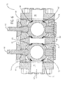
- FIG. 4 is a cross-sectional view of a ball valve in accordance with an embodiment of the disclosure.
- FIG. 5 is a partial cross-sectional view of an annular integrated seat in accordance with an embodiment of the disclosure.
- FIG. 6 is a cross-sectional side view of an embodiment of a double block and bleed valve.
- the disclosed embodiments include a ball valve, such as a trunnion ball valve, having a valve seat integrated in the ball body capable of reducing or eliminating leakage through the bore-to-seat interface.
- the valve seat is disposed in the ball body and includes a geometry and "piston effect" techniques suitable for sealingly maintaining contact with the bore, even in situations where the ball body is not completely spherical. Additional, a substantial portion of the ball body may be left “raw” or unfinished with only the seal and trim areas machined, thus saving time and costs of manufacture.
- the ball valve may be used with piping of different sizes (e.g., approximately between 1/2 in. to 30 in., 15 in. to 45 in., 35 in. to 80 in.
- the ball valve is capable of reducing actuation torque due to a reduced piston effect.
- the integrated seat techniques disclosed herein enable a compact ball valve design suitable for improved installation and maintenance. Indeed, the compact ball valve design eliminates the need for the use of special tools and techniques, such as retracting seat tools and/or sophisticated multiple sealing elements used when servicing traditional ball valves.
- FIG. 1 is a perspective side view of embodiments of a trunnion ball valve 10, a paddle actuator 12, a manual actuator 14, and a hydraulic actuator 16.
- a trunnion or stem 18 of the trunnion ball valve 10 may be connected so any of the actuators 12, 14, or 16 and used to open and close the ball valve by applying a torque.
- the paddle actuator 12 may be connected for subsea applications and used by a remotely operated underwater vehicle (ROV). The ROV may rotate the paddle and thus open or close the ball valve 10.
- the manual actuator 14 may be connected and used for above-ground applications.
- a human operator may turn the wheel 20 of the manual actuator, thus opening or closing the ball valve 10.
- the hydraulic actuator 16 may be used for remote valve activation.
- the ball valve 10 may be remotely opened or closed by remote hydraulic (or electric) actuation. Actuation torque for the ball valve 10 may be reduced by using certain embodiments disclosed herein, such as ball body integrated seats, while enabling the use of higher working pressures.
- the trunnion ball valve 10 includes a valve body 22 having a length L I .
- the valve body 22 may be attached to a set of flanged valve ends 24 and 26, as illustrated.
- the flanged valve ends 24 and 26 may be used to securely connect the valve body 22 to conduit or pipe.
- the flanged valve ends 24 and 26 enable easy installation and removal of the ball valve 10 from a conduit such as a flanged pipe.
- the ball valve 10 may be installed, for example, by using gaskets and a plurality of nuts and bolts suitable for securing the flanged valve ends 24 and 26 to the conduit.
- welds In other applications, such as subsea manifold applications, it may be desirable to fixedly couple the ball valve 10 to the conduit, by using welds. Welding the ball valve 10 to the conduit may reduce weight, create stronger connections, and define a substantially leak-proof passage. Accordingly, the flanged valve ends 24 and 26 may be replaced with a set of weldable valve ends (not shown). Indeed, the use of the certain embodiments described herein, such as integrated seats disposed in a ball body, allow for the use of welding heat without damage to the valve's component parts.
- the weldable valve ends are capable of withstanding the heat generated during welding and may be capable of meeting ISO 14313 (pipeline valves) and ISO 14723 (subsea pipeline valves) specifications.
- the trunnion valve 10 may be capable of meeting a variety of valve-related ISO, ANSI, API, ASME, and/or NACE specifications, including subsea specifications. Further, it is to be understood that other valve ends may be used, including combinations of flanged valve ends, weldable valve ends, and/or hub valve ends. That is, the valve body 22 may include a flange valve end 24 at one end of the valve body 22 and a hub valve end at the opposite end.
- FIG. 2 depicts an exploded perspective view of the trunnion ball valve 10 of FIG. 1 , illustrating details of the flanged valve ends 24 and 26, the valve body 22, and a ball body assembly 28.
- the ball body assembly 28 is configured to enable a flow 30 in an axial direction.
- the flow 30 may be driven, for example, by a pump, a compressor, a well pressure, or any other device capable of creating a movement of a fluid through a fluid passage 32 defined by the internal walls of the valve body 22.
- the ball body assembly 28 includes a ball body 34 having a passage 36, e.g., an approximately circular opening 36.
- the ball body assembly 28 may be disposed inside of the valve body 22 and rotated relative to the valve body 22 so as to open and close the fluid passage 32. Indeed, the rotation of the ball body assembly 28 results in an equivalent rotation of the circular opening 36, thus allowing the flow 30 to enter inwardly into the valve body 22 through one side 31 of the valve body 22, traverse the opening 36 and continue exiting outwardly through the opposite side 33 of the valve body 22. The flow 30 may enter through either of the two sides 31, 33 of the valve body 22 and exit through the opposite side.
- the trunnion ball valve 10 includes the flanged valve ends 24 and 26, which may be secured concentrically or coaxially with respect to the valve body 22 as shown in FIG. 1 . Accordingly, the flow 30 may enter the flanged valve end 24 (or 26) into the valve body 22, traverse through the opening 36, and exit through the flanged 26 (or 24).
- the flange valve ends 24 and 26 may include contact surfaces or walls suitable for engaging a seat 38, such as a toroidal or annular seat 38.
- the annular seat 38 is integrated into the ball body assembly 28 and includes, in certain embodiments, "piston effect" features that enable a more secure sealing of the body assembly 28, even in situations where the ball body 34 may not be completely spherical.
- the piston effect features may include one or more chambers suitable for using the fluid flow 30 to bias the annular seat 38 against the direction of flow.
- the seat 38 allows for the ball body 34 to undergo certain deformation, while the seat 38 maintains a suitable seal against the flow 30 of fluid.
- the seat 38 enables operation of the valve 10 at higher flow pressures, such as pressures approximately between 5-50,000 PSI, and piping sizes of approximately between 1/2 in. to 30 in., 15 in. to 45 in., 35 in. to 80 in.
- Such high pressure, high flow conditions may result in ball body deformations with a corresponding seal leakage in traditional ball valves that do not incorporate the integrated seat 38.
- This leakage is substantially reduced or eliminated by using the integrated seat 38.
- the embodiments disclosed herein enable a substantial improvement in maintaining a suitable even in circumstances where the ball body 34 experiences higher pressures and/or higher flow rates, because most resulting deformations may occur near the stem 18 area of the ball body assembly 28, which is independent from the integrated seat 38.
- the valve body 22 may allow for improved maintenance and/or manufacturing access by including a top entry opening 37 suitable for inserting the ball body assembly 28 into the valve body 22.
- a top entry opening 37 suitable for inserting the ball body assembly 28 into the valve body 22.
- special tools and/or multiple sealing elements may have been needed to remove and replace the ball body 34, for example, because of spring-loaded seats disposed inside a bore 40 of the valve end 24 and on a bore 42 of the valve end 26.
- Such bore-mounted seats may now be replaced with the integrated seats 38 on the ball body assembly 28.
- the ball body assembly 28 may be removed and/or inserted in a ball open position into the valve body 22 without the need for special tools and/or sealing elements.
- the use of the integrated seats 38 on the ball body assembly 28, as described in more detail below with respect to FIG. 3 enables a more easily maintainable and compact ball valve 10.
- FIG. 3 is an exploded perspective side view of an embodiment of the ball body assembly 28.
- the ball body assembly 28 includes the ball body 34 having grooves 44 (e.g., annular grooves) on a first side 31 of the ball body 34.
- the grooves 44 may be milled or machined to form smooth surfaces.
- the grooves 44 are configured to engage an seal 46, a spring 48, a seat ring or washer 50, and the annular seat 38.
- a second annular seat 38, with corresponding grooves 44, seal 46, spring 48, and seat ring 50, is disposed on a second side 33 of the ball body 34 opposite from the seat 38 on the first side 31.
- the use of the integrated seats 38 facilitates an improved seal in a more compact ball valve 10 suitable for enabling high pressure flows.
- manufacturing time and cost may be reduced by leaving most of the ball body 34 unfinished or "raw," That is, the ball body 34 may be cast, but only certain areas of the ball body, such as the areas near or on the grooves 44, may be further treated through machining, milling, and/or the application of a coating. The remainder of the ball body 34 may not come into sealing contact with other valve 10 components, and thus, all ball body areas may not require further treatment and/or coating. It is to be understood that, in other embodiments, other areas of the ball body 34 may receive further treatment, including milling, machining, and/or coating.
- the seal 46 is disposed first onto the grooves 44.
- the seal 46 may enable an improved seal between the seat 38 and the ball body 34.
- the seal 46 may be an elastomeric seal, a plastic seal, a graphite seal, or manufactured out of any other suitable material.
- the spring 48 may then be disposed onto the grooves 44.
- the spring 48 enables a compressive force between the seat 38 and the ball body 34 that may "push" the seat 38 outwardly away from the ball body 34, as described in more detail below with respect to FIG. 4 .
- the spring 48 may thus aid in an enhanced contact between outwardly-facing walls 52 of the seat 38 and certain walls inside the bores 40 and 42 of the ends 24 and 26.
- the outwardly-facing walls 52 may be coated so as to reduce contact friction and to aid in corrosion resistance.
- the outwardly-facing walls 52 may be coated with carbide-based coatings, such as a tungsten carbide coating (TCC), a boron carbide coating, or any other suitable coating.
- TCC tungsten carbide coating
- the seat ring 50 may be disposed between the seat 38 and the spring 48. The ring 50 may be used to limit seat 38 displacement and to maintain spring 48 compressive force. The seat ring 50 may also be provided in different thicknesses and may be used to fine tune the ball valve 10 for different operational environments.
- Thicker seat rings 50 may allow for an increased distance of the seat 38 outwardly from the ball body 34, thus increasing the contact surface and/or contact force between the seat 38 and certain walls of the valve ends 24 and 26.
- slimmer seat rings 50 may allow for a decreased distance of the seat 38 outwardly from the ball body 34, thus decreasing the contact surface and/or contact force between the seat 38 and certain walls oaf the valve end 24.
- the spring 48 may be provided with different spring forces suitable for increasing or decreasing the outward bias of the seat 38 due to the spring 48. In certain embodiments, the spring 48 force be used only to initiate a pressure build up, and the spring 48 force may be a constant value for a given size of valve 10.
- the ball valve 10 may be fine tuned to provide sealing forces suitable for numerous operational environments, such as low pressure environments, medium pressure environments, and high pressure environments.
- the seat 38 may include "piston effect" features, such as described in more detail below with respect to FIG. 4 .
- the piston effect features may be configured to enable operation of the ball valve 10 with sufficient sealing in a variety of operational environments, Indeed, the "piston effect" could be tailored to operate in high pressure applications.
- FIG. 4 is a cross-sectional view of an embodiment of the trunnion ball valve 10 in a fully closed position, As illustrated, the annular integrated seat 38 on the first side 31 is spring biased against a wall 54, and the annular integrated seat 38 on the second side 33 is spring biased against a wall 56.
- the annular seats 38 enable a metal-to-metal contact with the walls 54 and 56.
- the metal-to-metal seating may be useful in applications, such as high temperature applications and/or corrosive fluid applications, Accordingly, the annular seats 38 and the walls 54 and 56 may be manufactured out of a metal and/or a metal alloy, such as inconel, stainless steel, cro-moly steel, and so forth. Additionally, the seats 38 and/or the walls 54 and 56 may be coated (e.g., TCC coated) to reduce friction and improve resistance to corrosion.
- the seats 38 and 39 may enable a "soft seal,” such as an elastomer-to-metal or elastomer-to-elastomer contact.
- the seats 38 and 39, and/or the walls 54 and 56 may include elastomer inserts or may be manufactured out of elastomer materials such as thermoplastics, synthetic rubber, polymers, or other non metallic sealing materials.
- Such "soft seal" embodiments may aid in preventing electrolysis between the contact points should the valve be left in a closed position for prolonged periods of time.
- the seats 38 and 39 may contact a wall of the valve body 22 instead of the walls 54 and 56 of the valve ends 24 and 26. indeed, walls of the valve body 22 may be used to seal the fluid passage 32.
- the ball body 34 may be substantially the same length L 1 as the ball body assembly 28.
- the valve ends 24 and 26 may not require the use of a bore seat.
- the bore seat typically would require additional space because it is separate from the ball body 34. Instead, the valve ends 24 and 26 may directly contact the integrated seats 38 on the ball body 34.
- Such an embodiment results in a more compact ball valve 10 having improved sealing capabilities.
- the valve 10 may also indude a top entry component 58 disposed in the valve body 22, suitable for in-line maintenance. More specifically, the top entry component 58 may be removed, while the remaining components of the valve 10 remain coupled to a conduit 60 (i.e., in-line with the conduit 60). When the top entry component 58 is removed, the ball body assembly 28 components can be inspected, and a maintenance may be performed. For example, components of the ball valve 10 may be replaced, including the seats 38.
- Embodiments of the trunnion ball valve 10 may also include "piston effect" features in which the flow pressure aids in maintaining a secure sealing contact between the seats 38 and the walls 54 and 56.
- the trunnion ball valve 10 is designed to use the fluid pressure to further aid in sealing the seat 38 on the first side 31 and/or the second side 33.
- a fluid flow 62 may enter the bore 40 and impinge upon the ball body 34.
- the fluid flow 62 may result in a pressure against the ball body 34.
- Such a pressure may move the ball body 34 in a downstream fluid 62 direction, biasing the downstream seat 38 more firmly against the wall 56 of the valve end 26.
- a fluid flow 64 may enter the bore 42 and impinge upon the ball body 34, resulting in a fluid pressure against the ball body 34.
- the pressure may move the ball body 34 in a downstream fluid 64 direction, biasing the downstream seat 38 more firmly against the wall 54 of the valve 24.
- FIG. 5 is a partial cross-sectional view of an embodiment of the integrated seat 38 depicted in FIG. 4 taken within line 5-5.
- the trunnion ball valve 10 is designed to use fluid pressure to further aid in sealing both of the two annular seats 38.
- the fluid flow 62 entering the bore 40 may result in a pressure suitable for biasing the seat 38 more firmly against the wall 56.
- This same fluid flow 62 may also result in a pressure suitable for biasing the seat 38 more firmly against the wall 54 of the valve end 24.
- the fluid flow 62 may enter the bore 40 and flow into a chamber 66 of the ball body 34 and a chamber 68 of the integrated seat 38.
- the fluid pressure resulting from the fluid flow 62 entering the chambers 66 and 68 may move or push the seat 38 outwardly towards the wall 54. Indeed, further increase in fluid pressure may result in a corresponding increase in the force of the contact between the upstream seat 38 and the wall 54.
- the seat 46 may aid in maintaining a secure seal downstream of the fluid flow 62.
- the spring 48 may also aid in moving the seat 38 outwardly from the ball body 34.
- the seat 38 is independent of the ball body 34, the seal or contact between the seat 38 and the wall 54 may be maintained even if the ball body 34 moves downstream of the fluid 62 and/or undergoes deformation. Indeed, the ball body 34 may not need to be approximately spherical shape in order for the ball valve 10 to maintain a secure seal. Accordingly, the double piston effect is capable of using the fluid 62 pressure to aid in sealing the seats 38 on both sides 31 and 33.
- FIG. 6 is a cross-sectional view of an embodiment of a multiple ball assembly valve, such as a double block and bleed valve 70, which includes two ball body assemblies 72 and 74. More specifically, the ball body assembly 72 includes annular integrated seats 76 and 78, while the ball body assembly 74 includes annular integrated seats 80 and 82. Indeed, the integrated seats 76, 78, 80, and 82 allow for the manufacturing of compact valves having two (or more) ball body assemblies 72 and 74. In the depicted embodiment, the use of the two ball body assemblies 72 and 74 provides for dual isolation of a flow. For example, the first ball body assembly 72 may be used to stop a fluid flow 83, while maintenance activities are carried out in the second ball body assembly 74.
- a multiple ball assembly valve such as a double block and bleed valve 70
- each of the ball body assemblies 72 and 74 is capable of isolating a fluid flow from the other assembly
- the depicted double block and bleed valve 70 may be made more compact because the integrated seats 76, 78, 80, and 82 are designed to operate within grooves in the ball assemblies 72 and 74, and thus, the valve 70 may not require seats in the valve ends 84 and 86. Accordingly, that would have been used to add seats on the valve ends 84 and 86 may be eliminated, resulting in a more compact double block and bleed valve 70.
- the ball body assemblies 72 and 74, including integrated seats 76, 78, 80, and 82 may be functionally similar to the single ball assembly 28 having the integrated seats 38 but may have different sizes and or shapes to more suitably operate in a valve body 88.
- a stem 90 may be used to actuate the ball body assembly 72 by rotating the ball body assembly 72 with respect to the valve body 88.
- a stem 92 may be used to actuate the ball body assembly 74 by rotating the ball body assembly 74 with respect to the valve body 88.
- the integrated seat 76 contacts walls of a bore 96 of the valve end 84.
- the integrated seat 78 contacts walls of the valve body 88.
- the integrated seat 80 contacts walls of the valve body 88.
- the integrated seat 82 contacts walls of a bore 98 of the valve end 86.
Landscapes
- Engineering & Computer Science (AREA)
- General Engineering & Computer Science (AREA)
- Mechanical Engineering (AREA)
- Taps Or Cocks (AREA)
Abstract
Description
- This section is intended to introduce the reader to various aspects of art that may be related to various aspects of the present invention, which are described and/or claimed below, This discussion is believed to be helpful in providing the reader with background information to facilitate a better understanding of the various aspects of the present invention. Accordingly, it should be understood that these statements are to be read in this light, and not as admissions of prior art.
- Ball valves are capable of controlling a flow through a conduit by using a sphere with a port or hole typically centered in the sphere. The valve is opened by rotating the sphere so as to position the port or hole in line with both ends of the valve. A flow may thus move from a first end of the valve, traverse the port or hole, and continue through the second end of the valve. Likewise, the valve is closed by rotating the sphere so as to position the port or hole perpendicular to the ends of the valve. Unfortunately, the sphere may deform over time under loading conditions, resulting in leakage or improper seals.
- Various features, aspects, and advantages of the present invention will become better understood when the following detailed description is read with reference to the accompanying figures in which like characters represent like parts throughout the figures, wherein:
-
FIG. 1 is a perspective view of a ball valve and valve actuators in accordance with an embodiment of the disclosure; -
FIG. 2 is an exploded perspective side view of a trunnion ball valve, including flanged valve ends, a valve body, and a ball body assembly in accordance with an embodiment of the disclosure; -
FIG. 4 is a cross-sectional view of a ball valve in accordance with an embodiment of the disclosure; -
FIG. 5 is a partial cross-sectional view of an annular integrated seat in accordance with an embodiment of the disclosure; and -
FIG. 6 is a cross-sectional side view of an embodiment of a double block and bleed valve. -
- 10
- trunnion ball valve
- 12
- paddle actuator
- 14
- manual actuator
- 16
- hydraulic actuator
- 18
- stem
- 20
- wheel
- 22
- valve body
- 24
- flanged valve ends
- 26
- flanged valve ends
- 28
- ball body assembly
- 30
- flow
- 32
- fluid passage
- 34
- ball body
- 36
- passage
- 31
- side
- 33
- side
- 38
- seat
- 37
- top entry opening
- 40
- bore
- 42
- bore
- 44
- grooves
- 46
- seal
- 48
- spring
- 50
- washer
- 52
- outwardly-facing walls
- 54
- wall
- 56
- wall
- 39
- seats
- 58
- top entry component
- 60
- conduit
- 62
- fluid flow
- 64
- fluid flow
- 66
- chamber
- 68
- chamber
- 70
- double block and bleed valve
- 72
- ball body assembly
- 74
- ball body assembly
- 76
- annular integrated seat
- 78
- annular integrated seat
- 80
- annular integrated seat
- 82
- annular integrated seat
- 83
- fluid flow
- 84
- valve end
- 86
- valve end
- 88
- valve body
- 90
- stem
- 92
- stem
- 96
- bore
- 98
- bore
- One or more specific embodiments of the present invention will be described below. These described embodiments are only exemplary of the present invention. Additionally, in an effort to provide a concise description of these exemplary embodiments, all features of an actual implementation may not be described in the specification. It should be appreciated that in the development of any such actual implementation, as in any engineering or design project, numerous implementation-specific decisions must be made to achieve the developers' specific goals, such as compliance with system-related and business-related constraints, which may vary from one implementation to another. Moreover, it should be appreciated that Such a development effort might be complex and time consuming, but would nevertheless be a routine undertaking of design, fabrication, and manufacture for those of ordinary skill having the benefit of this disclosure.
- When introducing elements of various embodiments of the present invention, the articles "a," "an," "the," and "said" are intended to mean that there are one or more of the elements. The terms "comprising," "including," and "having" are intended to be inclusive and mean that there may be additional elements other than the listed elements. Moreover, the use of "top," "bottom," "above," "below," and variations of these terms is made for convenience, but does not require any particular orientation of the components.
- The disclosed embodiments include a ball valve, such as a trunnion ball valve, having a valve seat integrated in the ball body capable of reducing or eliminating leakage through the bore-to-seat interface. The valve seat is disposed in the ball body and includes a geometry and "piston effect" techniques suitable for sealingly maintaining contact with the bore, even in situations where the ball body is not completely spherical. Additional, a substantial portion of the ball body may be left "raw" or unfinished with only the seal and trim areas machined, thus saving time and costs of manufacture. The ball valve may be used with piping of different sizes (e.g., approximately between 1/2 in. to 30 in., 15 in. to 45 in., 35 in. to 80 in. diameters) and different flow pressures (e.g., approximately between 5-50,000 PSI). Further, the ball valve is capable of reducing actuation torque due to a reduced piston effect. Additionally, the integrated seat techniques disclosed herein enable a compact ball valve design suitable for improved installation and maintenance. Indeed, the compact ball valve design eliminates the need for the use of special tools and techniques, such as retracting seat tools and/or sophisticated multiple sealing elements used when servicing traditional ball valves.
-
FIG. 1 is a perspective side view of embodiments of atrunnion ball valve 10, apaddle actuator 12, a manual actuator 14, and ahydraulic actuator 16. A trunnion or stem 18 of thetrunnion ball valve 10 may be connected so any of theactuators paddle actuator 12 may be connected for subsea applications and used by a remotely operated underwater vehicle (ROV). The ROV may rotate the paddle and thus open or close theball valve 10. Likewise, the manual actuator 14 may be connected and used for above-ground applications. A human operator may turn thewheel 20 of the manual actuator, thus opening or closing theball valve 10. Further, thehydraulic actuator 16 may be used for remote valve activation. Accordingly, theball valve 10 may be remotely opened or closed by remote hydraulic (or electric) actuation. Actuation torque for theball valve 10 may be reduced by using certain embodiments disclosed herein, such as ball body integrated seats, while enabling the use of higher working pressures. - In the illustrated embodiment, the
trunnion ball valve 10 includes avalve body 22 having a length LI. Thevalve body 22 may be attached to a set of flanged valve ends 24 and 26, as illustrated. In certain applications, such as applications specifying quick removal and replacement of a valve, the flanged valve ends 24 and 26 may be used to securely connect thevalve body 22 to conduit or pipe. The flanged valve ends 24 and 26 enable easy installation and removal of theball valve 10 from a conduit such as a flanged pipe. Theball valve 10 may be installed, for example, by using gaskets and a plurality of nuts and bolts suitable for securing the flanged valve ends 24 and 26 to the conduit. In other applications, such as subsea manifold applications, it may be desirable to fixedly couple theball valve 10 to the conduit, by using welds. Welding theball valve 10 to the conduit may reduce weight, create stronger connections, and define a substantially leak-proof passage. Accordingly, the flanged valve ends 24 and 26 may be replaced with a set of weldable valve ends (not shown). Indeed, the use of the certain embodiments described herein, such as integrated seats disposed in a ball body, allow for the use of welding heat without damage to the valve's component parts. The weldable valve ends are capable of withstanding the heat generated during welding and may be capable of meeting ISO 14313 (pipeline valves) and ISO 14723 (subsea pipeline valves) specifications. Indeed, thetrunnion valve 10 may be capable of meeting a variety of valve-related ISO, ANSI, API, ASME, and/or NACE specifications, including subsea specifications. Further, it is to be understood that other valve ends may be used, including combinations of flanged valve ends, weldable valve ends, and/or hub valve ends. That is, thevalve body 22 may include aflange valve end 24 at one end of thevalve body 22 and a hub valve end at the opposite end. -
FIG. 2 depicts an exploded perspective view of thetrunnion ball valve 10 ofFIG. 1 , illustrating details of the flanged valve ends 24 and 26, thevalve body 22, and aball body assembly 28. Theball body assembly 28 is configured to enable aflow 30 in an axial direction. Theflow 30 may be driven, for example, by a pump, a compressor, a well pressure, or any other device capable of creating a movement of a fluid through afluid passage 32 defined by the internal walls of thevalve body 22. In the depicted embodiment, theball body assembly 28 includes aball body 34 having apassage 36, e.g., an approximatelycircular opening 36. Theball body assembly 28 may be disposed inside of thevalve body 22 and rotated relative to thevalve body 22 so as to open and close thefluid passage 32. Indeed, the rotation of theball body assembly 28 results in an equivalent rotation of thecircular opening 36, thus allowing theflow 30 to enter inwardly into thevalve body 22 through oneside 31 of thevalve body 22, traverse theopening 36 and continue exiting outwardly through theopposite side 33 of thevalve body 22. Theflow 30 may enter through either of the twosides valve body 22 and exit through the opposite side. - In the depicted embodiment, the
trunnion ball valve 10 includes the flanged valve ends 24 and 26, which may be secured concentrically or coaxially with respect to thevalve body 22 as shown inFIG. 1 . Accordingly, theflow 30 may enter the flanged valve end 24 (or 26) into thevalve body 22, traverse through theopening 36, and exit through the flanged 26 (or 24). In certain embodiments, the flange valve ends 24 and 26 may include contact surfaces or walls suitable for engaging aseat 38, such as a toroidal orannular seat 38. Theannular seat 38 is integrated into theball body assembly 28 and includes, in certain embodiments, "piston effect" features that enable a more secure sealing of thebody assembly 28, even in situations where theball body 34 may not be completely spherical. For example, the piston effect features may include one or more chambers suitable for using thefluid flow 30 to bias theannular seat 38 against the direction of flow. Indeed, theseat 38 allows for theball body 34 to undergo certain deformation, while theseat 38 maintains a suitable seal against theflow 30 of fluid. - The
seat 38 enables operation of thevalve 10 at higher flow pressures, such as pressures approximately between 5-50,000 PSI, and piping sizes of approximately between 1/2 in. to 30 in., 15 in. to 45 in., 35 in. to 80 in. Such high pressure, high flow conditions may result in ball body deformations with a corresponding seal leakage in traditional ball valves that do not incorporate theintegrated seat 38. This leakage is substantially reduced or eliminated by using theintegrated seat 38. Indeed, the embodiments disclosed herein enable a substantial improvement in maintaining a suitable even in circumstances where theball body 34 experiences higher pressures and/or higher flow rates, because most resulting deformations may occur near thestem 18 area of theball body assembly 28, which is independent from theintegrated seat 38. - In certain embodiments, the
valve body 22 may allow for improved maintenance and/or manufacturing access by including a top entry opening 37 suitable for inserting theball body assembly 28 into thevalve body 22. Traditionally, special tools and/or multiple sealing elements may have been needed to remove and replace theball body 34, for example, because of spring-loaded seats disposed inside abore 40 of thevalve end 24 and on abore 42 of thevalve end 26. Such bore-mounted seats may now be replaced with theintegrated seats 38 on theball body assembly 28. Accordingly, theball body assembly 28 may be removed and/or inserted in a ball open position into thevalve body 22 without the need for special tools and/or sealing elements. Indeed, the use of theintegrated seats 38 on theball body assembly 28, as described in more detail below with respect toFIG. 3 , enables a more easily maintainable andcompact ball valve 10. -
FIG. 3 is an exploded perspective side view of an embodiment of theball body assembly 28. In the depicted embodiment, theball body assembly 28, includes theball body 34 having grooves 44 (e.g., annular grooves) on afirst side 31 of theball body 34. Thegrooves 44 may be milled or machined to form smooth surfaces. Thegrooves 44 are configured to engage anseal 46, aspring 48, a seat ring orwasher 50, and theannular seat 38. A secondannular seat 38, with correspondinggrooves 44,seal 46,spring 48, andseat ring 50, is disposed on asecond side 33 of theball body 34 opposite from theseat 38 on thefirst side 31. The use of theintegrated seats 38 facilitates an improved seal in a morecompact ball valve 10 suitable for enabling high pressure flows. - In certain embodiments, manufacturing time and cost may be reduced by leaving most of the
ball body 34 unfinished or "raw," That is, theball body 34 may be cast, but only certain areas of the ball body, such as the areas near or on thegrooves 44, may be further treated through machining, milling, and/or the application of a coating. The remainder of theball body 34 may not come into sealing contact withother valve 10 components, and thus, all ball body areas may not require further treatment and/or coating. It is to be understood that, in other embodiments, other areas of theball body 34 may receive further treatment, including milling, machining, and/or coating. - In the depicted embodiment, the
seal 46 is disposed first onto thegrooves 44. Theseal 46 may enable an improved seal between theseat 38 and theball body 34. Accordingly, theseal 46 may be an elastomeric seal, a plastic seal, a graphite seal, or manufactured out of any other suitable material. Thespring 48 may then be disposed onto thegrooves 44. Thespring 48 enables a compressive force between theseat 38 and theball body 34 that may "push" theseat 38 outwardly away from theball body 34, as described in more detail below with respect toFIG. 4 . Thespring 48 may thus aid in an enhanced contact between outwardly-facingwalls 52 of theseat 38 and certain walls inside thebores ends walls 52 may be coated so as to reduce contact friction and to aid in corrosion resistance. For example, the outwardly-facingwalls 52 may be coated with carbide-based coatings, such as a tungsten carbide coating (TCC), a boron carbide coating, or any other suitable coating. Theseat ring 50 may be disposed between theseat 38 and thespring 48. Thering 50 may be used to limitseat 38 displacement and to maintainspring 48 compressive force. Theseat ring 50 may also be provided in different thicknesses and may be used to fine tune theball valve 10 for different operational environments. - Thicker seat rings 50 may allow for an increased distance of the
seat 38 outwardly from theball body 34, thus increasing the contact surface and/or contact force between theseat 38 and certain walls of the valve ends 24 and 26. Similarly, slimmer seat rings 50 may allow for a decreased distance of theseat 38 outwardly from theball body 34, thus decreasing the contact surface and/or contact force between theseat 38 and certain walls oaf thevalve end 24. Likewise, thespring 48 may be provided with different spring forces suitable for increasing or decreasing the outward bias of theseat 38 due to thespring 48. In certain embodiments, thespring 48 force be used only to initiate a pressure build up, and thespring 48 force may be a constant value for a given size ofvalve 10. Accordingly, theball valve 10 may be fine tuned to provide sealing forces suitable for numerous operational environments, such as low pressure environments, medium pressure environments, and high pressure environments. In certain embodiments, theseat 38 may include "piston effect" features, such as described in more detail below with respect toFIG. 4 . The piston effect features may be configured to enable operation of theball valve 10 with sufficient sealing in a variety of operational environments, Indeed, the "piston effect" could be tailored to operate in high pressure applications. -
FIG. 4 is a cross-sectional view of an embodiment of thetrunnion ball valve 10 in a fully closed position, As illustrated, the annularintegrated seat 38 on thefirst side 31 is spring biased against awall 54, and the annularintegrated seat 38 on thesecond side 33 is spring biased against awall 56. In certain embodiments, theannular seats 38 enable a metal-to-metal contact with thewalls annular seats 38 and thewalls seats 38 and/or thewalls - In other embodiments, the
seats seats walls seats valve body 22 instead of thewalls valve body 22 may be used to seal thefluid passage 32. - The use of the
annular seats 38 results in a morecompact ball valve 10. For example, theball body 34 may be substantially the same length L1 as theball body assembly 28. Additional, the valve ends 24 and 26 may not require the use of a bore seat. The bore seat typically would require additional space because it is separate from theball body 34. Instead, the valve ends 24 and 26 may directly contact theintegrated seats 38 on theball body 34. Such an embodiment results in a morecompact ball valve 10 having improved sealing capabilities. Thevalve 10 may also indude atop entry component 58 disposed in thevalve body 22, suitable for in-line maintenance. More specifically, thetop entry component 58 may be removed, while the remaining components of thevalve 10 remain coupled to a conduit 60 (i.e., in-line with the conduit 60). When thetop entry component 58 is removed, theball body assembly 28 components can be inspected, and a maintenance may be performed. For example, components of theball valve 10 may be replaced, including theseats 38. - Embodiments of the
trunnion ball valve 10 may also include "piston effect" features in which the flow pressure aids in maintaining a secure sealing contact between theseats 38 and thewalls trunnion ball valve 10 is designed to use the fluid pressure to further aid in sealing theseat 38 on thefirst side 31 and/or thesecond side 33. For example, afluid flow 62 may enter thebore 40 and impinge upon theball body 34. Thefluid flow 62 may result in a pressure against theball body 34. Such a pressure may move theball body 34 in adownstream fluid 62 direction, biasing thedownstream seat 38 more firmly against thewall 56 of thevalve end 26. Indeed, increasing the fluid flow pressure may correspondingly increase the piston effect pressure against theball body 34, thus resulting in a more secure seal of theseat 38. Likewise, afluid flow 64 may enter thebore 42 and impinge upon theball body 34, resulting in a fluid pressure against theball body 34. The pressure may move theball body 34 in adownstream fluid 64 direction, biasing thedownstream seat 38 more firmly against thewall 54 of thevalve 24. -
FIG. 5 is a partial cross-sectional view of an embodiment of theintegrated seat 38 depicted inFIG. 4 taken within line 5-5. In a double piston effect embodiment, thetrunnion ball valve 10 is designed to use fluid pressure to further aid in sealing both of the twoannular seats 38. As mentioned above with respect toFIG. 4 , thefluid flow 62 entering thebore 40 may result in a pressure suitable for biasing theseat 38 more firmly against thewall 56. Thissame fluid flow 62 may also result in a pressure suitable for biasing theseat 38 more firmly against thewall 54 of thevalve end 24. Accordingly, thefluid flow 62 may enter thebore 40 and flow into achamber 66 of theball body 34 and achamber 68 of theintegrated seat 38. The fluid pressure resulting from thefluid flow 62 entering thechambers seat 38 outwardly towards thewall 54. Indeed, further increase in fluid pressure may result in a corresponding increase in the force of the contact between theupstream seat 38 and thewall 54. As theseat 38 moves, theseat 46 may aid in maintaining a secure seal downstream of thefluid flow 62. Additionally, thespring 48 may also aid in moving theseat 38 outwardly from theball body 34. Further, because theseat 38 is independent of theball body 34, the seal or contact between theseat 38 and thewall 54 may be maintained even if theball body 34 moves downstream of the fluid 62 and/or undergoes deformation. Indeed, theball body 34 may not need to be approximately spherical shape in order for theball valve 10 to maintain a secure seal. Accordingly, the double piston effect is capable of using the fluid 62 pressure to aid in sealing theseats 38 on bothsides -
FIG. 6 is a cross-sectional view of an embodiment of a multiple ball assembly valve, such as a double block and bleedvalve 70, which includes twoball body assemblies ball body assembly 72 includes annularintegrated seats ball body assembly 74 includes annularintegrated seats integrated seats ball body assemblies ball body assemblies ball body assembly 72 may be used to stop afluid flow 83, while maintenance activities are carried out in the secondball body assembly 74. Indeed, each of theball body assemblies valve 70 may be made more compact because theintegrated seats ball assemblies valve 70 may not require seats in the valve ends 84 and 86. Accordingly, that would have been used to add seats on the valve ends 84 and 86 may be eliminated, resulting in a more compact double block and bleedvalve 70. Theball body assemblies integrated seats single ball assembly 28 having theintegrated seats 38 but may have different sizes and or shapes to more suitably operate in avalve body 88. - More specifically, a
stem 90 may be used to actuate theball body assembly 72 by rotating theball body assembly 72 with respect to thevalve body 88. Likewise, astem 92 may be used to actuate theball body assembly 74 by rotating theball body assembly 74 with respect to thevalve body 88. In a closed valve position, theintegrated seat 76 contacts walls of abore 96 of thevalve end 84. Additionally, in a closed valve position, theintegrated seat 78 contacts walls of thevalve body 88. Likewise, in a closed valve position, theintegrated seat 80 contacts walls of thevalve body 88. Additionally, in a closed valve position, theintegrated seat 82 contacts walls of abore 98 of thevalve end 86. Indeed, the disclosed embodiments enable a dual flow isolation suitable for performing in-line valve maintenance of either of theball body assemblies - While the invention may be susceptible to various modifications and alternative forms, specific embodiments have been shown by way of example in the drawings and have been described in detail herein. However, it should be understood that the invention is not intended to be limited to the particular forms disclosed. Rather, the invention is to cover all modifications, equivalents, and alternatives falling within the spirit and scope of the invention as defined by the following appended claims.
Claims (15)
- A ball valve (10) comprising:a first ball body assembly (28) having an first integrated seat (38); anda valve body (22) having a fluid passage (32) in fluid communication with the first ball body assembly (28), wherein the first ball body assembly (28) is disposed inside the valve body (22) and is configured to rotate relative to the valve body (22) to open and close the fluid passage (32).
- The ball valve (10) of claim 1, wherein the first integrated seat (38) comprises a first annular seat (38) disposed in a groove (44) of a ball body (34) of the first ball body assembly (28).
- The ball valve (10) of claim 2, wherein the first ball body assembly (28) comprises a second integrated seat (38) disposed on a second groove (44) of the ball body (34) opposite the first groove (44).
- The ball valve (10) of claim 2, wherein the first ball body assembly (28) comprises a spring (48) disposed between the ball body (34) and the first integrated seat (38), and wherein the spring (48) is configured to provide a spring force to bias the first integrated seat (38) outwardly from the ball body (34).
- The ball valve (10) of claim 1, wherein the first ball body assembly (28) is configured to enable a single piston effect.
- The ball valve (10) of claim 1, wherein the first ball body assembly (28) is configured to enable a double piston effect.
- The ball valve (10) of claim 6, wherein the ball body (34) comprises a chamber (66) configured to use fluid pressure to bias the first integrated seat (38) outwardly from a ball body (34).
- The ball valve (10) of claim 6, wherein the first integrated seat (38) comprises a chamber (68) configured to use fluid pressure to bias the integrated seat (38) outwardly from a ball body (34).
- The ball valve (10) of claim 2, comprising a valve end (24) having a bore (40) coupled to the valve body (34) and in fluid communication with the fluid passage (32), wherein the first integrated seat (38) contacts a wall (54) of a bore (40) when the ball valve (10) is in a closed position.
- The ball valve (10) of claim 9, wherein first the integrated seat (38) comprises a first metal, and the wall (54) comprises a second metal.
- The ball valve (10) of claim 1, wherein the valve body (22) comprises a top entry opening (37) enabling the assembly and/or maintenance of the first ball body assembly (28) without using special valve tools.
- The ball valve (70) of claim 1, comprising a second ball body assembly (74), wherein the second ball body assembly (74) is disposed inside the valve body (88) and is configured to rotate relative to the valve body (88) to open and close the fluid passage.
- An integrated seat system comprising:an annular seat (38) disposed on a ball body (34), wherein the annular seat (38) is configured to substantially seal a fluid passage (32) of a valve body (22) when the ball body (34) is in a closed position.
- The integrated seat system of claim 13, wherein the annular seat (38) contacts a wall (54) of a valve end (24) to seal the fluid passage (32) of the valve body (22).
- The integrated seat system of claim 13, wherein the annular seat (38) contacts a wall of the valve body (22) to seal the fluid passage (32) of the valve body (22).
Priority Applications (12)
| Application Number | Priority Date | Filing Date | Title |
|---|---|---|---|
| ES10306377.2T ES2690758T3 (en) | 2010-12-08 | 2010-12-08 | Ball valve |
| EP10306377.2A EP2463560B1 (en) | 2010-12-08 | 2010-12-08 | Ball valve |
| CN201180059360.3A CN103249976B (en) | 2010-12-08 | 2011-11-28 | Ball valve and method of assembling the ball valve |
| CA2820556A CA2820556C (en) | 2010-12-08 | 2011-11-28 | Ball valve |
| PCT/US2011/062253 WO2012078392A1 (en) | 2010-12-08 | 2011-11-28 | Ball valve |
| CN201510259289.3A CN104864116B (en) | 2010-12-08 | 2011-11-28 | Ball valve |
| KR1020137015982A KR102047557B1 (en) | 2010-12-08 | 2011-11-28 | Ball valve |
| CN201510259613.1A CN104989839B (en) | 2010-12-08 | 2011-11-28 | Ball valve |
| US13/315,233 US8727314B2 (en) | 2010-12-08 | 2011-12-08 | Ball valve |
| US13/975,319 US8960642B2 (en) | 2010-12-08 | 2013-08-24 | Ball valve |
| US14/555,625 US9534696B2 (en) | 2010-12-08 | 2014-11-27 | Ball valve |
| US15/396,776 US9964219B2 (en) | 2010-12-08 | 2017-01-02 | Ball valve |
Applications Claiming Priority (1)
| Application Number | Priority Date | Filing Date | Title |
|---|---|---|---|
| EP10306377.2A EP2463560B1 (en) | 2010-12-08 | 2010-12-08 | Ball valve |
Publications (2)
| Publication Number | Publication Date |
|---|---|
| EP2463560A1 true EP2463560A1 (en) | 2012-06-13 |
| EP2463560B1 EP2463560B1 (en) | 2018-07-11 |
Family
ID=44021901
Family Applications (1)
| Application Number | Title | Priority Date | Filing Date |
|---|---|---|---|
| EP10306377.2A Active EP2463560B1 (en) | 2010-12-08 | 2010-12-08 | Ball valve |
Country Status (7)
| Country | Link |
|---|---|
| US (4) | US8727314B2 (en) |
| EP (1) | EP2463560B1 (en) |
| KR (1) | KR102047557B1 (en) |
| CN (3) | CN104864116B (en) |
| CA (1) | CA2820556C (en) |
| ES (1) | ES2690758T3 (en) |
| WO (1) | WO2012078392A1 (en) |
Cited By (5)
| Publication number | Priority date | Publication date | Assignee | Title |
|---|---|---|---|---|
| CN104235416A (en) * | 2013-06-18 | 2014-12-24 | 科普蓝(上海)阀门工业有限公司 | Ball valve |
| CN105134993A (en) * | 2015-10-20 | 2015-12-09 | 洪元生 | Double-orbit ball valve |
| CN109296769A (en) * | 2017-07-25 | 2019-02-01 | 自贡新比隆阀门有限公司 | New floating ball valve |
| CN109538790A (en) * | 2019-01-15 | 2019-03-29 | 白斌将 | Feeding device |
| EP3695145A4 (en) * | 2017-10-10 | 2021-07-14 | Cameron Technologies Limited | PROFILE INTEGRATED SEAT FOR BALL VALVE |
Families Citing this family (21)
| Publication number | Priority date | Publication date | Assignee | Title |
|---|---|---|---|---|
| GB0908259D0 (en) * | 2009-05-14 | 2009-06-24 | Xamol Ltd | Valve assembly |
| GB201015032D0 (en) * | 2010-09-10 | 2010-10-20 | Xamol Ltd | Valve assembly |
| EP2463560B1 (en) * | 2010-12-08 | 2018-07-11 | Cameron International Corporation | Ball valve |
| EP2667066B1 (en) | 2012-05-23 | 2018-01-17 | Cameron International Corporation | Protective facial sealing arrangement |
| EP2667068B1 (en) | 2012-05-23 | 2018-02-14 | Cameron International Corporation | Valve with contoured bore to deflect particles |
| EP2667067A1 (en) | 2012-05-23 | 2013-11-27 | Cameron International Corporation | Valve with adaptive facial sealing ring |
| WO2015099787A1 (en) | 2013-12-27 | 2015-07-02 | Halliburton Energy Services Inc. | Ball valve having dual pistons each individually actuable |
| EP3040588B1 (en) * | 2014-12-31 | 2017-05-03 | Cameron International Corporation | Double piston effect lip seal seating assemblies |
| DE102015106671A1 (en) * | 2015-04-29 | 2016-11-03 | Dr. Ing. H.C. F. Porsche Aktiengesellschaft | pump |
| ITUB20161092A1 (en) * | 2016-02-26 | 2017-08-26 | Bonomi Ind S R L | Ball valve and manufacturing method |
| CN110785593B (en) * | 2017-06-20 | 2022-06-21 | 艾默生过程管理(印度)私人有限公司 | Non-pressure reducing ball valve |
| KR101872422B1 (en) * | 2017-09-18 | 2018-06-28 | 주식회사 엠에스티엔지니어링 | Rotatable valve |
| US10295066B2 (en) * | 2017-10-04 | 2019-05-21 | GM Global Technology Operations LLC | Ball valve geometry and dynamic seal assembly |
| US10591069B2 (en) * | 2017-10-12 | 2020-03-17 | Schaeffler Technologies AG & Co. KG | Compact rotary valve body for coolant control valve |
| US20190226592A1 (en) * | 2018-01-25 | 2019-07-25 | Honeywell International Inc. | Double block and bleed valve with flex bypass for effective and efficient system isolation |
| CN111396615B (en) * | 2020-03-25 | 2022-01-25 | 苏州鸿瑞欣精密技术有限公司 | Canned type integrated form valve body |
| US11460117B1 (en) | 2020-09-21 | 2022-10-04 | Blue Origin Llc | Ball valve with integral seal retraction |
| US11686404B2 (en) * | 2020-12-11 | 2023-06-27 | Dresser, Llc | Reducing noise in ball valves |
| CN114251477B (en) * | 2021-12-23 | 2024-05-28 | 中海油深圳海洋工程技术服务有限公司 | Deepwater integrated ROV single-operated multiple isolation valves |
| CN114992355B (en) * | 2022-06-13 | 2024-10-01 | 凯瑞特阀业集团有限公司 | High-temperature and high-pressure resistant ball valve and control mechanism thereof |
| US12510167B2 (en) * | 2024-02-29 | 2025-12-30 | SCV Valve, LLC | Systems and methods for double piston effect ball valves |
Citations (4)
| Publication number | Priority date | Publication date | Assignee | Title |
|---|---|---|---|---|
| DE1122788B (en) * | 1959-04-21 | 1962-01-25 | Otto Meyer | Cock with a movable end part on the plug and a sealing seat ring that is movably mounted in the housing |
| GB945508A (en) * | 1960-01-26 | 1964-01-02 | Otto Meyer | Improvements in or relating to fluid flow control valves |
| FR1375004A (en) * | 1963-03-08 | 1964-10-16 | Ball valve structure | |
| JPS57144358A (en) * | 1981-02-27 | 1982-09-06 | Sumitomo Rubber Ind Ltd | Pivoting valve |
Family Cites Families (23)
| Publication number | Priority date | Publication date | Assignee | Title |
|---|---|---|---|---|
| US3195857A (en) * | 1962-05-02 | 1965-07-20 | Homer J Shafer | Ball valve construction |
| GB1557725A (en) * | 1976-08-02 | 1979-12-12 | Shell Int Research | Ball valves |
| US4257574A (en) * | 1979-04-02 | 1981-03-24 | Allis-Chalmers Corporation | Spherical valve seal |
| GB2084296A (en) * | 1980-09-19 | 1982-04-07 | Adams Gebrueder Gmbh & Co Kg A | Improvements relating to flap valves |
| DE3124486C2 (en) * | 1981-06-23 | 1983-04-07 | Klein, Schanzlin & Becker Ag, 6710 Frankenthal | Ball valve for hot media |
| US4385747A (en) * | 1982-01-07 | 1983-05-31 | Worcester Controls Corporation | Self-relieving seat and ball valve incorporating the same |
| NO170239C (en) * | 1990-03-19 | 1992-09-23 | Ingolf Klyde | BALL VALVE |
| JPH0545348U (en) * | 1991-04-09 | 1993-06-18 | ミツワガス機器株式会社 | Gascoque |
| NO175387C (en) * | 1992-05-29 | 1994-10-05 | Norske Stats Oljeselskap | Ball valve assembly |
| IT1255971B (en) * | 1992-11-27 | 1995-11-17 | Mario Giacomini | BALL VALVE WITH HOLDING MEANS ON THE SHUTTER |
| US5417405A (en) * | 1994-04-11 | 1995-05-23 | Orbit Valve Company | Obturator for ball valve |
| US5577708A (en) * | 1995-07-25 | 1996-11-26 | James Wang | Ball valve |
| CN1142027A (en) * | 1995-07-28 | 1997-02-05 | 尔哈德·潘农史密斯 | Half ball valve |
| US5833214A (en) * | 1996-06-11 | 1998-11-10 | Victaulic Company Of America | Plug valve with adjustable disc |
| US5632294A (en) * | 1996-06-24 | 1997-05-27 | Scully Signal Company | Locking ball valve for a fluid conduit |
| US6974121B2 (en) * | 2002-03-19 | 2005-12-13 | Fisher Controls International, Inc. | Fluid flow control valve with bi-directional shutoff |
| GB0309660D0 (en) * | 2003-04-29 | 2003-06-04 | Alco Hi Tek Ltd | Valve assembly |
| CN2679436Y (en) * | 2004-01-12 | 2005-02-16 | 王新明 | Ball valve with mobile valve base |
| CN2926698Y (en) * | 2006-04-07 | 2007-07-25 | 李洪 | Fixed membrane metal sealed spherical valve |
| CN201028039Y (en) * | 2007-05-14 | 2008-02-27 | 上海凯德姆阀门制造有限公司 | Double-ball sealing ball valve |
| CN201391628Y (en) * | 2009-02-13 | 2010-01-27 | 上海远东高中压阀门有限公司 | Ball valve |
| CN201462057U (en) * | 2009-07-03 | 2010-05-12 | 温州市展诚阀门有限公司 | Three-piece high-pressure low-torque ball valve |
| EP2463560B1 (en) * | 2010-12-08 | 2018-07-11 | Cameron International Corporation | Ball valve |
-
2010
- 2010-12-08 EP EP10306377.2A patent/EP2463560B1/en active Active
- 2010-12-08 ES ES10306377.2T patent/ES2690758T3/en active Active
-
2011
- 2011-11-28 WO PCT/US2011/062253 patent/WO2012078392A1/en not_active Ceased
- 2011-11-28 KR KR1020137015982A patent/KR102047557B1/en active Active
- 2011-11-28 CN CN201510259289.3A patent/CN104864116B/en active Active
- 2011-11-28 CN CN201180059360.3A patent/CN103249976B/en active Active
- 2011-11-28 CA CA2820556A patent/CA2820556C/en active Active
- 2011-11-28 CN CN201510259613.1A patent/CN104989839B/en active Active
- 2011-12-08 US US13/315,233 patent/US8727314B2/en active Active
-
2013
- 2013-08-24 US US13/975,319 patent/US8960642B2/en active Active
-
2014
- 2014-11-27 US US14/555,625 patent/US9534696B2/en active Active
-
2017
- 2017-01-02 US US15/396,776 patent/US9964219B2/en active Active
Patent Citations (4)
| Publication number | Priority date | Publication date | Assignee | Title |
|---|---|---|---|---|
| DE1122788B (en) * | 1959-04-21 | 1962-01-25 | Otto Meyer | Cock with a movable end part on the plug and a sealing seat ring that is movably mounted in the housing |
| GB945508A (en) * | 1960-01-26 | 1964-01-02 | Otto Meyer | Improvements in or relating to fluid flow control valves |
| FR1375004A (en) * | 1963-03-08 | 1964-10-16 | Ball valve structure | |
| JPS57144358A (en) * | 1981-02-27 | 1982-09-06 | Sumitomo Rubber Ind Ltd | Pivoting valve |
Cited By (9)
| Publication number | Priority date | Publication date | Assignee | Title |
|---|---|---|---|---|
| CN104235416A (en) * | 2013-06-18 | 2014-12-24 | 科普蓝(上海)阀门工业有限公司 | Ball valve |
| CN105134993A (en) * | 2015-10-20 | 2015-12-09 | 洪元生 | Double-orbit ball valve |
| CN109296769A (en) * | 2017-07-25 | 2019-02-01 | 自贡新比隆阀门有限公司 | New floating ball valve |
| EP3695145A4 (en) * | 2017-10-10 | 2021-07-14 | Cameron Technologies Limited | PROFILE INTEGRATED SEAT FOR BALL VALVE |
| US11274751B2 (en) | 2017-10-10 | 2022-03-15 | Cameron International Corporation | Contoured integrated seat for ball valve |
| US11649902B2 (en) | 2017-10-10 | 2023-05-16 | Cameron International Corporation | Ball valve with pistoning seating surfaces |
| EP4375548A3 (en) * | 2017-10-10 | 2024-08-28 | Cameron Technologies Limited | Contoured integrated seat for ball valve |
| CN109538790A (en) * | 2019-01-15 | 2019-03-29 | 白斌将 | Feeding device |
| CN109538790B (en) * | 2019-01-15 | 2024-04-16 | 白斌将 | Feeding device |
Also Published As
| Publication number | Publication date |
|---|---|
| CA2820556C (en) | 2019-02-12 |
| CN104864116A (en) | 2015-08-26 |
| CN104864116B (en) | 2019-09-10 |
| US20120145938A1 (en) | 2012-06-14 |
| WO2012078392A1 (en) | 2012-06-14 |
| KR20130124958A (en) | 2013-11-15 |
| US8960642B2 (en) | 2015-02-24 |
| US20150083254A1 (en) | 2015-03-26 |
| CA2820556A1 (en) | 2012-06-14 |
| KR102047557B1 (en) | 2019-11-21 |
| CN104989839A (en) | 2015-10-21 |
| US8727314B2 (en) | 2014-05-20 |
| US20170138487A1 (en) | 2017-05-18 |
| US9964219B2 (en) | 2018-05-08 |
| CN103249976B (en) | 2015-04-15 |
| US9534696B2 (en) | 2017-01-03 |
| ES2690758T3 (en) | 2018-11-22 |
| CN104989839B (en) | 2019-04-02 |
| US20140054483A1 (en) | 2014-02-27 |
| CN103249976A (en) | 2013-08-14 |
| EP2463560B1 (en) | 2018-07-11 |
Similar Documents
| Publication | Publication Date | Title |
|---|---|---|
| US9964219B2 (en) | Ball valve | |
| CN102365485B (en) | Valves with ceramic trim with protected closing surfaces | |
| US5562116A (en) | Angle entry rotary valve | |
| US8813771B2 (en) | Gate valve | |
| US9194501B2 (en) | Pressure balanced spring loaded overtravel sealing apparatus | |
| EP3446007B1 (en) | Rotary control valve having a clamped valve seat | |
| US9879789B2 (en) | Ball valve seal | |
| AU2011245550B2 (en) | Floating ball valve seal with bellows and C-seal | |
| CN107110384B (en) | Ceramic Lined Valve |
Legal Events
| Date | Code | Title | Description |
|---|---|---|---|
| PUAI | Public reference made under article 153(3) epc to a published international application that has entered the european phase |
Free format text: ORIGINAL CODE: 0009012 |
|
| AK | Designated contracting states |
Kind code of ref document: A1 Designated state(s): AL AT BE BG CH CY CZ DE DK EE ES FI FR GB GR HR HU IE IS IT LI LT LU LV MC MK MT NL NO PL PT RO RS SE SI SK SM TR |
|
| AX | Request for extension of the european patent |
Extension state: BA ME |
|
| 17P | Request for examination filed |
Effective date: 20120710 |
|
| 17Q | First examination report despatched |
Effective date: 20130930 |
|
| GRAP | Despatch of communication of intention to grant a patent |
Free format text: ORIGINAL CODE: EPIDOSNIGR1 |
|
| INTG | Intention to grant announced |
Effective date: 20180209 |
|
| GRAS | Grant fee paid |
Free format text: ORIGINAL CODE: EPIDOSNIGR3 |
|
| GRAA | (expected) grant |
Free format text: ORIGINAL CODE: 0009210 |
|
| AK | Designated contracting states |
Kind code of ref document: B1 Designated state(s): AL AT BE BG CH CY CZ DE DK EE ES FI FR GB GR HR HU IE IS IT LI LT LU LV MC MK MT NL NO PL PT RO RS SE SI SK SM TR |
|
| REG | Reference to a national code |
Ref country code: GB Ref legal event code: FG4D |
|
| REG | Reference to a national code |
Ref country code: CH Ref legal event code: EP |
|
| REG | Reference to a national code |
Ref country code: AT Ref legal event code: REF Ref document number: 1017226 Country of ref document: AT Kind code of ref document: T Effective date: 20180715 |
|
| REG | Reference to a national code |
Ref country code: IE Ref legal event code: FG4D |
|
| REG | Reference to a national code |
Ref country code: DE Ref legal event code: R096 Ref document number: 602010051791 Country of ref document: DE |
|
| REG | Reference to a national code |
Ref country code: FR Ref legal event code: PLFP Year of fee payment: 9 |
|
| REG | Reference to a national code |
Ref country code: NL Ref legal event code: FP |
|
| REG | Reference to a national code |
Ref country code: ES Ref legal event code: FG2A Ref document number: 2690758 Country of ref document: ES Kind code of ref document: T3 Effective date: 20181122 |
|
| REG | Reference to a national code |
Ref country code: LT Ref legal event code: MG4D |
|
| REG | Reference to a national code |
Ref country code: AT Ref legal event code: MK05 Ref document number: 1017226 Country of ref document: AT Kind code of ref document: T Effective date: 20180711 |
|
| PG25 | Lapsed in a contracting state [announced via postgrant information from national office to epo] |
Ref country code: SE Free format text: LAPSE BECAUSE OF FAILURE TO SUBMIT A TRANSLATION OF THE DESCRIPTION OR TO PAY THE FEE WITHIN THE PRESCRIBED TIME-LIMIT Effective date: 20180711 Ref country code: LT Free format text: LAPSE BECAUSE OF FAILURE TO SUBMIT A TRANSLATION OF THE DESCRIPTION OR TO PAY THE FEE WITHIN THE PRESCRIBED TIME-LIMIT Effective date: 20180711 Ref country code: PL Free format text: LAPSE BECAUSE OF FAILURE TO SUBMIT A TRANSLATION OF THE DESCRIPTION OR TO PAY THE FEE WITHIN THE PRESCRIBED TIME-LIMIT Effective date: 20180711 Ref country code: IS Free format text: LAPSE BECAUSE OF FAILURE TO SUBMIT A TRANSLATION OF THE DESCRIPTION OR TO PAY THE FEE WITHIN THE PRESCRIBED TIME-LIMIT Effective date: 20181111 Ref country code: FI Free format text: LAPSE BECAUSE OF FAILURE TO SUBMIT A TRANSLATION OF THE DESCRIPTION OR TO PAY THE FEE WITHIN THE PRESCRIBED TIME-LIMIT Effective date: 20180711 Ref country code: RS Free format text: LAPSE BECAUSE OF FAILURE TO SUBMIT A TRANSLATION OF THE DESCRIPTION OR TO PAY THE FEE WITHIN THE PRESCRIBED TIME-LIMIT Effective date: 20180711 Ref country code: NO Free format text: LAPSE BECAUSE OF FAILURE TO SUBMIT A TRANSLATION OF THE DESCRIPTION OR TO PAY THE FEE WITHIN THE PRESCRIBED TIME-LIMIT Effective date: 20181011 Ref country code: GR Free format text: LAPSE BECAUSE OF FAILURE TO SUBMIT A TRANSLATION OF THE DESCRIPTION OR TO PAY THE FEE WITHIN THE PRESCRIBED TIME-LIMIT Effective date: 20181012 Ref country code: BG Free format text: LAPSE BECAUSE OF FAILURE TO SUBMIT A TRANSLATION OF THE DESCRIPTION OR TO PAY THE FEE WITHIN THE PRESCRIBED TIME-LIMIT Effective date: 20181011 Ref country code: AT Free format text: LAPSE BECAUSE OF FAILURE TO SUBMIT A TRANSLATION OF THE DESCRIPTION OR TO PAY THE FEE WITHIN THE PRESCRIBED TIME-LIMIT Effective date: 20180711 |
|
| PG25 | Lapsed in a contracting state [announced via postgrant information from national office to epo] |
Ref country code: AL Free format text: LAPSE BECAUSE OF FAILURE TO SUBMIT A TRANSLATION OF THE DESCRIPTION OR TO PAY THE FEE WITHIN THE PRESCRIBED TIME-LIMIT Effective date: 20180711 Ref country code: HR Free format text: LAPSE BECAUSE OF FAILURE TO SUBMIT A TRANSLATION OF THE DESCRIPTION OR TO PAY THE FEE WITHIN THE PRESCRIBED TIME-LIMIT Effective date: 20180711 Ref country code: LV Free format text: LAPSE BECAUSE OF FAILURE TO SUBMIT A TRANSLATION OF THE DESCRIPTION OR TO PAY THE FEE WITHIN THE PRESCRIBED TIME-LIMIT Effective date: 20180711 |
|
| REG | Reference to a national code |
Ref country code: DE Ref legal event code: R082 Ref document number: 602010051791 Country of ref document: DE Representative=s name: PRINZ & PARTNER MBB PATENTANWAELTE RECHTSANWAE, DE Ref country code: DE Ref legal event code: R081 Ref document number: 602010051791 Country of ref document: DE Owner name: CAMERON TECHNOLOGIES LIMITED, NL Free format text: FORMER OWNER: CAMERON INTERNATIONAL CORPORATION, HOUSTON, TEX., US |
|
| REG | Reference to a national code |
Ref country code: DE Ref legal event code: R097 Ref document number: 602010051791 Country of ref document: DE |
|
| PG25 | Lapsed in a contracting state [announced via postgrant information from national office to epo] |
Ref country code: EE Free format text: LAPSE BECAUSE OF FAILURE TO SUBMIT A TRANSLATION OF THE DESCRIPTION OR TO PAY THE FEE WITHIN THE PRESCRIBED TIME-LIMIT Effective date: 20180711 Ref country code: RO Free format text: LAPSE BECAUSE OF FAILURE TO SUBMIT A TRANSLATION OF THE DESCRIPTION OR TO PAY THE FEE WITHIN THE PRESCRIBED TIME-LIMIT Effective date: 20180711 Ref country code: CZ Free format text: LAPSE BECAUSE OF FAILURE TO SUBMIT A TRANSLATION OF THE DESCRIPTION OR TO PAY THE FEE WITHIN THE PRESCRIBED TIME-LIMIT Effective date: 20180711 |
|
| PLBE | No opposition filed within time limit |
Free format text: ORIGINAL CODE: 0009261 |
|
| STAA | Information on the status of an ep patent application or granted ep patent |
Free format text: STATUS: NO OPPOSITION FILED WITHIN TIME LIMIT |
|
| PG25 | Lapsed in a contracting state [announced via postgrant information from national office to epo] |
Ref country code: SM Free format text: LAPSE BECAUSE OF FAILURE TO SUBMIT A TRANSLATION OF THE DESCRIPTION OR TO PAY THE FEE WITHIN THE PRESCRIBED TIME-LIMIT Effective date: 20180711 Ref country code: DK Free format text: LAPSE BECAUSE OF FAILURE TO SUBMIT A TRANSLATION OF THE DESCRIPTION OR TO PAY THE FEE WITHIN THE PRESCRIBED TIME-LIMIT Effective date: 20180711 Ref country code: SK Free format text: LAPSE BECAUSE OF FAILURE TO SUBMIT A TRANSLATION OF THE DESCRIPTION OR TO PAY THE FEE WITHIN THE PRESCRIBED TIME-LIMIT Effective date: 20180711 |
|
| 26N | No opposition filed |
Effective date: 20190412 |
|
| REG | Reference to a national code |
Ref country code: CH Ref legal event code: PL |
|
| PG25 | Lapsed in a contracting state [announced via postgrant information from national office to epo] |
Ref country code: SI Free format text: LAPSE BECAUSE OF FAILURE TO SUBMIT A TRANSLATION OF THE DESCRIPTION OR TO PAY THE FEE WITHIN THE PRESCRIBED TIME-LIMIT Effective date: 20180711 Ref country code: LU Free format text: LAPSE BECAUSE OF NON-PAYMENT OF DUE FEES Effective date: 20181208 Ref country code: MC Free format text: LAPSE BECAUSE OF FAILURE TO SUBMIT A TRANSLATION OF THE DESCRIPTION OR TO PAY THE FEE WITHIN THE PRESCRIBED TIME-LIMIT Effective date: 20180711 |
|
| REG | Reference to a national code |
Ref country code: IE Ref legal event code: MM4A |
|
| PG25 | Lapsed in a contracting state [announced via postgrant information from national office to epo] |
Ref country code: IE Free format text: LAPSE BECAUSE OF NON-PAYMENT OF DUE FEES Effective date: 20181208 |
|
| PG25 | Lapsed in a contracting state [announced via postgrant information from national office to epo] |
Ref country code: LI Free format text: LAPSE BECAUSE OF NON-PAYMENT OF DUE FEES Effective date: 20181231 Ref country code: CH Free format text: LAPSE BECAUSE OF NON-PAYMENT OF DUE FEES Effective date: 20181231 |
|
| PG25 | Lapsed in a contracting state [announced via postgrant information from national office to epo] |
Ref country code: MT Free format text: LAPSE BECAUSE OF NON-PAYMENT OF DUE FEES Effective date: 20181208 |
|
| PG25 | Lapsed in a contracting state [announced via postgrant information from national office to epo] |
Ref country code: TR Free format text: LAPSE BECAUSE OF FAILURE TO SUBMIT A TRANSLATION OF THE DESCRIPTION OR TO PAY THE FEE WITHIN THE PRESCRIBED TIME-LIMIT Effective date: 20180711 |
|
| PG25 | Lapsed in a contracting state [announced via postgrant information from national office to epo] |
Ref country code: PT Free format text: LAPSE BECAUSE OF FAILURE TO SUBMIT A TRANSLATION OF THE DESCRIPTION OR TO PAY THE FEE WITHIN THE PRESCRIBED TIME-LIMIT Effective date: 20180711 |
|
| PG25 | Lapsed in a contracting state [announced via postgrant information from national office to epo] |
Ref country code: MK Free format text: LAPSE BECAUSE OF NON-PAYMENT OF DUE FEES Effective date: 20180711 Ref country code: HU Free format text: LAPSE BECAUSE OF FAILURE TO SUBMIT A TRANSLATION OF THE DESCRIPTION OR TO PAY THE FEE WITHIN THE PRESCRIBED TIME-LIMIT; INVALID AB INITIO Effective date: 20101208 Ref country code: CY Free format text: LAPSE BECAUSE OF FAILURE TO SUBMIT A TRANSLATION OF THE DESCRIPTION OR TO PAY THE FEE WITHIN THE PRESCRIBED TIME-LIMIT Effective date: 20180711 |
|
| PGFP | Annual fee paid to national office [announced via postgrant information from national office to epo] |
Ref country code: BE Payment date: 20201116 Year of fee payment: 11 |
|
| PGFP | Annual fee paid to national office [announced via postgrant information from national office to epo] |
Ref country code: NL Payment date: 20201214 Year of fee payment: 11 |
|
| REG | Reference to a national code |
Ref country code: BE Ref legal event code: PD Owner name: CAMERON TECHNOLOGIES LIMITED; IE Free format text: DETAILS ASSIGNMENT: CHANGE OF OWNER(S), ASSIGNMENT; FORMER OWNER NAME: CAMERON INTERNATIONAL CORPORATION Effective date: 20210317 |
|
| PGFP | Annual fee paid to national office [announced via postgrant information from national office to epo] |
Ref country code: ES Payment date: 20210108 Year of fee payment: 11 |
|
| REG | Reference to a national code |
Ref country code: NL Ref legal event code: PD Owner name: CAMERON TECHNOLOGIES LIMITED; IE Free format text: DETAILS ASSIGNMENT: CHANGE OF OWNER(S), ASSIGNMENT; FORMER OWNER NAME: CAMERON INTERNATIONAL CORPORATION Effective date: 20210416 |
|
| REG | Reference to a national code |
Ref country code: NL Ref legal event code: MM Effective date: 20220101 |
|
| REG | Reference to a national code |
Ref country code: BE Ref legal event code: MM Effective date: 20211231 |
|
| PG25 | Lapsed in a contracting state [announced via postgrant information from national office to epo] |
Ref country code: NL Free format text: LAPSE BECAUSE OF NON-PAYMENT OF DUE FEES Effective date: 20220101 |
|
| PG25 | Lapsed in a contracting state [announced via postgrant information from national office to epo] |
Ref country code: BE Free format text: LAPSE BECAUSE OF NON-PAYMENT OF DUE FEES Effective date: 20211231 |
|
| REG | Reference to a national code |
Ref country code: ES Ref legal event code: FD2A Effective date: 20230223 |
|
| PG25 | Lapsed in a contracting state [announced via postgrant information from national office to epo] |
Ref country code: ES Free format text: LAPSE BECAUSE OF NON-PAYMENT OF DUE FEES Effective date: 20211209 |
|
| P01 | Opt-out of the competence of the unified patent court (upc) registered |
Effective date: 20231208 |
|
| PGFP | Annual fee paid to national office [announced via postgrant information from national office to epo] |
Ref country code: DE Payment date: 20241001 Year of fee payment: 15 |
|
| PGFP | Annual fee paid to national office [announced via postgrant information from national office to epo] |
Ref country code: FR Payment date: 20250930 Year of fee payment: 16 |
|
| PGFP | Annual fee paid to national office [announced via postgrant information from national office to epo] |
Ref country code: GB Payment date: 20251001 Year of fee payment: 16 |
|
| PGFP | Annual fee paid to national office [announced via postgrant information from national office to epo] |
Ref country code: IT Payment date: 20251121 Year of fee payment: 16 |