EP2463535A1 - Roller frictional transmission unit - Google Patents
Roller frictional transmission unit Download PDFInfo
- Publication number
- EP2463535A1 EP2463535A1 EP11192499A EP11192499A EP2463535A1 EP 2463535 A1 EP2463535 A1 EP 2463535A1 EP 11192499 A EP11192499 A EP 11192499A EP 11192499 A EP11192499 A EP 11192499A EP 2463535 A1 EP2463535 A1 EP 2463535A1
- Authority
- EP
- European Patent Office
- Prior art keywords
- roller
- thrust
- transmission unit
- thrust bearing
- output shaft
- Prior art date
- Legal status (The legal status is an assumption and is not a legal conclusion. Google has not performed a legal analysis and makes no representation as to the accuracy of the status listed.)
- Granted
Links
- 230000005540 biological transmission Effects 0.000 title claims abstract description 85
- 239000000872 buffer Substances 0.000 claims abstract description 5
- 230000003139 buffering effect Effects 0.000 claims description 21
- 230000006835 compression Effects 0.000 claims description 4
- 238000007906 compression Methods 0.000 claims description 4
- 230000000694 effects Effects 0.000 description 6
- 238000005549 size reduction Methods 0.000 description 3
- 239000013585 weight reducing agent Substances 0.000 description 3
- 230000003247 decreasing effect Effects 0.000 description 2
- 238000010586 diagram Methods 0.000 description 2
- 238000012986 modification Methods 0.000 description 1
- 230000004048 modification Effects 0.000 description 1
Images


Classifications
-
- B—PERFORMING OPERATIONS; TRANSPORTING
- B60—VEHICLES IN GENERAL
- B60K—ARRANGEMENT OR MOUNTING OF PROPULSION UNITS OR OF TRANSMISSIONS IN VEHICLES; ARRANGEMENT OR MOUNTING OF PLURAL DIVERSE PRIME-MOVERS IN VEHICLES; AUXILIARY DRIVES FOR VEHICLES; INSTRUMENTATION OR DASHBOARDS FOR VEHICLES; ARRANGEMENTS IN CONNECTION WITH COOLING, AIR INTAKE, GAS EXHAUST OR FUEL SUPPLY OF PROPULSION UNITS IN VEHICLES
- B60K17/00—Arrangement or mounting of transmissions in vehicles
- B60K17/34—Arrangement or mounting of transmissions in vehicles for driving both front and rear wheels, e.g. four wheel drive vehicles
- B60K17/344—Arrangement or mounting of transmissions in vehicles for driving both front and rear wheels, e.g. four wheel drive vehicles having a transfer gear
-
- F—MECHANICAL ENGINEERING; LIGHTING; HEATING; WEAPONS; BLASTING
- F16—ENGINEERING ELEMENTS AND UNITS; GENERAL MEASURES FOR PRODUCING AND MAINTAINING EFFECTIVE FUNCTIONING OF MACHINES OR INSTALLATIONS; THERMAL INSULATION IN GENERAL
- F16C—SHAFTS; FLEXIBLE SHAFTS; ELEMENTS OR CRANKSHAFT MECHANISMS; ROTARY BODIES OTHER THAN GEARING ELEMENTS; BEARINGS
- F16C19/00—Bearings with rolling contact, for exclusively rotary movement
- F16C19/22—Bearings with rolling contact, for exclusively rotary movement with bearing rollers essentially of the same size in one or more circular rows, e.g. needle bearings
- F16C19/30—Bearings with rolling contact, for exclusively rotary movement with bearing rollers essentially of the same size in one or more circular rows, e.g. needle bearings for axial load mainly
-
- F—MECHANICAL ENGINEERING; LIGHTING; HEATING; WEAPONS; BLASTING
- F16—ENGINEERING ELEMENTS AND UNITS; GENERAL MEASURES FOR PRODUCING AND MAINTAINING EFFECTIVE FUNCTIONING OF MACHINES OR INSTALLATIONS; THERMAL INSULATION IN GENERAL
- F16H—GEARING
- F16H13/00—Gearing for conveying rotary motion with constant gear ratio by friction between rotary members
- F16H13/02—Gearing for conveying rotary motion with constant gear ratio by friction between rotary members without members having orbital motion
Definitions
- This invention relates to a roller frictional transmission unit used as a transfer of a four wheel drive vehicle, and more specifically to an art to improve a durability of a thrust bearing arranged to position a roller of the transmission unit in an axial direction.
- U.S. Patent Application Publication No. 2010/0276246 A1 discloses a roller frictional transmission unit including a pair of rollers.
- this roller frictional transmission unit outer circumference surfaces of the rollers are pressed and contacted with each other in a radial direction so as to transmit power between the rollers by the friction.
- One of the rollers is connected with an input shaft connected with a driving system of main driving wheels of a four wheel drive vehicle.
- Other of the rollers is connected with a driving system of auxiliary driving wheels of the four wheel driving vehicle.
- each of the rollers is positioned by thrust bearings disposed on both sides in an axial direction, with respect to a housing of the roller frictional transmission unit in the axial direction, so as to stably perform the frictional contact between the rollers.
- the shafts of the rollers are curved in a direction to be away from each other within a bearing span. Accordingly, side walls of the unit housing supporting the shafts are deformed so that central portions of the unit housing side walls between the shafts are moved closer to each other, and so that both end portions of the unit housing side walls to sandwich the central portion of the unit housing side walls between the shafts are moved to be away from each other.
- This deformation of the unit housing limits thrust load distribution of the thrust bearings arranged to position the rollers in the axial direction, to extreme small circumferential regions of the thrust bearings confronting the unit housing side wall central portions which approach each other as described above.
- each of the thrust bearings receives the biased thrust load only at the extreme small circumferential region. Therefore, the durability of the thrust bearing is deteriorated by the large contact pressure.
- an object of the present invention to provide a roller frictional transmission unit arranged to increase an area of a circumferential region to which the thrust load is applied relative to a conventional apparatus when a side wall of a unit housing is deformed, to decrease a contact pressure of a thrust bearing by a thrust load, and to solve the above mentioned problem of the durability of the thrust bearing.
- a roller frictional transmission unit comprises: a first roller; a second roller having an outer circumference surface arranged to be pressed and contacted with an outer circumference surface of the first roller to transmit a power between the first roller and the second roller by a friction; an input shaft connected with a driving system of main driving wheels of a four wheel drive vehicle, and connected with one of the first roller and the second roller; an output shaft connected with a driving system of auxiliary driving wheels of the four wheel drive vehicle, and connected with the other of the first roller and the second roller; a thrust bearing arranged to position an input shaft side rotation section including the one of the first roller and the second roller and the input shaft, or an output shaft side rotation section including the other of the first roller and the second roller and the output shaft, with respect to a unit housing in an axial direction; and a low rigidity structure disposed in a thrust transmission path to the thrust bearing, and arranged to buffer a thrust.
- FIG. 1 is a schematic plan view from above a four wheel drive vehicle, showing a power train of the four wheel drive vehicle which is provided, as a transfer, with a roller frictional transmission unit according to a first embodiment of the present invention.
- FIG. 2 is a longitudinal sectional side view showing the roller frictional transmission unit of FIG. 1 .
- FIG. 3 is a schematic view showing the roller frictional transmission unit of FIG. 2 , in a state in which a main structure according to the present invention is removed.
- FIGS. 4A and 4B are illustrative views when a unit housing of the roller frictional transmission unit of FIG. 3 is deformed by a radial pressing reaction force between rollers.
- FIG. 4A is an illustrative view showing a deformation state of the unit housing.
- FIG. 4B is an illustrative view showing thrust load distribution to thrust bearings at the deformation of the unit housing.
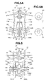
- FIGS. 5A and 5B are schematic illustrative views when a unit housing of the roller frictional transmission unit of FIG. 2 is deformed by a radial pressing reaction force between rollers.
- FIG. 5A is a schematic illustrative view showing the roller frictional transmission unit of FIG. 2 in a deformed state of the unit housing.
- FIG. 5B is a schematic illustrative view showing thrust load distribution to thrust bearings at the deformation of the unit housing.
- FIG. 6 is a schematic view showing a roller frictional transmission unit according to a second embodiment of the present invention.
- FIGS. 7A and 7B are schematic illustrative views when a unit housing of the roller frictional transmission unit of FIG. 6 is deformed by a radial pressing reaction force between rollers.
- FIG. 7A is a schematic illustrative view showing the roller frictional transmission unit of FIG. 6 .
- FIG. 7B is a schematic illustrative view showing thrust load distribution to thrust bearings at the deformation of the unit housing.
- FIG. 8 is a longitudinal sectional side view showing, as a main part, a thrust bearing support portion of a roller frictional transmission unit according to a third embodiment of the present invention.
- roller frictional transmission units 1 according to embodiments of the present invention are illustrated with reference to drawings.
- FIG. 1 is a schematic plan view from above a four wheel drive vehicle, showing a power train of the four wheel drive vehicle which is provided, as a transfer, with a roller frictional transmission unit 1 according to a first embodiment of the present invention.
- the four wheel drive vehicle of FIG. 1 is based on a rear wheel drive vehicle in which rotation from an engine 2 is shifted by a transmission 3, and then transmitted through a rear propeller shaft 4 and a rear final drive unit 5 to left and right rear wheels 6L and 6R, and constructed so that a part of torque to left and right rear wheels (main driving wheels) 6L and 6R is transmitted by roller frictional transmission unit 1 through a front propeller shaft 7 and a front final drive unit 8 to left and right front wheels (auxiliary driving wheels) 9L and 9R, thus achieving four wheel driving.
- Roller frictional transmission unit 1 is thus configured to split and output a part of torque to left and right rear wheels (the main driving wheels) 6L and 6R, to left and right front wheels (the auxiliary driving wheels) 9L and 9R, and thereby to set driving force distribution ratio between left and right rear wheels (the main driving wheels) 6L and 6R, and left and right front wheels (the auxiliary driving wheels) 9L and 9R.
- roller frictional transmission unit 1 is constructed as shown in FIG. 2 .
- a numeral 11 is a unit housing.
- An input shaft 12 and an output shaft 13 are disposed within unit housing 11 so that a rotational axis 01 of input shaft 12 and a rotational axis 02 of output shaft 13 are parallel with each other to laterally cross within unit housing 11.
- Input shaft 12 is rotatably supported by radial bearings 14 and 15 on side walls 11a and 11b of unit housing 11 so that input shaft 12 freely rotates about axis 01.
- Input shaft 12 includes both ends protruding from unit housing 11.
- the left end of input shaft 12 in FIG. 2 is connected through transmission 3 (cf. FIG. 1 ) to engine 2.
- the right end of input shaft 12 in FIG. 2 is connected through rear propeller shaft 4 (cf. FIG. 1 ) to rear final drive unit 5.
- Output shaft 13 is rotatably supported at both ends of output shaft 13 on side walls 11a and 11b of unit housing 11 by the following support structure.
- Crank shafts 16L and 16R of a hollow outer shaft type are freely mounted, respectively, between output shaft 13 and unit housing side walls 11a and 11b through which the both ends of output shaft 13 penetrate. These crank shafts 16L and 16R have the same specification.
- a radial bearing 17L is disposed between crank shaft 16L and unit housing side walls 11a and 11b. With this, crank shaft 16L is rotatably supported on an outer circumference surface 16Lb of crank shaft 16 by unit housing side walls 11a and 11b. Moreover, a radial bearing 17R is disposed between crank shaft 16R and unit housing side walls 11a and 11b. With this, crank shaft 16R is rotatably supported on an outer circumference surface 16Rb of crank shaft 16R by unit housing side walls 11a and 11b.
- a radial bearing 18L is disposed between crank shaft 16L and output shaft 13. With this, output shaft 13 is rotatably supported on an outer circumference surface of output shaft 13 within a hollow hole 16La of crank shaft 16L.
- a radial bearing 18R is disposed between crank shaft 16R and output shaft 13. With this, output shaft 13 is rotatably supported on the outer circumference surface of output shaft 13 within a hollow hole 16Ra of crank shaft 16R. Accordingly, output shaft 13 freely rotates about an axis 02 within hollow holes 16La and 16Ra of crank shaft 16L and 16R.
- output shaft 13 is rotatably supported, respectively, through crank shafts 16L and 16R within unit housing side walls 11a and 11b.
- Output shaft 13 supported within unit housing 11 includes a left end in FIG. 2 which protrudes from unit housing 11, and which is connected with front propeller shaft 7 (cf. FIG. 1 ). With this, the left end of output shaft 13 is connected with left and right front wheels 9L and 9R through front propeller shaft 7 and front final drive unit 8.
- Input shaft 12 is connected or molded integrally with a first roller 21 which is disposed at a substantially central portion of input shaft 12.
- Output shaft 13 is connected or molded integrally with a second roller 22 which is disposed at a substantially central portion of output shaft 13.
- First roller 21 and second roller 22 are disposed on the same plane perpendicular to the axes.
- Thrust bearings 23 are disposed, respectively, between unit housing side walls 11a and 11b, and the both sides of first roller 21 in the axial direction. Thrust bearings 23 position first roller 21 and input shaft 12 in the axial direction.
- a center 03 of outer circumference surfaces 16Lb and 16Rb (radius Ro) of crank shafts 16L and 16R are off (eccentric) from center 02 of crank shaft hollow holes 16La and 16Ra (radius Ri) by ⁇ .
- rotational axis 02 of output shaft 13 and second roller 22 rotates around rotational axis 03 by rotating crank shafts 16L and 16R around rotational axis 03 relative to unit housing 11. Consequently, it is possible to increase or decrease a radial pressing force of second roller 22 (outer circumference surface 22a) against first roller 21 (outer circumference surface 21a), and thereby to control contact frictional force (transmission torque capacity) between first roller 21 and second roller 22.
- Ring gears 16Lc and 16Rc having the same specification are integrally provided on adjacent ends of crank shafts 16L and 16R which confront each other, so as to perform the above-described rotational position control around rotational axis 03 of crank shafts 16L and 16R. These ring gears 16Lc and 16Rc are engaged with a common crank shaft drive pinion (not shown) having the same specification. This crank shaft drive pinion is connected with an inter-roller radial pressing force control motor.
- Ring gears 16Lc and 16Rc are engaged with the crank shaft drive pinion (not shown) so that crank shafts 16L and 16R are positioned in rotational positions in which eccentric outer circumference surfaces 16Lb and 16Rb of crank shafts 16L and 16R are arranged in the circumferential direction so as to be the same phase.
- Thrust bearings 24 are disposed, respectively, between ring gears 16Lc and 16Rc, and unit housing side walls 11a and 11b. Thrust bearings 25 are disposed, respectively, between second roller 22, and crank shafts 16L and 16R. These thrust bearings 24 and 25 position crank shafts 16L and 16R and second roller 22 (output shaft 13) with respect to unit housing 11 in the axial direction.
- the driving force distribution operation of the roller frictional transmission unit shown in FIGS. 1 and 2 according to the first embodiment is illustrated below.
- the output torque from transmission 3 in FIG. 1 is inputted into input shaft 12 from the left end in FIG. 2 .
- This output torque is transmitted directly through rear propeller shaft 4 and rear final drive unit 5 to left and right rear wheels 6L and 6R (the main driving wheels).
- roller frictional transmission unit 1 transmits a part of the torque to left and right rear wheels 6L and 6R from first roller 21 through second roller 22 to output shaft 13.
- the torque transmitted to output shaft 13 is transmitted from the left end of output shaft 13 in FIG. 2 through front propeller shaft 7 (cf. FIG. 1 ) and front final drive unit 8 to left and right front wheels (the auxiliary driving wheels) 9L and 9R.
- the vehicle can perform the four wheel driving by driving all of left and right rear wheels 6L and 6R (the main driving wheels) and left and right front wheels 9L and 9R (the auxiliary driving wheels).
- the driving force distribution control between left and right rear wheels 6L and 6R and left and right front wheels 9L and 9R at the four wheel driving is performed by rotating crank shafts 16L and 16R around axis 03 through ring gears 16Lc and 16Rc by the above-described inter-roller radial pressing force control motor (not shown). This control operation is performed in the following manner.
- Rotational axis 02 of output shaft 13 and second roller 22 is rotated around axis 03 by the rotation of crank shafts 16L and 16R around axis 03.
- the radial pressing force of second roller 22 against first roller 21, that is, the transmission torque capacity (the front and rear wheel driving force distribution) between rollers 21 and 22 is arbitrarily controlled by varying a distance between the axes of rollers 21 and 22, so that the driving force distribution control between left and right rear wheels 6L and 6R and left and right front wheels 9L and 9R is performed.
- housing 11 is elastically deformed when rollers 21 and 22 are pressed and contacted with each other in the radial direction, as described below.
- FIG. 3 shows a schematic view showing the roller frictional transmission unit of FIG. 2 .
- each of thrust bearings 23 positioning roller 21 receives a thrust load only in a circumferential region confronting one of unit housing side wall central portions 11c and 11d as shown by ⁇ in FIG. 4A
- each of thrust bearings 25 positioning roller 22 receives a thrust load only in a circumferential region confronting one of unit housing side wall central portions 11c and 11d as shown by ⁇ in FIG. 4A .
- thrust bearings 23 and 25 have high rigidity. Accordingly, the thrust load distribution to thrust bearings 23 and 25 are limited to extremely small regions of the above-described circumference region as shown by ⁇ and ⁇ in FIG. 4B . Accordingly, thrust bearings 23 and 25 receive the biased thrust load only in the extremely small circumferential regions. Therefore, the durability of thrust bearings 23 and 25 may be deteriorated by the large contact pressures.
- the roller frictional transmission unit according to the first embodiment has a below-described structure for solving the above-described problems relating to the durability of the thrust bearing without the weight increase and the cost increase.
- thrust buffering members 31 such as an elastic member are disposed, respectively, in thrust direction abutting portions between thrust bearings 23 and first roller 21, in which thrust bearings 23 and first roller 21 confront each other in the thrust direction.
- low rigidity structures for buffering the thrust are disposed, respectively, in the thrust transmissions path to thrust bearing 23.
- thrust buffering members 32 such as the elastic member are disposed, respectively, in thrust direction abutting portions between thrust bearings 25 and second roller 22, in which thrust bearings 25 and second roller 22 confront each other in the thrust direction.
- the low rigidity structures for buffering the thrust are disposed, respectively, in the thrust transmission paths to thrust bearings 25.
- the thrust load to thrust bearings 23 and 25 are buffered and dispersed by thrust buffering members 31 and 32 (the low rigidity structures for buffering the thrust).
- the areas of the circumference regions of thrust bearings 23 and 25 to which the thrust load are applied are ⁇ ′ and ⁇ ′ as shown in FIG. 5B , and are not the small areas ⁇ and ⁇ of the conventional apparatus as shown in FIG. 4B .
- thrust buffering members 31 and 32 such as the light-weight and low-cost elastic member are merely provided.
- FIG. 6 is a schematic diagram showing a roller frictional transmission unit according to a second embodiment of the present invention.
- the roller frictional transmission unit of FIG. 6 is substantially identical to the apparatus of FIGS. 2 and 5 in most aspects as shown by the use of the same reference numerals. Hereinafter, only different parts are illustrated.
- the following countermeasure is provided in place of thrust buffering members 31 and 32 in the first embodiment. That is, hollow portions 11k and 11m such as a slit which is a clearance in the thrust direction are formed, respectively, in thrust bearing support portions 11i and 11j of unit housing side walls 11a and 11b which constitute the thrust transmission paths to thrust bearings 23. With this, the low rigidity structures for buffering the thrust are disposed, respectively, in the thrust transmission paths to thrust bearings 23.
- hollow portions 11k and 11m are provided, respectively, only in the circumferential regions of thrust bearings 23 which receive the thrust in the compression direction by the above-described deformation of unit housing 11 when rollers 21 and 22 are pressed and contacted with each other in the radial direction.
- Hollow portions 11k and 11m are substantially semi-circular hollow portions which do not extend to the other circumference region.
- hollow portions 16Le and 16Re such as a slit which is a clearance in the thrust direction are formed, respectively, in thrust bearing support portions 16Ld and 16Rd of crank shafts 16L and 16R which constitute the thrust transmission paths to thrust bearings 25.
- the low rigidity structures for buffering the thrust are disposed, respectively, in the thrust transmission paths to thrust bearings 25.
- hollow portions 16Le and 16Re are provided, respectively, only in the circumferential regions of thrust bearing 25 which receive the thrust in the compression direction by the above-described deformation of unit housing 11 when rollers 21 and 22 are pressed and contacted with each other in the radial direction.
- Hollow portions 16Le and 16Re are substantially semi-circular hollow portions which do not extend to the other circumference region.
- the thrust load to thrust bearings 23 and 25 are buffered and dispersed by hollow portions 11k and 11m, and 16Le and 16Re (the low rigidity structure for buffering the thrust).
- the areas of the circumference regions of thrust bearings 23 and 25 to which the thrust load are applied are ⁇ ′ and ⁇ ′ as shown in FIG. 7B , and are not the small areas y and ⁇ of the conventional apparatus as shown in FIG. 4B .
- FIG. 8 is a schematic diagram showing support portions of thrust bearings 23 and 25 of a roller frictional transmission unit according to a third embodiment of the present invention.
- the roller frictional transmission unit of FIG. 8 is substantially identical to the apparatus of FIGS. 2 , 5, and 6 in most aspects as shown by the use of the same reference numerals. Hereinafter, only different parts are illustrated.
- the following countermeasure is provided in place of thrust buffering members 31 and 32 in the first embodiment, and hollow portions 11k and 11m, and 16Le and 16Re of the thrust bearing support portions in the second embodiment. That is, recessed portions 33 in the thrust direction are formed in thrust bearing support portions 11i and 11j of unit housing side walls 11a and 11b which constitute the thrust transmission paths to thrust bearings 23, at ends of thrust bearing support portions 11i and 11j which are abutted on thrust bearings 23 in the thrust direction (in the thrust direction abutting portions between thrust bearing support portions 11i and 11j and thrust bearings 23). With this, the low rigidity structures for buffering the thrust are disposed, respectively, in the thrust transmission paths to thrust bearings 23.
- recessed portions 34 in the thrust direction are formed, respectively, in thrust bearing support portions 16Ld and 16Rd of crank shafts 16L and 16R which constitute the thrust transmission path to thrust bearings 25, at ends of thrust bearing support portions 16Ld and 16Rd which are abutted on thrust bearings 25 in the thrust direction (in the thrust direction abutting portions between thrust bearing support portions 16Ld and 16Rd and thrust bearings 25).
- the low rigidity structures for buffering the thrust are disposed, respectively, in the thrust transmission paths to thrust bearings 25.
- recessed portions 33 and 34 are provided only in the circumferential regions of thrust bearings 23 and 25 which receive the thrust in the compression direction by the above-described deformation of unit housing 11 when rollers 21 and 22 are pressed and contacted with each other in the radial direction.
- Recessed portions 33 and 34 are substantially semi-circular recessed portions which do not extend to the other circumference region.
- the thrust load to thrust bearings 23 and 25 are buffered and dispersed by recessed portions 33 and 34 (the low rigidity structure for buffering the thrust). Accordingly, the areas of the circumference regions of thrust bearings 23 and 25 to which the thrust load are applied can be increased like ⁇ ′ and ⁇ ′ as shown in FIGS. 5B and 7B .
- thrust buffering members 31 are disposed, respectively, in the thrust direction abutting portion between thrust bearing 23 and first roller 21, and thrust buffering members 32 are disposed, respectively, in the thrust direction abutting portions between thrust bearings 25 and second roller 22.
- thrust buffering members 31 and 32 may be disposed on opposite sides of the thrust bearings 23 and 25 in the axial direction.
- thrust buffering members 31 and 32 may be disposed on both sides of thrust bearings 23 and 25.
- the thrust contact pressure decreasing countermeasures are provided to thrust bearing 23 on the input roller side, and thrust bearing 25 on the output roller side. Moreover, the thrust contact pressure decreasing countermeasure may be provided only to one of thrust bearings 23 and 25 which needs this countermeasure.
- a roller frictional transmission unit includes: a first roller; a second roller having an outer circumference surface arranged to be pressed and contacted with an outer circumference surface of the first roller to transmit a power between the first roller and the second roller by a friction; an input shaft connected with a driving system of main driving wheels of a four wheel drive vehicle, and connected with one of the first roller and the second roller; an output shaft connected with a driving system of auxiliary driving wheels of the four wheel drive vehicle, and connected with the other of the first roller and the second roller; a thrust bearing arranged to position an input shaft side rotation section including the one of the first roller and the second roller and the input shaft, or an output shaft side rotation section including the other of the first roller and the second roller and the output shaft, with respect to a unit housing in an axial direction; and a low rigidity structure disposed in a thrust transmission path to the thrust bearing, and arranged to buffer a thrust.
- the roller frictional transmission unit according to the present invention, the low rigidity structure for buffering the thrust is disposed in the thrust transmission path to the thrust bearing. Accordingly, the low rigidity structure buffers and disperse the thrust load to the thrust bearing. Even when the side wall of the unit housing is deformed by the curvature of the input shaft and/or the output shaft by the radial pressing reaction force between the rollers, the area of the circumferential region of the thrust bearing which receives the thrust load becomes large relative to the conventional apparatus.
Landscapes
- Engineering & Computer Science (AREA)
- General Engineering & Computer Science (AREA)
- Mechanical Engineering (AREA)
- Chemical & Material Sciences (AREA)
- Combustion & Propulsion (AREA)
- Transportation (AREA)
- Friction Gearing (AREA)
- Arrangement And Driving Of Transmission Devices (AREA)
Abstract

Description
- This invention relates to a roller frictional transmission unit used as a transfer of a four wheel drive vehicle, and more specifically to an art to improve a durability of a thrust bearing arranged to position a roller of the transmission unit in an axial direction.
-
U.S. Patent Application Publication No. 2010/0276246 A1 (corresponding to Japanese Patent Application Publication No.2009-173261 - In the roller frictional transmission unit, each of the rollers is positioned by thrust bearings disposed on both sides in an axial direction, with respect to a housing of the roller frictional transmission unit in the axial direction, so as to stably perform the frictional contact between the rollers.
- In the roller frictional transmission unit, when the rollers are pressed and contacted with each other in the radial direction, the shafts of the rollers (the input shaft and the output shaft) are curved in a direction to be away from each other within a bearing span. Accordingly, side walls of the unit housing supporting the shafts are deformed so that central portions of the unit housing side walls between the shafts are moved closer to each other, and so that both end portions of the unit housing side walls to sandwich the central portion of the unit housing side walls between the shafts are moved to be away from each other.
- This deformation of the unit housing limits thrust load distribution of the thrust bearings arranged to position the rollers in the axial direction, to extreme small circumferential regions of the thrust bearings confronting the unit housing side wall central portions which approach each other as described above.
- Accordingly, each of the thrust bearings receives the biased thrust load only at the extreme small circumferential region. Therefore, the durability of the thrust bearing is deteriorated by the large contact pressure.
- It is, therefore, an object of the present invention to provide a roller frictional transmission unit arranged to increase an area of a circumferential region to which the thrust load is applied relative to a conventional apparatus when a side wall of a unit housing is deformed, to decrease a contact pressure of a thrust bearing by a thrust load, and to solve the above mentioned problem of the durability of the thrust bearing.
- According to one aspect of the present invention, A roller frictional transmission unit comprises: a first roller; a second roller having an outer circumference surface arranged to be pressed and contacted with an outer circumference surface of the first roller to transmit a power between the first roller and the second roller by a friction; an input shaft connected with a driving system of main driving wheels of a four wheel drive vehicle, and connected with one of the first roller and the second roller; an output shaft connected with a driving system of auxiliary driving wheels of the four wheel drive vehicle, and connected with the other of the first roller and the second roller; a thrust bearing arranged to position an input shaft side rotation section including the one of the first roller and the second roller and the input shaft, or an output shaft side rotation section including the other of the first roller and the second roller and the output shaft, with respect to a unit housing in an axial direction; and a low rigidity structure disposed in a thrust transmission path to the thrust bearing, and arranged to buffer a thrust.
-
FIG. 1 is a schematic plan view from above a four wheel drive vehicle, showing a power train of the four wheel drive vehicle which is provided, as a transfer, with a roller frictional transmission unit according to a first embodiment of the present invention. -
FIG. 2 is a longitudinal sectional side view showing the roller frictional transmission unit ofFIG. 1 . -
FIG. 3 is a schematic view showing the roller frictional transmission unit ofFIG. 2 , in a state in which a main structure according to the present invention is removed. -
FIGS. 4A and 4B are illustrative views when a unit housing of the roller frictional transmission unit ofFIG. 3 is deformed by a radial pressing reaction force between rollers.FIG. 4A is an illustrative view showing a deformation state of the unit housing.FIG. 4B is an illustrative view showing thrust load distribution to thrust bearings at the deformation of the unit housing. -
FIGS. 5A and 5B are schematic illustrative views when a unit housing of the roller frictional transmission unit ofFIG. 2 is deformed by a radial pressing reaction force between rollers.FIG. 5A is a schematic illustrative view showing the roller frictional transmission unit ofFIG. 2 in a deformed state of the unit housing.FIG. 5B is a schematic illustrative view showing thrust load distribution to thrust bearings at the deformation of the unit housing. -
FIG. 6 is a schematic view showing a roller frictional transmission unit according to a second embodiment of the present invention. -
FIGS. 7A and 7B are schematic illustrative views when a unit housing of the roller frictional transmission unit ofFIG. 6 is deformed by a radial pressing reaction force between rollers.FIG. 7A is a schematic illustrative view showing the roller frictional transmission unit ofFIG. 6 .FIG. 7B is a schematic illustrative view showing thrust load distribution to thrust bearings at the deformation of the unit housing. -
FIG. 8 is a longitudinal sectional side view showing, as a main part, a thrust bearing support portion of a roller frictional transmission unit according to a third embodiment of the present invention. - Hereinafter, roller
frictional transmission units 1 according to embodiments of the present invention are illustrated with reference to drawings. -
FIG. 1 is a schematic plan view from above a four wheel drive vehicle, showing a power train of the four wheel drive vehicle which is provided, as a transfer, with a rollerfrictional transmission unit 1 according to a first embodiment of the present invention. - The four wheel drive vehicle of
FIG. 1 is based on a rear wheel drive vehicle in which rotation from anengine 2 is shifted by atransmission 3, and then transmitted through arear propeller shaft 4 and a rearfinal drive unit 5 to left and rightrear wheels frictional transmission unit 1 through afront propeller shaft 7 and a frontfinal drive unit 8 to left and right front wheels (auxiliary driving wheels) 9L and 9R, thus achieving four wheel driving. - Roller
frictional transmission unit 1 is thus configured to split and output a part of torque to left and right rear wheels (the main driving wheels) 6L and 6R, to left and right front wheels (the auxiliary driving wheels) 9L and 9R, and thereby to set driving force distribution ratio between left and right rear wheels (the main driving wheels) 6L and 6R, and left and right front wheels (the auxiliary driving wheels) 9L and 9R. In this embodiment, rollerfrictional transmission unit 1 is constructed as shown inFIG. 2 . - In
FIG. 2 , anumeral 11 is a unit housing. Aninput shaft 12 and anoutput shaft 13 are disposed withinunit housing 11 so that arotational axis 01 ofinput shaft 12 and arotational axis 02 ofoutput shaft 13 are parallel with each other to laterally cross withinunit housing 11.Input shaft 12 is rotatably supported byradial bearings side walls unit housing 11 so thatinput shaft 12 freely rotates aboutaxis 01.Input shaft 12 includes both ends protruding fromunit housing 11. The left end ofinput shaft 12 inFIG. 2 is connected through transmission 3 (cf.FIG. 1 ) toengine 2. The right end ofinput shaft 12 inFIG. 2 is connected through rear propeller shaft 4 (cf.FIG. 1 ) to rearfinal drive unit 5. -
Output shaft 13 is rotatably supported at both ends ofoutput shaft 13 onside walls unit housing 11 by the following support structure.Crank shafts output shaft 13 and unithousing side walls output shaft 13 penetrate. Thesecrank shafts - A radial bearing 17L is disposed between
crank shaft 16L and unithousing side walls crank shaft 16L is rotatably supported on an outer circumference surface 16Lb of crank shaft 16 by unithousing side walls crank shaft 16R and unithousing side walls crank shaft 16R is rotatably supported on an outer circumference surface 16Rb ofcrank shaft 16R by unithousing side walls - A radial bearing 18L is disposed between
crank shaft 16L andoutput shaft 13. With this,output shaft 13 is rotatably supported on an outer circumference surface ofoutput shaft 13 within a hollow hole 16La ofcrank shaft 16L. A radial bearing 18R is disposed betweencrank shaft 16R andoutput shaft 13. With this,output shaft 13 is rotatably supported on the outer circumference surface ofoutput shaft 13 within a hollow hole 16Ra ofcrank shaft 16R. Accordingly,output shaft 13 freely rotates about anaxis 02 within hollow holes 16La and 16Ra ofcrank shaft - By the above-described structure, the both ends of
output shaft 13 are rotatably supported, respectively, through crankshafts housing side walls Output shaft 13 supported withinunit housing 11 includes a left end inFIG. 2 which protrudes fromunit housing 11, and which is connected with front propeller shaft 7 (cf.FIG. 1 ). With this, the left end ofoutput shaft 13 is connected with left and rightfront wheels front propeller shaft 7 and frontfinal drive unit 8. -
Input shaft 12 is connected or molded integrally with afirst roller 21 which is disposed at a substantially central portion ofinput shaft 12.Output shaft 13 is connected or molded integrally with asecond roller 22 which is disposed at a substantially central portion ofoutput shaft 13.First roller 21 andsecond roller 22 are disposed on the same plane perpendicular to the axes.Thrust bearings 23 are disposed, respectively, between unithousing side walls first roller 21 in the axial direction.Thrust bearings 23 positionfirst roller 21 andinput shaft 12 in the axial direction. - A
center 03 of outer circumference surfaces 16Lb and 16Rb (radius Ro) of crankshafts center 02 of crank shaft hollow holes 16La and 16Ra (radius Ri) by ε. With this,rotational axis 02 ofoutput shaft 13 andsecond roller 22 rotates aroundrotational axis 03 by rotating crankshafts rotational axis 03 relative tounit housing 11. Consequently, it is possible to increase or decrease a radial pressing force of second roller 22 (outer circumference surface 22a) against first roller 21 (outer circumference surface 21a), and thereby to control contact frictional force (transmission torque capacity) betweenfirst roller 21 andsecond roller 22. - Ring gears 16Lc and 16Rc having the same specification are integrally provided on adjacent ends of crank
shafts rotational axis 03 of crankshafts - Ring gears 16Lc and 16Rc are engaged with the crank shaft drive pinion (not shown) so that crank
shafts crank shafts -
Thrust bearings 24 are disposed, respectively, between ring gears 16Lc and 16Rc, and unithousing side walls Thrust bearings 25 are disposed, respectively, betweensecond roller 22, and crankshafts thrust bearings shafts unit housing 11 in the axial direction. - <Driving Force Distribution Operation> The driving force distribution operation of the roller frictional transmission unit shown in
FIGS. 1 and2 according to the first embodiment is illustrated below.
The output torque fromtransmission 3 inFIG. 1 is inputted intoinput shaft 12 from the left end inFIG. 2 . This output torque is transmitted directly throughrear propeller shaft 4 and rearfinal drive unit 5 to left and rightrear wheels - On the other hand, roller
frictional transmission unit 1 transmits a part of the torque to left and rightrear wheels first roller 21 throughsecond roller 22 tooutput shaft 13. The torque transmitted tooutput shaft 13 is transmitted from the left end ofoutput shaft 13 inFIG. 2 through front propeller shaft 7 (cf.FIG. 1 ) and frontfinal drive unit 8 to left and right front wheels (the auxiliary driving wheels) 9L and 9R. - In this way, the vehicle can perform the four wheel driving by driving all of left and right
rear wheels front wheels rear wheels front wheels shafts axis 03 through ring gears 16Lc and 16Rc by the above-described inter-roller radial pressing force control motor (not shown). This control operation is performed in the following manner. -
Rotational axis 02 ofoutput shaft 13 andsecond roller 22 is rotated aroundaxis 03 by the rotation of crankshafts axis 03. With this, the radial pressing force ofsecond roller 22 againstfirst roller 21, that is, the transmission torque capacity (the front and rear wheel driving force distribution) betweenrollers rollers rear wheels front wheels - In the roller frictional transmission unit shown in
FIG. 2 ,housing 11 is elastically deformed whenrollers -
FIG. 3 shows a schematic view showing the roller frictional transmission unit ofFIG. 2 . Whenrollers input shaft 12 ofroller 21 andoutput shaft 13 ofroller 22 are brought from a straight state ofFIG. 3 to a curved state ofFIG. 4 thatinput shaft 12 andoutput shaft 13 are away from each other, respectively, in a bearing span betweenradial bearings 14 and 15 (cf.FIG. 2 ), and in a bearing span betweenradial bearings FIG. 2 ). - As shown in
FIG. 4A ,side walls unit housing 11 supporting theseshafts input shaft 12 andoutput shaft 13 so thatcentral portions housing side walls shafts end portions central portions - By the approach of unit housing side wall
central portions thrust bearings 23positioning roller 21 receives a thrust load only in a circumferential region confronting one of unit housing side wallcentral portions FIG. 4A , and each ofthrust bearings 25positioning roller 22 receives a thrust load only in a circumferential region confronting one of unit housing side wallcentral portions FIG. 4A . - Moreover, all of thrust transmission (transmitting) paths have high rigidity. Accordingly, the thrust load distribution to thrust
bearings FIG. 4B . Accordingly, thrustbearings thrust bearings - For dissolving this problem, it is conceivable that shaft diameters of
input shaft 12 andoutput shaft 13 are increased so as to suppress the curvatures ofinput shaft 12 andoutput shaft 13 which cause the above-described problem, and that thicknesses of unithousing side walls housing side walls - The roller frictional transmission unit according to the first embodiment has a below-described structure for solving the above-described problems relating to the durability of the thrust bearing without the weight increase and the cost increase.
- That is, as shown in
FIG. 2 andFIG. 5A , thrust bufferingmembers 31 such as an elastic member are disposed, respectively, in thrust direction abutting portions betweenthrust bearings 23 andfirst roller 21, in whichthrust bearings 23 andfirst roller 21 confront each other in the thrust direction. With this, low rigidity structures for buffering the thrust are disposed, respectively, in the thrust transmissions path to thrustbearing 23. Moreover, thrust bufferingmembers 32 such as the elastic member are disposed, respectively, in thrust direction abutting portions betweenthrust bearings 25 andsecond roller 22, in whichthrust bearings 25 andsecond roller 22 confront each other in the thrust direction. With this, the low rigidity structures for buffering the thrust are disposed, respectively, in the thrust transmission paths to thrustbearings 25. - In the roller frictional transmission unit according to the first embodiment, even when unit
housing side walls FIG. 5A by the cause described above with reference toFIG. 4A , the thrust load to thrustbearings thrust buffering members 31 and 32 (the low rigidity structures for buffering the thrust). The areas of the circumference regions ofthrust bearings FIG. 5B , and are not the small areas γ and δ of the conventional apparatus as shown inFIG. 4B . - Accordingly, it is possible to decrease the contact pressures of
thrust bearings thrust bearings thrust buffering members - Moreover, it is possible to increase the radial pressing force between the rollers without worrying about the durability of
thrust bearings thrust bearings -
FIG. 6 is a schematic diagram showing a roller frictional transmission unit according to a second embodiment of the present invention. The roller frictional transmission unit ofFIG. 6 is substantially identical to the apparatus ofFIGS. 2 and5 in most aspects as shown by the use of the same reference numerals. Hereinafter, only different parts are illustrated. - In the roller frictional transmission unit according to the second embodiment, the following countermeasure is provided in place of
thrust buffering members hollow portions support portions housing side walls bearings 23. With this, the low rigidity structures for buffering the thrust are disposed, respectively, in the thrust transmission paths to thrustbearings 23. - However,
hollow portions thrust bearings 23 which receive the thrust in the compression direction by the above-described deformation ofunit housing 11 whenrollers Hollow portions - Moreover, hollow portions 16Le and 16Re such as a slit which is a clearance in the thrust direction are formed, respectively, in thrust bearing support portions 16Ld and 16Rd of
crank shafts bearings 25. With this, the low rigidity structures for buffering the thrust are disposed, respectively, in the thrust transmission paths to thrustbearings 25. - However, hollow portions 16Le and 16Re are provided, respectively, only in the circumferential regions of thrust bearing 25 which receive the thrust in the compression direction by the above-described deformation of
unit housing 11 whenrollers - In the roller frictional transmission unit according to the second embodiment, even when unit
housing side walls FIG. 7A by the cause described above with reference toFIG. 4A , the thrust load to thrustbearings hollow portions thrust bearings FIG. 7B , and are not the small areas y and δ of the conventional apparatus as shown inFIG. 4B . - Accordingly, it is possible to decrease the contact pressures of
thrust bearings thrust bearings hollow portions support portions housing side walls crank shafts - Moreover, it is possible to increase the radial pressing force between the rollers without worrying about the durability of
thrust bearings thrust bearings -
FIG. 8 is a schematic diagram showing support portions ofthrust bearings FIG. 8 is substantially identical to the apparatus ofFIGS. 2 ,5, and 6 in most aspects as shown by the use of the same reference numerals. Hereinafter, only different parts are illustrated. - In the roller frictional transmission unit according to the third embodiment, the following countermeasure is provided in place of
thrust buffering members hollow portions portions 33 in the thrust direction are formed in thrust bearingsupport portions housing side walls bearings 23, at ends of thrust bearingsupport portions thrust bearings 23 in the thrust direction (in the thrust direction abutting portions between thrust bearingsupport portions bearings 23. - Moreover, recessed
portions 34 in the thrust direction are formed, respectively, in thrust bearing support portions 16Ld and 16Rd ofcrank shafts bearings 25, at ends of thrust bearing support portions 16Ld and 16Rd which are abutted onthrust bearings 25 in the thrust direction (in the thrust direction abutting portions between thrust bearing support portions 16Ld and 16Rd and thrust bearings 25). With this, the low rigidity structures for buffering the thrust are disposed, respectively, in the thrust transmission paths to thrustbearings 25. - However, recessed
portions thrust bearings unit housing 11 whenrollers portions - In the roller frictional transmission unit according to the third embodiment, even when unit
housing side walls FIG. 4A , the thrust load to thrustbearings portions 33 and 34 (the low rigidity structure for buffering the thrust). Accordingly, the areas of the circumference regions ofthrust bearings FIGS. 5B and7B . - Therefore, it is possible to decrease the contact pressures of
thrust bearings thrust bearings portions support portions - Moreover, it is possible to increase the radial pressing force between the rollers without worrying about the durability of
thrust bearings thrust bearings - In the first embodiment, as shown in
FIG. 2 andFIG. 5A , thrust bufferingmembers 31 are disposed, respectively, in the thrust direction abutting portion between thrust bearing 23 andfirst roller 21, and thrust bufferingmembers 32 are disposed, respectively, in the thrust direction abutting portions betweenthrust bearings 25 andsecond roller 22. Moreover, thrust bufferingmembers thrust bearings members thrust bearings - In the roller frictional transmission unit according to the first to third embodiments, the thrust contact pressure decreasing countermeasures are provided to thrust
bearing 23 on the input roller side, and thrustbearing 25 on the output roller side. Moreover, the thrust contact pressure decreasing countermeasure may be provided only to one ofthrust bearings - A roller frictional transmission unit according to the present invention includes: a first roller; a second roller having an outer circumference surface arranged to be pressed and contacted with an outer circumference surface of the first roller to transmit a power between the first roller and the second roller by a friction; an input shaft connected with a driving system of main driving wheels of a four wheel drive vehicle, and connected with one of the first roller and the second roller; an output shaft connected with a driving system of auxiliary driving wheels of the four wheel drive vehicle, and connected with the other of the first roller and the second roller; a thrust bearing arranged to position an input shaft side rotation section including the one of the first roller and the second roller and the input shaft, or an output shaft side rotation section including the other of the first roller and the second roller and the output shaft, with respect to a unit housing in an axial direction; and a low rigidity structure disposed in a thrust transmission path to the thrust bearing, and arranged to buffer a thrust.
- In this way, the roller frictional transmission unit according to the present invention, the low rigidity structure for buffering the thrust is disposed in the thrust transmission path to the thrust bearing. Accordingly, the low rigidity structure buffers and disperse the thrust load to the thrust bearing. Even when the side wall of the unit housing is deformed by the curvature of the input shaft and/or the output shaft by the radial pressing reaction force between the rollers, the area of the circumferential region of the thrust bearing which receives the thrust load becomes large relative to the conventional apparatus.
- Accordingly, it is possible to decrease the contact pressure of the thrust bearing by the thrust load, and to solve the problem to decrease the durability of the thrust bearing.
- The entire contents of Japanese Patent Application No.
2010-274249 filed December 9, 2010 - Although the invention has been described above by reference to certain embodiments of the invention, the invention is not limited to the embodiments described above. Modifications and variations of the embodiments described above will occur to those skilled in the art in light of the above teachings. The scope of the invention is defined with reference to the following claims.
Claims (5)
- A roller frictional transmission unit comprising:a first roller (21);a second roller (22) having an outer circumference surface arranged to be pressed and contacted with an outer circumference surface of the first roller (21) to transmit a power between the first roller (21) and the second roller (22) by a friction;an input shaft (12) connected with a driving system of main driving wheels (6L, 6R) of a four wheel drive vehicle, and connected with one of the first roller (21) and the second roller (22);an output shaft (13) connected with a driving system of auxiliary driving wheels (9L, 9R) of the four wheel drive vehicle, and connected with the other of the first roller (21) and the second roller (22);a thrust bearing (23, 25) arranged to position an input shaft side rotation section including the one of the first roller (21) and the second roller (22) and the input shaft (12), or an output shaft side rotation section including the other of the first roller (21) and the second roller (22) and the output shaft (13), with respect to a unit housing (11) in an axial direction; anda low rigidity structure (31, 32; 11k, 11m, 16Le, 16Re; 33, 34) disposed in a thrust transmission path to the thrust bearing (23, 25), and arranged to buffer a thrust.
- The roller frictional transmission unit as claimed in Claim 1, wherein the thrust transmission path in which the low rigidity structure (31, 32; 11k, 11m, 16Le, 16Re; 33, 34) is disposed is a thrust transmission path to a circumferential region of the thrust bearing which receives the thrust in a compression direction by a deformation of the unit housing (11) when the first roller (21) and the second roller (22) are pressed and contacted with each other in a radial direction.
- The roller frictional transmission unit as claimed in Claim 1 or 2, wherein the low rigidity structure is a thrust buffering member (31, 32) disposed on one side of the thrust bearing (23, 25) in the axial direction.
- The roller frictional transmission unit as claimed in Claim 1 or 2, wherein the low rigidity structure is a hollow portion (11k, 11m, 16Le, 16Re) formed in a thrust bearing support portion (11i, 11j, 16Ld, 16Rd) which is the thrust transmission path.
- The roller frictional transmission unit as claimed in Claim 1 or 2, wherein the low rigidity structure is a recessed portion (33, 34) which is formed in a thrust bearing support portion (11i, 11j, 16Ld, 16Rd) which is the thrust transmission path; and the recessed portion (33, 34) is formed in a thrust direction at an end of the thrust bearing support portion (11i, 11j, 16Ld, 16Rd) which is abutted on the thrust bearing (23, 25) in the thrust direction.
Applications Claiming Priority (1)
| Application Number | Priority Date | Filing Date | Title |
|---|---|---|---|
| JP2010274249A JP5644455B2 (en) | 2010-12-09 | 2010-12-09 | Roller friction transmission unit |
Publications (2)
| Publication Number | Publication Date |
|---|---|
| EP2463535A1 true EP2463535A1 (en) | 2012-06-13 |
| EP2463535B1 EP2463535B1 (en) | 2013-06-05 |
Family
ID=45315590
Family Applications (1)
| Application Number | Title | Priority Date | Filing Date |
|---|---|---|---|
| EP11192499.9A Not-in-force EP2463535B1 (en) | 2010-12-09 | 2011-12-08 | Roller frictional transmission unit |
Country Status (4)
| Country | Link |
|---|---|
| US (1) | US8579757B2 (en) |
| EP (1) | EP2463535B1 (en) |
| JP (1) | JP5644455B2 (en) |
| CN (1) | CN102537246B (en) |
Families Citing this family (5)
| Publication number | Priority date | Publication date | Assignee | Title |
|---|---|---|---|---|
| JP5262588B2 (en) * | 2007-12-26 | 2013-08-14 | 日産自動車株式会社 | Driving force distribution device |
| BRPI0805746B1 (en) * | 2008-10-02 | 2020-06-09 | Luis Andre Parise | continuous transition exchange - ctc |
| JP5326866B2 (en) * | 2009-06-30 | 2013-10-30 | 日産自動車株式会社 | Traction transmission capacity controller for driving force distribution device |
| JP5817104B2 (en) * | 2010-11-18 | 2015-11-18 | 日産自動車株式会社 | Roller friction transmission unit |
| US20140013902A1 (en) * | 2012-07-10 | 2014-01-16 | Nissan Motor Co., Ltd. | Drive force distributing apparatus |
Citations (2)
| Publication number | Priority date | Publication date | Assignee | Title |
|---|---|---|---|---|
| JP2009173261A (en) | 2007-12-26 | 2009-08-06 | Nissan Motor Co Ltd | Driving force distribution device |
| JP2010274249A (en) | 2009-06-01 | 2010-12-09 | Tsutomu Katsura | nozzle |
Family Cites Families (16)
| Publication number | Priority date | Publication date | Assignee | Title |
|---|---|---|---|---|
| US4322798A (en) * | 1978-02-16 | 1982-03-30 | Bales-Mccoin Research, Inc. | Traction pressure control system |
| JPS5981296A (en) * | 1982-10-29 | 1984-05-10 | Nippon Pillar Packing Co Ltd | Thrust bearing device of vessel rudder shaft |
| US4555963A (en) * | 1983-11-17 | 1985-12-03 | Wedgtrac Corporation | Torque limit drive transmission |
| US7118512B2 (en) * | 2000-09-08 | 2006-10-10 | Iowa State University Research Foundation, Inc. | Self-actuating, traction-drive speed changer |
| US6524214B1 (en) * | 2000-12-27 | 2003-02-25 | James A. Cillessen | Variable ratio transmission |
| US6849025B2 (en) * | 2001-04-09 | 2005-02-01 | Nsk Ltd. | Frictional roller transmission |
| US6840886B2 (en) * | 2002-03-29 | 2005-01-11 | Matsushita Electric Industrial Co., Ltd. | Method and apparatus for a low cost, high speed, and compact nanometer precision motion stage using friction drive and flexure hinge |
| WO2004070233A1 (en) * | 2003-02-10 | 2004-08-19 | Ntn Corporation | Traction drive type continuously variable transmission |
| WO2006064328A1 (en) * | 2004-12-15 | 2006-06-22 | Cid, Centro De Investigacion Y Desarrollo Tecnologico, S.A. De C.V. | Self-adjustable tractive planetary gear transmission |
| JP4765453B2 (en) * | 2005-07-20 | 2011-09-07 | 日産自動車株式会社 | Friction transmission |
| JP4816093B2 (en) * | 2006-01-16 | 2011-11-16 | 日産自動車株式会社 | Friction transmission |
| JP4687581B2 (en) * | 2006-06-23 | 2011-05-25 | パナソニック株式会社 | Hermetic compressor |
| JP4694520B2 (en) * | 2007-03-07 | 2011-06-08 | 日産自動車株式会社 | Friction transmission |
| JP5263173B2 (en) * | 2008-01-23 | 2013-08-14 | 日産自動車株式会社 | Friction roller transmission |
| JP5120200B2 (en) * | 2008-10-27 | 2013-01-16 | パナソニック株式会社 | Hermetic compressor |
| JP5326676B2 (en) * | 2009-03-07 | 2013-10-30 | 日産自動車株式会社 | Friction transmission |
-
2010
- 2010-12-09 JP JP2010274249A patent/JP5644455B2/en not_active Expired - Fee Related
-
2011
- 2011-12-02 US US13/309,635 patent/US8579757B2/en not_active Expired - Fee Related
- 2011-12-02 CN CN201110395071.2A patent/CN102537246B/en not_active Expired - Fee Related
- 2011-12-08 EP EP11192499.9A patent/EP2463535B1/en not_active Not-in-force
Patent Citations (4)
| Publication number | Priority date | Publication date | Assignee | Title |
|---|---|---|---|---|
| JP2009173261A (en) | 2007-12-26 | 2009-08-06 | Nissan Motor Co Ltd | Driving force distribution device |
| EP2236341A1 (en) * | 2007-12-26 | 2010-10-06 | Nissan Motor Co., Ltd. | Driving force distribution device |
| US20100276246A1 (en) | 2007-12-26 | 2010-11-04 | Nissan Motor Co., Ltd. | Driving force distribution device |
| JP2010274249A (en) | 2009-06-01 | 2010-12-09 | Tsutomu Katsura | nozzle |
Also Published As
| Publication number | Publication date |
|---|---|
| CN102537246A (en) | 2012-07-04 |
| US20120149529A1 (en) | 2012-06-14 |
| JP5644455B2 (en) | 2014-12-24 |
| CN102537246B (en) | 2015-06-17 |
| JP2012121473A (en) | 2012-06-28 |
| EP2463535B1 (en) | 2013-06-05 |
| US8579757B2 (en) | 2013-11-12 |
Similar Documents
| Publication | Publication Date | Title |
|---|---|---|
| EP2463535B1 (en) | Roller frictional transmission unit | |
| JP5263173B2 (en) | Friction roller transmission | |
| JP5024391B2 (en) | Friction roller transmission | |
| US9200698B2 (en) | Roller-type friction transmission unit | |
| EP2405158B1 (en) | Friction gearing | |
| US20120264557A1 (en) | Torque distributor | |
| JP2010196793A (en) | Friction transmission device and driving force distribution device using the same | |
| JP2014040892A (en) | Frictional roller type transmission | |
| US9903449B2 (en) | Toroidal continuously variable transmission | |
| JP4941279B2 (en) | Friction roller support structure of friction transmission device | |
| JP5761445B2 (en) | Continuously variable transmission | |
| JP3899761B2 (en) | Toroidal continuously variable transmission | |
| JP2019168047A (en) | Stepless speed change device | |
| CN119343540A (en) | Tripod universal joint | |
| WO2008059807A1 (en) | Transmission mechanism |
Legal Events
| Date | Code | Title | Description |
|---|---|---|---|
| PUAI | Public reference made under article 153(3) epc to a published international application that has entered the european phase |
Free format text: ORIGINAL CODE: 0009012 |
|
| 17P | Request for examination filed |
Effective date: 20111208 |
|
| AK | Designated contracting states |
Kind code of ref document: A1 Designated state(s): AL AT BE BG CH CY CZ DE DK EE ES FI FR GB GR HR HU IE IS IT LI LT LU LV MC MK MT NL NO PL PT RO RS SE SI SK SM TR |
|
| AX | Request for extension of the european patent |
Extension state: BA ME |
|
| GRAP | Despatch of communication of intention to grant a patent |
Free format text: ORIGINAL CODE: EPIDOSNIGR1 |
|
| RIC1 | Information provided on ipc code assigned before grant |
Ipc: B60K 17/344 20060101ALI20121128BHEP Ipc: F16H 13/00 20060101ALI20121128BHEP Ipc: F16C 19/30 20060101AFI20121128BHEP |
|
| GRAS | Grant fee paid |
Free format text: ORIGINAL CODE: EPIDOSNIGR3 |
|
| GRAA | (expected) grant |
Free format text: ORIGINAL CODE: 0009210 |
|
| AK | Designated contracting states |
Kind code of ref document: B1 Designated state(s): AL AT BE BG CH CY CZ DE DK EE ES FI FR GB GR HR HU IE IS IT LI LT LU LV MC MK MT NL NO PL PT RO RS SE SI SK SM TR |
|
| REG | Reference to a national code |
Ref country code: GB Ref legal event code: FG4D |
|
| REG | Reference to a national code |
Ref country code: CH Ref legal event code: EP |
|
| REG | Reference to a national code |
Ref country code: AT Ref legal event code: REF Ref document number: 615831 Country of ref document: AT Kind code of ref document: T Effective date: 20130615 |
|
| REG | Reference to a national code |
Ref country code: IE Ref legal event code: FG4D |
|
| REG | Reference to a national code |
Ref country code: DE Ref legal event code: R096 Ref document number: 602011001941 Country of ref document: DE Effective date: 20130801 |
|
| REG | Reference to a national code |
Ref country code: AT Ref legal event code: MK05 Ref document number: 615831 Country of ref document: AT Kind code of ref document: T Effective date: 20130605 |
|
| PG25 | Lapsed in a contracting state [announced via postgrant information from national office to epo] |
Ref country code: FI Free format text: LAPSE BECAUSE OF FAILURE TO SUBMIT A TRANSLATION OF THE DESCRIPTION OR TO PAY THE FEE WITHIN THE PRESCRIBED TIME-LIMIT Effective date: 20130605 Ref country code: SI Free format text: LAPSE BECAUSE OF FAILURE TO SUBMIT A TRANSLATION OF THE DESCRIPTION OR TO PAY THE FEE WITHIN THE PRESCRIBED TIME-LIMIT Effective date: 20130605 Ref country code: LT Free format text: LAPSE BECAUSE OF FAILURE TO SUBMIT A TRANSLATION OF THE DESCRIPTION OR TO PAY THE FEE WITHIN THE PRESCRIBED TIME-LIMIT Effective date: 20130605 Ref country code: NO Free format text: LAPSE BECAUSE OF FAILURE TO SUBMIT A TRANSLATION OF THE DESCRIPTION OR TO PAY THE FEE WITHIN THE PRESCRIBED TIME-LIMIT Effective date: 20130905 Ref country code: ES Free format text: LAPSE BECAUSE OF FAILURE TO SUBMIT A TRANSLATION OF THE DESCRIPTION OR TO PAY THE FEE WITHIN THE PRESCRIBED TIME-LIMIT Effective date: 20130916 Ref country code: GR Free format text: LAPSE BECAUSE OF FAILURE TO SUBMIT A TRANSLATION OF THE DESCRIPTION OR TO PAY THE FEE WITHIN THE PRESCRIBED TIME-LIMIT Effective date: 20130906 Ref country code: AT Free format text: LAPSE BECAUSE OF FAILURE TO SUBMIT A TRANSLATION OF THE DESCRIPTION OR TO PAY THE FEE WITHIN THE PRESCRIBED TIME-LIMIT Effective date: 20130605 Ref country code: SE Free format text: LAPSE BECAUSE OF FAILURE TO SUBMIT A TRANSLATION OF THE DESCRIPTION OR TO PAY THE FEE WITHIN THE PRESCRIBED TIME-LIMIT Effective date: 20130605 |
|
| REG | Reference to a national code |
Ref country code: NL Ref legal event code: VDEP Effective date: 20130605 |
|
| REG | Reference to a national code |
Ref country code: LT Ref legal event code: MG4D |
|
| PG25 | Lapsed in a contracting state [announced via postgrant information from national office to epo] |
Ref country code: BG Free format text: LAPSE BECAUSE OF FAILURE TO SUBMIT A TRANSLATION OF THE DESCRIPTION OR TO PAY THE FEE WITHIN THE PRESCRIBED TIME-LIMIT Effective date: 20130905 Ref country code: HR Free format text: LAPSE BECAUSE OF FAILURE TO SUBMIT A TRANSLATION OF THE DESCRIPTION OR TO PAY THE FEE WITHIN THE PRESCRIBED TIME-LIMIT Effective date: 20130605 Ref country code: RS Free format text: LAPSE BECAUSE OF FAILURE TO SUBMIT A TRANSLATION OF THE DESCRIPTION OR TO PAY THE FEE WITHIN THE PRESCRIBED TIME-LIMIT Effective date: 20130605 |
|
| PG25 | Lapsed in a contracting state [announced via postgrant information from national office to epo] |
Ref country code: LV Free format text: LAPSE BECAUSE OF FAILURE TO SUBMIT A TRANSLATION OF THE DESCRIPTION OR TO PAY THE FEE WITHIN THE PRESCRIBED TIME-LIMIT Effective date: 20130605 |
|
| PG25 | Lapsed in a contracting state [announced via postgrant information from national office to epo] |
Ref country code: BE Free format text: LAPSE BECAUSE OF FAILURE TO SUBMIT A TRANSLATION OF THE DESCRIPTION OR TO PAY THE FEE WITHIN THE PRESCRIBED TIME-LIMIT Effective date: 20130605 Ref country code: SK Free format text: LAPSE BECAUSE OF FAILURE TO SUBMIT A TRANSLATION OF THE DESCRIPTION OR TO PAY THE FEE WITHIN THE PRESCRIBED TIME-LIMIT Effective date: 20130605 Ref country code: EE Free format text: LAPSE BECAUSE OF FAILURE TO SUBMIT A TRANSLATION OF THE DESCRIPTION OR TO PAY THE FEE WITHIN THE PRESCRIBED TIME-LIMIT Effective date: 20130605 Ref country code: IS Free format text: LAPSE BECAUSE OF FAILURE TO SUBMIT A TRANSLATION OF THE DESCRIPTION OR TO PAY THE FEE WITHIN THE PRESCRIBED TIME-LIMIT Effective date: 20131005 Ref country code: CZ Free format text: LAPSE BECAUSE OF FAILURE TO SUBMIT A TRANSLATION OF THE DESCRIPTION OR TO PAY THE FEE WITHIN THE PRESCRIBED TIME-LIMIT Effective date: 20130605 Ref country code: PT Free format text: LAPSE BECAUSE OF FAILURE TO SUBMIT A TRANSLATION OF THE DESCRIPTION OR TO PAY THE FEE WITHIN THE PRESCRIBED TIME-LIMIT Effective date: 20131007 |
|
| PG25 | Lapsed in a contracting state [announced via postgrant information from national office to epo] |
Ref country code: NL Free format text: LAPSE BECAUSE OF FAILURE TO SUBMIT A TRANSLATION OF THE DESCRIPTION OR TO PAY THE FEE WITHIN THE PRESCRIBED TIME-LIMIT Effective date: 20130605 Ref country code: RO Free format text: LAPSE BECAUSE OF FAILURE TO SUBMIT A TRANSLATION OF THE DESCRIPTION OR TO PAY THE FEE WITHIN THE PRESCRIBED TIME-LIMIT Effective date: 20130605 Ref country code: PL Free format text: LAPSE BECAUSE OF FAILURE TO SUBMIT A TRANSLATION OF THE DESCRIPTION OR TO PAY THE FEE WITHIN THE PRESCRIBED TIME-LIMIT Effective date: 20130605 |
|
| PLBE | No opposition filed within time limit |
Free format text: ORIGINAL CODE: 0009261 |
|
| STAA | Information on the status of an ep patent application or granted ep patent |
Free format text: STATUS: NO OPPOSITION FILED WITHIN TIME LIMIT |
|
| PG25 | Lapsed in a contracting state [announced via postgrant information from national office to epo] |
Ref country code: DK Free format text: LAPSE BECAUSE OF FAILURE TO SUBMIT A TRANSLATION OF THE DESCRIPTION OR TO PAY THE FEE WITHIN THE PRESCRIBED TIME-LIMIT Effective date: 20130605 |
|
| 26N | No opposition filed |
Effective date: 20140306 |
|
| PG25 | Lapsed in a contracting state [announced via postgrant information from national office to epo] |
Ref country code: IT Free format text: LAPSE BECAUSE OF FAILURE TO SUBMIT A TRANSLATION OF THE DESCRIPTION OR TO PAY THE FEE WITHIN THE PRESCRIBED TIME-LIMIT Effective date: 20130605 |
|
| REG | Reference to a national code |
Ref country code: DE Ref legal event code: R097 Ref document number: 602011001941 Country of ref document: DE Effective date: 20140306 |
|
| PG25 | Lapsed in a contracting state [announced via postgrant information from national office to epo] |
Ref country code: MC Free format text: LAPSE BECAUSE OF FAILURE TO SUBMIT A TRANSLATION OF THE DESCRIPTION OR TO PAY THE FEE WITHIN THE PRESCRIBED TIME-LIMIT Effective date: 20130605 |
|
| PG25 | Lapsed in a contracting state [announced via postgrant information from national office to epo] |
Ref country code: LU Free format text: LAPSE BECAUSE OF FAILURE TO SUBMIT A TRANSLATION OF THE DESCRIPTION OR TO PAY THE FEE WITHIN THE PRESCRIBED TIME-LIMIT Effective date: 20131208 |
|
| REG | Reference to a national code |
Ref country code: IE Ref legal event code: MM4A |
|
| PG25 | Lapsed in a contracting state [announced via postgrant information from national office to epo] |
Ref country code: IE Free format text: LAPSE BECAUSE OF NON-PAYMENT OF DUE FEES Effective date: 20131208 |
|
| PG25 | Lapsed in a contracting state [announced via postgrant information from national office to epo] |
Ref country code: SM Free format text: LAPSE BECAUSE OF FAILURE TO SUBMIT A TRANSLATION OF THE DESCRIPTION OR TO PAY THE FEE WITHIN THE PRESCRIBED TIME-LIMIT Effective date: 20130605 |
|
| PG25 | Lapsed in a contracting state [announced via postgrant information from national office to epo] |
Ref country code: CY Free format text: LAPSE BECAUSE OF FAILURE TO SUBMIT A TRANSLATION OF THE DESCRIPTION OR TO PAY THE FEE WITHIN THE PRESCRIBED TIME-LIMIT Effective date: 20130605 Ref country code: TR Free format text: LAPSE BECAUSE OF FAILURE TO SUBMIT A TRANSLATION OF THE DESCRIPTION OR TO PAY THE FEE WITHIN THE PRESCRIBED TIME-LIMIT Effective date: 20130605 |
|
| PG25 | Lapsed in a contracting state [announced via postgrant information from national office to epo] |
Ref country code: MK Free format text: LAPSE BECAUSE OF FAILURE TO SUBMIT A TRANSLATION OF THE DESCRIPTION OR TO PAY THE FEE WITHIN THE PRESCRIBED TIME-LIMIT Effective date: 20130605 Ref country code: HU Free format text: LAPSE BECAUSE OF FAILURE TO SUBMIT A TRANSLATION OF THE DESCRIPTION OR TO PAY THE FEE WITHIN THE PRESCRIBED TIME-LIMIT; INVALID AB INITIO Effective date: 20111208 |
|
| REG | Reference to a national code |
Ref country code: CH Ref legal event code: PL |
|
| PG25 | Lapsed in a contracting state [announced via postgrant information from national office to epo] |
Ref country code: MT Free format text: LAPSE BECAUSE OF FAILURE TO SUBMIT A TRANSLATION OF THE DESCRIPTION OR TO PAY THE FEE WITHIN THE PRESCRIBED TIME-LIMIT Effective date: 20130605 |
|
| PG25 | Lapsed in a contracting state [announced via postgrant information from national office to epo] |
Ref country code: CH Free format text: LAPSE BECAUSE OF NON-PAYMENT OF DUE FEES Effective date: 20141231 Ref country code: LI Free format text: LAPSE BECAUSE OF NON-PAYMENT OF DUE FEES Effective date: 20141231 |
|
| REG | Reference to a national code |
Ref country code: FR Ref legal event code: PLFP Year of fee payment: 5 |
|
| PGFP | Annual fee paid to national office [announced via postgrant information from national office to epo] |
Ref country code: GB Payment date: 20151202 Year of fee payment: 5 Ref country code: DE Payment date: 20151201 Year of fee payment: 5 |
|
| PGFP | Annual fee paid to national office [announced via postgrant information from national office to epo] |
Ref country code: FR Payment date: 20151110 Year of fee payment: 5 |
|
| REG | Reference to a national code |
Ref country code: DE Ref legal event code: R119 Ref document number: 602011001941 Country of ref document: DE |
|
| GBPC | Gb: european patent ceased through non-payment of renewal fee |
Effective date: 20161208 |
|
| REG | Reference to a national code |
Ref country code: FR Ref legal event code: ST Effective date: 20170831 |
|
| PG25 | Lapsed in a contracting state [announced via postgrant information from national office to epo] |
Ref country code: FR Free format text: LAPSE BECAUSE OF NON-PAYMENT OF DUE FEES Effective date: 20170102 |
|
| PG25 | Lapsed in a contracting state [announced via postgrant information from national office to epo] |
Ref country code: DE Free format text: LAPSE BECAUSE OF NON-PAYMENT OF DUE FEES Effective date: 20170701 Ref country code: GB Free format text: LAPSE BECAUSE OF NON-PAYMENT OF DUE FEES Effective date: 20161208 |
|
| PG25 | Lapsed in a contracting state [announced via postgrant information from national office to epo] |
Ref country code: AL Free format text: LAPSE BECAUSE OF FAILURE TO SUBMIT A TRANSLATION OF THE DESCRIPTION OR TO PAY THE FEE WITHIN THE PRESCRIBED TIME-LIMIT Effective date: 20130605 |