EP2463002B1 - Toy vehicle - Google Patents
Toy vehicle Download PDFInfo
- Publication number
- EP2463002B1 EP2463002B1 EP11166343.1A EP11166343A EP2463002B1 EP 2463002 B1 EP2463002 B1 EP 2463002B1 EP 11166343 A EP11166343 A EP 11166343A EP 2463002 B1 EP2463002 B1 EP 2463002B1
- Authority
- EP
- European Patent Office
- Prior art keywords
- vehicle
- wheels
- wheel
- remote control
- orientation
- Prior art date
- Legal status (The legal status is an assumption and is not a legal conclusion. Google has not performed a legal analysis and makes no representation as to the accuracy of the status listed.)
- Not-in-force
Links
- 230000008859 change Effects 0.000 claims description 8
- 230000033001 locomotion Effects 0.000 claims description 8
- 239000000463 material Substances 0.000 claims description 7
- 230000009471 action Effects 0.000 claims description 5
- 230000008878 coupling Effects 0.000 claims description 4
- 238000010168 coupling process Methods 0.000 claims description 4
- 238000005859 coupling reaction Methods 0.000 claims description 4
- 230000001105 regulatory effect Effects 0.000 claims description 2
- 230000011664 signaling Effects 0.000 claims 1
- 230000000712 assembly Effects 0.000 description 7
- 238000000429 assembly Methods 0.000 description 7
- 230000007246 mechanism Effects 0.000 description 4
- 230000002441 reversible effect Effects 0.000 description 4
- 230000035939 shock Effects 0.000 description 4
- 239000000725 suspension Substances 0.000 description 3
- 229910012258 LiPO Inorganic materials 0.000 description 2
- 239000006260 foam Substances 0.000 description 2
- 230000009191 jumping Effects 0.000 description 2
- 238000000034 method Methods 0.000 description 2
- 239000004033 plastic Substances 0.000 description 2
- RVCKCEDKBVEEHL-UHFFFAOYSA-N 2,3,4,5,6-pentachlorobenzyl alcohol Chemical compound OCC1=C(Cl)C(Cl)=C(Cl)C(Cl)=C1Cl RVCKCEDKBVEEHL-UHFFFAOYSA-N 0.000 description 1
- 229910052493 LiFePO4 Inorganic materials 0.000 description 1
- 239000004743 Polypropylene Substances 0.000 description 1
- 230000003213 activating effect Effects 0.000 description 1
- 230000004913 activation Effects 0.000 description 1
- 230000005540 biological transmission Effects 0.000 description 1
- 238000004891 communication Methods 0.000 description 1
- 239000002131 composite material Substances 0.000 description 1
- 238000001514 detection method Methods 0.000 description 1
- 239000006261 foam material Substances 0.000 description 1
- 230000008676 import Effects 0.000 description 1
- 229910001416 lithium ion Inorganic materials 0.000 description 1
- 239000007769 metal material Substances 0.000 description 1
- 230000004048 modification Effects 0.000 description 1
- 238000012986 modification Methods 0.000 description 1
- -1 polypropylene Polymers 0.000 description 1
- 229920001155 polypropylene Polymers 0.000 description 1
- 230000008569 process Effects 0.000 description 1
- 230000009467 reduction Effects 0.000 description 1
Images


Classifications
-
- A—HUMAN NECESSITIES
- A63—SPORTS; GAMES; AMUSEMENTS
- A63H—TOYS, e.g. TOPS, DOLLS, HOOPS OR BUILDING BLOCKS
- A63H17/00—Toy vehicles, e.g. with self-drive; ; Cranes, winches or the like; Accessories therefor
- A63H17/004—Stunt-cars, e.g. lifting front wheels, roll-over or invertible cars
-
- A—HUMAN NECESSITIES
- A63—SPORTS; GAMES; AMUSEMENTS
- A63H—TOYS, e.g. TOPS, DOLLS, HOOPS OR BUILDING BLOCKS
- A63H30/00—Remote-control arrangements specially adapted for toys, e.g. for toy vehicles
- A63H30/02—Electrical arrangements
- A63H30/04—Electrical arrangements using wireless transmission
Definitions
- the senor When the vehicle is inverted, the sensor detects the orientation change and signals a microprocessor inside the vehicle, the microprocessor responds to the signal and changes the left/right motor control signal to the steering motor and the forward/backward motor control signal on the driving motor. This retains the vehicle travelling in the same direction without intervening action by the user.
- Figure 5 is a side view of the first position.
- This disclosure relates to a twin-body high speed remote control toy car, and system to avoid this confusion by a user, so that irrespective of the orientation of the car the user can control the car direction and speed with a minimum of difficulty.
- a toy vehicle such as a toy car comprises a vehicle body with a front portion and a rear portion and a longitudinal axis extending through the front and rear portions. There is at least one rear wheel coupled with the rear portion and located on the vehicle so as to at least partially support the rear portion.
- the remote control device for communicating with a transceiver located with the vehicle.
- the transceiver is connected with the orientation sensor, and can selectively signal the orientation of the vehicle to the remote control device.
- the remote control device comprises a handheld remote controller having a multi-part housing, and wherein at least two of the housing parts are pivotable with respect to each other in order to control an operation of the toy vehicle.
- the control system is preferably a 2.4GHz frequency which is chosen because of the compact electronics and also built-in antenna on the PCB.
- a rear body 40 includes
- the front wheel assemblies each include a wheel hub and a tire.
- the hub is attached to a support arm.
- the support arms can include a top support pin and a bottom support pin.
- the support arms further include a steering pivot pin.
- the remote controller 500 can be formed of a variety materials and may be modified to include additional switches and/or buttons. It will be further understood that a variety of other types of controllers may be used to control the operation of the toy vehicle of the present disclosure.
- the present disclosure has been described with respect to particular embodiments thereof, variations are possible.
- the disclosure is described of a four-wheeled embodiment, the present disclosure there could also comprise a vehicle having three wheels, or more than four wheels or a track drive system.
- There may be a motorcycle format with 2 wheels, or a system with 3 wheels, for instance two in the rear and one in the front.
- the microprocessor for changing direction and turning of the wheels may be located in the remote controller device rather than the vehicle.
Description
- The present disclosure relates generally to toy vehicles and, more particularly, to remote control toy vehicles.
- A variety of toy vehicles such as toy car are known which may be upset or overturned during normal operation. This can be a problem for operation by a user.
- Like a real car, the remote control stunt and racing toy cars are usually designed to achieve a high or top speed with good controllability. However, if the car is small but it is running too fast, i.e. a speed faster than about 4 m/s and the car scale is 1:24, the car can become be out of control easily. The car may crash obstacles more frequent. Sometimes it may be up-side-down and result in four wheels stay on air. The car is no longer controllable by users. In such a case, the user needs to go to the car, pick up and put the car on the floor to play again. This is not convenient for users.
- A toy vehicle design having a system to regulate operation irrespective of the orientation would be desirable and provide enhanced entertainment value.
- Document
US-A-6095890 discloses a remote control toy vehicle including an invertible chassis having vehicle body portions on opposite sides thereof, a plurality of highly resilient balloon tire support wheels, a high torque drive motor assembly for driving at least one of the support wheels and a remote control receiver. The chassis and the support wheels are constructed and positioned so that the support wheels define a three dimensional maximum outer perimeter of the vehicle from which the chassis and the other components of the vehicle are spaced inwardly, and the the remote control receiver circuit includes an antenna which is contained within the body of the vehicle. The high torque drive motor assembly, the position of the antenna and the positions and configurations of the support wheels enable the vehicle to perform a variety of self-inverting, tubling and deflecting maneuvers. - Document
GB-A-2214099 - The present disclosure provides a toy so as to provide amusement to the user.
- According to one aspect of the disclosure, a toy vehicle is provided wherein there is a vehicle body having a front portion and a rear portion. A pair of rear wheels is coupled with the rear portion and located on the vehicle so as to at least partially support the rear portion. A first electric motor is drivingly coupled with the at least one rear wheel. There is a pair of front wheels coupled with the front portion and located on the vehicle so as to at least partially support the front portion. An electrically operated steering actuator is mounted on the front portion and is drivingly coupled to the at least one front wheel to rotate the front wheels to steer the toy vehicle.
- When the vehicle is inverted, the sensor detects the orientation change and signals a microprocessor inside the vehicle, the microprocessor responds to the signal and changes the left/right motor control signal to the steering motor and the forward/backward motor control signal on the driving motor. This retains the vehicle travelling in the same direction without intervening action by the user.
- The disclosure is further described with reference to the accompanying drawings.
- The novel features of this disclosure, as well as the disclosure itself, both as to its structure and its operation, will be best understood from the accompanying drawings, taken in conjunction with the accompanying description, in which similar reference characters refer to similar parts, and in which:
-
Figure 1 is a top view of a toy vehicle in an inverted position, namely with the second car housing on top. -
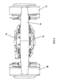
Figure 2 is a front view of the vehicle in a first, namely non inverted, position. -
Figure 3 is a top view of the first position with the first car housing on top. -
Figure 4 is a rear view of the first position. -
Figure 5 is a side view of the first position. -
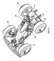
Figure 6 is a perspective view of the first position. -
Figure 7 is a perspective view of the first position. -
Figure 8 is a perspective view of the inverted position. -
Figure 9 is a perspective view of the inverted position. -
Figure 10 illustrates the toy showing the front bumper, 4 wheels, front and rear body as well as first car housing. -
Figure 11 illustrates the perspective view of the first position of the vehicle showing the charging plug and first car housing. -
Figure 12 illustrates the perspective view of inverted position, showing the charging plug and second car housing. -
Figure 13 shows representations of the remote controller, and electronic circuit in the vehicle with different components illustrated in block form. - Certain terminology is used in the following description for convenience only and is not limiting. The words "lower" and "upper" designate directions in the drawings to which reference is made. The words "inwardly" and "outwardly" refer to directions toward and away from, respectively, the geometric center of the vehicle and designated parts thereof. The word "a" is defined to mean "at least one." The terminology includes the words above specifically mentioned, derivatives thereof and words of similar import. In the drawings, like numerals are used to indicate like elements throughout.
- The toy car comprises of two separate car bodies. These two bodies are installed on the opposite side of a chassis. The wheel diameter is greater than the maximum height of car bodies. Therefore, when the car is inverted after crashing, flipping, jumping or playing stunt actions, the four wheels can still touch the ground surface. The car can be freely moved and controlled by users. However, once the car is inverted, the control method on transmitter is changed too.
- In prior systems, as the direction of wheel rotation does not change after car inversion, the forward and backward movement will be reversed. i.e. press the throttle trigger will drive the car backward and push the throttle trigger forward will drive the car forward. This is the reverse case of normal convention. Similarly, this situation also applies in left/right steering control. Thus, users will be very confused to control the car after inversion.
- This disclosure relates to a twin-body high speed remote control toy car, and system to avoid this confusion by a user, so that irrespective of the orientation of the car the user can control the car direction and speed with a minimum of difficulty.
- According to the disclosure a toy vehicle, such as a toy car comprises a vehicle body with a front portion and a rear portion and a longitudinal axis extending through the front and rear portions. There is at least one rear wheel coupled with the rear portion and located on the vehicle so as to at least partially support the rear portion.
- An electric steering motor is drivingly coupled with at least one wheel. There is at least one front wheel coupled with the front portion and located on the vehicle so as to at least partially support the front portion.
- An electrically operated steering actuator is mounted for drivingly coupling at least one wheel to rotate at least one wheel to steer the toy vehicle. A driving motor rotates at least one wheel.
- An orientation sensor determines whether the vehicle body is in a first upright position or a second inverse upside down position about the longitudinal axis.
- A toy vehicle comprising a movable vehicle and a remote control device having controls for a user to regulate the movement of the vehicle. The orientation sensor determines whether the vehicle body is in a first upright position or a second inverse upside down position about the longitudinal axis. The orientation sensor acts through a microprocessor to switch the direction of rotation of the driven wheels independently of a user changing the controls on the remote control device.
- There is an elastic linkage coupling the front and rear portions together, and wherein the at least one rear wheel is the driven wheel.
- The car preferably includes a pair of front wheels spaced apart to either side of the vehicle body, and a preferably a pair of rear wheels spaced apart to either side of the vehicle body. There is a pair of spaced elastic linkages arranged to either side of the longitudinal axis which is centrally located between the front and rear portions of the vehicle, and a pair of driving motors for driving the rear wheels.
- Further the body can include first and second body housings, the second body housing being the chassis for the first body housing, the first body housing being the chassis for the second body housing. The extremities of the first and second housings have a height between the extremities, and the wheels have diameter greater than the height.
- There is a remote control device for communicating with a transceiver located with the vehicle. The transceiver is connected with the orientation sensor, and can selectively signal the orientation of the vehicle to the remote control device.
- The remote control device includes one or more control levers also for regulating the rotation of the driven wheel. There can be a program for switching the direction of rotation of the driven wheel(s).
- As such the vehicle can be controlled on the one hand by the microprocessor to automatically switch the rotation and steering instructions to the wheels when the car flips is inverted. Additionally the controller can regulate the direction and steering as desired. Thus when the vehicle is orientated in a first direction the wheels rotate and are steered in a first direction, and when the vehicle is in the inverse direction the wheels rotate and are steered in a second direction.
- When the remote control receives a signal from the transceiver that the orientation has been inverted, the wheels are rotating in the opposite direction, thereby the remote control device can retain control of the vehicle without switching the orientation of a controller on the remote control device.
- When the vehicle is inverted, the sensor detects the orientation change and signals a microprocessor inside the vehicle, the microprocessor responds to the signal and changes the left/right motor control signal to the steering motor and the forward/backward motor control signal on the driving motor.
- The wheels are formed of low density material, such as a foam material.
- The toy is a combination with a remote control device configured to selectively control movement of the toy vehicle and activation of the rotational drive mechanism.
- The remote control device comprises a handheld remote controller having a multi-part housing, and wherein at least two of the housing parts are pivotable with respect to each other in order to control an operation of the toy vehicle.
- The twin-body toy car is based on the following design so as to achieve user-friendly control, good controllability and high speed.
- In order to obtain high speed, the car should be light, preferably no more than about 50g. There is a relatively powerful motor to drive at least one of the rear wheels, the wheels are made of sponge, the car body is made of light plastic material such as polypropylene or more high energy density LiPO batteries are chosen. There are miniature coreless motors used for driving the front and rear wheels as needed.
- As arranged, the second car housing is at least part of the chassis of the first car housing in first position. Similarly, the first car housing is at least part of the chassis of the second car housing in the inverted position.
- The control system is preferably a 2.4GHz frequency which is chosen because of the compact electronics and also built-in antenna on the PCB.
- There is a symmetric suspension system on the chassis to withstand the shock or force exerting on either car housings when the vehicle crashes, flips and/or jumps.
- There can be one or more sensors to detect orientation. The car is equipped with a vertical orientation sensor. Once the car is inverted, the sensor detects this change and sends a signal to a microprocessor in the control electronics inside the car. The microprocessor responds to this signal change and exchanges the left/right motor control signal on steering motor and forward/backward motor control signal on rear driving motor. As such the user does not exactly need to know which car body is on top. The user can simply keep the trigger and/or steering wheel position in order to maintain the same movement as before.
- The
toy car 10 comprises - 1. A
front body 12 which includes- (1)
First car housing 14 - (2)
Second car housing 16 - (3) A
steering mechanism 18 associated with asmall dc motor 20, potentiometer andgearbox 22 for precise servo control. - (4)
Front suspension system 24 for shock absorbing. - (5) A
front bumper 26 for shock absorbing. - (6) 2
sponge wheels - (7)
Battery power source 32 such as LiPO, LiFePO4 or Li-ion. - (8)
PCBA 34 for electronicmicroprocessor system control 36 and a radio transceiver 38 in 2.4GHz for 2-way communication. - (9) A
vertical orientation sensor 70 for inversion detection.
- (1)
- A
rear body 40 includes - (1) A driving mechanism associated with one or two powerful dc coreless motor(s) 42 and gearbox(es) 44.
- (2) A
rear suspension system 46 for shock absorbing - (3) 2
sponge wheels - There is a
radio controller 52 which is remotely located relative to thecar 10 and is used by the user to control speed and direction with different toggle controls 54, 56 and 58 on the face of the controller. There can be acharger unit 60 associated with thecontroller 52, and the charger is connectable through acable 62 for recharging thebattery 32. In an alternative way, thecharger unit 60 can be located inside thecar 10, the primary battery is connected to thecharger unit 60 through acable 62. - There are two mechanical
elastic linkages - The front chassis comprises a first top housing and a first bottom housing according to the respective vertical orientation of the care.
- The front body can have different forms and can include a hood and fenders mounted to the first top housing. The steering assembly is mounted with the front body, and the front supports a front bumper and at least one and preferably two front wheel assemblies. The front body can further include a first battery, and if desired a second battery.
- The front wheel assemblies each include a wheel hub and a tire. The hub is attached to a support arm. The support arms can include a top support pin and a bottom support pin. The support arms further include a steering pivot pin.
- The steering assembly is coupled to the wheel assemblies to provide powered steering control. The steering assembly is preferably a conventional design that includes a motor, a slip clutch and a steering gear box, all of which can be contained within motor and gear box housing. A steering actuating lever can extend from the motor and gear box housing, and moves from left to right. The steering actuating lever can fits within a receptacle in a tie rod. The tie rod is provided with holes at each opposing end. The steering pivot pins fit within the holes. As the tie rod moves left and right under the action of the steering actuating lever the front wheel assemblies are caused to turn as support arms are pivoted by steering pivot pins. The position of the tie rod can be adjustable by a steering trim mechanism. One of ordinary skill will appreciate that any know steering assembly can be used with the present disclosure to provide steering control of the
toy vehicle 10. - The rear chassis can include a second top housing and a second bottom housing.
- The housings can be ornamented cover assemblies.
- The rear chassis mounts a drive assembly, one or more rear wheel assemblies mounted to an axle, and mounted for rotation relative to the housing. The housing can include a drive shaft aft support member, a drive shaft forward support member, a spring support member.
- A circuit board containing the device electronics is supported by a mounting with the front body. The circuit board is electrically connected with the front and rear motors. An on/off switch is accessible from the underside of the bottom housing.
- The antenna is preferably coupled within or to circuit board and is capable of receiving and/or transmitting signals between a remote controller and the circuit board to control operation of the
toy vehicle 10. - The drive assembly includes one or two drive motors. The drive motors can be reversible electric motors of the type generally used in toy vehicles. The motors are operably coupled to the axle through a drive gear train. The
drive gear train 320 includes a pinion affixed to an output shaft of the drive motors. The pinion engages a combined reduction gear with other gears fixedly attached to theaxle 256. The motors can thus drive the rear wheel assemblies through the drive gear train in either a forward or reverse direction. Other drive train arrangements could be used such as belts or other forms of power transmission. The arrangements disclosed herein are not meant to be limiting. - In operation, a user drives the
toy vehicle 10 so that irrespective of the orientation the vehicle can continue driving in the selected forward or reverse direction. There is no need for the user to operate the toggle in an opposite direction if the vehicle happens to flip over and is oppositely orientated. The microprocessor on board is signaled by the orientation sensor and it acts to change the direction of rotation of the wheels when the vehicle is orientated oppositely to the normal chosen orientation. In other words the vehicle keeps travelling in the same direction of movement without corrective action of the user. Similarly the left /right steering controls are switched around independent of the user. - The
vehicle 10 can be constructed of, for example, plastic or any other suitable material such as metal or composite materials. From this disclosure, it would be obvious to one skilled in the art to vary the dimensions of thetoy vehicle 10 shown, for example making components of the toy vehicle smaller or larger relative to the other components. Thevehicle 10 may flip while in motion on the ground, or while in the air (e.g. while jumping off of a ramp). - The
toy vehicle 10 is preferably controlled via radio (wireless) signals from a remote controller. However, other types of controllers may be used including wired controllers, voice-activated controllers, and the like. - A preferred embodiment of a remote controller for use with the present disclosure preferably comprises a multi-part housing having left hand and right hand toggles. Each of the left hand and right hand toggles are on a top housing. An antenna may be included to receive and/or transmit signals to and/or from the remote controller.
- The remote controller also preferably includes circuitry to, for example, process inputs from the switch, the left and right toggles, switches, and to transmit and receive signals to and from the
toy vehicle 10. - It will be understood that the remote controller 500 can be formed of a variety materials and may be modified to include additional switches and/or buttons. It will be further understood that a variety of other types of controllers may be used to control the operation of the toy vehicle of the present disclosure.
- One of ordinary skill will appreciate that although the embodiments discussed above refer to a single orientation sensor, there could be more than one sensor with the
toy vehicle 10 and other modes of operation could be used depending on orientation. For example, the one or more sensors could be actuated upon driving the vehicle in a forward direction, or by activating a switch on a remote controller, or by having thetoy vehicle 10 pass over a beacon which is detected by circuitry on thetoy vehicle 10. Orientation, other than upright or upside down may be sensed, and the drive and steering motors operated appropriately according to a sensed orientation and programmed operation. - It will be appreciated by those skilled in the art that changes could be made to the embodiments described above without departing from the broad inventive concept thereof. It is understood, therefore, that this disclosure is not limited to the particular embodiments disclosed, but it is intended to cover modifications within the spirit and scope of the present disclosure.
- Many of the features of the present disclosure are implemented by suitable algorithms that are executed by one or more the microprocessors with the vehicle and/or remote controller. For example, all voltages and, currents at critical circuit points, and velocity are monitored by the software routines.
- Although the present disclosure has been described with respect to particular embodiments thereof, variations are possible. Although the disclosure is described of a four-wheeled embodiment, the present disclosure there could also comprise a vehicle having three wheels, or more than four wheels or a track drive system. There may be a motorcycle format with 2 wheels, or a system with 3 wheels, for instance two in the rear and one in the front. The microprocessor for changing direction and turning of the wheels may be located in the remote controller device rather than the vehicle.
- The present disclosure may be embodied in specific forms without departing from the essential spirit or attributes thereof. In particular, although the disclosure is illustrated using a particularly format with particular component values, one skilled in the art will recognize that various values and schematics will fall within the scope of the disclosure. It is desired that the embodiments described herein be considered in all respects illustrative and not restrictive and that reference be made to the appended claims and their equivalents for determining the scope of the disclosure.
Claims (9)
- A toy vehicle (10) comprising a movable vehicle and a remote control device (52) having controls for a user to regulate the movement of the vehicle, the vehicle having a vehicle body with a front portion (12) and a rear portion (40) and a longitudinal axis extending through the front and rear portions; at least one rear wheel (48; 50) coupled with the rear portion and located on the vehicle so as to at least partially support the rear portion; an electric steering motor (20) drivingly coupled with at least one wheel; at least one front wheel (28; 30) coupled with the front portion and located on the vehicle so as to at least partially support the front portion; an electrically operated steering actuator (22) mounted for drivingly coupling at least one wheel (28; 30) to rotate at least one wheel to steer the toy vehicle (10); a driving motor (42) for rotating at least one wheel;
characterized in that it further comprises an orientation sensor (70) for determining whether the vehicle body is in a first upright position or a second inverse upside down position about the longitudinal axis, the orientation sensor acting through a microprocessor (36) to switch the direction of rotation of the driven wheels independently of a user changing the controls on the remote control device (52). - The toy vehicle (10) according to claim 1, characterized in that the orientation sensor (70) acts through said microprocessor (36) to switch the steering control of the steered wheel from a left to right steering or a right to left steering according to the orientation of the vehicle independently of a user changing the controls on the remote control device (52), and thereby retaining the vehicle travelling in the same direction without intervening action by the user.
- The toy vehicle (10) according to claim 1, characterized in that when the vehicle is inverted, the sensor (70) detects the orientation change and signals said microprocessor (36) inside the vehicle, said microprocessor responds to the signal and changes the left/right motor control signal to the steering motor and the forward/backward motor control signal on the driving motor (42).
- The toy vehicle (10) according to claim 1, characterized in that it further includes an elastic linkage (64) coupling the front and rear portions together, and in that the at least one rear wheel (48; 50) is the driven wheel.
- The toy vehicle (10) according to claim 2, characterized in that it further includes a pair of front wheels (28; 30) spaced apart to either side of the vehicle body, a pair of rear wheels (48; 50) spaced apart to either side of the vehicle body, a pair of spaced elastic linkages (64) arranged to either side of the longitudinal axis which is centrally located between the front and rear portions of the vehicle, and a pair of driving motors (42) for driving the rear wheels.
- The toy vehicle (10) according to claim 3, characterized in that the body includes first (14) and second (16) body housings , the second body housing being the chassis for the first body housing, the first body housing being the chassis for the second body housing, the extremities of the first and second housings having a height between the extremities, and wherein the wheels have diameter greater than the height.
- The toy vehicle (10) according to claim 1, characterized in that if further includes said remote control device (52) for communicating with a transceiver (38) located with the vehicle, the transceiver being connected with the orientation sensor (70), and being for signaling the orientation of the vehicle to the remote control device (52), and in that the remote control device includes a control lever for regulating the rotation of the driven wheel, and including a program for switching the direction of rotation of the driven wheel relatively such when the vehicle is orientated in a first direction the wheels rotate in a first direction.
- The toy vehicle (10) according to claim 7, characterized in that when the remote control (52) receives a signal from the transceiver (38) that the orientation has been inverted, the wheels are rotating in the opposite direction, thereby the remote control device can retain control of the vehicle without switching the orientation of a controllers on the remote control device (52).
- The toy vehicle (10) according to claim 1, characterized in that the wheels (28, 30, 48, 50) are formed of low density material.
Applications Claiming Priority (1)
| Application Number | Priority Date | Filing Date | Title |
|---|---|---|---|
| US12/965,696 US8038504B1 (en) | 2010-12-10 | 2010-12-10 | Toy vehicle |
Publications (2)
| Publication Number | Publication Date |
|---|---|
| EP2463002A1 EP2463002A1 (en) | 2012-06-13 |
| EP2463002B1 true EP2463002B1 (en) | 2013-08-07 |
Family
ID=44773293
Family Applications (1)
| Application Number | Title | Priority Date | Filing Date |
|---|---|---|---|
| EP11166343.1A Not-in-force EP2463002B1 (en) | 2010-12-10 | 2011-05-17 | Toy vehicle |
Country Status (3)
| Country | Link |
|---|---|
| US (1) | US8038504B1 (en) |
| EP (1) | EP2463002B1 (en) |
| HK (1) | HK1166620A1 (en) |
Cited By (1)
| Publication number | Priority date | Publication date | Assignee | Title |
|---|---|---|---|---|
| CN104524781A (en) * | 2014-12-12 | 2015-04-22 | 广东银润实业有限公司 | Intelligent jumping toy car and preparation method thereof |
Families Citing this family (32)
| Publication number | Priority date | Publication date | Assignee | Title |
|---|---|---|---|---|
| WO2012012889A1 (en) * | 2010-07-30 | 2012-02-02 | Thinking Technology, Inc. | Two-sided toy vehicle |
| US10281915B2 (en) | 2011-01-05 | 2019-05-07 | Sphero, Inc. | Multi-purposed self-propelled device |
| US9218316B2 (en) | 2011-01-05 | 2015-12-22 | Sphero, Inc. | Remotely controlling a self-propelled device in a virtualized environment |
| US8751063B2 (en) | 2011-01-05 | 2014-06-10 | Orbotix, Inc. | Orienting a user interface of a controller for operating a self-propelled device |
| US9090214B2 (en) | 2011-01-05 | 2015-07-28 | Orbotix, Inc. | Magnetically coupled accessory for a self-propelled device |
| US9429940B2 (en) * | 2011-01-05 | 2016-08-30 | Sphero, Inc. | Self propelled device with magnetic coupling |
| US20120244969A1 (en) | 2011-03-25 | 2012-09-27 | May Patents Ltd. | System and Method for a Motion Sensing Device |
| US8894465B2 (en) * | 2011-04-28 | 2014-11-25 | Kids Ii, Inc. | Eccentric motion toy |
| US8807619B2 (en) * | 2011-08-29 | 2014-08-19 | Michael Ray Miller | Remote controlled rescue vehicle |
| US9292758B2 (en) | 2012-05-14 | 2016-03-22 | Sphero, Inc. | Augmentation of elements in data content |
| KR20150012274A (en) | 2012-05-14 | 2015-02-03 | 오보틱스, 아이엔씨. | Operating a computing device by detecting rounded objects in image |
| US9827487B2 (en) | 2012-05-14 | 2017-11-28 | Sphero, Inc. | Interactive augmented reality using a self-propelled device |
| US10105616B2 (en) * | 2012-05-25 | 2018-10-23 | Mattel, Inc. | IR dongle with speaker for electronic device |
| US10056791B2 (en) | 2012-07-13 | 2018-08-21 | Sphero, Inc. | Self-optimizing power transfer |
| US9427672B2 (en) | 2013-02-07 | 2016-08-30 | Objex Design | Stunt arenas for remote control vehicles |
| US9829882B2 (en) | 2013-12-20 | 2017-11-28 | Sphero, Inc. | Self-propelled device with center of mass drive system |
| CN104248846B (en) * | 2014-09-30 | 2017-04-05 | 广东奥飞动漫文化股份有限公司 | A kind of two-sided toy car that can vertically turn round in closed orbit |
| DE112015005062T5 (en) * | 2014-11-07 | 2017-07-20 | Traxxas Lp | Self-erecting model vehicle |
| CN106390472B (en) * | 2016-09-06 | 2019-03-05 | 东莞美驰图实业有限公司 | A kind of electric vehicle |
| CN108096847A (en) * | 2016-11-24 | 2018-06-01 | 苍安国 | Electric toy car |
| CN106621361B (en) * | 2017-02-24 | 2022-11-04 | 深圳市比赛得科技有限公司 | Pattern playing method remote control car |
| CN107042019B (en) * | 2017-02-24 | 2022-11-25 | 深圳市比赛得科技有限公司 | Remote control car and car tail height adjusting device thereof |
| USD825684S1 (en) * | 2017-06-07 | 2018-08-14 | MerchSource, LLC | Remote control car |
| USD842388S1 (en) * | 2017-10-16 | 2019-03-05 | Shenzhen Qianhai Value Online Ecommerce Co., Ltd. | Toy vehicle |
| US20190324447A1 (en) * | 2018-04-24 | 2019-10-24 | Kevin Michael Ryan | Intuitive Controller Device for UAV |
| CN109949562A (en) * | 2019-04-01 | 2019-06-28 | 江门宇度科技有限责任公司 | A kind of controller applied to intelligent electric perambulator |
| USD947289S1 (en) * | 2019-08-14 | 2022-03-29 | Peiyi Lin | Toy car |
| US11135523B2 (en) | 2019-12-20 | 2021-10-05 | Spin Master Ltd. | Toy vehicle with selected centre of gravity |
| USD952050S1 (en) * | 2019-12-30 | 2022-05-17 | Spin Master, Ltd. | Toy vehicle |
| USD923110S1 (en) * | 2019-12-30 | 2021-06-22 | Spin Master Ltd. | Toy vehicle |
| CN215436744U (en) * | 2021-08-07 | 2022-01-07 | 嘉兴市金潼电子股份有限公司 | Children drift car |
| US20230118786A1 (en) * | 2021-10-19 | 2023-04-20 | Silverlit Limited | Toy vehicle suspension and wheels |
Family Cites Families (36)
| Publication number | Priority date | Publication date | Assignee | Title |
|---|---|---|---|---|
| US1871297A (en) | 1930-06-28 | 1932-08-09 | Samuel I Berger | Toy tank |
| US1868313A (en) | 1931-01-29 | 1932-07-19 | Daubendiek Armin | Toy |
| US2064309A (en) | 1936-02-14 | 1936-12-15 | Marx & Co Louis | Toy vehicle |
| US2247354A (en) | 1937-10-13 | 1941-07-01 | Unique Art Mfg Co Inc | Toy |
| US2794295A (en) | 1956-03-23 | 1957-06-04 | Theodore A Robertson | Wheeled tumbling toy |
| US3445959A (en) * | 1967-01-25 | 1969-05-27 | Marvin Glass & Associates | Reversible race car |
| US4209942A (en) | 1978-05-30 | 1980-07-01 | Lohr Raymond J | Remote control car |
| JPS5942063Y2 (en) * | 1979-06-15 | 1984-12-06 | 株式会社トミー | inverted running toy |
| JPS5953098U (en) | 1982-09-30 | 1984-04-07 | 株式会社タカラ | traveling toy |
| US4655724A (en) | 1985-12-27 | 1987-04-07 | Soma International Ltd. | Toy vehicle and steering and drive mechanism therefor |
| GB2214099A (en) * | 1988-01-14 | 1989-08-31 | Synergistics Research Limited | A toy vehicle |
| US4969851A (en) * | 1990-01-26 | 1990-11-13 | Marvin Glass & Associates Liquidating Trust | Toy vehicle with changing style feature |
| US6837327B2 (en) | 1993-02-24 | 2005-01-04 | Deka Products Limited Partnership | Controlled balancing toy |
| US5667420A (en) * | 1994-01-25 | 1997-09-16 | Tyco Industries, Inc. | Rotating vehicle toy |
| US5727985A (en) | 1994-05-24 | 1998-03-17 | Tonka Corporation | Stunt performing toy vehicle |
| US5868600A (en) | 1997-04-21 | 1999-02-09 | Asahi Corporation | Toy car |
| US6439948B1 (en) * | 1997-08-19 | 2002-08-27 | Mattel, Inc. | Two-wheeled amphibious toy vehicle |
| US5921843A (en) | 1997-12-04 | 1999-07-13 | Hasbro, Inc. | Remote controlled toy vehicle |
| US6234866B1 (en) * | 1998-12-11 | 2001-05-22 | Eliyahu Ben-Yakar | Toy vehicle |
| US6589098B2 (en) | 1999-08-06 | 2003-07-08 | Mattel, Inc. | Toy vehicle with pivotally mounted side wheels |
| US6458008B1 (en) | 2000-09-05 | 2002-10-01 | Jamie Hyneman | Remote control device with gyroscopic stabilization and directional control |
| US6705917B2 (en) | 2000-12-15 | 2004-03-16 | Andrew S. Filo | Self-phase synchronized walking and turning quadruped apparatus |
| US6764374B2 (en) | 2001-03-23 | 2004-07-20 | Leynian Ltd. Co. | Toy vehicle with multiple gyroscopic action wheels |
| US6692333B2 (en) | 2002-05-31 | 2004-02-17 | The Obb, Llc | Toy vehicle |
| FR2840540A1 (en) * | 2002-06-11 | 2003-12-12 | Janick Simeray | Motorized mobile toy for children, has two sensors that deliver control signals, where signal difference controls steering of toy and signals sum controls driving forward of toy so that toy follows and reaches spot on ground |
| US7032980B2 (en) * | 2002-06-27 | 2006-04-25 | The Little Tikes Company | Non-slip wheel for a child's toy |
| US6746304B1 (en) | 2003-04-14 | 2004-06-08 | Shu-Ming Liu | Remote-control toy car set |
| US7056185B1 (en) | 2004-10-04 | 2006-06-06 | Thomas Anagnostou | Single axle wireless remote controlled rover with omnidirectional wheels |
| CN101072611A (en) * | 2004-10-26 | 2007-11-14 | 美泰有限公司 | Toy vehicle with big wheel |
| US7980916B2 (en) | 2004-12-30 | 2011-07-19 | Clark Jr Leonard R | Wall racer toy vehicles |
| US6939197B1 (en) | 2005-02-03 | 2005-09-06 | Bang Zoom Design Ltd. | Toy vehicle with enhanced jumping capability |
| WO2006113687A2 (en) | 2005-04-20 | 2006-10-26 | Robotic Amusements, Llc | Game with remotely controlled game vehicles |
| DE602006021053D1 (en) | 2005-11-04 | 2011-05-12 | Mattel Inc | TOY VEHICLE |
| MX2008014107A (en) | 2006-05-04 | 2008-11-14 | Mattel Inc | Transformable toy vehicle. |
| US20090149113A1 (en) | 2007-12-06 | 2009-06-11 | Lund And Company Invention, L.L.C. | Rolling and Flipping Vehicle |
| US20110031044A1 (en) * | 2009-08-04 | 2011-02-10 | Ehud Gal | Robotic platform & methods for overcoming obstacles |
-
2010
- 2010-12-10 US US12/965,696 patent/US8038504B1/en not_active Expired - Fee Related
-
2011
- 2011-05-17 EP EP11166343.1A patent/EP2463002B1/en not_active Not-in-force
-
2012
- 2012-07-25 HK HK12107336.4A patent/HK1166620A1/en not_active IP Right Cessation
Cited By (1)
| Publication number | Priority date | Publication date | Assignee | Title |
|---|---|---|---|---|
| CN104524781A (en) * | 2014-12-12 | 2015-04-22 | 广东银润实业有限公司 | Intelligent jumping toy car and preparation method thereof |
Also Published As
| Publication number | Publication date |
|---|---|
| EP2463002A1 (en) | 2012-06-13 |
| US8038504B1 (en) | 2011-10-18 |
| HK1166620A1 (en) | 2012-12-28 |
Similar Documents
| Publication | Publication Date | Title |
|---|---|---|
| EP2463002B1 (en) | Toy vehicle | |
| US6939197B1 (en) | Toy vehicle with enhanced jumping capability | |
| US9931580B2 (en) | Toy vehicle with rollover stunt movements | |
| US7662017B2 (en) | Toy vehicle | |
| US4541814A (en) | Radio controlled vehicle within a sphere | |
| US7344430B2 (en) | Remote/occupant controlled toy vehicle | |
| EP1251916B1 (en) | Remotely controlled skateboard having motion-responsive doll riding thereon | |
| CN1234437C (en) | Three-wheeled wireless controlld toy stunt vehicle | |
| US8162715B2 (en) | Remote-controlled toy vehicle | |
| EP1230963A3 (en) | Remotely-controlled toy skateboard device | |
| US4695266A (en) | Steerable electric toy car | |
| EP1954365B1 (en) | Toy vehicle | |
| EP2865429B1 (en) | Smart driving system in toy vehicle | |
| US8562387B1 (en) | Driving mechanism for remote control toy vehicle | |
| US20230118786A1 (en) | Toy vehicle suspension and wheels | |
| US20130072085A1 (en) | Toy vehicle | |
| EP2594324B1 (en) | Steering mechanism for toy vehicle | |
| US20030082992A1 (en) | Trim adjustment feature for toy vehicles | |
| GB2328621A (en) | Toy vehicle | |
| JP3330367B2 (en) | Remote-controlled traveling toys | |
| CN211410983U (en) | Toy dump truck | |
| CN211435079U (en) | Toy drift car | |
| CN211245515U (en) | Double round toy remote control tip lorry | |
| WO2018158833A1 (en) | Traveling body | |
| CN110801635A (en) | Toy drift car |
Legal Events
| Date | Code | Title | Description |
|---|---|---|---|
| PUAI | Public reference made under article 153(3) epc to a published international application that has entered the european phase |
Free format text: ORIGINAL CODE: 0009012 |
|
| AK | Designated contracting states |
Kind code of ref document: A1 Designated state(s): AL AT BE BG CH CY CZ DE DK EE ES FI FR GB GR HR HU IE IS IT LI LT LU LV MC MK MT NL NO PL PT RO RS SE SI SK SM TR |
|
| AX | Request for extension of the european patent |
Extension state: BA ME |
|
| REG | Reference to a national code |
Ref country code: HK Ref legal event code: DE Ref document number: 1166620 Country of ref document: HK |
|
| 17P | Request for examination filed |
Effective date: 20121130 |
|
| GRAP | Despatch of communication of intention to grant a patent |
Free format text: ORIGINAL CODE: EPIDOSNIGR1 |
|
| RIC1 | Information provided on ipc code assigned before grant |
Ipc: A63H 30/04 20060101ALI20130125BHEP Ipc: A63H 17/00 20060101AFI20130125BHEP |
|
| GRAS | Grant fee paid |
Free format text: ORIGINAL CODE: EPIDOSNIGR3 |
|
| GRAA | (expected) grant |
Free format text: ORIGINAL CODE: 0009210 |
|
| AK | Designated contracting states |
Kind code of ref document: B1 Designated state(s): AL AT BE BG CH CY CZ DE DK EE ES FI FR GB GR HR HU IE IS IT LI LT LU LV MC MK MT NL NO PL PT RO RS SE SI SK SM TR |
|
| REG | Reference to a national code |
Ref country code: GB Ref legal event code: FG4D |
|
| REG | Reference to a national code |
Ref country code: AT Ref legal event code: REF Ref document number: 625491 Country of ref document: AT Kind code of ref document: T Effective date: 20130815 Ref country code: CH Ref legal event code: EP |
|
| REG | Reference to a national code |
Ref country code: DE Ref legal event code: R082 Ref document number: 602011002580 Country of ref document: DE Representative=s name: PATENTANWALTSKANZLEI MEYER, DE |
|
| REG | Reference to a national code |
Ref country code: IE Ref legal event code: FG4D |
|
| REG | Reference to a national code |
Ref country code: DE Ref legal event code: R096 Ref document number: 602011002580 Country of ref document: DE Effective date: 20131002 |
|
| REG | Reference to a national code |
Ref country code: HK Ref legal event code: GR Ref document number: 1166620 Country of ref document: HK |
|
| REG | Reference to a national code |
Ref country code: AT Ref legal event code: MK05 Ref document number: 625491 Country of ref document: AT Kind code of ref document: T Effective date: 20130807 |
|
| REG | Reference to a national code |
Ref country code: NL Ref legal event code: VDEP Effective date: 20130807 |
|
| REG | Reference to a national code |
Ref country code: LT Ref legal event code: MG4D |
|
| PG25 | Lapsed in a contracting state [announced via postgrant information from national office to epo] |
Ref country code: PT Free format text: LAPSE BECAUSE OF FAILURE TO SUBMIT A TRANSLATION OF THE DESCRIPTION OR TO PAY THE FEE WITHIN THE PRESCRIBED TIME-LIMIT Effective date: 20131209 Ref country code: SE Free format text: LAPSE BECAUSE OF FAILURE TO SUBMIT A TRANSLATION OF THE DESCRIPTION OR TO PAY THE FEE WITHIN THE PRESCRIBED TIME-LIMIT Effective date: 20130807 Ref country code: AT Free format text: LAPSE BECAUSE OF FAILURE TO SUBMIT A TRANSLATION OF THE DESCRIPTION OR TO PAY THE FEE WITHIN THE PRESCRIBED TIME-LIMIT Effective date: 20130807 Ref country code: IS Free format text: LAPSE BECAUSE OF FAILURE TO SUBMIT A TRANSLATION OF THE DESCRIPTION OR TO PAY THE FEE WITHIN THE PRESCRIBED TIME-LIMIT Effective date: 20131207 Ref country code: NO Free format text: LAPSE BECAUSE OF FAILURE TO SUBMIT A TRANSLATION OF THE DESCRIPTION OR TO PAY THE FEE WITHIN THE PRESCRIBED TIME-LIMIT Effective date: 20131107 Ref country code: CY Free format text: LAPSE BECAUSE OF FAILURE TO SUBMIT A TRANSLATION OF THE DESCRIPTION OR TO PAY THE FEE WITHIN THE PRESCRIBED TIME-LIMIT Effective date: 20130828 Ref country code: LT Free format text: LAPSE BECAUSE OF FAILURE TO SUBMIT A TRANSLATION OF THE DESCRIPTION OR TO PAY THE FEE WITHIN THE PRESCRIBED TIME-LIMIT Effective date: 20130807 Ref country code: HR Free format text: LAPSE BECAUSE OF FAILURE TO SUBMIT A TRANSLATION OF THE DESCRIPTION OR TO PAY THE FEE WITHIN THE PRESCRIBED TIME-LIMIT Effective date: 20130807 |
|
| PG25 | Lapsed in a contracting state [announced via postgrant information from national office to epo] |
Ref country code: PL Free format text: LAPSE BECAUSE OF FAILURE TO SUBMIT A TRANSLATION OF THE DESCRIPTION OR TO PAY THE FEE WITHIN THE PRESCRIBED TIME-LIMIT Effective date: 20130807 Ref country code: LV Free format text: LAPSE BECAUSE OF FAILURE TO SUBMIT A TRANSLATION OF THE DESCRIPTION OR TO PAY THE FEE WITHIN THE PRESCRIBED TIME-LIMIT Effective date: 20130807 Ref country code: GR Free format text: LAPSE BECAUSE OF FAILURE TO SUBMIT A TRANSLATION OF THE DESCRIPTION OR TO PAY THE FEE WITHIN THE PRESCRIBED TIME-LIMIT Effective date: 20131108 Ref country code: FI Free format text: LAPSE BECAUSE OF FAILURE TO SUBMIT A TRANSLATION OF THE DESCRIPTION OR TO PAY THE FEE WITHIN THE PRESCRIBED TIME-LIMIT Effective date: 20130807 Ref country code: SI Free format text: LAPSE BECAUSE OF FAILURE TO SUBMIT A TRANSLATION OF THE DESCRIPTION OR TO PAY THE FEE WITHIN THE PRESCRIBED TIME-LIMIT Effective date: 20130807 Ref country code: BE Free format text: LAPSE BECAUSE OF FAILURE TO SUBMIT A TRANSLATION OF THE DESCRIPTION OR TO PAY THE FEE WITHIN THE PRESCRIBED TIME-LIMIT Effective date: 20130807 Ref country code: NL Free format text: LAPSE BECAUSE OF FAILURE TO SUBMIT A TRANSLATION OF THE DESCRIPTION OR TO PAY THE FEE WITHIN THE PRESCRIBED TIME-LIMIT Effective date: 20130807 |
|
| PG25 | Lapsed in a contracting state [announced via postgrant information from national office to epo] |
Ref country code: CY Free format text: LAPSE BECAUSE OF FAILURE TO SUBMIT A TRANSLATION OF THE DESCRIPTION OR TO PAY THE FEE WITHIN THE PRESCRIBED TIME-LIMIT Effective date: 20130807 |
|
| PG25 | Lapsed in a contracting state [announced via postgrant information from national office to epo] |
Ref country code: CZ Free format text: LAPSE BECAUSE OF FAILURE TO SUBMIT A TRANSLATION OF THE DESCRIPTION OR TO PAY THE FEE WITHIN THE PRESCRIBED TIME-LIMIT Effective date: 20130807 Ref country code: EE Free format text: LAPSE BECAUSE OF FAILURE TO SUBMIT A TRANSLATION OF THE DESCRIPTION OR TO PAY THE FEE WITHIN THE PRESCRIBED TIME-LIMIT Effective date: 20130807 Ref country code: SK Free format text: LAPSE BECAUSE OF FAILURE TO SUBMIT A TRANSLATION OF THE DESCRIPTION OR TO PAY THE FEE WITHIN THE PRESCRIBED TIME-LIMIT Effective date: 20130807 Ref country code: DK Free format text: LAPSE BECAUSE OF FAILURE TO SUBMIT A TRANSLATION OF THE DESCRIPTION OR TO PAY THE FEE WITHIN THE PRESCRIBED TIME-LIMIT Effective date: 20130807 Ref country code: RO Free format text: LAPSE BECAUSE OF FAILURE TO SUBMIT A TRANSLATION OF THE DESCRIPTION OR TO PAY THE FEE WITHIN THE PRESCRIBED TIME-LIMIT Effective date: 20130807 |
|
| PG25 | Lapsed in a contracting state [announced via postgrant information from national office to epo] |
Ref country code: IT Free format text: LAPSE BECAUSE OF FAILURE TO SUBMIT A TRANSLATION OF THE DESCRIPTION OR TO PAY THE FEE WITHIN THE PRESCRIBED TIME-LIMIT Effective date: 20130807 Ref country code: ES Free format text: LAPSE BECAUSE OF FAILURE TO SUBMIT A TRANSLATION OF THE DESCRIPTION OR TO PAY THE FEE WITHIN THE PRESCRIBED TIME-LIMIT Effective date: 20130807 |
|
| PLBE | No opposition filed within time limit |
Free format text: ORIGINAL CODE: 0009261 |
|
| STAA | Information on the status of an ep patent application or granted ep patent |
Free format text: STATUS: NO OPPOSITION FILED WITHIN TIME LIMIT |
|
| 26N | No opposition filed |
Effective date: 20140508 |
|
| REG | Reference to a national code |
Ref country code: DE Ref legal event code: R097 Ref document number: 602011002580 Country of ref document: DE Effective date: 20140508 |
|
| PG25 | Lapsed in a contracting state [announced via postgrant information from national office to epo] |
Ref country code: LU Free format text: LAPSE BECAUSE OF FAILURE TO SUBMIT A TRANSLATION OF THE DESCRIPTION OR TO PAY THE FEE WITHIN THE PRESCRIBED TIME-LIMIT Effective date: 20140517 |
|
| REG | Reference to a national code |
Ref country code: CH Ref legal event code: PL |
|
| PG25 | Lapsed in a contracting state [announced via postgrant information from national office to epo] |
Ref country code: CH Free format text: LAPSE BECAUSE OF NON-PAYMENT OF DUE FEES Effective date: 20140531 Ref country code: MC Free format text: LAPSE BECAUSE OF FAILURE TO SUBMIT A TRANSLATION OF THE DESCRIPTION OR TO PAY THE FEE WITHIN THE PRESCRIBED TIME-LIMIT Effective date: 20130807 Ref country code: LI Free format text: LAPSE BECAUSE OF NON-PAYMENT OF DUE FEES Effective date: 20140531 |
|
| REG | Reference to a national code |
Ref country code: IE Ref legal event code: MM4A |
|
| PG25 | Lapsed in a contracting state [announced via postgrant information from national office to epo] |
Ref country code: IE Free format text: LAPSE BECAUSE OF NON-PAYMENT OF DUE FEES Effective date: 20140517 |
|
| PG25 | Lapsed in a contracting state [announced via postgrant information from national office to epo] |
Ref country code: MT Free format text: LAPSE BECAUSE OF FAILURE TO SUBMIT A TRANSLATION OF THE DESCRIPTION OR TO PAY THE FEE WITHIN THE PRESCRIBED TIME-LIMIT Effective date: 20130807 |
|
| REG | Reference to a national code |
Ref country code: FR Ref legal event code: PLFP Year of fee payment: 6 |
|
| PG25 | Lapsed in a contracting state [announced via postgrant information from national office to epo] |
Ref country code: SM Free format text: LAPSE BECAUSE OF FAILURE TO SUBMIT A TRANSLATION OF THE DESCRIPTION OR TO PAY THE FEE WITHIN THE PRESCRIBED TIME-LIMIT Effective date: 20130807 |
|
| PG25 | Lapsed in a contracting state [announced via postgrant information from national office to epo] |
Ref country code: BG Free format text: LAPSE BECAUSE OF FAILURE TO SUBMIT A TRANSLATION OF THE DESCRIPTION OR TO PAY THE FEE WITHIN THE PRESCRIBED TIME-LIMIT Effective date: 20130807 Ref country code: RS Free format text: LAPSE BECAUSE OF FAILURE TO SUBMIT A TRANSLATION OF THE DESCRIPTION OR TO PAY THE FEE WITHIN THE PRESCRIBED TIME-LIMIT Effective date: 20130807 |
|
| PG25 | Lapsed in a contracting state [announced via postgrant information from national office to epo] |
Ref country code: HU Free format text: LAPSE BECAUSE OF FAILURE TO SUBMIT A TRANSLATION OF THE DESCRIPTION OR TO PAY THE FEE WITHIN THE PRESCRIBED TIME-LIMIT; INVALID AB INITIO Effective date: 20110517 Ref country code: TR Free format text: LAPSE BECAUSE OF FAILURE TO SUBMIT A TRANSLATION OF THE DESCRIPTION OR TO PAY THE FEE WITHIN THE PRESCRIBED TIME-LIMIT Effective date: 20130807 |
|
| REG | Reference to a national code |
Ref country code: FR Ref legal event code: PLFP Year of fee payment: 7 |
|
| REG | Reference to a national code |
Ref country code: FR Ref legal event code: PLFP Year of fee payment: 8 |
|
| PG25 | Lapsed in a contracting state [announced via postgrant information from national office to epo] |
Ref country code: MK Free format text: LAPSE BECAUSE OF FAILURE TO SUBMIT A TRANSLATION OF THE DESCRIPTION OR TO PAY THE FEE WITHIN THE PRESCRIBED TIME-LIMIT Effective date: 20130807 |
|
| PG25 | Lapsed in a contracting state [announced via postgrant information from national office to epo] |
Ref country code: AL Free format text: LAPSE BECAUSE OF FAILURE TO SUBMIT A TRANSLATION OF THE DESCRIPTION OR TO PAY THE FEE WITHIN THE PRESCRIBED TIME-LIMIT Effective date: 20130807 |
|
| PGFP | Annual fee paid to national office [announced via postgrant information from national office to epo] |
Ref country code: DE Payment date: 20190508 Year of fee payment: 9 |
|
| PGFP | Annual fee paid to national office [announced via postgrant information from national office to epo] |
Ref country code: FR Payment date: 20190410 Year of fee payment: 9 |
|
| PGFP | Annual fee paid to national office [announced via postgrant information from national office to epo] |
Ref country code: GB Payment date: 20190417 Year of fee payment: 9 |
|
| REG | Reference to a national code |
Ref country code: DE Ref legal event code: R119 Ref document number: 602011002580 Country of ref document: DE |
|
| GBPC | Gb: european patent ceased through non-payment of renewal fee |
Effective date: 20200517 |
|
| PG25 | Lapsed in a contracting state [announced via postgrant information from national office to epo] |
Ref country code: GB Free format text: LAPSE BECAUSE OF NON-PAYMENT OF DUE FEES Effective date: 20200517 Ref country code: FR Free format text: LAPSE BECAUSE OF NON-PAYMENT OF DUE FEES Effective date: 20200531 |
|
| PG25 | Lapsed in a contracting state [announced via postgrant information from national office to epo] |
Ref country code: DE Free format text: LAPSE BECAUSE OF NON-PAYMENT OF DUE FEES Effective date: 20201201 |