EP2462872A1 - Providing additional information corresponding to change of blood flow with a time in ultrasound system - Google Patents
Providing additional information corresponding to change of blood flow with a time in ultrasound system Download PDFInfo
- Publication number
- EP2462872A1 EP2462872A1 EP11191707A EP11191707A EP2462872A1 EP 2462872 A1 EP2462872 A1 EP 2462872A1 EP 11191707 A EP11191707 A EP 11191707A EP 11191707 A EP11191707 A EP 11191707A EP 2462872 A1 EP2462872 A1 EP 2462872A1
- Authority
- EP
- European Patent Office
- Prior art keywords
- blood flow
- information
- color
- flow velocity
- ultrasound
- Prior art date
- Legal status (The legal status is an assumption and is not a legal conclusion. Google has not performed a legal analysis and makes no representation as to the accuracy of the status listed.)
- Granted
Links
Images



Classifications
-
- A—HUMAN NECESSITIES
- A61—MEDICAL OR VETERINARY SCIENCE; HYGIENE
- A61B—DIAGNOSIS; SURGERY; IDENTIFICATION
- A61B8/00—Diagnosis using ultrasonic, sonic or infrasonic waves
- A61B8/06—Measuring blood flow
-
- A—HUMAN NECESSITIES
- A61—MEDICAL OR VETERINARY SCIENCE; HYGIENE
- A61B—DIAGNOSIS; SURGERY; IDENTIFICATION
- A61B8/00—Diagnosis using ultrasonic, sonic or infrasonic waves
- A61B8/08—Clinical applications
-
- A—HUMAN NECESSITIES
- A61—MEDICAL OR VETERINARY SCIENCE; HYGIENE
- A61B—DIAGNOSIS; SURGERY; IDENTIFICATION
- A61B8/00—Diagnosis using ultrasonic, sonic or infrasonic waves
- A61B8/13—Tomography
-
- A—HUMAN NECESSITIES
- A61—MEDICAL OR VETERINARY SCIENCE; HYGIENE
- A61B—DIAGNOSIS; SURGERY; IDENTIFICATION
- A61B8/00—Diagnosis using ultrasonic, sonic or infrasonic waves
- A61B8/46—Ultrasonic, sonic or infrasonic diagnostic devices with special arrangements for interfacing with the operator or the patient
- A61B8/467—Ultrasonic, sonic or infrasonic diagnostic devices with special arrangements for interfacing with the operator or the patient characterised by special input means
- A61B8/469—Ultrasonic, sonic or infrasonic diagnostic devices with special arrangements for interfacing with the operator or the patient characterised by special input means for selection of a region of interest
-
- A—HUMAN NECESSITIES
- A61—MEDICAL OR VETERINARY SCIENCE; HYGIENE
- A61B—DIAGNOSIS; SURGERY; IDENTIFICATION
- A61B8/00—Diagnosis using ultrasonic, sonic or infrasonic waves
- A61B8/48—Diagnostic techniques
- A61B8/488—Diagnostic techniques involving Doppler signals
-
- A—HUMAN NECESSITIES
- A61—MEDICAL OR VETERINARY SCIENCE; HYGIENE
- A61B—DIAGNOSIS; SURGERY; IDENTIFICATION
- A61B8/00—Diagnosis using ultrasonic, sonic or infrasonic waves
- A61B8/52—Devices using data or image processing specially adapted for diagnosis using ultrasonic, sonic or infrasonic waves
- A61B8/5215—Devices using data or image processing specially adapted for diagnosis using ultrasonic, sonic or infrasonic waves involving processing of medical diagnostic data
- A61B8/5238—Devices using data or image processing specially adapted for diagnosis using ultrasonic, sonic or infrasonic waves involving processing of medical diagnostic data for combining image data of patient, e.g. merging several images from different acquisition modes into one image
-
- A—HUMAN NECESSITIES
- A61—MEDICAL OR VETERINARY SCIENCE; HYGIENE
- A61B—DIAGNOSIS; SURGERY; IDENTIFICATION
- A61B8/00—Diagnosis using ultrasonic, sonic or infrasonic waves
- A61B8/08—Clinical applications
- A61B8/0891—Clinical applications for diagnosis of blood vessels
Definitions
- the present disclosure generally relates to ultrasound systems, and more particularly to providing additional information corresponding to a change of blood flow with a time in an ultrasound system.
- An ultrasound system has become an important and popular diagnostic tool since it has a wide range of applications. Specifically, due to its non-invasive and non-destructive nature, the ultrasound system has been extensively used in the medical profession. Modern high-performance ultrasound systems and techniques are commonly used to produce two-dimensional or three-dimensional ultrasound images of internal features of a target object (e.g., human organs).
- a target object e.g., human organs
- the ultrasound system may provide ultrasound images of various modes including a brightness mode (B mode) image representing reflection coefficients of the ultrasound signals reflected from a target object of a living body with a 2D (two-dimensional) image, a Doppler mode (D mode) image representing speed of a moving target obj ect with spectral Doppler by using a Doppler effect, a color Doppler mode (C mode) image representing speed of a moving target object with colors by using the Doppler effect, and an elastic mode (E mode) image representing mechanical characteristics of tissues object before and after applying a pressure thereto.
- B mode brightness mode
- D mode Doppler mode
- C mode color Doppler mode
- E mode elastic mode
- the ultrasound system may transmit and receive ultrasound signals to and from the living body to thereby form Doppler signals corresponding to a sample volume, which is set on a B mode image.
- the ultrasound system may further form the D mode image (i.e., Doppler spectrum image) that represents the speed of the moving target object such as blood flow, heart, etc. with Doppler spectrums based on the Doppler signals.
- the ultrasound system may provide the Doppler spectrum image only based on the blood flow information. Thus, it is required to provide additional information corresponding to a change of the blood flow with a time to enhance the convenience of a user.
- an ultrasound system comprises: an ultrasound data acquisition unit configured to acquire first ultrasound data and second ultrasound data corresponding to a living body; and a processing unit configured to form a brightness mode image based on the first ultrasound data, set at least one sample volume on the brightness mode image, and form blood flow information corresponding to blood flow in the living body based on the second ultrasound data corresponding to the at least one sample volume, the processing unit being further configured to form additional information corresponding to a change of the blood flow with a time based on the blood flow information.
- a method of providing additional information comprising: a) acquiring first ultrasound data corresponding to a living body; b) forming a brightness mode image based on the first ultrasound data; c) setting at least one sample volume on the brightness mode image; d) acquiring second ultrasound data corresponding to the at least one sample volume; e) forming blood flow information corresponding to blood flow in the living body based on the second ultrasound data corresponding to the at least one sample volume; and f) forming additional information corresponding to a change of the blood flow with a time based on the blood flow information.
- the ultrasound system 100 includes a user input unit 110.
- the user input unit 110 is configured to receive input information.
- the input information includes sample volume setting information for setting a sample volume SV on a brightness mode image BI, as shown in FIG 2 .
- reference numeral BV represents a blood vessel.
- the user input unit 110 includes a control panel, a trackball, a mouse, a keyboard and the like.
- the ultrasound system 100 further includes an ultrasound data acquisition unit 120.
- the ultrasound acquisition unit 120 is configured to transmit ultrasound signals to a living body.
- the living body includes target objects (e.g., blood flow, a heart, etc.).
- the ultrasound acquisition unit 120 may be further configured to receive ultrasound signals (i.e., ultrasound echo signals) from the living body to acquire ultrasound data.
- FIG 3 is a block diagram showing an illustrative embodiment of the ultrasound data acquisition unit. Referring to FIG 3 , the ultrasound data acquisition unit 120 includes an ultrasound probe 310.
- the ultrasound probe 310 includes a plurality of transducer elements (not shown) for reciprocally converting between ultrasound signals and electrical signals.
- the ultrasound probe 310 is configured to transmit the ultrasound signals to the living body.
- the ultrasound probe 310 is further configured to receive the ultrasound echo signals from the living body to output received signals.
- the received signals are analog signals.
- the ultrasound probe 310 includes a convex probe, a linear probe and the like.
- the ultrasound data acquisition unit 120 further includes a transmitting section 320.
- the transmitting section 320 is configured to control the transmission of the ultrasound signals.
- the transmitting section 320 is further configured to generate electrical signals ("transmitting signals") for obtaining an ultrasound image in consideration of the elements and focusing points.
- the transmitting section 320 includes a transmitting signal generating section (not shown), a transmitting delay information memory (not shown), a transmitting beam former (not shown) and the like.
- the transmitting section 320 generates first transmitting signals for obtaining the brightness mode image BI.
- the ultrasound probe 310 converts the first transmitting signals into the ultrasound signals, transmits the ultrasound signals to the living body and receives the ultrasound echo signals from the living body to thereby output first received signals.
- the transmitting section 320 further generates second transmitting signals for obtaining a Doppler spectrum image corresponding to the sample volume SV
- the ultrasound probe 310 converts the second transmitting signals into the ultrasound signals, transmit the ultrasound signals to the living body and receive the ultrasound echo signals from the living body to thereby output second received signals.
- the ultrasound data acquisition unit 120 further includes a receiving section 330.
- the receiving section 330 is configured to convert the received signals into digital signals.
- the receiving section 330 is further configured to apply delays to the digital signals in consideration of the elements and the focusing points to thereby output digital receive-focused signals.
- the receiving section 330 includes an analog-to-digital converter (not shown), a receiving delay time information memory (not shown), a receiving beam former (not shown) and the like.
- the receiving section 330 converts the first received signals provided from the ultrasound probe 310 into first digital signals.
- the receiving section 330 further applies delays to the first digital signals in consideration of the elements and the focusing points to thereby output first digital receive-focused signals.
- the receiving section 330 further converts the second received signals provided from the ultrasound probe 310 into second digital signals.
- the receiving section 330 further applies delays to the second digital signals in consideration of the elements and the focusing points to thereby output second digital receive-focused signals.
- the ultrasound data acquisition unit 120 further includes an ultrasound data forming section 340.
- the ultrasound data forming section 340 is configured to form ultrasound data corresponding to the ultrasound image based on the digital receive-focused signals provided from the receiving section 330.
- the ultrasound data forming section 340 is further configured to perform a signal process (e.g., gain control, etc) upon the digital receive-focused signals.
- a signal process e.g., gain control, etc
- the ultrasound data forming section 340 forms first ultrasound data corresponding to the brightness mode image BI based on the first digital receive-focused signals provided from the receiving section 330.
- the first ultrasound data include radio frequency data.
- the ultrasound data forming section 340 further forms second ultrasound data corresponding to the sample volume SV (i.e., Doppler spectrum image) based on the second digital receive-focused signals provided from the receiving section 330.
- the second ultrasound data include the radio frequency data or in-phase/quadrature data. However, it should be noted herein that the second ultrasound data may not be limited thereto.
- the ultrasound system 100 further includes a processing unit 130 in communication with the user input unit 110 and the ultrasound data acquisition unit 120.
- the processing unit 130 includes a central processing unit, a microprocessor, a graphic processing unit and the like.
- FIG 4 is a flow chart showing a process of forming additional information.
- the processing unit 130 is configure to form the brightness mode image BI based on the first ultrasound data provided from the ultrasound data acquisition unit 120, at step S402 in FIG 4 .
- the brightness mode image BI is displayed on a display unit 150.
- the user sets the sample volume SV on the brightness mode image BI by using the user input unit 110.
- the processing unit 130 is configured to set the sample volume SV on the brightness mode image BI as shown in FIG 2 , based on the input information provided from the user input unit 110, at step S404 in FIG. 4 .
- the ultrasound data acquisition unit 120 acquires the second ultrasound data corresponding to the sample volume SV.
- the processing unit 130 is configured to form information (hereinafter, "blood flow information") corresponding to a moving target object (i.e., blood flow) in the living body based on the second ultrasound data provided from the ultrasound data acquisition unit 120, at step S406 in FIG 4 .
- the blood flow information includes blood flow velocity information, blood flow rate information, blood flow velocity distribution information and the like.
- the methods of forming the blood flow information are well known in the art. Thus, they have not been described in detail so as not to unnecessarily obscure the present invention.
- the processing unit 130 is configured to form the Doppler spectrum image based on the blood flow information, at step S408 in FIG 4 .
- the methods of forming the Doppler spectrum image are well known in the art. Thus, they have not been described in detail so as not to unnecessarily obscure the present invention.
- the processing unit 130 is configured to form additional information based on the blood flow information, at step S410 in FIG 4 .
- the additional information is information for representing a change of the blood flow with a time.
- the processing unit 130 forms a color map CM as the additional information based on the blood flow information, as shown in FIG 5 .
- the color map CM is formed by mapping a plurality of blood flow velocities (i.e., height of Doppler spectrum) to colors.
- the processing unit 130 forms a color Doppler spectrum image PWI as the additional information based on the blood flow information, as shown in FIG 5 .
- the color Doppler spectrum image PWI is formed by mapping the colors corresponding to the color map CM to the Doppler spectrum image. That is, the color Doppler spectrum image PWI is formed by applying the colors corresponding to the blood flow velocities to pixels of the Doppler spectrum image.
- the processing unit 130 forms a color blood flow velocity image CI as the additional information based on the blood flow information, as shown in FIG 5 .
- the color blood flow velocity image CI is formed by mapping the blood flow velocity to the color. That is, the color blood flow velocity image CI is formed by mapping the blood flow velocity corresponding to current blood flow information to the color.
- processing unit 130 forms the color map, the color Doppler spectrum image or the color blood flow velocity image
- processing unit 130 forms at least one of the color map, the color Doppler spectrum image and the color blood flow velocity image.
- the processing unit 130 applies transparency corresponding to the blood flow rate to at least one of the color map, the color Doppler spectrum image and the color blood flow velocity image as the additional information, based on the blood flow information. That is, the processing unit 130 applies the transparency to the colors corresponding to the blood flow velocities based on the blood flow rate.
- the processing unit 130 forms a blood flow velocity distribution image 610 as the additional information based on the blood flow information, as shown in FIG 6 .
- the blood flow velocity distribution image 610 is an image for representing blood flow velocity distribution based on distribution of spots (i.e., width of Doppler spectrum).
- the processing unit 130 forms numeric information corresponding to the blood flow velocity and variance as the additional information based on the blood flow information.
- the processing unit 130 forms the Doppler spectrum image with the additional information based on the blood flow information
- the processing unit 130 forms the additional information based on the blood flow information.
- the sample volume SV is set on the brightness mode image BI and the additional information corresponding to the sample volume is provided
- at least one sample volume e.g., two sample volumes SV 1 , SV 2 as shown in FIG 7
- the additional information e.g., color Doppler spectrum images PWI 1 , PWI 2 , color blood flow images CI 1 , CI 2 and the like
- the ultrasound system 100 further includes a storage unit 140.
- the storage unit 140 stores the ultrasound data (i.e., first ultrasound data and second ultrasound data) acquired by the ultrasound data acquisition unit 120.
- the storage unit 140 further stores the input information received by the user input unit 110.
- the ultrasound system 100 further includes the display unit 150.
- the display unit 150 is configured to display the brightness mode image BI formed by the processing unit 130.
- the display unit 150 is further configured to display the Doppler spectrum image formed by the processing unit 130.
- the display unit 150 is further configured to display the additional information formed by the processing unit 130.
Landscapes
- Health & Medical Sciences (AREA)
- Life Sciences & Earth Sciences (AREA)
- Engineering & Computer Science (AREA)
- Medical Informatics (AREA)
- Surgery (AREA)
- Pathology (AREA)
- Radiology & Medical Imaging (AREA)
- Biophysics (AREA)
- Biomedical Technology (AREA)
- Heart & Thoracic Surgery (AREA)
- Physics & Mathematics (AREA)
- Molecular Biology (AREA)
- Nuclear Medicine, Radiotherapy & Molecular Imaging (AREA)
- Animal Behavior & Ethology (AREA)
- General Health & Medical Sciences (AREA)
- Public Health (AREA)
- Veterinary Medicine (AREA)
- Computer Vision & Pattern Recognition (AREA)
- Hematology (AREA)
- Ultra Sonic Daignosis Equipment (AREA)
Abstract
Description
- The present application claims priority from Korean Patent Application No.
10-2010-0123899 filed on December 7, 2010 - The present disclosure generally relates to ultrasound systems, and more particularly to providing additional information corresponding to a change of blood flow with a time in an ultrasound system.
- An ultrasound system has become an important and popular diagnostic tool since it has a wide range of applications. Specifically, due to its non-invasive and non-destructive nature, the ultrasound system has been extensively used in the medical profession. Modern high-performance ultrasound systems and techniques are commonly used to produce two-dimensional or three-dimensional ultrasound images of internal features of a target object (e.g., human organs).
- The ultrasound system may provide ultrasound images of various modes including a brightness mode (B mode) image representing reflection coefficients of the ultrasound signals reflected from a target object of a living body with a 2D (two-dimensional) image, a Doppler mode (D mode) image representing speed of a moving target obj ect with spectral Doppler by using a Doppler effect, a color Doppler mode (C mode) image representing speed of a moving target object with colors by using the Doppler effect, and an elastic mode (E mode) image representing mechanical characteristics of tissues object before and after applying a pressure thereto. Particularly, the ultrasound system may transmit and receive ultrasound signals to and from the living body to thereby form Doppler signals corresponding to a sample volume, which is set on a B mode image. The ultrasound system may further form the D mode image (i.e., Doppler spectrum image) that represents the speed of the moving target object such as blood flow, heart, etc. with Doppler spectrums based on the Doppler signals.
- The ultrasound system may provide the Doppler spectrum image only based on the blood flow information. Thus, it is required to provide additional information corresponding to a change of the blood flow with a time to enhance the convenience of a user.
- There are provided embodiments for providing additional information corresponding to a change of blood flow with a time in an ultrasound system.
- In one embodiment, by way of non-limiting example, an ultrasound system comprises: an ultrasound data acquisition unit configured to acquire first ultrasound data and second ultrasound data corresponding to a living body; and a processing unit configured to form a brightness mode image based on the first ultrasound data, set at least one sample volume on the brightness mode image, and form blood flow information corresponding to blood flow in the living body based on the second ultrasound data corresponding to the at least one sample volume, the processing unit being further configured to form additional information corresponding to a change of the blood flow with a time based on the blood flow information.
- In another embodiment, there is provided a method of providing additional information, comprising: a) acquiring first ultrasound data corresponding to a living body; b) forming a brightness mode image based on the first ultrasound data; c) setting at least one sample volume on the brightness mode image; d) acquiring second ultrasound data corresponding to the at least one sample volume; e) forming blood flow information corresponding to blood flow in the living body based on the second ultrasound data corresponding to the at least one sample volume; and f) forming additional information corresponding to a change of the blood flow with a time based on the blood flow information.
- This summary is provided to introduce a selection of concepts in a simplified form that are further described below in the Detailed Description. This Summary is not intended to identify key or essential features of the claimed subject matter, nor is it intended to be used in determining the scope of the claimed subject matter.
-
-
FIG 1 is a block diagram showing an illustrative embodiment of an ultrasound system. -
FIG 2 is a schematic diagram showing an example of a brightness mode image and a sample volume. -
FIG 3 is a block diagram showing an illustrative embodiment of an ultrasound data acquisition unit. -
FIG 4 is a flow chart showing a process of forming a Doppler spectrum image and additional information. -
FIG 5 is a schematic diagram showing an example of the additional information. -
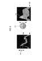
FIG 6 is a schematic diagram showing another example of the additional information. -
FIG 7 is a schematic diagram showing yet another example of the additional information. - A detailed description may be provided with reference to the accompanying drawings. One of ordinary skill in the art may realize that the following description is illustrative only and is not in any way limiting.
- Referring to
FIG 1 , anultrasound system 100 in accordance with an illustrative embodiment is shown. As depicted therein, theultrasound system 100 includes auser input unit 110. - The
user input unit 110 is configured to receive input information. In the embodiment, the input information includes sample volume setting information for setting a sample volume SV on a brightness mode image BI, as shown inFIG 2 . However, it should be noted herein that the input information may not be limited thereto. InFIG 2 , reference numeral BV represents a blood vessel. Theuser input unit 110 includes a control panel, a trackball, a mouse, a keyboard and the like. - The
ultrasound system 100 further includes an ultrasounddata acquisition unit 120. Theultrasound acquisition unit 120 is configured to transmit ultrasound signals to a living body. The living body includes target objects (e.g., blood flow, a heart, etc.). Theultrasound acquisition unit 120 may be further configured to receive ultrasound signals (i.e., ultrasound echo signals) from the living body to acquire ultrasound data.FIG 3 is a block diagram showing an illustrative embodiment of the ultrasound data acquisition unit. Referring toFIG 3 , the ultrasounddata acquisition unit 120 includes anultrasound probe 310. - The
ultrasound probe 310 includes a plurality of transducer elements (not shown) for reciprocally converting between ultrasound signals and electrical signals. Theultrasound probe 310 is configured to transmit the ultrasound signals to the living body. Theultrasound probe 310 is further configured to receive the ultrasound echo signals from the living body to output received signals. The received signals are analog signals. Theultrasound probe 310 includes a convex probe, a linear probe and the like. - The ultrasound
data acquisition unit 120 further includes a transmittingsection 320. The transmittingsection 320 is configured to control the transmission of the ultrasound signals. The transmittingsection 320 is further configured to generate electrical signals ("transmitting signals") for obtaining an ultrasound image in consideration of the elements and focusing points. The transmittingsection 320 includes a transmitting signal generating section (not shown), a transmitting delay information memory (not shown), a transmitting beam former (not shown) and the like. - In the embodiment, the transmitting
section 320 generates first transmitting signals for obtaining the brightness mode image BI. Thus, theultrasound probe 310 converts the first transmitting signals into the ultrasound signals, transmits the ultrasound signals to the living body and receives the ultrasound echo signals from the living body to thereby output first received signals. The transmittingsection 320 further generates second transmitting signals for obtaining a Doppler spectrum image corresponding to the sample volume SV Thus, theultrasound probe 310 converts the second transmitting signals into the ultrasound signals, transmit the ultrasound signals to the living body and receive the ultrasound echo signals from the living body to thereby output second received signals. - The ultrasound
data acquisition unit 120 further includes areceiving section 330. Thereceiving section 330 is configured to convert the received signals into digital signals. Thereceiving section 330 is further configured to apply delays to the digital signals in consideration of the elements and the focusing points to thereby output digital receive-focused signals. Thereceiving section 330 includes an analog-to-digital converter (not shown), a receiving delay time information memory (not shown), a receiving beam former (not shown) and the like. - In the embodiment, the
receiving section 330 converts the first received signals provided from theultrasound probe 310 into first digital signals. Thereceiving section 330 further applies delays to the first digital signals in consideration of the elements and the focusing points to thereby output first digital receive-focused signals. The receivingsection 330 further converts the second received signals provided from theultrasound probe 310 into second digital signals. The receivingsection 330 further applies delays to the second digital signals in consideration of the elements and the focusing points to thereby output second digital receive-focused signals. - The ultrasound
data acquisition unit 120 further includes an ultrasounddata forming section 340. The ultrasounddata forming section 340 is configured to form ultrasound data corresponding to the ultrasound image based on the digital receive-focused signals provided from thereceiving section 330. The ultrasounddata forming section 340 is further configured to perform a signal process (e.g., gain control, etc) upon the digital receive-focused signals. - In the embodiment, the ultrasound
data forming section 340 forms first ultrasound data corresponding to the brightness mode image BI based on the first digital receive-focused signals provided from the receivingsection 330. The first ultrasound data include radio frequency data. However, it should be noted herein that the first ultrasound data may not be limited thereto. The ultrasounddata forming section 340 further forms second ultrasound data corresponding to the sample volume SV (i.e., Doppler spectrum image) based on the second digital receive-focused signals provided from the receivingsection 330. The second ultrasound data include the radio frequency data or in-phase/quadrature data. However, it should be noted herein that the second ultrasound data may not be limited thereto. - Referring back to
FIG 1 , theultrasound system 100 further includes aprocessing unit 130 in communication with theuser input unit 110 and the ultrasounddata acquisition unit 120. Theprocessing unit 130 includes a central processing unit, a microprocessor, a graphic processing unit and the like. -
FIG 4 is a flow chart showing a process of forming additional information. Theprocessing unit 130 is configure to form the brightness mode image BI based on the first ultrasound data provided from the ultrasounddata acquisition unit 120, at step S402 inFIG 4 . The brightness mode image BI is displayed on adisplay unit 150. Thus, the user sets the sample volume SV on the brightness mode image BI by using theuser input unit 110. - The
processing unit 130 is configured to set the sample volume SV on the brightness mode image BI as shown inFIG 2 , based on the input information provided from theuser input unit 110, at step S404 inFIG. 4 . Thus, the ultrasounddata acquisition unit 120 acquires the second ultrasound data corresponding to the sample volume SV. - The
processing unit 130 is configured to form information (hereinafter, "blood flow information") corresponding to a moving target object (i.e., blood flow) in the living body based on the second ultrasound data provided from the ultrasounddata acquisition unit 120, at step S406 inFIG 4 . In the embodiment, the blood flow information includes blood flow velocity information, blood flow rate information, blood flow velocity distribution information and the like. The methods of forming the blood flow information are well known in the art. Thus, they have not been described in detail so as not to unnecessarily obscure the present invention. - The
processing unit 130 is configured to form the Doppler spectrum image based on the blood flow information, at step S408 inFIG 4 . The methods of forming the Doppler spectrum image are well known in the art. Thus, they have not been described in detail so as not to unnecessarily obscure the present invention. - The
processing unit 130 is configured to form additional information based on the blood flow information, at step S410 inFIG 4 . The additional information is information for representing a change of the blood flow with a time. - As one example, the
processing unit 130 forms a color map CM as the additional information based on the blood flow information, as shown inFIG 5 . The color map CM is formed by mapping a plurality of blood flow velocities (i.e., height of Doppler spectrum) to colors. - As another example, the
processing unit 130 forms a color Doppler spectrum image PWI as the additional information based on the blood flow information, as shown inFIG 5 . The color Doppler spectrum image PWI is formed by mapping the colors corresponding to the color map CM to the Doppler spectrum image. That is, the color Doppler spectrum image PWI is formed by applying the colors corresponding to the blood flow velocities to pixels of the Doppler spectrum image. - As yet another example, the
processing unit 130 forms a color blood flow velocity image CI as the additional information based on the blood flow information, as shown inFIG 5 . The color blood flow velocity image CI is formed by mapping the blood flow velocity to the color. That is, the color blood flow velocity image CI is formed by mapping the blood flow velocity corresponding to current blood flow information to the color. - Although it is described that the
processing unit 130 forms the color map, the color Doppler spectrum image or the color blood flow velocity image, theprocessing unit 130 forms at least one of the color map, the color Doppler spectrum image and the color blood flow velocity image. - As yet another example, the
processing unit 130 applies transparency corresponding to the blood flow rate to at least one of the color map, the color Doppler spectrum image and the color blood flow velocity image as the additional information, based on the blood flow information. That is, theprocessing unit 130 applies the transparency to the colors corresponding to the blood flow velocities based on the blood flow rate. - As yet another example, the
processing unit 130 forms a blood flowvelocity distribution image 610 as the additional information based on the blood flow information, as shown inFIG 6 . The blood flowvelocity distribution image 610 is an image for representing blood flow velocity distribution based on distribution of spots (i.e., width of Doppler spectrum). - As yet another example, the
processing unit 130 forms numeric information corresponding to the blood flow velocity and variance as the additional information based on the blood flow information. - Although it is described that the
processing unit 130 forms the Doppler spectrum image with the additional information based on the blood flow information, theprocessing unit 130 forms the additional information based on the blood flow information. - Also, although it is described that the sample volume SV is set on the brightness mode image BI and the additional information corresponding to the sample volume is provided, at least one sample volume (e.g., two sample volumes SV1, SV2 as shown in
FIG 7 ) is set on the brightness mode image BI and the additional information (e.g., color Doppler spectrum images PWI1, PWI2, color blood flow images CI1, CI2 and the like) corresponding to each of the sample volumes SV1, SV2. - Referring back to
FIG 1 , theultrasound system 100 further includes astorage unit 140. Thestorage unit 140 stores the ultrasound data (i.e., first ultrasound data and second ultrasound data) acquired by the ultrasounddata acquisition unit 120. Thestorage unit 140 further stores the input information received by theuser input unit 110. - The
ultrasound system 100 further includes thedisplay unit 150. Thedisplay unit 150 is configured to display the brightness mode image BI formed by theprocessing unit 130. Thedisplay unit 150 is further configured to display the Doppler spectrum image formed by theprocessing unit 130. Thedisplay unit 150 is further configured to display the additional information formed by theprocessing unit 130. - Although embodiments have been described with reference to a number of illustrative embodiments thereof, it should be understood that numerous other modifications and embodiments can be devised by those skilled in the art that will fall within the scope of the principles of this disclosure. More particularly, numerous variations and modifications are possible in the component parts and/or arrangements of the subject combination arrangement within the scope of the disclosure, the drawings and the appended claims. In addition to variations and modifications in the component parts and/or arrangements, alternative uses will also be apparent to those skilled in the art.
Claims (14)
- An ultrasound system, comprising:an ultrasound data acquisition unit configured to acquire first ultrasound data and second ultrasound data corresponding to a living body; anda processing unit configured to form a brightness mode image based on the first ultrasound data, set at least one sample volume on the brightness mode image and form blood flow information corresponding to blood flow in the living body based on the second ultrasound data corresponding to the at least one sample volume, the processing unit being further configured to form additional information corresponding to a change of the blood flow with a time based on the blood flow information.
- The ultrasound system of Claim 1, wherein the blood flow information includes blood flow velocity information, blood flow rate information and blood flow velocity distribution information.
- The ultrasound system of Claim 1, wherein the processing unit is configured to form at least one of a color map for mapping blood flow velocities to colors, a color blood flow velocity image for mapping a blood flow velocity to a color and a color Doppler spectrum image for mapping blood flow velocities to colors as the additional information based on the blood flow information.
- The ultrasound system of Claim 4, wherein the color blood flow velocity image is displayed on the at least one sample volume.
- The ultrasound system of Claim 1, wherein the processing unit is configured to apply transparency to at least one of a color map, a color Doppler spectrum image and a color blood flow velocity image as the additional information based on the blood flow information.
- The ultrasound system of Claim 1, wherein the processing unit is configured to form a blood flow velocity distribution for representing blood flow velocity distribution corresponding to distribution of spots as the additional information based on the blood flow information.
- The ultrasound system of Claim 1, wherein the processing unit is configured to form numeric information corresponding to blood flow velocity and variance as the additional information based on the blood flow information.
- A method of providing additional information, comprising:a) acquiring first ultrasound data corresponding to a living body;b) forming a brightness mode image based on the first ultrasound data;c) setting at least one sample volume on the brightness mode image;d) acquiring second ultrasound data corresponding to the at least one sample volume;e) forming blood flow information corresponding to blood flow in the living body based on the second ultrasound data corresponding to the at least one sample volume; andf) forming additional information corresponding to a change of the blood flow with a time based on the blood flow information.
- The method of Claim 8, wherein the blood flow information includes blood flow velocity information, blood flow rate information and blood flow velocity distribution information.
- The method of Claim 8, wherein the step f) comprises:forming at least one of a color map for mapping blood flow velocities to colors,a color blood flow velocity image for mapping a blood flow velocity to a color and a color Doppler spectrum image for mapping blood flow velocities to colors as the additional information based on the blood flow information.
- The method of Claim 10, wherein the color blood flow velocity image is displayed on the at least one sample volume.
- The method of Claim 8, wherein the step f) comprises:applying transparency to at least one of a color map, a color Doppler spectrum image and a color blood flow velocity image as the additional information base on the blood flow information.
- The method of Claim 8, wherein the step f) comprises:forming a blood flow velocity distribution for representing blood flow velocity distribution corresponding to distribution of spots as the additional information based on the blood flow information.
- The method of Claim 8, wherein the step f) comprises:forming numeric information corresponding to blood flow velocity andvariance as the additional information based on the blood flow information.
Applications Claiming Priority (1)
| Application Number | Priority Date | Filing Date | Title |
|---|---|---|---|
| KR1020100123899A KR101390186B1 (en) | 2010-12-07 | 2010-12-07 | Ultrasound system and method for providing additional information representing a change of blood flow over time |
Publications (2)
| Publication Number | Publication Date |
|---|---|
| EP2462872A1 true EP2462872A1 (en) | 2012-06-13 |
| EP2462872B1 EP2462872B1 (en) | 2019-09-18 |
Family
ID=45093524
Family Applications (1)
| Application Number | Title | Priority Date | Filing Date |
|---|---|---|---|
| EP11191707.6A Active EP2462872B1 (en) | 2010-12-07 | 2011-12-02 | Providing additional information corresponding to change of blood flow with a time in ultrasound system |
Country Status (4)
| Country | Link |
|---|---|
| US (1) | US9078590B2 (en) |
| EP (1) | EP2462872B1 (en) |
| JP (1) | JP2012120840A (en) |
| KR (1) | KR101390186B1 (en) |
Families Citing this family (8)
| Publication number | Priority date | Publication date | Assignee | Title |
|---|---|---|---|---|
| US10667790B2 (en) | 2012-03-26 | 2020-06-02 | Teratech Corporation | Tablet ultrasound system |
| US9877699B2 (en) | 2012-03-26 | 2018-01-30 | Teratech Corporation | Tablet ultrasound system |
| EP2989992B1 (en) | 2014-09-01 | 2022-11-16 | Samsung Medison Co., Ltd. | Medical imaging apparatus and method of generating medical image |
| EP2989986B1 (en) * | 2014-09-01 | 2019-12-18 | Samsung Medison Co., Ltd. | Ultrasound diagnosis apparatus and method of operating the same |
| CN110167449A (en) | 2016-11-16 | 2019-08-23 | 德拉工业公司 | Portable ultrasound system |
| JP7032111B2 (en) * | 2016-11-28 | 2022-03-08 | キヤノンメディカルシステムズ株式会社 | Medical image processing equipment, X-ray CT equipment and medical image processing program |
| WO2019195783A1 (en) * | 2018-04-05 | 2019-10-10 | The Regents Of The University Of California | Mapping and quantifying shear stress and hemolysis in patients having lvads |
| KR102923840B1 (en) * | 2023-06-02 | 2026-02-06 | 알피니언메디칼시스템 주식회사 | Apparatus for processing ultrasound image and method thereof |
Citations (4)
| Publication number | Priority date | Publication date | Assignee | Title |
|---|---|---|---|---|
| US5709211A (en) * | 1995-06-30 | 1998-01-20 | Fujitsu Limited | Ultrasonic diagnostic apparatus |
| US6077226A (en) * | 1999-03-30 | 2000-06-20 | General Electric Company | Method and apparatus for positioning region of interest in image |
| US20060241458A1 (en) * | 2003-07-22 | 2006-10-26 | Tetsuya Hayashi | Ultrasonographic device and ultrasonographic method |
| EP1977694A1 (en) * | 2007-04-06 | 2008-10-08 | Medison Co., Ltd. | Ultrasound system and method of forming an ultrasound image |
Family Cites Families (8)
| Publication number | Priority date | Publication date | Assignee | Title |
|---|---|---|---|---|
| JPH088920B2 (en) * | 1990-09-28 | 1996-01-31 | 富士通株式会社 | Blood scattering power calculator |
| US6177923B1 (en) * | 1994-12-30 | 2001-01-23 | Acuson Corporation | Imaging modality showing energy and velocity |
| US6592522B2 (en) * | 2001-06-12 | 2003-07-15 | Ge Medical Systems Global Technology Company, Llc | Ultrasound display of displacement |
| US7815572B2 (en) | 2003-02-13 | 2010-10-19 | Koninklijke Philips Electronics N.V. | Flow spectrograms synthesized from ultrasonic flow color doppler information |
| CN1890579B (en) * | 2003-12-03 | 2012-10-03 | 皇家飞利浦电子股份有限公司 | Ultrasonic imaging system for simultaneous display of blood flow and perfusion parameters |
| KR100825054B1 (en) * | 2005-06-28 | 2008-04-28 | 주식회사 메디슨 | How to image color flow images and ultrasound diagnostic system |
| KR100951595B1 (en) | 2006-10-17 | 2010-04-09 | 주식회사 메디슨 | Ultrasound System and Method for Forming Ultrasound Images |
| KR101060436B1 (en) * | 2007-09-04 | 2011-08-29 | 삼성메디슨 주식회사 | Ultrasound System and Method for Forming Ultrasound Images |
-
2010
- 2010-12-07 KR KR1020100123899A patent/KR101390186B1/en active Active
-
2011
- 2011-12-02 EP EP11191707.6A patent/EP2462872B1/en active Active
- 2011-12-05 US US13/311,274 patent/US9078590B2/en active Active
- 2011-12-06 JP JP2011267185A patent/JP2012120840A/en active Pending
Patent Citations (4)
| Publication number | Priority date | Publication date | Assignee | Title |
|---|---|---|---|---|
| US5709211A (en) * | 1995-06-30 | 1998-01-20 | Fujitsu Limited | Ultrasonic diagnostic apparatus |
| US6077226A (en) * | 1999-03-30 | 2000-06-20 | General Electric Company | Method and apparatus for positioning region of interest in image |
| US20060241458A1 (en) * | 2003-07-22 | 2006-10-26 | Tetsuya Hayashi | Ultrasonographic device and ultrasonographic method |
| EP1977694A1 (en) * | 2007-04-06 | 2008-10-08 | Medison Co., Ltd. | Ultrasound system and method of forming an ultrasound image |
Also Published As
| Publication number | Publication date |
|---|---|
| JP2012120840A (en) | 2012-06-28 |
| KR101390186B1 (en) | 2014-04-29 |
| KR20120062952A (en) | 2012-06-15 |
| US20120078108A1 (en) | 2012-03-29 |
| US9078590B2 (en) | 2015-07-14 |
| EP2462872B1 (en) | 2019-09-18 |
Similar Documents
| Publication | Publication Date | Title |
|---|---|---|
| US8684934B2 (en) | Adaptively performing clutter filtering in an ultrasound system | |
| US9261485B2 (en) | Providing color doppler image based on qualification curve information in ultrasound system | |
| EP2462872B1 (en) | Providing additional information corresponding to change of blood flow with a time in ultrasound system | |
| US11406362B2 (en) | Providing user interface in ultrasound system | |
| EP2444001A1 (en) | Providing an ultrasound spatial compound image based on a phased array probe in an ultrasound system | |
| EP2610635A2 (en) | Providing Doppler spectrum images corresponding to at least two sample volumes in ultrasound system | |
| EP2609871A1 (en) | Providing vector doppler image based on decision data in ultrasound system | |
| EP2610641B1 (en) | Ultrasound and system for forming a Doppler ultrasound image | |
| US20130165784A1 (en) | Providing motion profile information of target object in ultrasound system | |
| EP2609870A1 (en) | Providing turbulent flow information based on vector doppler in ultrasound system | |
| US9232932B2 (en) | Providing motion mode image in ultrasound system | |
| US9510803B2 (en) | Providing compound image of doppler spectrum images in ultrasound system | |
| EP2392945A2 (en) | Providing a motion image in an ultrasound system | |
| EP2610638B1 (en) | Forming vector information based on vector doppler in ultrasound system | |
| EP2425784B1 (en) | Providing a color Doppler mode image in an ultrasound system | |
| EP2466332A2 (en) | Performing receive-focusing based on mid-point algorithm in ultrasound system | |
| EP2609869A1 (en) | Providing particle flow image in ultrasound system | |
| EP2610640A2 (en) | Ultrasound system and method for detecting vector information using transmission delays | |
| EP2386251A1 (en) | Providing at least one slice image with additional information in an ultrasound system | |
| EP2034332A2 (en) | Ultrasound system and method of forming a 3D ultrasound image indicating colour flow changes with respect to a reference velocity | |
| KR101055588B1 (en) | Ultrasound System and Method for Forming Ultrasound Images |
Legal Events
| Date | Code | Title | Description |
|---|---|---|---|
| PUAI | Public reference made under article 153(3) epc to a published international application that has entered the european phase |
Free format text: ORIGINAL CODE: 0009012 |
|
| AK | Designated contracting states |
Kind code of ref document: A1 Designated state(s): AL AT BE BG CH CY CZ DE DK EE ES FI FR GB GR HR HU IE IS IT LI LT LU LV MC MK MT NL NO PL PT RO RS SE SI SK SM TR |
|
| AX | Request for extension of the european patent |
Extension state: BA ME |
|
| 17P | Request for examination filed |
Effective date: 20121212 |
|
| 17Q | First examination report despatched |
Effective date: 20141023 |
|
| STAA | Information on the status of an ep patent application or granted ep patent |
Free format text: STATUS: EXAMINATION IS IN PROGRESS |
|
| GRAP | Despatch of communication of intention to grant a patent |
Free format text: ORIGINAL CODE: EPIDOSNIGR1 |
|
| STAA | Information on the status of an ep patent application or granted ep patent |
Free format text: STATUS: GRANT OF PATENT IS INTENDED |
|
| INTG | Intention to grant announced |
Effective date: 20190506 |
|
| GRAS | Grant fee paid |
Free format text: ORIGINAL CODE: EPIDOSNIGR3 |
|
| GRAA | (expected) grant |
Free format text: ORIGINAL CODE: 0009210 |
|
| STAA | Information on the status of an ep patent application or granted ep patent |
Free format text: STATUS: THE PATENT HAS BEEN GRANTED |
|
| AK | Designated contracting states |
Kind code of ref document: B1 Designated state(s): AL AT BE BG CH CY CZ DE DK EE ES FI FR GB GR HR HU IE IS IT LI LT LU LV MC MK MT NL NO PL PT RO RS SE SI SK SM TR |
|
| REG | Reference to a national code |
Ref country code: GB Ref legal event code: FG4D |
|
| REG | Reference to a national code |
Ref country code: CH Ref legal event code: EP |
|
| REG | Reference to a national code |
Ref country code: DE Ref legal event code: R096 Ref document number: 602011062115 Country of ref document: DE |
|
| REG | Reference to a national code |
Ref country code: AT Ref legal event code: REF Ref document number: 1180362 Country of ref document: AT Kind code of ref document: T Effective date: 20191015 |
|
| REG | Reference to a national code |
Ref country code: IE Ref legal event code: FG4D |
|
| REG | Reference to a national code |
Ref country code: NL Ref legal event code: MP Effective date: 20190918 |
|
| PG25 | Lapsed in a contracting state [announced via postgrant information from national office to epo] |
Ref country code: HR Free format text: LAPSE BECAUSE OF FAILURE TO SUBMIT A TRANSLATION OF THE DESCRIPTION OR TO PAY THE FEE WITHIN THE PRESCRIBED TIME-LIMIT Effective date: 20190918 Ref country code: LT Free format text: LAPSE BECAUSE OF FAILURE TO SUBMIT A TRANSLATION OF THE DESCRIPTION OR TO PAY THE FEE WITHIN THE PRESCRIBED TIME-LIMIT Effective date: 20190918 Ref country code: SE Free format text: LAPSE BECAUSE OF FAILURE TO SUBMIT A TRANSLATION OF THE DESCRIPTION OR TO PAY THE FEE WITHIN THE PRESCRIBED TIME-LIMIT Effective date: 20190918 Ref country code: BG Free format text: LAPSE BECAUSE OF FAILURE TO SUBMIT A TRANSLATION OF THE DESCRIPTION OR TO PAY THE FEE WITHIN THE PRESCRIBED TIME-LIMIT Effective date: 20191218 Ref country code: FI Free format text: LAPSE BECAUSE OF FAILURE TO SUBMIT A TRANSLATION OF THE DESCRIPTION OR TO PAY THE FEE WITHIN THE PRESCRIBED TIME-LIMIT Effective date: 20190918 Ref country code: NO Free format text: LAPSE BECAUSE OF FAILURE TO SUBMIT A TRANSLATION OF THE DESCRIPTION OR TO PAY THE FEE WITHIN THE PRESCRIBED TIME-LIMIT Effective date: 20191218 |
|
| REG | Reference to a national code |
Ref country code: LT Ref legal event code: MG4D |
|
| PG25 | Lapsed in a contracting state [announced via postgrant information from national office to epo] |
Ref country code: RS Free format text: LAPSE BECAUSE OF FAILURE TO SUBMIT A TRANSLATION OF THE DESCRIPTION OR TO PAY THE FEE WITHIN THE PRESCRIBED TIME-LIMIT Effective date: 20190918 Ref country code: GR Free format text: LAPSE BECAUSE OF FAILURE TO SUBMIT A TRANSLATION OF THE DESCRIPTION OR TO PAY THE FEE WITHIN THE PRESCRIBED TIME-LIMIT Effective date: 20191219 Ref country code: LV Free format text: LAPSE BECAUSE OF FAILURE TO SUBMIT A TRANSLATION OF THE DESCRIPTION OR TO PAY THE FEE WITHIN THE PRESCRIBED TIME-LIMIT Effective date: 20190918 Ref country code: AL Free format text: LAPSE BECAUSE OF FAILURE TO SUBMIT A TRANSLATION OF THE DESCRIPTION OR TO PAY THE FEE WITHIN THE PRESCRIBED TIME-LIMIT Effective date: 20190918 |
|
| REG | Reference to a national code |
Ref country code: AT Ref legal event code: MK05 Ref document number: 1180362 Country of ref document: AT Kind code of ref document: T Effective date: 20190918 |
|
| PG25 | Lapsed in a contracting state [announced via postgrant information from national office to epo] |
Ref country code: RO Free format text: LAPSE BECAUSE OF FAILURE TO SUBMIT A TRANSLATION OF THE DESCRIPTION OR TO PAY THE FEE WITHIN THE PRESCRIBED TIME-LIMIT Effective date: 20190918 Ref country code: EE Free format text: LAPSE BECAUSE OF FAILURE TO SUBMIT A TRANSLATION OF THE DESCRIPTION OR TO PAY THE FEE WITHIN THE PRESCRIBED TIME-LIMIT Effective date: 20190918 Ref country code: NL Free format text: LAPSE BECAUSE OF FAILURE TO SUBMIT A TRANSLATION OF THE DESCRIPTION OR TO PAY THE FEE WITHIN THE PRESCRIBED TIME-LIMIT Effective date: 20190918 Ref country code: AT Free format text: LAPSE BECAUSE OF FAILURE TO SUBMIT A TRANSLATION OF THE DESCRIPTION OR TO PAY THE FEE WITHIN THE PRESCRIBED TIME-LIMIT Effective date: 20190918 Ref country code: PL Free format text: LAPSE BECAUSE OF FAILURE TO SUBMIT A TRANSLATION OF THE DESCRIPTION OR TO PAY THE FEE WITHIN THE PRESCRIBED TIME-LIMIT Effective date: 20190918 Ref country code: ES Free format text: LAPSE BECAUSE OF FAILURE TO SUBMIT A TRANSLATION OF THE DESCRIPTION OR TO PAY THE FEE WITHIN THE PRESCRIBED TIME-LIMIT Effective date: 20190918 Ref country code: PT Free format text: LAPSE BECAUSE OF FAILURE TO SUBMIT A TRANSLATION OF THE DESCRIPTION OR TO PAY THE FEE WITHIN THE PRESCRIBED TIME-LIMIT Effective date: 20200120 |
|
| PG25 | Lapsed in a contracting state [announced via postgrant information from national office to epo] |
Ref country code: IS Free format text: LAPSE BECAUSE OF FAILURE TO SUBMIT A TRANSLATION OF THE DESCRIPTION OR TO PAY THE FEE WITHIN THE PRESCRIBED TIME-LIMIT Effective date: 20200224 Ref country code: SK Free format text: LAPSE BECAUSE OF FAILURE TO SUBMIT A TRANSLATION OF THE DESCRIPTION OR TO PAY THE FEE WITHIN THE PRESCRIBED TIME-LIMIT Effective date: 20190918 Ref country code: SM Free format text: LAPSE BECAUSE OF FAILURE TO SUBMIT A TRANSLATION OF THE DESCRIPTION OR TO PAY THE FEE WITHIN THE PRESCRIBED TIME-LIMIT Effective date: 20190918 Ref country code: CZ Free format text: LAPSE BECAUSE OF FAILURE TO SUBMIT A TRANSLATION OF THE DESCRIPTION OR TO PAY THE FEE WITHIN THE PRESCRIBED TIME-LIMIT Effective date: 20190918 |
|
| REG | Reference to a national code |
Ref country code: DE Ref legal event code: R097 Ref document number: 602011062115 Country of ref document: DE |
|
| PLBE | No opposition filed within time limit |
Free format text: ORIGINAL CODE: 0009261 |
|
| STAA | Information on the status of an ep patent application or granted ep patent |
Free format text: STATUS: NO OPPOSITION FILED WITHIN TIME LIMIT |
|
| PG2D | Information on lapse in contracting state deleted |
Ref country code: IS |
|
| PG25 | Lapsed in a contracting state [announced via postgrant information from national office to epo] |
Ref country code: DK Free format text: LAPSE BECAUSE OF FAILURE TO SUBMIT A TRANSLATION OF THE DESCRIPTION OR TO PAY THE FEE WITHIN THE PRESCRIBED TIME-LIMIT Effective date: 20190918 Ref country code: IS Free format text: LAPSE BECAUSE OF FAILURE TO SUBMIT A TRANSLATION OF THE DESCRIPTION OR TO PAY THE FEE WITHIN THE PRESCRIBED TIME-LIMIT Effective date: 20200119 |
|
| REG | Reference to a national code |
Ref country code: CH Ref legal event code: PL |
|
| 26N | No opposition filed |
Effective date: 20200619 |
|
| REG | Reference to a national code |
Ref country code: BE Ref legal event code: MM Effective date: 20191231 |
|
| PG25 | Lapsed in a contracting state [announced via postgrant information from national office to epo] |
Ref country code: MC Free format text: LAPSE BECAUSE OF FAILURE TO SUBMIT A TRANSLATION OF THE DESCRIPTION OR TO PAY THE FEE WITHIN THE PRESCRIBED TIME-LIMIT Effective date: 20190918 Ref country code: SI Free format text: LAPSE BECAUSE OF FAILURE TO SUBMIT A TRANSLATION OF THE DESCRIPTION OR TO PAY THE FEE WITHIN THE PRESCRIBED TIME-LIMIT Effective date: 20190918 |
|
| GBPC | Gb: european patent ceased through non-payment of renewal fee |
Effective date: 20191218 |
|
| PG25 | Lapsed in a contracting state [announced via postgrant information from national office to epo] |
Ref country code: LU Free format text: LAPSE BECAUSE OF NON-PAYMENT OF DUE FEES Effective date: 20191202 Ref country code: GB Free format text: LAPSE BECAUSE OF NON-PAYMENT OF DUE FEES Effective date: 20191218 Ref country code: IE Free format text: LAPSE BECAUSE OF NON-PAYMENT OF DUE FEES Effective date: 20191202 |
|
| PG25 | Lapsed in a contracting state [announced via postgrant information from national office to epo] |
Ref country code: CH Free format text: LAPSE BECAUSE OF NON-PAYMENT OF DUE FEES Effective date: 20191231 Ref country code: BE Free format text: LAPSE BECAUSE OF NON-PAYMENT OF DUE FEES Effective date: 20191231 Ref country code: LI Free format text: LAPSE BECAUSE OF NON-PAYMENT OF DUE FEES Effective date: 20191231 |
|
| PG25 | Lapsed in a contracting state [announced via postgrant information from national office to epo] |
Ref country code: CY Free format text: LAPSE BECAUSE OF FAILURE TO SUBMIT A TRANSLATION OF THE DESCRIPTION OR TO PAY THE FEE WITHIN THE PRESCRIBED TIME-LIMIT Effective date: 20190918 |
|
| PG25 | Lapsed in a contracting state [announced via postgrant information from national office to epo] |
Ref country code: MT Free format text: LAPSE BECAUSE OF FAILURE TO SUBMIT A TRANSLATION OF THE DESCRIPTION OR TO PAY THE FEE WITHIN THE PRESCRIBED TIME-LIMIT Effective date: 20190918 Ref country code: HU Free format text: LAPSE BECAUSE OF FAILURE TO SUBMIT A TRANSLATION OF THE DESCRIPTION OR TO PAY THE FEE WITHIN THE PRESCRIBED TIME-LIMIT; INVALID AB INITIO Effective date: 20111202 |
|
| PG25 | Lapsed in a contracting state [announced via postgrant information from national office to epo] |
Ref country code: TR Free format text: LAPSE BECAUSE OF FAILURE TO SUBMIT A TRANSLATION OF THE DESCRIPTION OR TO PAY THE FEE WITHIN THE PRESCRIBED TIME-LIMIT Effective date: 20190918 |
|
| PG25 | Lapsed in a contracting state [announced via postgrant information from national office to epo] |
Ref country code: MK Free format text: LAPSE BECAUSE OF FAILURE TO SUBMIT A TRANSLATION OF THE DESCRIPTION OR TO PAY THE FEE WITHIN THE PRESCRIBED TIME-LIMIT Effective date: 20190918 |
|
| PGFP | Annual fee paid to national office [announced via postgrant information from national office to epo] |
Ref country code: DE Payment date: 20251105 Year of fee payment: 15 |
|
| PGFP | Annual fee paid to national office [announced via postgrant information from national office to epo] |
Ref country code: IT Payment date: 20251106 Year of fee payment: 15 |
|
| PGFP | Annual fee paid to national office [announced via postgrant information from national office to epo] |
Ref country code: FR Payment date: 20251111 Year of fee payment: 15 |