EP2425784B1 - Providing a color Doppler mode image in an ultrasound system - Google Patents
Providing a color Doppler mode image in an ultrasound system Download PDFInfo
- Publication number
- EP2425784B1 EP2425784B1 EP11176129.2A EP11176129A EP2425784B1 EP 2425784 B1 EP2425784 B1 EP 2425784B1 EP 11176129 A EP11176129 A EP 11176129A EP 2425784 B1 EP2425784 B1 EP 2425784B1
- Authority
- EP
- European Patent Office
- Prior art keywords
- value
- pivot point
- contrast stretching
- threshold value
- brightness
- Prior art date
- Legal status (The legal status is an assumption and is not a legal conclusion. Google has not performed a legal analysis and makes no representation as to the accuracy of the status listed.)
- Active
Links
- 238000002604 ultrasonography Methods 0.000 title claims description 122
- 238000000034 method Methods 0.000 claims description 37
- 210000004204 blood vessel Anatomy 0.000 claims description 9
- 230000000877 morphologic effect Effects 0.000 claims description 6
- 238000007781 pre-processing Methods 0.000 claims description 5
- 238000004891 communication Methods 0.000 claims description 3
- 239000000523 sample Substances 0.000 description 12
- 238000010586 diagram Methods 0.000 description 8
- 230000003321 amplification Effects 0.000 description 3
- 150000001875 compounds Chemical class 0.000 description 3
- 230000001934 delay Effects 0.000 description 3
- 230000003628 erosive effect Effects 0.000 description 3
- 238000003199 nucleic acid amplification method Methods 0.000 description 3
- 238000004458 analytical method Methods 0.000 description 2
- 230000017531 blood circulation Effects 0.000 description 2
- 239000003086 colorant Substances 0.000 description 2
- 230000007423 decrease Effects 0.000 description 2
- 230000010339 dilation Effects 0.000 description 2
- 230000000694 effects Effects 0.000 description 2
- 238000012285 ultrasound imaging Methods 0.000 description 2
- 230000005540 biological transmission Effects 0.000 description 1
- 238000013329 compounding Methods 0.000 description 1
- 230000001066 destructive effect Effects 0.000 description 1
- 229940079593 drug Drugs 0.000 description 1
- 239000003814 drug Substances 0.000 description 1
- 238000003379 elimination reaction Methods 0.000 description 1
- 230000002708 enhancing effect Effects 0.000 description 1
- 210000000056 organ Anatomy 0.000 description 1
- 230000003595 spectral effect Effects 0.000 description 1
Images


Classifications
-
- G—PHYSICS
- G01—MEASURING; TESTING
- G01S—RADIO DIRECTION-FINDING; RADIO NAVIGATION; DETERMINING DISTANCE OR VELOCITY BY USE OF RADIO WAVES; LOCATING OR PRESENCE-DETECTING BY USE OF THE REFLECTION OR RERADIATION OF RADIO WAVES; ANALOGOUS ARRANGEMENTS USING OTHER WAVES
- G01S7/00—Details of systems according to groups G01S13/00, G01S15/00, G01S17/00
- G01S7/52—Details of systems according to groups G01S13/00, G01S15/00, G01S17/00 of systems according to group G01S15/00
- G01S7/52017—Details of systems according to groups G01S13/00, G01S15/00, G01S17/00 of systems according to group G01S15/00 particularly adapted to short-range imaging
- G01S7/52053—Display arrangements
- G01S7/52057—Cathode ray tube displays
- G01S7/52071—Multicolour displays; using colour coding; Optimising colour or information content in displays, e.g. parametric imaging
-
- A—HUMAN NECESSITIES
- A61—MEDICAL OR VETERINARY SCIENCE; HYGIENE
- A61B—DIAGNOSIS; SURGERY; IDENTIFICATION
- A61B8/00—Diagnosis using ultrasonic, sonic or infrasonic waves
- A61B8/52—Devices using data or image processing specially adapted for diagnosis using ultrasonic, sonic or infrasonic waves
- A61B8/5269—Devices using data or image processing specially adapted for diagnosis using ultrasonic, sonic or infrasonic waves involving detection or reduction of artifacts
-
- G—PHYSICS
- G06—COMPUTING; CALCULATING OR COUNTING
- G06T—IMAGE DATA PROCESSING OR GENERATION, IN GENERAL
- G06T7/00—Image analysis
- G06T7/10—Segmentation; Edge detection
- G06T7/11—Region-based segmentation
-
- G—PHYSICS
- G06—COMPUTING; CALCULATING OR COUNTING
- G06T—IMAGE DATA PROCESSING OR GENERATION, IN GENERAL
- G06T7/00—Image analysis
- G06T7/10—Segmentation; Edge detection
- G06T7/155—Segmentation; Edge detection involving morphological operators
-
- G—PHYSICS
- G06—COMPUTING; CALCULATING OR COUNTING
- G06T—IMAGE DATA PROCESSING OR GENERATION, IN GENERAL
- G06T7/00—Image analysis
- G06T7/10—Segmentation; Edge detection
- G06T7/194—Segmentation; Edge detection involving foreground-background segmentation
-
- A—HUMAN NECESSITIES
- A61—MEDICAL OR VETERINARY SCIENCE; HYGIENE
- A61B—DIAGNOSIS; SURGERY; IDENTIFICATION
- A61B8/00—Diagnosis using ultrasonic, sonic or infrasonic waves
- A61B8/08—Detecting organic movements or changes, e.g. tumours, cysts, swellings
- A61B8/0891—Detecting organic movements or changes, e.g. tumours, cysts, swellings for diagnosis of blood vessels
-
- A—HUMAN NECESSITIES
- A61—MEDICAL OR VETERINARY SCIENCE; HYGIENE
- A61B—DIAGNOSIS; SURGERY; IDENTIFICATION
- A61B8/00—Diagnosis using ultrasonic, sonic or infrasonic waves
- A61B8/46—Ultrasonic, sonic or infrasonic diagnostic devices with special arrangements for interfacing with the operator or the patient
- A61B8/467—Ultrasonic, sonic or infrasonic diagnostic devices with special arrangements for interfacing with the operator or the patient characterised by special input means
- A61B8/469—Ultrasonic, sonic or infrasonic diagnostic devices with special arrangements for interfacing with the operator or the patient characterised by special input means for selection of a region of interest
-
- G—PHYSICS
- G01—MEASURING; TESTING
- G01S—RADIO DIRECTION-FINDING; RADIO NAVIGATION; DETERMINING DISTANCE OR VELOCITY BY USE OF RADIO WAVES; LOCATING OR PRESENCE-DETECTING BY USE OF THE REFLECTION OR RERADIATION OF RADIO WAVES; ANALOGOUS ARRANGEMENTS USING OTHER WAVES
- G01S15/00—Systems using the reflection or reradiation of acoustic waves, e.g. sonar systems
- G01S15/88—Sonar systems specially adapted for specific applications
- G01S15/89—Sonar systems specially adapted for specific applications for mapping or imaging
- G01S15/8906—Short-range imaging systems; Acoustic microscope systems using pulse-echo techniques
- G01S15/8979—Combined Doppler and pulse-echo imaging systems
-
- G—PHYSICS
- G06—COMPUTING; CALCULATING OR COUNTING
- G06T—IMAGE DATA PROCESSING OR GENERATION, IN GENERAL
- G06T2207/00—Indexing scheme for image analysis or image enhancement
- G06T2207/10—Image acquisition modality
- G06T2207/10132—Ultrasound image
- G06T2207/10136—3D ultrasound image
Definitions
- the present disclosure generally relates to ultrasound systems, and more particularly to providing a color Doppler mode image in an ultrasound system.
- An ultrasound system has become an important and popular diagnostic tool since it has a wide range of applications. Specifically, due to its non-invasive and non-destructive nature, the ultrasound system has been extensively used in the medical profession. Modem high-performance ultrasound systems and techniques are commonly used to produce two-dimensional or three-dimensional ultrasound images of internal features of an object (e.g., human organs).
- an object e.g., human organs
- the ultrasound system provides ultrasound images of various modes including a brightness mode (B mode) image representing reflection coefficients of the ultrasound signals reflected from a target object of a living body with a two-dimensional image, a Doppler mode image representing speed of a moving object with spectral Doppler by using a Doppler effect, a color Doppler mode image representing speed of a moving object with colors by using the Doppler effect, and an elastic mode image representing mechanical characteristics of tissues before and after applying a pressure thereto.
- the ultrasound system transmits and receives ultrasound signals to and from the target object to thereby form Doppler signals corresponding to a region of interest (ROI), which is set on a B mode image.
- the ultrasound system further forms a color Doppler mode image that represents the speed of the moving object with colors based on the Doppler signals.
- the ultrasound system performs a balance process to eliminate the color Doppler mode image corresponding to regions wherein a brightness value corresponding to a pixel of a brightness mode image is larger than a predetermined balance threshold value upon the color Doppler mode image. This is to remove color artifacts, which occurs by motion of regions such as blood-vessel walls, except interior spaces of the blood vessels, i.e., a lumen in which blood flows.
- a balance process cannot remove the color artifacts perfectly and decreases quality of the color Doppler mode image.
- the US 2005/059892A1 discloses an ultrasound imaging system lateral gain control circuit operating in conjunction with an ultrasound imaging system for generating an ultrasound image of an ultrasound analysis object using an ultrasound sensing circuit for sensing an ultrasound signal returning from an ultrasound analysis object to an ultrasound transducer.
- the ultrasound image is defined by a first region and a second region.
- the first region and second region together form the complete ultrasound image.
- the first region associates with a region proximate to the ultrasound transducer, while the second region associates with a region distal from the ultrasound transducer.
- the lateral gain control circuit controls the two-dimensional ultrasound image brightness between the two regions by controlling the ultrasound signal amplification by separately controlling the first region signal amplification and the second region signal amplification.
- an ultrasound system comprises: an ultrasound data acquisition unit configured to transmit and receive ultrasound signals to and from a living body to acquire first ultrasound data and second ultrasound data; a user input unit configured to receive input information corresponding to a region of interest and a balance threshold value having a predetermined brightness value; and a processing unit in communication with the ultrasound data acquisition unit and the user input unit, the processing unit being configured to form a brightness mode image and a color Doppler mode image corresponding to the region of interest based on the first and second ultrasound data, respectively, set a contrast stretching curve for securing connectivity of blood vessels of the living body based on the balance threshold value of the input information and the brightness mode image, form a mask for performing a balance process upon the color Doppler mode image based on the contrast stretching curve, and perform the balance process upon the color Doppler mode image based on the mask.
- a method of providing a color Doppler mode image, comprising: a) forming a brightness mode image based on first ultrasound data for a living body; b) receiving input information corresponding to a region of interest and a balance threshold value having a predetermined brightness value from a user; c) forming a color Doppler mode image corresponding to the region of interest based on second ultrasound data for the living body; d) setting a contrast stretching curve for securing connectivity of blood vessels of the living body based on the balance threshold value of the input information and the brightness mode image, and forming a mask for performing a balance process upon the color Doppler mode image based on the contrast stretching curve; and e) performing the balance process upon the color Doppler mode image based on the mask.
- the ultrasound system 100 includes a user input unit 110.
- the user input unit 110 is configured to receive input information for a user.
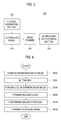
- the input information includes first input information for setting a region of interest (ROI) 220 on a brightness mode image 210 as shown in FIG. 2 .
- the ROI 220 includes a color box for obtaining a color Doppler mode image.
- the input information further includes second input information for setting a threshold value having a predetermined brightness value ("balance threshold value") for performing a balance processing upon the color Doppler mode image corresponding to the ROI 220.
- the user input unit 110 includes a control panel, a track ball, a mouse, a keyboard and the like.
- the ultrasound system 100 further includes an ultrasound data acquisition unit 120.
- the ultrasound data acquisition unit 120 is configured to transmit and receive ultrasound signals to and from a living body and output ultrasound data.
- the living body includes a plurality of target objects (e.g., blood vessels, heart, etc.).
- FIG. 3 is a block diagram showing an illustrative embodiment of the ultrasound data acquisition unit 120.
- the ultrasound data acquisition unit 120 includes an ultrasound probe 310.
- the ultrasound probe 310 includes a plurality of elements (not shown) for reciprocally converting between ultrasound signals and electrical signals.
- the ultrasound probe 310 is configured to transmit ultrasound signals to the living body.
- the ultrasound probe 310 is further configured to receive ultrasound signals (i.e., ultrasound echo signals) from the living body to output received signals.
- the received signals are analog signals.
- the ultrasound probe 310 includes a convex probe, a linear probe and the like.
- the ultrasound data acquisition unit 120 further includes a transmit (Tx) signal generating section 320.
- the Tx signal generating section 320 is configured to control the transmission of the ultrasound signals.
- the Tx signal generating section 320 is further configured to generate electrical signals ("Tx signals") for obtaining at least one ultrasound image in consideration of the elements and focal points.
- the Tx signal generating section 320 is configured to generate first Tx signals for obtaining the brightness mode image.
- the ultrasound probe 310 is configured to convert the first Tx signals provided from the Tx signal generating section 320 into the ultrasound signals, transmit the ultrasound signals to the living body and receive the ultrasound echo signals from the living body to thereby output first received signals.
- the Tx signal generating section 320 is further configured to generate second Tx signals for obtaining the color Doppler mode image based on a predetermined ensemble number. The ensemble number represents the number of transmitting and receiving ultrasound signals in order to obtain Doppler signals corresponding to each of the scan-lines.
- the ultrasound probe 310 is configured to convert the second Tx signals provided from the Tx signal generating section 320 into the ultrasound signals, transmit the ultrasound signals to the living body and receive the ultrasound echo signals from the living body to thereby output second received signals.
- the ultrasound data acquisition unit 120 further includes a beam former 330.
- the beam former 330 is configured to convert the received signals provided from the ultrasound probe 310 into digital signals.
- the beam former 330 is further configured to apply delays to the digital signals in consideration of the elements and the focal points to thereby output digital receive-focused signals.
- the beam former 330 is configured to convert the first received signals provided the ultrasound probe 310 into first digital signals.
- the beam former 330 is further configured to apply delays to the first digital signals in consideration of the elements and the focal points to output first digital receive-focused signals.
- the beam former 330 is configured to convert the second received signals provided from the ultrasound probe 310 into second digital signals.
- the beam former 330 is further configured to apply delays to the second digital signals in consideration of the elements and the focal points to output second digital receive-focused signals.
- the ultrasound data acquisition unit 120 further includes an ultrasound data forming section 340.
- the ultrasound data forming section 340 is configured to form ultrasound data based on the digital receive-focused signals provided from the beam former 330.
- the ultrasound data forming section 340 is further configured to perform signal processing (e.g., gain control, etc.) upon the digital receive-focused signals.
- the ultrasound data forming section 340 is configured to form first ultrasound data based on the first digital receive-focused signals provided from the beam former 330.
- the first ultrasound data includes radio frequency data.
- the ultrasound data forming section 340 is further configured to form second ultrasound data based on the second digital receive-focused signals provided from the beam former 330.
- the second ultrasound data includes in-phase/quadrature (IQ) data.
- IQ in-phase/quadrature
- the ultrasound data acquisition unit 120 is configured to acquire the ultrasound data by transmitting and receiving the ultrasound signals to and from the living body
- the ultrasound data acquisition unit 120 is further configured to acquire the ultrasound data from an external or internal storage unit (not shown) connected to the ultrasound system 100.
- the ultrasound system 100 further includes a processing unit 130 in communication with the user input unit 110 and the ultrasound data acquisition unit 120.
- the processing unit 130 includes a central processing unit, a microprocessor or a graphic processing unit. However, it should be noted herein that the processing unit 130 may not be limited thereto.
- FIG. 4 is a flow chart showing a process of performing the balance process upon the color Doppler mode image.
- the processing unit 130 is configured to form the brightness mode image based on the first ultrasound data provided from the ultrasound data acquisition unit 120 at step S402 in FIG. 4 .
- the brightness mode image is displayed on a display unit 150.
- the user sets the ROI on the brightness mode image displayed on the display unit 150 by using the user input unit 110.
- the processing unit 130 is configured to set the ROI on the brightness mode image based on the input information (i.e., first input information) provided from the user input unit 110 at step S404 in FIG. 4 .
- the ultrasound data acquisition unit 120 transmits and receives the ultrasound data to and from the living body to thereby acquire the second ultrasound data corresponding to the ROI.
- the processing unit 130 is configured to form the color Doppler mode image based on the second ultrasound data provided from the ultrasound data acquisition unit 120 at step S406 in FIG. 4 .
- the methods of the color Doppler mode image are well known in the art. Thus, they have not been described in detail so as not to unnecessarily obscure the present invention.
- the processing unit 130 is configured to form a mask ("balance mask") for performing the balance process upon the color Doppler mode image based on the input information (i.e., second input information) provided from the user input unit 110 and the brightness mode image at step S408 in FIG. 4 .
- a mask for performing the balance process upon the color Doppler mode image based on the input information (i.e., second input information) provided from the user input unit 110 and the brightness mode image at step S408 in FIG. 4 .
- FIG. 5 is a flow chart showing a process of forming the balance mask.
- the processing unit 130 is configured to perform a preprocessing upon the brightness mode image to eliminate unnecessary image data at step S502 in FIG. 5 .
- the preprocessing includes a noise elimination process by using an average filter. However, it should be noted herein that the preprocessing may not be limited thereto.
- the processing unit 130 is configured to set an image parameter based on the input information (i.e., second input information) provided from the user input unit 110 and the brightness mode image at step S504 in FIG. 5 .
- the image parameter is a parameter for forming the balance mask. That is, the image parameter is a parameter for securing connectivity of regions (e.g., blood vessels, tissues, etc.) except the inside space of the blood vessels, i.e., a lumen in which the blood flows.
- the processing unit 130 is configured to calculate a mean brightness value ("global mean brightness value") of pixels corresponding to the ROI of the brightness mode image based on brightness values corresponding to the pixels.
- the processing unit 130 is further configured to calculate a pivot point value of a contrast stretching curve for controlling brightness levels based on the second input information (i.e., balance threshold value) provided from the user input unit 110 and the global mean brightness value.
- PPV represents the pivot point value
- V GM represents the global mean brightness value
- BTV represents the balance threshold value
- V PPT represents a pivot point threshold value.
- the pivot point threshold value is a predetermined value in consideration of an application and type of the target object. For example, the pivot point threshold value is 0.8 to 1.2.
- the processing unit 130 is configured to calculate a gradient ("curvature") of the contrast stretching curve based on the second input information (i.e., balance threshold value) and the global mean brightness value. For example, the processing unit 130 detects a maximum brightness value from the brightness mode image. The processing unit 130 further calculates a difference between a predetermined brightness value and the maximum brightness value. The processing unit 130 further sets the difference as the gradient of the contrast stretching curve.
- w represents the gradient
- a represents a weight value, which is a predetermined value
- x represents a constant value
- d represent a different value between the mean brightness value (i.e., global mean brightness value or local mean brightness value) and the balance threshold value.
- the gradient becomes larger.
- the difference between the global mean brightness value and the balance threshold value gets smaller.
- the sign may not be limited thereto.
- the processing unit 130 is configured to set a sign of the contrast stretching curve based on the second input information (i.e., balance threshold value) and the pivot point value.
- the sign includes "+” and "-.” However, it should be noted herein that the sign may not be limited thereto.
- the processing unit 130 compares the balance threshold value with the pivot point value. If the balance value is equal to or larger than the pivot point value, then the processing unit 130 sets the sign as "+.” If the balance threshold value is smaller than the pivot point value, then the processing unit 130 sets the sign as "-.”
- the processing unit 130 is configured to set the image parameter based on the second input information, the global mean brightness value, the pivot point value, the gradient and the sign.
- the processing unit 130 sets a first contrast stretching curve SC 1 based on the balance threshold value BTV as shown in FIG. 6 .
- the processing unit 130 further calculates the pivot point value ("100") by applying the balance threshold value, the global mean brightness value and the pivot threshold value to equation 1.
- the processing unit 130 further calculates a difference between the balance brightness value and the global mean brightness value.
- the processing unit 130 further calculates the gradient W of the first contrast stretching curve SC 1 based on the calculated difference.
- the processing unit 130 further compares the balance threshold value with the pivot point value, and determines that the balance threshold value is equal to the pivot point value.
- the processing unit 130 further sets the sign of the first contrast stretching curve SC 1 as "+" based on the determining result.
- the processing unit 130 further sets a second contrast stretching curve SC 2 for setting the brightness values of regions corresponding to pixels that the brightness value is equal to or larger than 100 as a predetermined value (e.g., 255) based on the balance threshold value, the global mean brightness value, the pivot point value, the gradient and the sign, as shown in FIG. 6 .
- the processing unit 130 further sets the second contrast stretching curve SC 2 as the image parameter for forming the balance mask.
- the reference numeral PP represents a pivot point corresponding to the pivot point value.
- the image parameter shown in FIG. 6 is used to form the second contrast stretching curve SC 2 , which controls the brightness values of the brightness mode image. That is, the image parameter is used to decrease the brightness values under the pivot point value and increase the brightness values above the pivot point value.
- the processing unit 130 sets the first contrast stretching curve SC 1 based on the balance threshold value BTV as shown in FIG. 7 .
- the processing unit 130 further calculates the pivot point value (i.e., 85) by applying the balance threshold value (i.e., 100), the global mean brightness value (i.e., 100) and the pivot point threshold value (i.e., 0.85) to equation 1.
- the processing unit 130 further calculates a difference between the balance threshold value and the global mean brightness value.
- the processing unit 130 further calculates the gradient W of the first contrast stretching curve SC 1 based on the calculated difference as shown in FIG. 7 .
- the processing unit 130 further compares the balance threshold value with the pivot point value, and determines that the balance threshold value is larger than the pivot point value.
- the processing unit 130 further sets the sign of the first contrast stretching curve SC 1 as "+" based on the determining result.
- the processing unit 130 further sets the second contrast stretching curve SC 2 for setting the brightness values of regions corresponding to pixels that the brightness value is equal to or larger than 85 as a predetermined value (e.g., 255) based on the balance threshold value, the global mean brightness value, the pivot point value, the gradient and the sign, as shown in FIG. 7 .
- the processing unit 130 further sets the second contrast stretching curve SC 2 as the image parameter for forming the balance mask.
- the reference numeral PP represents the pivot point corresponding to the pivot point value.
- the processing unit 130 sets the first contrast stretching curve SC 1 based on the balance threshold value BTV as shown in FIG. 8 .
- the processing unit 130 further calculates the pivot point value (i.e., 82.5) by applying the balance threshold value (i.e., 100), the global mean brightness value (i.e., 50) and the pivot point threshold value (i.e., 1.1) to equation 1.
- the processing unit 130 further calculates a difference between the balance brightness value and the global mean brightness value.
- the processing unit 130 further calculates the gradient W of the first contrast stretching curve SC 1 based on the calculated difference as shown in FIG. 8 .
- the processing unit 130 compares the balance threshold value with the pivot point value, and determines that the balance threshold value is larger than the pivot point value.
- the processing unit 130 further sets the sign of the first contrast stretching curve SC 1 as "+” based on the determining result.
- the processing unit 130 additionally sets the second contrast stretching curve SC 2 for setting the brightness values of regions corresponding to pixels wherein the brightness value is equal to or larger than 82.5 as a predetermined value (e.g., 255) based on the balance threshold value, the global mean brightness value, the pivot point value, the gradient and the sign, as shown in FIG. 8 .
- the processing unit 130 further sets the second contrast stretching curve SC 2 as the image parameter for forming the balance mask.
- the reference numeral PP represents the pivot point corresponding to the pivot point value.
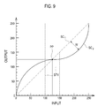
- the processing unit 130 sets the first contrast stretching curve SC 1 based on the balance threshold value BTV as shown in FIG. 9 .
- the processing unit 130 further calculates the pivot point value (i.e., 125) by applying the balance threshold value (i.e. 100), the global mean brightness value (i.e., 150) and the pivot point threshold value (i.e., 1.0) to equation 1.
- the processing unit 130 calculates a difference between the balance threshold value and the global mean brightness value.
- the processing unit 130 further calculates the gradient W of the first contrast stretching curve SC 1 based on the calculated difference as shown in FIG. 9 .
- the processing unit 130 further compares the balance threshold value with the pivot point value, and determines that the balance threshold value is smaller than the pivot point value.
- the processing unit 130 sets the sign of the first contrast stretching curve SC 1 as "-" based on the determining result.
- the processing unit 130 sets the second contrast stretching curve SC 2 for setting the brightness values of regions corresponding to pixels wherein the brightness value is equal to or larger than 125 as a predetermined value (e.g., 255) based on the balance threshold value, the global mean brightness value, the pivot point value, the gradient and the sign, as shown in FIG. 9 .
- the processing unit 130 further sets the second contrast stretching curve SC 2 as the image parameter for forming the balance mask.
- the reference numeral PP represents the pivot point corresponding to the pivot point value.
- the processing unit 130 is configured to calculate the global mean brightness value of pixels corresponding to the ROI of the brightness mode image based on the brightness values corresponding to the pixels.
- the processing unit 130 is further configured to divide the ROI into a plurality of regions. Each of the regions has at least one pixel.
- the processing unit 130 is further configured to calculate a mean brightness value ("local mean brightness value") of the at least one pixel corresponding to each of the regions.
- the processing unit 130 is further configured to calculate a mean brightness value of the global mean brightness value and the local mean brightness value.
- the processing unit 130 is configured to set the image parameter based on the mean brightness value and the second input information provided from the user input unit 110, as mentioned above.
- PPV represents the pivot point value
- V LM represents the local mean brightness value
- BTV represents the balance threshold value
- V PPT represents the pivot point threshold value
- the processing unit 130 is configured to calculate the gradient of the contrast stretching curve based on the second input information (i.e., balance threshold value) and the local mean brightness value for each of the regions, as mentioned above.
- the processing unit 130 is further configured to set the sign of the contrast stretching curve based on the second input information (i.e., balance brightness value) and the pivot point value, as mentioned above.
- the processing unit 130 is configured to set the image parameter based on the second input information, the local mean brightness value, the pivot point value, the gradient and the sign, as mentioned above.
- the processing unit 130 is configured to form the balance mask based on the image parameter at step S506 in FIG. 5 .
- the processing unit 130 performs an image process upon the brightness mode image based on the image parameter for setting the brightness values of regions corresponding to pixels wherein the brightness value is equal to or larger than the pivot point value as a predetermined value (e.g., 255) to form the balance mask.
- a predetermined value e.g. 255
- the processing unit 130 is configured to perform a morphological process for filling up empty space or enhancing connectivity upon the balance mask at step S508 in FIG. 5 .
- the morphological process is carried out by sequentially performing dilation and erosion. That is, the balance mask is removed as many as the predetermined number of pixels and then contracted (erosion).
- the processing unit 130 uses the dilation and erosion as the morphological process
- the processing unit 130 uses opening and closing as the morphological process.
- the processing unit 130 is configured to perform the balance process upon the color Doppler mode image by using the balance mask at step S410 in FIG. 4 .
- the processing unit 130 is configured to compound the brightness mode image and the balance-processed color Doppler mode image to form compound image at step S412 in FIG. 4 .
- the methods of compounding the brightness mode image and the color Doppler mode image are well known in the art. Thus, they have not been described in detail so as not to unnecessarily obscure the present invention.
- the ultrasound system 100 includes a storage unit 140.
- the storage unit 140 stores the input information (i.e., first input information and second input information) received by the user input unit 110.
- the storage unit 140 further stores the ultrasound data (i.e., first ultrasound data and second ultrasound data) acquired by the ultrasound data acquisition unit 120.
- the storage unit 140 further stores the brightness mode image formed by the processing unit 130.
- the storage unit 140 further stores the color Doppler mode image formed by the processing unit 130.
- the ultrasound system 100 includes the display unit 150.
- the display unit 150 displays the brightness mode image formed by the processing unit 130.
- the display unit 150 further displays the compound image formed by the processing unit 130.
- the display unit 150 further displays the color Doppler mode image formed by the processing unit 130.
Description
- The present application claims priority from
Korean Patent Application No. 10-2010-0085969 filed on September 2, 2010 - The present disclosure generally relates to ultrasound systems, and more particularly to providing a color Doppler mode image in an ultrasound system.
- An ultrasound system has become an important and popular diagnostic tool since it has a wide range of applications. Specifically, due to its non-invasive and non-destructive nature, the ultrasound system has been extensively used in the medical profession. Modem high-performance ultrasound systems and techniques are commonly used to produce two-dimensional or three-dimensional ultrasound images of internal features of an object (e.g., human organs).
- The ultrasound system provides ultrasound images of various modes including a brightness mode (B mode) image representing reflection coefficients of the ultrasound signals reflected from a target object of a living body with a two-dimensional image, a Doppler mode image representing speed of a moving object with spectral Doppler by using a Doppler effect, a color Doppler mode image representing speed of a moving object with colors by using the Doppler effect, and an elastic mode image representing mechanical characteristics of tissues before and after applying a pressure thereto. Particularly, the ultrasound system transmits and receives ultrasound signals to and from the target object to thereby form Doppler signals corresponding to a region of interest (ROI), which is set on a B mode image. The ultrasound system further forms a color Doppler mode image that represents the speed of the moving object with colors based on the Doppler signals.
- The ultrasound system performs a balance process to eliminate the color Doppler mode image corresponding to regions wherein a brightness value corresponding to a pixel of a brightness mode image is larger than a predetermined balance threshold value upon the color Doppler mode image. This is to remove color artifacts, which occurs by motion of regions such as blood-vessel walls, except interior spaces of the blood vessels, i.e., a lumen in which blood flows. However, this can be a problem since the conventional balance process cannot remove the color artifacts perfectly and decreases quality of the color Doppler mode image.
- The
US 2005/059892A1 discloses an ultrasound imaging system lateral gain control circuit operating in conjunction with an ultrasound imaging system for generating an ultrasound image of an ultrasound analysis object using an ultrasound sensing circuit for sensing an ultrasound signal returning from an ultrasound analysis object to an ultrasound transducer. The ultrasound image is defined by a first region and a second region. The first region and second region together form the complete ultrasound image. The first region associates with a region proximate to the ultrasound transducer, while the second region associates with a region distal from the ultrasound transducer. The lateral gain control circuit controls the two-dimensional ultrasound image brightness between the two regions by controlling the ultrasound signal amplification by separately controlling the first region signal amplification and the second region signal amplification. - Reference is also made to Jacinta E Browne et al: "Colour Doppler Spatial Resolution Performance Testing", Ultrasound, Royal Society of Medicine Press, GB, vol. 15, 1 August 2007 (2007-08-01), pages 162-166, XP007919778, ISSN: 1742-271X, D01: 10.1179/174313407X208677.
- Embodiments for providing a color Doppler mode image in an ultrasound system are disclosed herein. In one embodiment, according to
claim 1, an ultrasound system comprises: an ultrasound data acquisition unit configured to transmit and receive ultrasound signals to and from a living body to acquire first ultrasound data and second ultrasound data; a user input unit configured to receive input information corresponding to a region of interest and a balance threshold value having a predetermined brightness value; and a processing unit in communication with the ultrasound data acquisition unit and the user input unit, the processing unit being configured to form a brightness mode image and a color Doppler mode image corresponding to the region of interest based on the first and second ultrasound data, respectively, set a contrast stretching curve for securing connectivity of blood vessels of the living body based on the balance threshold value of the input information and the brightness mode image, form a mask for performing a balance process upon the color Doppler mode image based on the contrast stretching curve, and perform the balance process upon the color Doppler mode image based on the mask. - In another embodiment, there is provided a method according to claim 8 of providing a color Doppler mode image, comprising: a) forming a brightness mode image based on first ultrasound data for a living body; b) receiving input information corresponding to a region of interest and a balance threshold value having a predetermined brightness value from a user; c) forming a color Doppler mode image corresponding to the region of interest based on second ultrasound data for the living body; d) setting a contrast stretching curve for securing connectivity of blood vessels of the living body based on the balance threshold value of the input information and the brightness mode image, and forming a mask for performing a balance process upon the color Doppler mode image based on the contrast stretching curve; and e) performing the balance process upon the color Doppler mode image based on the mask.
-
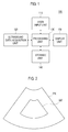
- FIG. 1
- is a block diagram showing an illustrative embodiment of an ultrasound system.
- FIG. 2
- is a schematic diagram showing an example of a brightness mode image and a region of interest.
- FIG. 3
- is a block diagram showing an illustrative embodiment of an ultrasound data acquisition unit.
- FIG. 4
- is a flow chart showing a process of performing a balance process upon a color Doppler mode image.
- FIG. 5
- is a flow chart showing a process of forming a balance mask.
- FIG. 6
- is a schematic diagram showing an example of an image parameter.
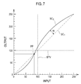
- FIG. 7
- is a schematic diagram showing another example of the image parameter.
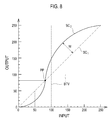
- FIG. 8
- is a schematic diagram showing yet another example of the image parameter.
- FIG. 9
- is a schematic diagram showing still yet another example of the image parameter.
- A detailed description may be provided with reference to the accompanying drawings. One of ordinary skill in the art may realize that the following description is illustrative only and is not in any way limiting.
- Referring to
FIG. 1 , anultrasound system 100 in accordance with an illustrative embodiment is shown. As depicted therein, theultrasound system 100 includes auser input unit 110. Theuser input unit 110 is configured to receive input information for a user. In one embodiment, the input information includes first input information for setting a region of interest (ROI) 220 on abrightness mode image 210 as shown inFIG. 2 . The ROI 220 includes a color box for obtaining a color Doppler mode image. The input information further includes second input information for setting a threshold value having a predetermined brightness value ("balance threshold value") for performing a balance processing upon the color Doppler mode image corresponding to theROI 220. However, it should be noted herein that the input information may not be limited thereto. Theuser input unit 110 includes a control panel, a track ball, a mouse, a keyboard and the like. - The
ultrasound system 100 further includes an ultrasounddata acquisition unit 120. The ultrasounddata acquisition unit 120 is configured to transmit and receive ultrasound signals to and from a living body and output ultrasound data. The living body includes a plurality of target objects (e.g., blood vessels, heart, etc.). -
FIG. 3 is a block diagram showing an illustrative embodiment of the ultrasounddata acquisition unit 120. Referring toFIG. 3 , the ultrasounddata acquisition unit 120 includes anultrasound probe 310. Theultrasound probe 310 includes a plurality of elements (not shown) for reciprocally converting between ultrasound signals and electrical signals. Theultrasound probe 310 is configured to transmit ultrasound signals to the living body. Theultrasound probe 310 is further configured to receive ultrasound signals (i.e., ultrasound echo signals) from the living body to output received signals. The received signals are analog signals. Theultrasound probe 310 includes a convex probe, a linear probe and the like. - The ultrasound
data acquisition unit 120 further includes a transmit (Tx) signal generatingsection 320. The Txsignal generating section 320 is configured to control the transmission of the ultrasound signals. The Txsignal generating section 320 is further configured to generate electrical signals ("Tx signals") for obtaining at least one ultrasound image in consideration of the elements and focal points. - In one embodiment, the Tx
signal generating section 320 is configured to generate first Tx signals for obtaining the brightness mode image. Thus, theultrasound probe 310 is configured to convert the first Tx signals provided from the Txsignal generating section 320 into the ultrasound signals, transmit the ultrasound signals to the living body and receive the ultrasound echo signals from the living body to thereby output first received signals. The Txsignal generating section 320 is further configured to generate second Tx signals for obtaining the color Doppler mode image based on a predetermined ensemble number. The ensemble number represents the number of transmitting and receiving ultrasound signals in order to obtain Doppler signals corresponding to each of the scan-lines. Thus, theultrasound probe 310 is configured to convert the second Tx signals provided from the Txsignal generating section 320 into the ultrasound signals, transmit the ultrasound signals to the living body and receive the ultrasound echo signals from the living body to thereby output second received signals. - The ultrasound
data acquisition unit 120 further includes a beam former 330. The beam former 330 is configured to convert the received signals provided from theultrasound probe 310 into digital signals. The beam former 330 is further configured to apply delays to the digital signals in consideration of the elements and the focal points to thereby output digital receive-focused signals. - In one embodiment, the beam former 330 is configured to convert the first received signals provided the
ultrasound probe 310 into first digital signals. The beam former 330 is further configured to apply delays to the first digital signals in consideration of the elements and the focal points to output first digital receive-focused signals. Also, the beam former 330 is configured to convert the second received signals provided from theultrasound probe 310 into second digital signals. The beam former 330 is further configured to apply delays to the second digital signals in consideration of the elements and the focal points to output second digital receive-focused signals. - The ultrasound
data acquisition unit 120 further includes an ultrasounddata forming section 340. The ultrasounddata forming section 340 is configured to form ultrasound data based on the digital receive-focused signals provided from the beam former 330. The ultrasounddata forming section 340 is further configured to perform signal processing (e.g., gain control, etc.) upon the digital receive-focused signals. - In one embodiment, the ultrasound
data forming section 340 is configured to form first ultrasound data based on the first digital receive-focused signals provided from the beam former 330. The first ultrasound data includes radio frequency data. However, it should be noted herein that the first ultrasound data may not be limited thereto. The ultrasounddata forming section 340 is further configured to form second ultrasound data based on the second digital receive-focused signals provided from the beam former 330. The second ultrasound data includes in-phase/quadrature (IQ) data. However, it should be noted herein that the second ultrasound data may not be limited thereto. - Although it is described above that the ultrasound
data acquisition unit 120 is configured to acquire the ultrasound data by transmitting and receiving the ultrasound signals to and from the living body, the ultrasounddata acquisition unit 120 is further configured to acquire the ultrasound data from an external or internal storage unit (not shown) connected to theultrasound system 100. - Referring back to
FIG. 1 , theultrasound system 100 further includes aprocessing unit 130 in communication with theuser input unit 110 and the ultrasounddata acquisition unit 120. Theprocessing unit 130 includes a central processing unit, a microprocessor or a graphic processing unit. However, it should be noted herein that theprocessing unit 130 may not be limited thereto. -
FIG. 4 is a flow chart showing a process of performing the balance process upon the color Doppler mode image. Theprocessing unit 130 is configured to form the brightness mode image based on the first ultrasound data provided from the ultrasounddata acquisition unit 120 at step S402 inFIG. 4 . The brightness mode image is displayed on adisplay unit 150. Thus, the user sets the ROI on the brightness mode image displayed on thedisplay unit 150 by using theuser input unit 110. - The
processing unit 130 is configured to set the ROI on the brightness mode image based on the input information (i.e., first input information) provided from theuser input unit 110 at step S404 inFIG. 4 . Thus, the ultrasounddata acquisition unit 120 transmits and receives the ultrasound data to and from the living body to thereby acquire the second ultrasound data corresponding to the ROI. - The
processing unit 130 is configured to form the color Doppler mode image based on the second ultrasound data provided from the ultrasounddata acquisition unit 120 at step S406 inFIG. 4 . The methods of the color Doppler mode image are well known in the art. Thus, they have not been described in detail so as not to unnecessarily obscure the present invention. - The
processing unit 130 is configured to form a mask ("balance mask") for performing the balance process upon the color Doppler mode image based on the input information (i.e., second input information) provided from theuser input unit 110 and the brightness mode image at step S408 inFIG. 4 . -
FIG. 5 is a flow chart showing a process of forming the balance mask. Theprocessing unit 130 is configured to perform a preprocessing upon the brightness mode image to eliminate unnecessary image data at step S502 inFIG. 5 . The preprocessing includes a noise elimination process by using an average filter. However, it should be noted herein that the preprocessing may not be limited thereto. - The
processing unit 130 is configured to set an image parameter based on the input information (i.e., second input information) provided from theuser input unit 110 and the brightness mode image at step S504 inFIG. 5 . The image parameter is a parameter for forming the balance mask. That is, the image parameter is a parameter for securing connectivity of regions (e.g., blood vessels, tissues, etc.) except the inside space of the blood vessels, i.e., a lumen in which the blood flows. - In one embodiment, the
processing unit 130 is configured to calculate a mean brightness value ("global mean brightness value") of pixels corresponding to the ROI of the brightness mode image based on brightness values corresponding to the pixels. - The
processing unit 130 is further configured to calculate a pivot point value of a contrast stretching curve for controlling brightness levels based on the second input information (i.e., balance threshold value) provided from theuser input unit 110 and the global mean brightness value. Theprocessing unit 130 calculates the pivot pointvalue using equation 1 provided below.
- In the equation, PPV represents the pivot point value, VGM represents the global mean brightness value, BTV represents the balance threshold value and VPPT represents a pivot point threshold value. The pivot point threshold value is a predetermined value in consideration of an application and type of the target object. For example, the pivot point threshold value is 0.8 to 1.2.
- The
processing unit 130 is configured to calculate a gradient ("curvature") of the contrast stretching curve based on the second input information (i.e., balance threshold value) and the global mean brightness value. For example, theprocessing unit 130 detects a maximum brightness value from the brightness mode image. Theprocessing unit 130 further calculates a difference between a predetermined brightness value and the maximum brightness value. Theprocessing unit 130 further sets the difference as the gradient of the contrast stretching curve. The methods of calculating the gradient are well known in the art. For example, theprocessing unit 130 calculates thegradient using equation 2 provided below.
- In the equation, w represents the gradient, a represents a weight value, which is a predetermined value, x represents a constant value, and d represent a different value between the mean brightness value (i.e., global mean brightness value or local mean brightness value) and the balance threshold value.
- As the difference between the global mean brightness value and the balance threshold value gets larger, the gradient becomes larger. As the difference between the global mean brightness value and the balance threshold value gets smaller, the gradient becomes smaller. However, it should be noted herein that the sign may not be limited thereto.
- The
processing unit 130 is configured to set a sign of the contrast stretching curve based on the second input information (i.e., balance threshold value) and the pivot point value. The sign includes "+" and "-." However, it should be noted herein that the sign may not be limited thereto. For example, theprocessing unit 130 compares the balance threshold value with the pivot point value. If the balance value is equal to or larger than the pivot point value, then theprocessing unit 130 sets the sign as "+." If the balance threshold value is smaller than the pivot point value, then theprocessing unit 130 sets the sign as "-." - The
processing unit 130 is configured to set the image parameter based on the second input information, the global mean brightness value, the pivot point value, the gradient and the sign. - As one example, when the balance threshold value is 100, the global mean brightness value is 100 and the pivot point threshold value is 1.0, the
processing unit 130 sets a first contrast stretching curve SC1 based on the balance threshold value BTV as shown inFIG. 6 . Theprocessing unit 130 further calculates the pivot point value ("100") by applying the balance threshold value, the global mean brightness value and the pivot threshold value toequation 1. Theprocessing unit 130 further calculates a difference between the balance brightness value and the global mean brightness value. Theprocessing unit 130 further calculates the gradient W of the first contrast stretching curve SC1 based on the calculated difference. Theprocessing unit 130 further compares the balance threshold value with the pivot point value, and determines that the balance threshold value is equal to the pivot point value. Theprocessing unit 130 further sets the sign of the first contrast stretching curve SC1 as "+" based on the determining result. Theprocessing unit 130 further sets a second contrast stretching curve SC2 for setting the brightness values of regions corresponding to pixels that the brightness value is equal to or larger than 100 as a predetermined value (e.g., 255) based on the balance threshold value, the global mean brightness value, the pivot point value, the gradient and the sign, as shown inFIG. 6 . Theprocessing unit 130 further sets the second contrast stretching curve SC2 as the image parameter for forming the balance mask. InFIG. 6 , the reference numeral PP represents a pivot point corresponding to the pivot point value. The image parameter shown inFIG. 6 is used to form the second contrast stretching curve SC2, which controls the brightness values of the brightness mode image. That is, the image parameter is used to decrease the brightness values under the pivot point value and increase the brightness values above the pivot point value. - As another example, when the balance threshold value is 100, the global mean brightness value is 100 and the pivot point threshold value is 0.85, the
processing unit 130 sets the first contrast stretching curve SC1 based on the balance threshold value BTV as shown inFIG. 7 . Theprocessing unit 130 further calculates the pivot point value (i.e., 85) by applying the balance threshold value (i.e., 100), the global mean brightness value (i.e., 100) and the pivot point threshold value (i.e., 0.85) toequation 1. Theprocessing unit 130 further calculates a difference between the balance threshold value and the global mean brightness value. Theprocessing unit 130 further calculates the gradient W of the first contrast stretching curve SC1 based on the calculated difference as shown inFIG. 7 . Theprocessing unit 130 further compares the balance threshold value with the pivot point value, and determines that the balance threshold value is larger than the pivot point value. Theprocessing unit 130 further sets the sign of the first contrast stretching curve SC1 as "+" based on the determining result. - The
processing unit 130 further sets the second contrast stretching curve SC2 for setting the brightness values of regions corresponding to pixels that the brightness value is equal to or larger than 85 as a predetermined value (e.g., 255) based on the balance threshold value, the global mean brightness value, the pivot point value, the gradient and the sign, as shown inFIG. 7 . Theprocessing unit 130 further sets the second contrast stretching curve SC2 as the image parameter for forming the balance mask. InFIG. 7 , the reference numeral PP represents the pivot point corresponding to the pivot point value. - As yet another example, when the balance threshold value is 100, the global mean bright value is 50 and the pivot threshold value is 1.1, the
processing unit 130 sets the first contrast stretching curve SC1 based on the balance threshold value BTV as shown inFIG. 8 . Theprocessing unit 130 further calculates the pivot point value (i.e., 82.5) by applying the balance threshold value (i.e., 100), the global mean brightness value (i.e., 50) and the pivot point threshold value (i.e., 1.1) toequation 1. Theprocessing unit 130 further calculates a difference between the balance brightness value and the global mean brightness value. Theprocessing unit 130 further calculates the gradient W of the first contrast stretching curve SC1 based on the calculated difference as shown inFIG. 8 . Also, theprocessing unit 130 compares the balance threshold value with the pivot point value, and determines that the balance threshold value is larger than the pivot point value. Theprocessing unit 130 further sets the sign of the first contrast stretching curve SC1 as "+" based on the determining result. Theprocessing unit 130 additionally sets the second contrast stretching curve SC2 for setting the brightness values of regions corresponding to pixels wherein the brightness value is equal to or larger than 82.5 as a predetermined value (e.g., 255) based on the balance threshold value, the global mean brightness value, the pivot point value, the gradient and the sign, as shown inFIG. 8 . Theprocessing unit 130 further sets the second contrast stretching curve SC2 as the image parameter for forming the balance mask. InFIG. 8 , the reference numeral PP represents the pivot point corresponding to the pivot point value. - As yet another example, when the balance threshold value is 100, the global mean brightness value is 150 and the pivot point threshold value is 1.0, the
processing unit 130 sets the first contrast stretching curve SC1 based on the balance threshold value BTV as shown inFIG. 9 . Theprocessing unit 130 further calculates the pivot point value (i.e., 125) by applying the balance threshold value (i.e. 100), the global mean brightness value (i.e., 150) and the pivot point threshold value (i.e., 1.0) toequation 1. Also, theprocessing unit 130 calculates a difference between the balance threshold value and the global mean brightness value. Theprocessing unit 130 further calculates the gradient W of the first contrast stretching curve SC1 based on the calculated difference as shown inFIG. 9 . Theprocessing unit 130 further compares the balance threshold value with the pivot point value, and determines that the balance threshold value is smaller than the pivot point value. Theprocessing unit 130 sets the sign of the first contrast stretching curve SC1 as "-" based on the determining result. Also, theprocessing unit 130 sets the second contrast stretching curve SC2 for setting the brightness values of regions corresponding to pixels wherein the brightness value is equal to or larger than 125 as a predetermined value (e.g., 255) based on the balance threshold value, the global mean brightness value, the pivot point value, the gradient and the sign, as shown inFIG. 9 . Theprocessing unit 130 further sets the second contrast stretching curve SC2 as the image parameter for forming the balance mask. InFIG. 9 , the reference numeral PP represents the pivot point corresponding to the pivot point value. - In another embodiment, the
processing unit 130 is configured to calculate the global mean brightness value of pixels corresponding to the ROI of the brightness mode image based on the brightness values corresponding to the pixels. Theprocessing unit 130 is further configured to divide the ROI into a plurality of regions. Each of the regions has at least one pixel. Theprocessing unit 130 is further configured to calculate a mean brightness value ("local mean brightness value") of the at least one pixel corresponding to each of the regions. Theprocessing unit 130 is further configured to calculate a mean brightness value of the global mean brightness value and the local mean brightness value. Also, theprocessing unit 130 is configured to set the image parameter based on the mean brightness value and the second input information provided from theuser input unit 110, as mentioned above. - In yet another embodiment, the
processing unit 130 is configured to divide the ROI into a plurality of regions. Each of the regions has at least one pixel. Theprocessing unit 130 is further configured to calculate the local mean brightness value of the at least one pixel corresponding to each of the regions based on the brightness value of the at least one pixel. Theprocessing unit 130 is further configured to calculate the pivot point value based on the local mean brightness value and the second input information (i.e., balance threshold value) provided from theuser input unit 110. Theprocessing unit 130 calculates the pivot point value as equation 3 provided below.
- In the equation, PPV represents the pivot point value, VLM represents the local mean brightness value, BTV represents the balance threshold value and VPPT represents the pivot point threshold value.
- The
processing unit 130 is configured to calculate the gradient of the contrast stretching curve based on the second input information (i.e., balance threshold value) and the local mean brightness value for each of the regions, as mentioned above. Theprocessing unit 130 is further configured to set the sign of the contrast stretching curve based on the second input information (i.e., balance brightness value) and the pivot point value, as mentioned above. - Also, the
processing unit 130 is configured to set the image parameter based on the second input information, the local mean brightness value, the pivot point value, the gradient and the sign, as mentioned above. - Referring back to
FIG. 5 , theprocessing unit 130 is configured to form the balance mask based on the image parameter at step S506 inFIG. 5 . In one embodiment, theprocessing unit 130 performs an image process upon the brightness mode image based on the image parameter for setting the brightness values of regions corresponding to pixels wherein the brightness value is equal to or larger than the pivot point value as a predetermined value (e.g., 255) to form the balance mask. - The
processing unit 130 is configured to perform a morphological process for filling up empty space or enhancing connectivity upon the balance mask at step S508 inFIG. 5 . The morphological process is carried out by sequentially performing dilation and erosion. That is, the balance mask is removed as many as the predetermined number of pixels and then contracted (erosion). - Although it is described above that the
processing unit 130 uses the dilation and erosion as the morphological process, theprocessing unit 130 uses opening and closing as the morphological process. - Referring back to
FIG. 4 , theprocessing unit 130 is configured to perform the balance process upon the color Doppler mode image by using the balance mask at step S410 inFIG. 4 . - The
processing unit 130 is configured to compound the brightness mode image and the balance-processed color Doppler mode image to form compound image at step S412 inFIG. 4 . The methods of compounding the brightness mode image and the color Doppler mode image are well known in the art. Thus, they have not been described in detail so as not to unnecessarily obscure the present invention. - Referring back to
FIG. 1 , theultrasound system 100 includes astorage unit 140. Thestorage unit 140 stores the input information (i.e., first input information and second input information) received by theuser input unit 110. Thestorage unit 140 further stores the ultrasound data (i.e., first ultrasound data and second ultrasound data) acquired by the ultrasounddata acquisition unit 120. Thestorage unit 140 further stores the brightness mode image formed by theprocessing unit 130. Thestorage unit 140 further stores the color Doppler mode image formed by theprocessing unit 130. - The
ultrasound system 100 includes thedisplay unit 150. Thedisplay unit 150 displays the brightness mode image formed by theprocessing unit 130. Thedisplay unit 150 further displays the compound image formed by theprocessing unit 130. Thedisplay unit 150 further displays the color Doppler mode image formed by theprocessing unit 130.
Claims (14)
- An ultrasound system (100), comprising:an ultrasound data acquisition unit (120) configured to transmit and receive ultrasound signals to and from a living body to acquire first ultrasound data andsecond ultrasound data;a user input unit (110) configured to receive input information corresponding to a region of interest and a balance threshold value having a predetermined brightness value; anda processing unit (130) in communication with the ultrasound data acquisition unit (120) and the user input unit (110), the processing unit (130) being configured to form a brightness mode image and a color Doppler mode image corresponding to the region of interest based on the first and second ultrasound data, respectively, set a contrast stretching curve for securing connectivity of blood vessels of the living body based on the balance threshold value of the input information and the brightness mode image, form a mask for performing a balance process upon the color Doppler mode image based on the contrast stretching curve, and perform the balance process upon the color Doppler mode image based on the mask.
- The ultrasound system (100) of Claim 1, wherein the processing unit is configured to:calculate a mean brightness value of pixels corresponding to the region of interest of the brightness mode image;calculate a pivot point value of the contrast stretching curve and a gradient of the contrast stretching curve based on the mean brightness value and the balance threshold value, wherein the contrast stretching curve controls brightness levels of the brightness mode image;set a sign of the contrast stretching curve based on the balance threshold value andthe pivot point value; andset the contrast stretching curve based on the mean brightness value, the balance threshold value, the pivot point value, the gradient and the sign.
- The ultrasound system (100) of Claim 2, wherein the processing unit (130) is configured to calculate the pivot point value as a following equation:

- The ultrasound system (100) of Claim 1, wherein the processing unit (130) is configured to:calculate a first mean brightness value of pixels corresponding to the region of interest of the brightness mode image;divide the region of interest into a plurality of regions having a predetermined size;calculate a second mean brightness value of pixels corresponding to each of the regions;calculate a mean brightness value of the first mean brightness value and the second mean brightness value for each of the regions;calculate a pivot point value of the contrast stretching curve and a gradient of the contrast stretching curve based on the mean brightness value and the balance threshold value, wherein the contrast stretching curve controls brightness levels of the brightness mode image;set a sign of the contrast stretching curve based on the balance threshold value and the pivot point value; andset the contrast stretching curve based on the mean brightness value, the balance threshold value, the pivot point value, the gradient and the sign.
- The ultrasound system (100) of Claim 1, wherein the processing unit (130) is configured to:divide the region of interest into a plurality of regions having a predetermined size;calculate a mean brightness value of pixels corresponding to each of the regions;calculate a pivot point value of the contrast stretching curve and a gradient of the contrast stretching curve based on the mean brightness value and the balance threshold value, wherein the contrast stretching curve controls brightness levels of the brightness mode image;set a sign of the contrast stretching curve based on the balance threshold value and the pivot point value; andset the contrast stretching curve based on the mean brightness value, the balance threshold value, the pivot point value, the gradient and the sign.
- The ultrasound system (100) of Claim 5, wherein the processing unit (130) is configured to calculate the pivot point value as a following equation:

- The ultrasound system of any of Claims 1 - 6, wherein the processing unit (130) is further configured to:perform a preprocessing upon the brightness mode image to eliminate unnecessary image data; andperform a morphological process upon the mask to fill up empty space or enhance connectivity upon the mask.
- A method of providing a color Doppler mode image, comprising:a) forming a brightness mode image based on first ultrasound data for a living body;b) receiving input information corresponding to a region of interest and a balance threshold value having a predetermined brightness value from a user;c) forming a color Doppler mode image corresponding to the region of interest based on second ultrasound data for the living body;d) setting a contrast stretching curve for securing connectivity of blood vessels of the living body based on the balance threshold value of the input information and the brightness mode image, and forming a mask for performing a balance process upon the color Doppler mode image based on the contrast stretching curve; ande) performing the balance process upon the color Doppler mode image based on the mask.
- The method of Claim 8, wherein the step d) includes:calculating a mean brightness value of pixels corresponding to the region of interest of the brightness mode image;calculating a pivot point value of the contrast stretching curve and a gradient of the contrast stretching curve based on the mean brightness value and the balance threshold value, wherein the contrast stretching curve controls brightness levels of the brightness mode image;setting a sign of the contrast stretching curve based on the balance threshold value and the pivot point value;setting the contrast stretching curve for forming the mask based on the mean brightness value, the balance threshold value, the pivot point value, the gradient and the sign; andforming the mask based on the contrast stretching curve.
- The method of Claim 9, wherein the pivot point value is calculated as a following equation:

- The method of Claim 9, wherein the step d) includes:calculating a first mean brightness value of pixels corresponding to the region of interest of the brightness mode image;dividing the region of interest into a plurality of regions having a predetermined size;calculating a second mean brightness value of pixels corresponding to each of the regions;calculating a mean brightness value of the first mean brightness value and the second mean brightness value for each of the region;calculating a pivot point value of the contrast stretching curve and a gradient of the contrast stretching curve based on the mean brightness value and the balance threshold value, wherein the contrast stretching curve controls brightness levels of the brightness mode image;setting a sign of the contrast stretching curve based on the balance threshold value and the pivot point value;setting the contrast stretching curve for forming the mask based on the mean brightness value, the balance threshold value, the pivot point value, the gradient and the sign; andforming the mask based on the contrast stretching curve.
- The method of Claim 9, wherein the step d) includes:dividing the region of interest into a plurality of regions having a predetermined size;calculating a mean brightness value of pixels corresponding to each of the regions;calculating a pivot point value of the contrast stretching curve and a gradient of the contrast stretching curve based on the mean brightness value and the balance threshold value, wherein the contrast stretching curve controls brightness levels of the brightness mode image;setting a sign of the contrast stretching curve based on the balance threshold value and the pivot point value;setting the contrast stretching curve for forming the mask based on the mean brightness value, the threshold value, the pivot point value, the gradient and the sign; andforming the mask based on the contrast stretching curve.
- The method of the Claim 12, wherein the pivot point value is calculated as following equation:

- The method of any of Claims 8 to 13, wherein the step d) further includes:performing a preprocessing upon the brightness mode image to eliminate unnecessary image data; andperforming a morphological process upon the mask to fill up empty space orenhance connectivity upon the mask.
Applications Claiming Priority (1)
| Application Number | Priority Date | Filing Date | Title |
|---|---|---|---|
| KR1020100085969A KR101120700B1 (en) | 2010-09-02 | 2010-09-02 | Ultrasound system and method for providing color doppler mode image |
Publications (2)
| Publication Number | Publication Date |
|---|---|
| EP2425784A1 EP2425784A1 (en) | 2012-03-07 |
| EP2425784B1 true EP2425784B1 (en) | 2016-05-18 |
Family
ID=44903057
Family Applications (1)
| Application Number | Title | Priority Date | Filing Date |
|---|---|---|---|
| EP11176129.2A Active EP2425784B1 (en) | 2010-09-02 | 2011-08-01 | Providing a color Doppler mode image in an ultrasound system |
Country Status (4)
| Country | Link |
|---|---|
| US (1) | US20120059263A1 (en) |
| EP (1) | EP2425784B1 (en) |
| JP (1) | JP2012050818A (en) |
| KR (1) | KR101120700B1 (en) |
Families Citing this family (5)
| Publication number | Priority date | Publication date | Assignee | Title |
|---|---|---|---|---|
| US10667790B2 (en) | 2012-03-26 | 2020-06-02 | Teratech Corporation | Tablet ultrasound system |
| US9877699B2 (en) | 2012-03-26 | 2018-01-30 | Teratech Corporation | Tablet ultrasound system |
| JP5777604B2 (en) * | 2012-12-27 | 2015-09-09 | 富士フイルム株式会社 | Ultrasonic diagnostic apparatus, ultrasonic image generation method and program |
| KR101492254B1 (en) * | 2013-05-14 | 2015-02-10 | 사회복지법인 삼성생명공익재단 | Ultrasound diagnostic apparatus and method for quality control |
| JP6415937B2 (en) * | 2014-11-13 | 2018-10-31 | キヤノンメディカルシステムズ株式会社 | Medical image processing apparatus, ultrasonic diagnostic apparatus, medical image processing method, and medical image processing program |
Family Cites Families (12)
| Publication number | Priority date | Publication date | Assignee | Title |
|---|---|---|---|---|
| US5989189A (en) * | 1997-10-24 | 1999-11-23 | Mentor Corporation | Ophthalmic ultrasound imaging |
| US20020173721A1 (en) * | 1999-08-20 | 2002-11-21 | Novasonics, Inc. | User interface for handheld imaging devices |
| ITSV20000018A1 (en) * | 2000-05-05 | 2001-11-05 | Esaote Spa | METHOD AND APPARATUS FOR DETECTION OF ECHOGRAPHIC IMAGES, IN PARTICULAR OF MOVING BODIES OF FLOW OR SIMILAR FABRICS |
| WO2003039137A1 (en) * | 2001-11-01 | 2003-05-08 | Thomson Licensing S.A. | Method for dynamic contrast improvement |
| US20050059892A1 (en) * | 2003-09-17 | 2005-03-17 | Elizabeth Dubois | Method and system for lateral gain control in an ultrasound imaging system |
| JP4528529B2 (en) * | 2004-01-20 | 2010-08-18 | 株式会社東芝 | Ultrasonic diagnostic apparatus and ultrasonic image data processing method |
| US7713206B2 (en) * | 2004-09-29 | 2010-05-11 | Fujifilm Corporation | Ultrasonic imaging apparatus |
| KR100748858B1 (en) * | 2005-11-24 | 2007-08-13 | 주식회사 메디슨 | Image processing system and method for improving quality of images |
| AU2008200011B2 (en) * | 2007-01-05 | 2012-08-23 | Olympus Medical Systems Corp. | Ultrasonic diagnostic equipment and method for processing signal of ultrasonic diagnostic equipment |
| GB0719807D0 (en) | 2007-10-10 | 2007-11-21 | 3M Innovative Properties Co | Sensor assembly comprising a capacitive proximity sensor |
| WO2009072207A1 (en) * | 2007-12-06 | 2009-06-11 | Fujitsu Limited | Image correction device, image correction program, and image correction method |
| JP5113548B2 (en) | 2008-02-19 | 2013-01-09 | 日立アロカメディカル株式会社 | Ultrasonic image processing device |
-
2010
- 2010-09-02 KR KR1020100085969A patent/KR101120700B1/en active IP Right Grant
-
2011
- 2011-08-01 EP EP11176129.2A patent/EP2425784B1/en active Active
- 2011-08-11 JP JP2011175894A patent/JP2012050818A/en not_active Withdrawn
- 2011-08-15 US US13/209,805 patent/US20120059263A1/en not_active Abandoned
Non-Patent Citations (1)
| Title |
|---|
| None * |
Also Published As
| Publication number | Publication date |
|---|---|
| KR101120700B1 (en) | 2012-03-29 |
| US20120059263A1 (en) | 2012-03-08 |
| KR20120022397A (en) | 2012-03-12 |
| JP2012050818A (en) | 2012-03-15 |
| EP2425784A1 (en) | 2012-03-07 |
Similar Documents
| Publication | Publication Date | Title |
|---|---|---|
| US8684934B2 (en) | Adaptively performing clutter filtering in an ultrasound system | |
| JP5730196B2 (en) | Ultrasonic diagnostic apparatus, ultrasonic image processing apparatus, and ultrasonic image generation method | |
| KR101478622B1 (en) | Ultrasound system and method for providing three-dimensional ultrasound image based on three-dimensional color reference table | |
| US9261485B2 (en) | Providing color doppler image based on qualification curve information in ultrasound system | |
| EP2425784B1 (en) | Providing a color Doppler mode image in an ultrasound system | |
| EP2333576A2 (en) | Providing a three-dimensional ultrasound image based on a sub region of interest in an ultrasound system | |
| US11801031B2 (en) | Ultrasound diagnosis apparatus | |
| KR20130076031A (en) | Ultrasound system and method for providing vector doppler image based on decision data | |
| US11701091B2 (en) | Ultrasound analysis apparatus and method for tissue elasticity and viscosity based on the hormonic signals | |
| EP2347714A1 (en) | Performing image process and size measurement upon a three-dimensional ultrasound image in an ultrasound system | |
| US8705802B2 (en) | Providing a motion image in an ultrasound system | |
| EP2333724A2 (en) | Providing an ultrasound spatial compound image in an ultrasound system | |
| US20110142319A1 (en) | Providing multiple 3-dimensional ultrasound images in an ultrasound image | |
| EP2610635A2 (en) | Providing Doppler spectrum images corresponding to at least two sample volumes in ultrasound system | |
| EP2609868A1 (en) | Providing user interface in ultrasound system | |
| US20130165783A1 (en) | Providing motion mode image in ultrasound system | |
| EP2462872B1 (en) | Providing additional information corresponding to change of blood flow with a time in ultrasound system | |
| EP2290395A2 (en) | Ultrasound system and method for providing information indicative of a change of elasticity information | |
| US20100113931A1 (en) | Ultrasound System And Method For Providing Three-Dimensional Ultrasound Images | |
| EP2386251A1 (en) | Providing at least one slice image with additional information in an ultrasound system | |
| KR101107478B1 (en) | Ultrasound system and method for forming a plurality of 3 dimensional ultrasound images | |
| US11844651B2 (en) | Analyzing apparatus and analyzing method using distribution information | |
| JP4426472B2 (en) | Ultrasonic diagnostic equipment | |
| US11832993B2 (en) | Ultrasound diagnostic device and ultrasound signal processing method | |
| EP2189116B1 (en) | Adaptive persistence processing of elastic images |
Legal Events
| Date | Code | Title | Description |
|---|---|---|---|
| AK | Designated contracting states |
Kind code of ref document: A1 Designated state(s): AL AT BE BG CH CY CZ DE DK EE ES FI FR GB GR HR HU IE IS IT LI LT LU LV MC MK MT NL NO PL PT RO RS SE SI SK SM TR |
|
| AX | Request for extension of the european patent |
Extension state: BA ME |
|
| PUAI | Public reference made under article 153(3) epc to a published international application that has entered the european phase |
Free format text: ORIGINAL CODE: 0009012 |
|
| 17P | Request for examination filed |
Effective date: 20120907 |
|
| 17Q | First examination report despatched |
Effective date: 20130531 |
|
| REG | Reference to a national code |
Ref country code: DE Ref legal event code: R079 Ref document number: 602011026663 Country of ref document: DE Free format text: PREVIOUS MAIN CLASS: A61B0008000000 Ipc: A61B0008080000 |
|
| GRAP | Despatch of communication of intention to grant a patent |
Free format text: ORIGINAL CODE: EPIDOSNIGR1 |
|
| RIC1 | Information provided on ipc code assigned before grant |
Ipc: G06T 7/00 20060101ALI20160127BHEP Ipc: A61B 8/00 20060101ALI20160127BHEP Ipc: A61B 8/08 20060101AFI20160127BHEP Ipc: G01S 15/89 20060101ALI20160127BHEP Ipc: G01S 7/52 20060101ALI20160127BHEP |
|
| INTG | Intention to grant announced |
Effective date: 20160215 |
|
| GRAS | Grant fee paid |
Free format text: ORIGINAL CODE: EPIDOSNIGR3 |
|
| GRAA | (expected) grant |
Free format text: ORIGINAL CODE: 0009210 |
|
| RAP1 | Party data changed (applicant data changed or rights of an application transferred) |
Owner name: SAMSUNG MEDISON CO., LTD. |
|
| AK | Designated contracting states |
Kind code of ref document: B1 Designated state(s): AL AT BE BG CH CY CZ DE DK EE ES FI FR GB GR HR HU IE IS IT LI LT LU LV MC MK MT NL NO PL PT RO RS SE SI SK SM TR |
|
| REG | Reference to a national code |
Ref country code: GB Ref legal event code: FG4D |
|
| REG | Reference to a national code |
Ref country code: CH Ref legal event code: EP |
|
| REG | Reference to a national code |
Ref country code: IE Ref legal event code: FG4D Ref country code: AT Ref legal event code: REF Ref document number: 799688 Country of ref document: AT Kind code of ref document: T Effective date: 20160615 |
|
| REG | Reference to a national code |
Ref country code: DE Ref legal event code: R096 Ref document number: 602011026663 Country of ref document: DE |
|
| REG | Reference to a national code |
Ref country code: FR Ref legal event code: PLFP Year of fee payment: 6 |
|
| REG | Reference to a national code |
Ref country code: NL Ref legal event code: FP |
|
| REG | Reference to a national code |
Ref country code: LT Ref legal event code: MG4D |
|
| PG25 | Lapsed in a contracting state [announced via postgrant information from national office to epo] |
Ref country code: NO Free format text: LAPSE BECAUSE OF FAILURE TO SUBMIT A TRANSLATION OF THE DESCRIPTION OR TO PAY THE FEE WITHIN THE PRESCRIBED TIME-LIMIT Effective date: 20160818 Ref country code: FI Free format text: LAPSE BECAUSE OF FAILURE TO SUBMIT A TRANSLATION OF THE DESCRIPTION OR TO PAY THE FEE WITHIN THE PRESCRIBED TIME-LIMIT Effective date: 20160518 Ref country code: LT Free format text: LAPSE BECAUSE OF FAILURE TO SUBMIT A TRANSLATION OF THE DESCRIPTION OR TO PAY THE FEE WITHIN THE PRESCRIBED TIME-LIMIT Effective date: 20160518 |
|
| REG | Reference to a national code |
Ref country code: AT Ref legal event code: MK05 Ref document number: 799688 Country of ref document: AT Kind code of ref document: T Effective date: 20160518 |
|
| PG25 | Lapsed in a contracting state [announced via postgrant information from national office to epo] |
Ref country code: SE Free format text: LAPSE BECAUSE OF FAILURE TO SUBMIT A TRANSLATION OF THE DESCRIPTION OR TO PAY THE FEE WITHIN THE PRESCRIBED TIME-LIMIT Effective date: 20160518 Ref country code: GR Free format text: LAPSE BECAUSE OF FAILURE TO SUBMIT A TRANSLATION OF THE DESCRIPTION OR TO PAY THE FEE WITHIN THE PRESCRIBED TIME-LIMIT Effective date: 20160819 Ref country code: ES Free format text: LAPSE BECAUSE OF FAILURE TO SUBMIT A TRANSLATION OF THE DESCRIPTION OR TO PAY THE FEE WITHIN THE PRESCRIBED TIME-LIMIT Effective date: 20160518 Ref country code: RS Free format text: LAPSE BECAUSE OF FAILURE TO SUBMIT A TRANSLATION OF THE DESCRIPTION OR TO PAY THE FEE WITHIN THE PRESCRIBED TIME-LIMIT Effective date: 20160518 Ref country code: HR Free format text: LAPSE BECAUSE OF FAILURE TO SUBMIT A TRANSLATION OF THE DESCRIPTION OR TO PAY THE FEE WITHIN THE PRESCRIBED TIME-LIMIT Effective date: 20160518 Ref country code: PT Free format text: LAPSE BECAUSE OF FAILURE TO SUBMIT A TRANSLATION OF THE DESCRIPTION OR TO PAY THE FEE WITHIN THE PRESCRIBED TIME-LIMIT Effective date: 20160919 Ref country code: LV Free format text: LAPSE BECAUSE OF FAILURE TO SUBMIT A TRANSLATION OF THE DESCRIPTION OR TO PAY THE FEE WITHIN THE PRESCRIBED TIME-LIMIT Effective date: 20160518 |
|
| PG25 | Lapsed in a contracting state [announced via postgrant information from national office to epo] |
Ref country code: BE Free format text: LAPSE BECAUSE OF NON-PAYMENT OF DUE FEES Effective date: 20160831 |
|
| PG25 | Lapsed in a contracting state [announced via postgrant information from national office to epo] |
Ref country code: RO Free format text: LAPSE BECAUSE OF FAILURE TO SUBMIT A TRANSLATION OF THE DESCRIPTION OR TO PAY THE FEE WITHIN THE PRESCRIBED TIME-LIMIT Effective date: 20160518 Ref country code: SK Free format text: LAPSE BECAUSE OF FAILURE TO SUBMIT A TRANSLATION OF THE DESCRIPTION OR TO PAY THE FEE WITHIN THE PRESCRIBED TIME-LIMIT Effective date: 20160518 Ref country code: EE Free format text: LAPSE BECAUSE OF FAILURE TO SUBMIT A TRANSLATION OF THE DESCRIPTION OR TO PAY THE FEE WITHIN THE PRESCRIBED TIME-LIMIT Effective date: 20160518 Ref country code: DK Free format text: LAPSE BECAUSE OF FAILURE TO SUBMIT A TRANSLATION OF THE DESCRIPTION OR TO PAY THE FEE WITHIN THE PRESCRIBED TIME-LIMIT Effective date: 20160518 Ref country code: CZ Free format text: LAPSE BECAUSE OF FAILURE TO SUBMIT A TRANSLATION OF THE DESCRIPTION OR TO PAY THE FEE WITHIN THE PRESCRIBED TIME-LIMIT Effective date: 20160518 |
|
| REG | Reference to a national code |
Ref country code: DE Ref legal event code: R097 Ref document number: 602011026663 Country of ref document: DE |
|
| PG25 | Lapsed in a contracting state [announced via postgrant information from national office to epo] |
Ref country code: BE Free format text: LAPSE BECAUSE OF FAILURE TO SUBMIT A TRANSLATION OF THE DESCRIPTION OR TO PAY THE FEE WITHIN THE PRESCRIBED TIME-LIMIT Effective date: 20160518 Ref country code: SM Free format text: LAPSE BECAUSE OF FAILURE TO SUBMIT A TRANSLATION OF THE DESCRIPTION OR TO PAY THE FEE WITHIN THE PRESCRIBED TIME-LIMIT Effective date: 20160518 Ref country code: AT Free format text: LAPSE BECAUSE OF FAILURE TO SUBMIT A TRANSLATION OF THE DESCRIPTION OR TO PAY THE FEE WITHIN THE PRESCRIBED TIME-LIMIT Effective date: 20160518 Ref country code: PL Free format text: LAPSE BECAUSE OF FAILURE TO SUBMIT A TRANSLATION OF THE DESCRIPTION OR TO PAY THE FEE WITHIN THE PRESCRIBED TIME-LIMIT Effective date: 20160518 |
|
| PLBE | No opposition filed within time limit |
Free format text: ORIGINAL CODE: 0009261 |
|
| STAA | Information on the status of an ep patent application or granted ep patent |
Free format text: STATUS: NO OPPOSITION FILED WITHIN TIME LIMIT |
|
| PG25 | Lapsed in a contracting state [announced via postgrant information from national office to epo] |
Ref country code: MC Free format text: LAPSE BECAUSE OF FAILURE TO SUBMIT A TRANSLATION OF THE DESCRIPTION OR TO PAY THE FEE WITHIN THE PRESCRIBED TIME-LIMIT Effective date: 20160518 |
|
| REG | Reference to a national code |
Ref country code: CH Ref legal event code: PL |
|
| 26N | No opposition filed |
Effective date: 20170221 |
|
| GBPC | Gb: european patent ceased through non-payment of renewal fee |
Effective date: 20160818 |
|
| PG25 | Lapsed in a contracting state [announced via postgrant information from national office to epo] |
Ref country code: LI Free format text: LAPSE BECAUSE OF NON-PAYMENT OF DUE FEES Effective date: 20160831 Ref country code: CH Free format text: LAPSE BECAUSE OF NON-PAYMENT OF DUE FEES Effective date: 20160831 |
|
| PG25 | Lapsed in a contracting state [announced via postgrant information from national office to epo] |
Ref country code: SI Free format text: LAPSE BECAUSE OF FAILURE TO SUBMIT A TRANSLATION OF THE DESCRIPTION OR TO PAY THE FEE WITHIN THE PRESCRIBED TIME-LIMIT Effective date: 20160518 |
|
| REG | Reference to a national code |
Ref country code: IE Ref legal event code: MM4A |
|
| REG | Reference to a national code |
Ref country code: FR Ref legal event code: PLFP Year of fee payment: 7 |
|
| PG25 | Lapsed in a contracting state [announced via postgrant information from national office to epo] |
Ref country code: IE Free format text: LAPSE BECAUSE OF NON-PAYMENT OF DUE FEES Effective date: 20160801 Ref country code: GB Free format text: LAPSE BECAUSE OF NON-PAYMENT OF DUE FEES Effective date: 20160818 |
|
| PG25 | Lapsed in a contracting state [announced via postgrant information from national office to epo] |
Ref country code: LU Free format text: LAPSE BECAUSE OF NON-PAYMENT OF DUE FEES Effective date: 20160801 |
|
| PG25 | Lapsed in a contracting state [announced via postgrant information from national office to epo] |
Ref country code: HU Free format text: LAPSE BECAUSE OF FAILURE TO SUBMIT A TRANSLATION OF THE DESCRIPTION OR TO PAY THE FEE WITHIN THE PRESCRIBED TIME-LIMIT; INVALID AB INITIO Effective date: 20110801 Ref country code: CY Free format text: LAPSE BECAUSE OF FAILURE TO SUBMIT A TRANSLATION OF THE DESCRIPTION OR TO PAY THE FEE WITHIN THE PRESCRIBED TIME-LIMIT Effective date: 20160518 |
|
| PG25 | Lapsed in a contracting state [announced via postgrant information from national office to epo] |
Ref country code: IS Free format text: LAPSE BECAUSE OF FAILURE TO SUBMIT A TRANSLATION OF THE DESCRIPTION OR TO PAY THE FEE WITHIN THE PRESCRIBED TIME-LIMIT Effective date: 20160518 Ref country code: TR Free format text: LAPSE BECAUSE OF FAILURE TO SUBMIT A TRANSLATION OF THE DESCRIPTION OR TO PAY THE FEE WITHIN THE PRESCRIBED TIME-LIMIT Effective date: 20160518 Ref country code: MK Free format text: LAPSE BECAUSE OF FAILURE TO SUBMIT A TRANSLATION OF THE DESCRIPTION OR TO PAY THE FEE WITHIN THE PRESCRIBED TIME-LIMIT Effective date: 20160518 Ref country code: MT Free format text: LAPSE BECAUSE OF NON-PAYMENT OF DUE FEES Effective date: 20160831 |
|
| REG | Reference to a national code |
Ref country code: FR Ref legal event code: PLFP Year of fee payment: 8 |
|
| PG25 | Lapsed in a contracting state [announced via postgrant information from national office to epo] |
Ref country code: BG Free format text: LAPSE BECAUSE OF FAILURE TO SUBMIT A TRANSLATION OF THE DESCRIPTION OR TO PAY THE FEE WITHIN THE PRESCRIBED TIME-LIMIT Effective date: 20160518 |
|
| PG25 | Lapsed in a contracting state [announced via postgrant information from national office to epo] |
Ref country code: AL Free format text: LAPSE BECAUSE OF FAILURE TO SUBMIT A TRANSLATION OF THE DESCRIPTION OR TO PAY THE FEE WITHIN THE PRESCRIBED TIME-LIMIT Effective date: 20160518 |
|
| PGFP | Annual fee paid to national office [announced via postgrant information from national office to epo] |
Ref country code: NL Payment date: 20200707 Year of fee payment: 10 |
|
| REG | Reference to a national code |
Ref country code: NL Ref legal event code: MM Effective date: 20210901 |
|
| PG25 | Lapsed in a contracting state [announced via postgrant information from national office to epo] |
Ref country code: NL Free format text: LAPSE BECAUSE OF NON-PAYMENT OF DUE FEES Effective date: 20210901 |
|
| PGFP | Annual fee paid to national office [announced via postgrant information from national office to epo] |
Ref country code: IT Payment date: 20230706 Year of fee payment: 13 |
|
| PGFP | Annual fee paid to national office [announced via postgrant information from national office to epo] |
Ref country code: FR Payment date: 20230705 Year of fee payment: 13 Ref country code: DE Payment date: 20230705 Year of fee payment: 13 |