EP2461932B1 - Method and tool for manufacturing face gears - Google Patents
Method and tool for manufacturing face gears Download PDFInfo
- Publication number
- EP2461932B1 EP2461932B1 EP10742384.0A EP10742384A EP2461932B1 EP 2461932 B1 EP2461932 B1 EP 2461932B1 EP 10742384 A EP10742384 A EP 10742384A EP 2461932 B1 EP2461932 B1 EP 2461932B1
- Authority
- EP
- European Patent Office
- Prior art keywords
- generating
- tool
- tooth
- face gear
- rotation
- Prior art date
- Legal status (The legal status is an assumption and is not a legal conclusion. Google has not performed a legal analysis and makes no representation as to the accuracy of the status listed.)
- Active
Links
- 238000000034 method Methods 0.000 title claims description 39
- 238000004519 manufacturing process Methods 0.000 title claims description 8
- 230000033001 locomotion Effects 0.000 claims description 15
- 238000005096 rolling process Methods 0.000 claims 2
- 238000000227 grinding Methods 0.000 description 34
- 238000005520 cutting process Methods 0.000 description 25
- 230000013011 mating Effects 0.000 description 16
- 239000013598 vector Substances 0.000 description 10
- 230000008569 process Effects 0.000 description 8
- 238000010586 diagram Methods 0.000 description 5
- 238000003754 machining Methods 0.000 description 5
- 238000010276 construction Methods 0.000 description 3
- 238000012937 correction Methods 0.000 description 3
- 238000007493 shaping process Methods 0.000 description 3
- 238000004364 calculation method Methods 0.000 description 2
- 230000008859 change Effects 0.000 description 2
- 238000013461 design Methods 0.000 description 2
- 238000010862 gear shaping Methods 0.000 description 2
- 239000000463 material Substances 0.000 description 2
- 238000005457 optimization Methods 0.000 description 2
- 230000002093 peripheral effect Effects 0.000 description 2
- 230000036346 tooth eruption Effects 0.000 description 2
- 239000003082 abrasive agent Substances 0.000 description 1
- 230000009471 action Effects 0.000 description 1
- 230000001419 dependent effect Effects 0.000 description 1
- 238000007730 finishing process Methods 0.000 description 1
- 238000007620 mathematical function Methods 0.000 description 1
- 238000003801 milling Methods 0.000 description 1
- 238000012986 modification Methods 0.000 description 1
- 230000004048 modification Effects 0.000 description 1
- 238000012545 processing Methods 0.000 description 1
- 239000007787 solid Substances 0.000 description 1
- 238000001228 spectrum Methods 0.000 description 1
- 230000009466 transformation Effects 0.000 description 1
Images


Classifications
-
- B—PERFORMING OPERATIONS; TRANSPORTING
- B23—MACHINE TOOLS; METAL-WORKING NOT OTHERWISE PROVIDED FOR
- B23F—MAKING GEARS OR TOOTHED RACKS
- B23F15/00—Methods or machines for making gear wheels of special kinds not covered by groups B23F7/00 - B23F13/00
- B23F15/06—Making gear teeth on the front surface of wheels, e.g. for clutches or couplings with toothed faces
-
- B—PERFORMING OPERATIONS; TRANSPORTING
- B23—MACHINE TOOLS; METAL-WORKING NOT OTHERWISE PROVIDED FOR
- B23F—MAKING GEARS OR TOOTHED RACKS
- B23F21/00—Tools specially adapted for use in machines for manufacturing gear teeth
- B23F21/12—Milling tools
- B23F21/16—Hobs
-
- B—PERFORMING OPERATIONS; TRANSPORTING
- B23—MACHINE TOOLS; METAL-WORKING NOT OTHERWISE PROVIDED FOR
- B23F—MAKING GEARS OR TOOTHED RACKS
- B23F23/00—Accessories or equipment combined with or arranged in, or specially designed to form part of, gear-cutting machines
- B23F23/006—Equipment for synchronising movement of cutting tool and workpiece, the cutting tool and workpiece not being mechanically coupled
-
- B—PERFORMING OPERATIONS; TRANSPORTING
- B23—MACHINE TOOLS; METAL-WORKING NOT OTHERWISE PROVIDED FOR
- B23F—MAKING GEARS OR TOOTHED RACKS
- B23F5/00—Making straight gear teeth involving moving a tool relatively to a workpiece with a rolling-off or an enveloping motion with respect to the gear teeth to be made
- B23F5/20—Making straight gear teeth involving moving a tool relatively to a workpiece with a rolling-off or an enveloping motion with respect to the gear teeth to be made by milling
-
- B—PERFORMING OPERATIONS; TRANSPORTING
- B23—MACHINE TOOLS; METAL-WORKING NOT OTHERWISE PROVIDED FOR
- B23F—MAKING GEARS OR TOOTHED RACKS
- B23F5/00—Making straight gear teeth involving moving a tool relatively to a workpiece with a rolling-off or an enveloping motion with respect to the gear teeth to be made
- B23F5/02—Making straight gear teeth involving moving a tool relatively to a workpiece with a rolling-off or an enveloping motion with respect to the gear teeth to be made by grinding
- B23F5/06—Making straight gear teeth involving moving a tool relatively to a workpiece with a rolling-off or an enveloping motion with respect to the gear teeth to be made by grinding the tool being a grinding disc with a plane front surface
-
- Y—GENERAL TAGGING OF NEW TECHNOLOGICAL DEVELOPMENTS; GENERAL TAGGING OF CROSS-SECTIONAL TECHNOLOGIES SPANNING OVER SEVERAL SECTIONS OF THE IPC; TECHNICAL SUBJECTS COVERED BY FORMER USPC CROSS-REFERENCE ART COLLECTIONS [XRACs] AND DIGESTS
- Y10—TECHNICAL SUBJECTS COVERED BY FORMER USPC
- Y10T—TECHNICAL SUBJECTS COVERED BY FORMER US CLASSIFICATION
- Y10T409/00—Gear cutting, milling, or planing
- Y10T409/10—Gear cutting
- Y10T409/101431—Gear tooth shape generating
- Y10T409/103816—Milling with radial faced tool
- Y10T409/103975—Process
-
- Y—GENERAL TAGGING OF NEW TECHNOLOGICAL DEVELOPMENTS; GENERAL TAGGING OF CROSS-SECTIONAL TECHNOLOGIES SPANNING OVER SEVERAL SECTIONS OF THE IPC; TECHNICAL SUBJECTS COVERED BY FORMER USPC CROSS-REFERENCE ART COLLECTIONS [XRACs] AND DIGESTS
- Y10—TECHNICAL SUBJECTS COVERED BY FORMER USPC
- Y10T—TECHNICAL SUBJECTS COVERED BY FORMER US CLASSIFICATION
- Y10T409/00—Gear cutting, milling, or planing
- Y10T409/10—Gear cutting
- Y10T409/101431—Gear tooth shape generating
- Y10T409/105883—Using rotary cutter
Definitions
- the present invention is directed to the manufacturing of gears and in particular, to a method and tool for manufacturing face gears.
- Face gears are ring gears with a face angle (and root angle) equal to the shaft angle between the face gear and it's mating member.
- the mating member is a regular cylindrical spur or helical pinion.
- Standard face gears have a face angle of 90° which corresponds to a shaft angle of also 90° (such 90° gears are also known as "crown" gears).
- face gear soft machining methods depend on job specific, special tools, which are expensive and not flexible regarding their use for other jobs or for optimizations.
- the machining time of a face gear is in general significantly longer than the cutting time of a comparable cylindrical or bevel ring gear.
- Two of the more common face gear hard finishing methods use either a very complex tool geometry which is difficult to dress and requires a long dressing time (threaded wheel grinding), or a complicated and time consuming generating roll, combined with a feed motion in face width direction (single index generating grinding).
- Skiving with a special hob or a shaper cutter made from carbide material provides reasonable cutting times but requires a tool which is not only expensive but also not readily available or not available at all.
- Face gear honing requires, for example, a heat treated, ground and CBN coated pinion, which is expensive, not flexible and depends on a rather large pinion offset (equal the required offset between face gear and mating cylindrical pinion) for good chip removal, which limits the application to face gear sets which have such a high offset.
- the present invention is directed to a cutter disk having cutting blades oriented on its circumference with the cutting edges of the blades oriented perpendicular to the axis of rotation of the cutter disk thereby representing a plane which can be oriented to a work piece (e.g. face gear) under an angle equal to the pressure angle of the mating face gear set's pinion, and, which can be rotated around a virtual pinion axis to generate a tooth flank on the work piece.
- a work piece e.g. face gear
- Figure 1 shows a 2-dimensional, cross sectional view of a face gear 10 and its mating cylindrical spur pinion 12.
- the shaft angle 14 between face gear axis and pinion axis is 90° in this example. Shaft angles larger than 90° will make the face gear an internal ring gear. In the special case of a 0° shaft angle, the face gear pair mutates to a cylindrical ring gear.
- Figure 2A shows a spherical hobbing tool 20.
- the cutting blades (cutting teeth) of the hob represent the teeth of a spur pinion, as they are grouped around the cylindrical pinion body (in a section consisting of 3 teeth).
- Figure 2B also shows a cylindrical hobbing machine with a modified hob head 26, which allows to cut the teeth of a face gear on the bottom section of the hob.
- a single start hob is used which will require a work rotation 23 of one pitch for every revolution of the hob.
- the hob is fed from the outside of the face gear 10 to the inside. During the tool feeding, a compensation amount of the work rotation, depending on the tool lead angle has to be considered.
- Figure 3 shows a face gear where the pinion 12 in Figure 1 is replaced by a shaper cutter 30.
- the shaper cutter has a number of cutting teeth, equal to the mating pinion (also equal virtual pinion) of the face gear 10.
- the cutting contour in a plane, perpendicular to the shaper cutter axis duplicates exactly the virtual pinion's face contour. While the shaper cutter rotates in mesh with the face gear, a stroke motion 37 in axial cutter direction is required for the chip removing action.
- Figure 4 shows a 3-dimensional view of a threaded grinding wheel which is dressed such that it duplicates in an axial plane cross section the profile of the hobbing tool of Figure 1 .
- the threaded wheel rotates (41)
- the curved orientation of the grinding thread profiles approximate the rotating virtual pinion 48 profile at the location of the plane, defined by the grinding wheel axis and the stroke direction.
- the grinding wheel has to traverse (47) in the virtual pinion axis 49 direction along the face width of the face gear.
- the work has to rotate one pitch for every wheel rotation. During the traversing process, the work rotation is superimposed by a lead compensation value.
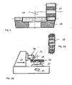
- Figure 5 shows a peripheral disk grinding wheel of the prior art as for instance described in EP 0 330 289 A1 .
- the grinding profile duplicates the face gear mating pinion tooth profile. This profile forms one point of the face gear profile on each side of the grinding wheel (one roll position and one face width position). If the wheel strokes in direction of the virtual pinion 48, one contact line (on each side of the generated profile) between virtual pinion 48 and face gear is formed. In order to form the entire face gear tooth profile, the grinding wheel has to rotate around the virtual pinion axis 49 (while it strokes). If the stroke motion was infinitely fast and if the rotation around the virtual pinion axis was infinitely slow, then a mathematically perfect pair of face gear flanks would be generated.
- the grinding wheel position in Figure 5 represents a center roll position in the generating roll process.
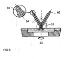
- Figure 6 shows a 2-dimensional cross sectional view of the face gear (face gear axis lies in cross section plane and the cross section plane is perpendicular to virtual pinion axis). The view is also directed at the periphery of the grinding wheel, which is shown not in the center roll position as in Figure 5 but in the start and end roll position 62/64.
- a tool disk e.g. cutting or grinding
- cutting blades or abrasive material
- Figure 7 shows the grinding (or cutting) disk in the bottom 72 (start), center 74 and top 76 (end) roll position.
- the disk has an abrasive layer (or cutting edges) on the left face, which is perpendicular to the axis of rotation (or slightly tapered) and on the outside.
- the face of the disk is a generating plane 77 which in the center roll position 74 perfectly represents the pitch line of the virtual pinion.
- the tool disk has to be rotated into every new roll position around the virtual pinion axis by an angle, calculated from the number of face gear teeth divided by the number of virtual pinion teeth, multiplied by the incremental work gear rotation angle, plus a small additional amount of rotation, which places the disk such that it has a common line with the involute in this particular roll position.
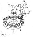
- Figure 9 shows a 3-dimensional view of the face gear and the tool disk.
- the tool disk is only represented with an outline in the bottom 72, center 74 and top 76 roll position.
- the discussed generating plane is the surface inside of the tool disk outline.
- the virtual pinion axis can be located in a virtual or theoretical bevel gear generating basic machine, such as is described in U.S. Patents Nos. 4,981,402 or 6,712,566 , in order to represent a generating cylindrical pinion (generating pinion) where the generating pinion and the work gear resemble the same relationship as the face gear and its mating cylindrical pinion in their final application (for example, a gear box). While the cutter rotates around the virtual pinion axis, the work has to rotate around its axis according to the ratio between pinion and face gear.
- the involute curvature radius can be calculated in a number of points along the generating pinion profile.
- the second order coefficient Ra 2 will basically define the curvature of the involute at the pitch point.
- the third order coefficient Ra 3 will take a constant change of curvature, between root and top into account.
- the largest part of the non-constant involute curvature change can be accomplished by defiling the fourth order coefficient Ra 4 .
- a preferred method of calculating optimal coefficient is to use a regression calculation, which, for example, applies the "least squared error method" to minimize the differences between the correct involute and the affect of the coefficients to roll motions, in order to simulate the involute shape by non-linear roll ratio. Higher orders than 4 can be applied to improve the involute accuracy, or the mathematical function of the involute can be applied directly in the machine kinematics.
- An example of a computation of the correction amount between straight line and involute 80 is shown in Figure 8 .
- Figure 8 shows to the left in a 2-dimensional graphic, a view at the tool disk, which also shows the position of the virtual pinion axis 49 and three contact lines, representing the bottom 72, center 74 and top roll 76 position.
- the view onto the periphery of the tool disk is shown in the center roll position 74.
- the contact lines are shown in this view as points.
- the correct involute 80 of the virtual pinion is drawn inside of the disk where the involute 80 contacts the generating plane 77 in the contact point (contact line) of the center roll position).
- the involute function can be calculated with the virtual pinion information such as pressure angle and pitch diameter.
- the points on the disk's generating surface can be connected with the involute with circles which have their origin in the point which represents the location of the virtual pinion axis. Only at the pitch point (center roll position) will the arc length be zero. The arc in every other position represents the precise value of the small additional amount of rotation (angle ⁇ ), either to be used to define modified roll coefficients (Equation 1) or to be superimposed on the tool disk rotation around the virtual pinion axis during the generating roll. It is also possible to give the outside profile exactly the shape of the involute instead of a straight line, perpendicular to the tool axis. In this case, no corrective rotation has to be applied.
- the tool is fed to full slot depth in the work piece by a suitable tool feeding method, such as by vector feeding, for example, as shown in U.S. Patents Nos. 5,310,295 or 5,716,174 .
- the angular orientation of the tool feed process portion (plunging) is preferably chosen to be the root roll position. After the tool tip reaches the slot bottom, the generating roll begins, which forms the face gear tooth flank profile, beginning at the root and ending at the top of the face gear tooth ( Figure 7 ).
- the tool may be positioned in the top roll position after indexing and the face gear flank profile may be generated from the top down to the root without any plunging.
- the tool can be repositioned in the virtual bevel gear generating basic machine, such that it represents the second flank of the generating pinion.
- the same procedure used to generate the first flank can be applied.
- the slots already exist from the first flank generating thereby allowing the application of finishing parameters regarding surface speed and roll motion.
- the first slot cutting is effectively a roughing-finishing combination.
- the feed motion in order to move the tool from the indexing position to the bottom roll position 72 can occur fast (rapid feed) along a substantial amount of the distance (90% for example) and slow down at the end of the feed, when only a small amount of material is removed before the generating roll begins.
- Figures 10A and 10B show the triangular vector diagram, which correlates with its coordinate system and vectors directly to a cradle style bevel gear generator.
- Figure 10B represents the front view, perpendicular to the cradle axis (equal to the virtual pinion axis 49).
- R M points from the cradle axis to the root of the generated face gear slot.
- E X points from the cradle axis to the tool disk origin (tool axis reference point).
- Y cut is the tool disk axis vector.
- R W points from the tool disk center 108 to the root of the generated face gear slot.
- the center of roll position is shown where Y cut has an angle of equal to the virtual pinion's pressure angle but lies in the plane X-Z with no other inclinations.
- Figure 10A shows the top view of the triangular vector diagram. This view verifies the vector arrangement from the top view and delivers, together with the front view, a single valued definition of the vector diagram.
- first and second flank cutting will translate the first and second flank cutting into an upper and lower cutting position within the free form machine.
- first flanks e.g. upper flanks
- second flank e.g. lower flanks
- the tool curvature defined by the circumferential tool (e.g. cutter) radius, which will generate a root line which is not straight but curved.
- the slot depth at the ends of the face gear teeth is correct (derived from the face gear mating cylindrical pinion plus clearance) but has excess depth between toe and heel and is commonly the deepest at mid face.
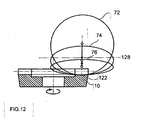
- Figure 12 shows how the deepest root line of the face gear 10 is formed by the periphery of the tool disk.
- the resulting root line will 122 be the enveloping surface from the spectrum of roll positions.
- the inner and the outer end of the face gear have the theoretical depth (of the theoretically parallel deep tooth as shown on the left side of the face gear).
- the curvature of the root line 122 may be controlled with the diameter of the cutter disk, however, the curved root line 122 has not shown disadvantages in straight bevel gears manufactured In accordance with US 7,364,391 mentioned above. Thus, it is a preferred embodiment to use the largest possible cutter disk for a given design.
- the cutter disk only forms a rotational symmetric surface on its axial face. This allows the approximation of involutes of spur pinion flanks.
- the flanks of helical gears wind around the pinion base cylinder like a spiral. The spiral shape cannot be approximated using a rotating cutting disk, which limits the inventive method to face gears that use a spur pinion as a mating member.
- Helical gears with a very small helix angle e.g. below 5°
Landscapes
- Engineering & Computer Science (AREA)
- Mechanical Engineering (AREA)
- Gear Processing (AREA)
- Gears, Cams (AREA)
Description
- The present invention is directed to the manufacturing of gears and in particular, to a method and tool for manufacturing face gears.
- Face gears are ring gears with a face angle (and root angle) equal to the shaft angle between the face gear and it's mating member. The mating member is a regular cylindrical spur or helical pinion. Standard face gears have a face angle of 90° which corresponds to a shaft angle of also 90° (such 90° gears are also known as "crown" gears).
- To date, methods of manufacturing face gears have been complicated, with special tools dedicated to a single design applied on machine tools which are usually modified cylindrical gear manufacturing machines. Such methods for the soft manufacturing of face gears include:
- Hobbling, using a job dedicated special hob on a cylindrical hobbing machine, which is modified in order to allow for cutting at the lowest circumferential section of the hobbing tool (vertical hobbing machine table axis).
- Shaping, using a shaper cutter representing the mating cylindrical pinion, and a shaping machine, with a work table which is rotated (versus a regular cylindrical gear shaping machine) by the face gear set's root angle (commonly 90°).
- Universal milling method, using an end mill on a 5-axes machining center.
- Grinding from solid, using the grinding methods mentioned in the hard finishing section below.
- Today's known methods for the hard finishing of face gears include:
- Continuous grinding, using a threaded grinding wheel with a thread reference profile, identical to the face gear set's pinion tooth profile on a large diameter wheel with small width having generally 1.5 to 2.5 thread revolutions (see
WO 98/02268 US 6,390,894 ; andUS 6,951,501 ). - Single index generating grinding with a wheel profile identical to the face gear set's pinion tooth profile.
- Skiving, using a shaper cutter or special hob.
- Skiving, using and end mill on a 5-axes machining center.
- Honing, using a modified pinion with an abrasive layer on the tooth surface.
- Presently, face gear soft machining methods depend on job specific, special tools, which are expensive and not flexible regarding their use for other jobs or for optimizations. The machining time of a face gear is in general significantly longer than the cutting time of a comparable cylindrical or bevel ring gear.
- Two of the more common face gear hard finishing methods use either a very complex tool geometry which is difficult to dress and requires a long dressing time (threaded wheel grinding), or a complicated and time consuming generating roll, combined with a feed motion in face width direction (single index generating grinding).
- Skiving with a special hob or a shaper cutter made from carbide material provides reasonable cutting times but requires a tool which is not only expensive but also not readily available or not available at all.
- Face gear honing requires, for example, a heat treated, ground and CBN coated pinion, which is expensive, not flexible and depends on a rather large pinion offset (equal the required offset between face gear and mating cylindrical pinion) for good chip removal, which limits the application to face gear sets which have such a high offset.
- The present invention is directed to a cutter disk having cutting blades oriented on its circumference with the cutting edges of the blades oriented perpendicular to the axis of rotation of the cutter disk thereby representing a plane which can be oriented to a work piece (e.g. face gear) under an angle equal to the pressure angle of the mating face gear set's pinion, and, which can be rotated around a virtual pinion axis to generate a tooth flank on the work piece.
-
-
Figure 1 shows a 2-dimensional, cross sectional view of a face gear and its mating cylindrical spur pinion. -
Figures 2A and 2B show, respectively, a spherical hobbing tool and a cylindrical hobbing machine. -
Figure 3 shows a face gear, where the pinion inFigure 1 is replaced with a shaper cutter. -
Figure 4 shows a 3-dimensional view of a threaded grinding wheel which is dressed such that it duplicates in an axial plane cross section the profile of the hobbing tool ofFigure 2A . -
Figure 5 shows a peripheral disk grinding wheel with a grinding profile that duplicates the face gear mating pinion tooth profile. -
Figure 6 shows a 2-dimensional cross sectional view of a face gear and grinding wheel (face gear axis lies in cross section plane, cross section plane is perpendicular to virtual pinion axis).Figure 6 also contains an exploded view of the periphery of the grinding wheel. -
Figure 7 shows the grinding (or cutting) disk in the bottom (start), center and top (end) roll position. -
Figure 8 shows a 2-dimensional graphic (left) and a view at the tool disk (right), which also shows the position of the virtual pinion axis and three contact lines representing the bottom, center and top roll positions. -
Figure 9 shows a 3-dimensional view of the face gear and the tool disk. The tool disk is represented with an outline in the bottom, center and top roll positions. -
Figures 10A and 10B show, respectively, front and top views of the triangular vector diagram which correlate with its coordinate system and vectors directly to a cradle style bevel gear generator. -
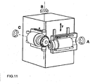
Figure 11 shows the arrangement between cutter disk and face gear in a 6-axis free form machine. -
Figure 12 shows how the deepest root line of the face gear is formed by the periphery of the tool disk. - Before any features and at least one construction of the invention are explained in detail, it is to be understood that the invention is ,not limited in its application to the details of construction and the arrangements of the components set forth in the following description or illustrated in the drawings. The invention is capable of other constructions and of being practiced or being carried out in various ways.
- The utilization of face gears for certain applications is highly dependent on the availability of an efficient and economical manufacturing process. To date, no economical soft machining or hard finishing process for face gears is available.
-
Figure 1 shows a 2-dimensional, cross sectional view of aface gear 10 and its matingcylindrical spur pinion 12. Theshaft angle 14 between face gear axis and pinion axis is 90° in this example. Shaft angles larger than 90° will make the face gear an internal ring gear. In the special case of a 0° shaft angle, the face gear pair mutates to a cylindrical ring gear. -
Figure 2A shows aspherical hobbing tool 20. The cutting blades (cutting teeth) of the hob represent the teeth of a spur pinion, as they are grouped around the cylindrical pinion body (in a section consisting of 3 teeth).Figure 2B also shows a cylindrical hobbing machine with a modifiedhob head 26, which allows to cut the teeth of a face gear on the bottom section of the hob. Commonly a single start hob is used which will require awork rotation 23 of one pitch for every revolution of the hob. The hob is fed from the outside of theface gear 10 to the inside. During the tool feeding, a compensation amount of the work rotation, depending on the tool lead angle has to be considered. -
Figure 3 shows a face gear where thepinion 12 inFigure 1 is replaced by ashaper cutter 30. The shaper cutter has a number of cutting teeth, equal to the mating pinion (also equal virtual pinion) of theface gear 10. The cutting contour in a plane, perpendicular to the shaper cutter axis duplicates exactly the virtual pinion's face contour. While the shaper cutter rotates in mesh with the face gear, astroke motion 37 in axial cutter direction is required for the chip removing action. -
Figure 4 shows a 3-dimensional view of a threaded grinding wheel which is dressed such that it duplicates in an axial plane cross section the profile of the hobbing tool ofFigure 1 . While the threaded wheel rotates (41), the curved orientation of the grinding thread profiles approximate the rotatingvirtual pinion 48 profile at the location of the plane, defined by the grinding wheel axis and the stroke direction. In order to simulate the entire width of the virtual pinion, the grinding wheel has to traverse (47) in thevirtual pinion axis 49 direction along the face width of the face gear. In case of a single thread grinding wheel, the work has to rotate one pitch for every wheel rotation. During the traversing process, the work rotation is superimposed by a lead compensation value. -
Figure 5 shows a peripheral disk grinding wheel of the prior art as for instance described inEP 0 330 289 A1 . The grinding profile duplicates the face gear mating pinion tooth profile. This profile forms one point of the face gear profile on each side of the grinding wheel (one roll position and one face width position). If the wheel strokes in direction of thevirtual pinion 48, one contact line (on each side of the generated profile) betweenvirtual pinion 48 and face gear is formed. In order to form the entire face gear tooth profile, the grinding wheel has to rotate around the virtual pinion axis 49 (while it strokes). If the stroke motion was infinitely fast and if the rotation around the virtual pinion axis was infinitely slow, then a mathematically perfect pair of face gear flanks would be generated. The grinding wheel position inFigure 5 represents a center roll position in the generating roll process. -
Figure 6 shows a 2-dimensional cross sectional view of the face gear (face gear axis lies in cross section plane and the cross section plane is perpendicular to virtual pinion axis). The view is also directed at the periphery of the grinding wheel, which is shown not in the center roll position as inFigure 5 but in the start and endroll position 62/64. - As discussed above, the identified prior art soft and hard machining methods for face gears depend on job specific, complex and special tools which are expensive and inflexible regarding their use for other jobs or for optimizations. Additionally, processing and/or dressing times are long and complicated.
- The inventor has discovered that a tool disk (e.g. cutting or grinding) having cutting blades (or abrasive material) oriented on its circumference with the cutting edges of the blades oriented perpendicular to the axis of rotation of the cutter disk, represents a plane which can be oriented to a work piece (face gear) under an angle equal to the pressure angle of the mating face gear set's pinion and which can be rotated around a virtual pinion axis, while it generates one face gear flank on the work piece.
Figure 7 shows the grinding (or cutting) disk in the bottom 72 (start),center 74 and top 76 (end) roll position. The disk has an abrasive layer (or cutting edges) on the left face, which is perpendicular to the axis of rotation (or slightly tapered) and on the outside. The face of the disk is a generatingplane 77 which in thecenter roll position 74 perfectly represents the pitch line of the virtual pinion. In every roll position between start and end roll, the tool and the work piece have to be rotated about a certain angles. The tool disk has to be rotated into every new roll position around the virtual pinion axis by an angle, calculated from the number of face gear teeth divided by the number of virtual pinion teeth, multiplied by the incremental work gear rotation angle, plus a small additional amount of rotation, which places the disk such that it has a common line with the involute in this particular roll position. -
Figure 9 shows a 3-dimensional view of the face gear and the tool disk. The tool disk is only represented with an outline in the bottom 72,center 74 and top 76 roll position. The discussed generating plane is the surface inside of the tool disk outline. In case of the inventive process, there is no traversing feed motion, which will significantly reduce the machining time compared to processes which require the traversing feed motion. - The virtual pinion axis can be located in a virtual or theoretical bevel gear generating basic machine, such as is described in
U.S. Patents Nos. 4,981,402 or6,712,566 , in order to represent a generating cylindrical pinion (generating pinion) where the generating pinion and the work gear resemble the same relationship as the face gear and its mating cylindrical pinion in their final application (for example, a gear box). While the cutter rotates around the virtual pinion axis, the work has to rotate around its axis according to the ratio between pinion and face gear. - Since the cutter blades represent one flank of a straight sided rack, as mentioned above, it is not yet duplicating a correct generating involute of the pinion flank (
Figure 7 , generating involute versus generating plane). This can be achieved by shaping the cutting edge of the blade identical to the involute of the original pinion flank which should mate with the face gear flank to be manufactured. Another possibility which allows the use of the simplistic and universal straight edged cutting tools is the introduction of a non-constant generating roll relationship (for example, Modified Roll) while generating one flank or utilizing one or more active machine settings such as described inU.S. Patent No. 5,580,298 . Roll angle related coefficients of 4 orders or higher are multiplied with the constant basic ratio of roll between generating pinion and work gear (face gear) which will accomplish a good approximation of the involute of a virtual generating pinion.
Where: - Ra... ratio of roll (not constant)
- q... roll angle distance from center of roll
- Ra0... basic ratio of roll (constant)
- Ra1 ... first order coefficient, multiplied with roll angle distance from center of roll
- Ra2... second order coefficient, multiplied with square of roll angle distance from center of roll
- Ra3... third order coefficient, multiplied with third power of roll angle distance from center of roll
- Ra4... fourth order coefficient, multiplied with fourth power of roll angle distance from center of roll
- The involute curvature radius can be calculated in a number of points along the generating pinion profile. The second order coefficient Ra2 will basically define the curvature of the involute at the pitch point. The third order coefficient Ra3 will take a constant change of curvature, between root and top into account. The largest part of the non-constant involute curvature change can be accomplished by defiling the fourth order coefficient Ra4. A preferred method of calculating optimal coefficient is to use a regression calculation, which, for example, applies the "least squared error method" to minimize the differences between the correct involute and the affect of the coefficients to roll motions, in order to simulate the involute shape by non-linear roll ratio. Higher orders than 4 can be applied to improve the involute accuracy, or the mathematical function of the involute can be applied directly in the machine kinematics. An example of a computation of the correction amount between straight line and
involute 80 is shown inFigure 8 . -
Figure 8 shows to the left in a 2-dimensional graphic, a view at the tool disk, which also shows the position of thevirtual pinion axis 49 and three contact lines, representing the bottom 72,center 74 andtop roll 76 position. On the right side the view onto the periphery of the tool disk is shown in thecenter roll position 74. The contact lines are shown in this view as points. Thecorrect involute 80 of the virtual pinion is drawn inside of the disk where the involute 80 contacts the generatingplane 77 in the contact point (contact line) of the center roll position). The involute function can be calculated with the virtual pinion information such as pressure angle and pitch diameter. The points on the disk's generating surface can be connected with the involute with circles which have their origin in the point which represents the location of the virtual pinion axis. Only at the pitch point (center roll position) will the arc length be zero. The arc in every other position represents the precise value of the small additional amount of rotation (angle Δϕ), either to be used to define modified roll coefficients (Equation 1) or to be superimposed on the tool disk rotation around the virtual pinion axis during the generating roll. It is also possible to give the outside profile exactly the shape of the involute instead of a straight line, perpendicular to the tool axis. In this case, no corrective rotation has to be applied. - In the case where wheel diameters are small relative to the face width, a slightly distorted generating profile may result. In other words, only at the center of the face width will the involute on the tool be perpendicular to the theoretical root line. However, if the face width is smaller than 2•sin5°•(Diameter/2), then the profile miss-location in profile direction amounts to (1-cos5°)•Diameter/2, which is 0.38% of the tool disk radius, which can be neglected in most cases. The Δϕ angles (for any desired number of profile points) can be used as the heretofore mentioned small additional amount of rotation of the virtual pinion (in the case of a plane too disk).
- While the described procedure will only generate one flank of one slot, it has to be repeated for every slot of the face gear according to the face gear's tooth count (single indexing process). In order to achieve this, the tool is withdrawn from the face gear slot to an indexing position, then the indexing rotation of the work gear (face gear) occurs.

- After indexing, the tool is fed to full slot depth in the work piece by a suitable tool feeding method, such as by vector feeding, for example, as shown in
U.S. Patents Nos. 5,310,295 or5,716,174 . The angular orientation of the tool feed process portion (plunging) is preferably chosen to be the root roll position. After the tool tip reaches the slot bottom, the generating roll begins, which forms the face gear tooth flank profile, beginning at the root and ending at the top of the face gear tooth (Figure 7 ). - Alternatively, the tool may be positioned in the top roll position after indexing and the face gear flank profile may be generated from the top down to the root without any plunging.
- After the first flank of every slot is generated, the tool can be repositioned in the virtual bevel gear generating basic machine, such that it represents the second flank of the generating pinion. In order to generate the second flank of every face gear tooth, the same procedure used to generate the first flank can be applied. For the cutting process of the second flanks, the slots already exist from the first flank generating thereby allowing the application of finishing parameters regarding surface speed and roll motion. In contrast to this, the first slot cutting is effectively a roughing-finishing combination.
- If the generating occurs from root to top, then the feed motion in order to move the tool from the indexing position to the
bottom roll position 72 can occur fast (rapid feed) along a substantial amount of the distance (90% for example) and slow down at the end of the feed, when only a small amount of material is removed before the generating roll begins. - The inventive set up and kinematic relationships can be based on a virtual bevel gear generating basic machine as described above or on other models or procedures, which are applicable as well.
Figures 10A and 10B show the triangular vector diagram, which correlates with its coordinate system and vectors directly to a cradle style bevel gear generator.Figure 10B represents the front view, perpendicular to the cradle axis (equal to the virtual pinion axis 49). RM points from the cradle axis to the root of the generated face gear slot. EX points from the cradle axis to the tool disk origin (tool axis reference point). Ycut is the tool disk axis vector. RW points from thetool disk center 108 to the root of the generated face gear slot. The center of roll position is shown where Ycut has an angle of equal to the virtual pinion's pressure angle but lies in the plane X-Z with no other inclinations.Figure 10A shows the top view of the triangular vector diagram. This view verifies the vector arrangement from the top view and delivers, together with the front view, a single valued definition of the vector diagram. - From the virtual basic machine it is possible to transform the face gear cutting process into suitable mechanical machines settings. It is also possible as a preferred embodiment of the inventive process to transform the virtual basic machine (or any other model) into a table of axis positions and/or motions of a free form 5 or 6-axes machine such as shown in
Figure 11 (for example,U.S. Patents Nos. 4,981,402 or6,712,566 ).Figure 11 shows the arrangement between cutter disk and face gear in a 6-axis free form machine. The vector diagrams inFigures 10A and 10B , plus the generating roll ratio represent all information in order to calculate an axes position table. The artisan will understand that small additional amounts of rotation Δϕ have to be superimposed to the tool rotation in order to produce correct flank forms. - The transformation of virtual basic settings into the positions (and/or motions) of a rectilinear free form machine will translate the first and second flank cutting into an upper and lower cutting position within the free form machine. In case of a true face gear, with a face and pitch angle of 90° the work is required to rotate 180° after first flanks (e.g. upper flanks) are generated in order to generate the second flank (e.g. lower flanks) of the same slots with the correct slot width.
- In face gears with face and pitch angles not equal 90° (in case of shaft angles between cylindrical pinion and face gear of unequal 90°) a calculation such as shown in
U.S. Patent No. 7,364,391 , hereby incorporated by reference, may be applied in order to find the work phase angle rotation required to generate the correct slot width. - In the inventive process, consideration should be given to the tool curvature, defined by the circumferential tool (e.g. cutter) radius, which will generate a root line which is not straight but curved. The slot depth at the ends of the face gear teeth is correct (derived from the face gear mating cylindrical pinion plus clearance) but has excess depth between toe and heel and is commonly the deepest at mid face.
Figure 12 shows how the deepest root line of theface gear 10 is formed by the periphery of the tool disk. The resulting root line will 122 be the enveloping surface from the spectrum of roll positions. The inner and the outer end of the face gear have the theoretical depth (of the theoretically parallel deep tooth as shown on the left side of the face gear). Between the two ends an excess depth is generated, which generally is the deepest at midface. The curvature of theroot line 122 may be controlled with the diameter of the cutter disk, however, thecurved root line 122 has not shown disadvantages in straight bevel gears manufactured In accordance withUS 7,364,391 mentioned above. Thus, it is a preferred embodiment to use the largest possible cutter disk for a given design. - Another aspect of the inventive method is that the cutter disk only forms a rotational symmetric surface on its axial face. This allows the approximation of involutes of spur pinion flanks. The flanks of helical gears wind around the pinion base cylinder like a spiral. The spiral shape cannot be approximated using a rotating cutting disk, which limits the inventive method to face gears that use a spur pinion as a mating member. Helical gears with a very small helix angle (e.g. below 5°) will only show minor flank and root deviations, which can be at least partially corrected.
- Shaft angles between
face gear 10 and mating pinion between 0° (face gear mutates into a cylindrical gear) and above 90° (face gear becomes an internal ring gear) are possible with the inventive method. Also shaft offset between face gear and mating pinion can be realized with the inventive method. - While the invention has been described with reference to preferred embodiments it is to be understood that the invention is not limited to the particulars thereof. The present invention is intended to include modifications which would be apparent to those skilled in the art to which the subject matter pertains without deviating from the scope of the appended claims.
- In the following, the reference numerals of the figures are explained.
-
Fig 1 (cross-section of face gear set):- 10
- face gear
- 12
- cylindrical spur pinion
- 14
- shaft angle (= 90°)
-
Fig.2a :- 20
- spherical hobbing tool
-
Fig. 2b (face gear hobbing):- 10
- face gear
- 21
- hob rotation
- 22
- work head table
- 24
- special spherical face gear hob
- 26
- modified hob head
- 27
- feed direction
-
Fig. 3 (face gear shaping).- 10
- face gear
- 14
- shaft angle (= 90°)
- 30
- shaper cutter
- 31
- generating roll rotation of tool
- 33
- generating roll rotation of work
- 37
- cutting motion
-
Fig. 4 (threaded wheel grinding of a face gear):- 41
- grinding wheel rotation
- 43
- continuous indexing rotation of work with feed compensation
- 47
- traversing feed motion
- 48
- virtual pinion
- 49
- virtual pinion axis
-
Fig. 5 (single index generating grinding- 31
- generating roll rotation of tool
- 33
- generating roll rotation of work
- 41
- grinding wheel rotation
- 47
- traversing feed motion
- 48
- virtual pinion
- 49
- virtual pinion axis
- 51
- wheel axis
-
Fig. 6 (single index generating grinding):- 31
- generating roll rotation of tool
- 33
- generating roll rotation of work
- 60
- involute
- 62
- grinding wheel in start roll position
- 64
- grinding wheel in end roll position
-
Fig. 7 (face gear flank generating with tool disk):- 31
- generating roll rotation of tool
- 33
- generating roll rotation of work
- 70
- generating involute
- 71
- tool rotation
- 72
- bottom roll position
- 73
- tool axis
- 74
- center roll position
- 75
- cutting tool plane
- 76
- top roll position
- 77
- generating plane
-
Fig. 8 (determination of correction amount):- 49
- virtual pinion axis
- 72
- bottom roll position
- 73
- tool axis
- 74
- center roll position
- 76
- top roll position
- 77
- generating plane
- 80
- correct involute
- 88
- virtual pinion center
-
Fig. 9 (determination of correction amount):- 31
- generating roll rotation of tool
- 33
- generating roll rotation of work
- 71
- tool rotation
- 72
- bottom roll position
- 74
- center roll position
- 76
- top roll position
- 90
- cutting blade planes
-
Fig. 10a front view of basic machine configuration):- 10
- face gear
- 49
- virtual pinion axis
- 101
- work gear axis
- 103
- generating gear axis
-
Fig. 10b (top view of basic machine configuration):- 10
- face gear
- 101
- work gear axis
- 103
- generating gear axis
- 106
- tool tip circle
- 108
- tool disk center
-
Fig. 11 (free form cutting or grinding machine):- Rotational axes
- A, B, C
- Linear axes
- y, z
-
Fig. 12 (generating of curved root line):- 10
- face gear
- 72
- bottom roll position
- 74
- center roll position
- 76
- top roll position
- 122
- curved root line
- 128
- pinion axis
Claims (11)
- A method of manufacturing a face gear (10), said face gear having a plurality of tooth slots with each tooth slot comprising first and second tooth surfaces, said method comprising:providing a face gear workpiece having an axis of rotation (101);providing a disk-shaped tool having a circumference and an axis of rotation (51), said tool having one or more stock removing surface(s) positioned on the circumference with the stock-removing surfaces being oriented generally perpendicular to said axis of rotation of said disc-shaped tool and defining a generating plane (77),positioning said tool and said workpiece relative to one another for generating one of said first or second tooth surfaces on said workpiece;rotating said tool about said axis of rotation and feeding (47) said tool relatively into said face gear workpiece;generating one of said first or second tooth surfaces on said workpiece by moving the tool and workpiece relative to each other;wherein said generating comprises rotating said work piece about its axis of rotation and rotating said tool about an axis of rotation (49) of a virtual pinion (48) in mesh with said face gear workpiece, said tool and generating plane describing a generating roll (31, 33) which emulates the rolling motion of a tooth of said virtual pinion rotating in mesh with said face gear workpiece during said generating.
- The method of claim 1 further comprising repositioning said tool and said workpiece relative to one another and generating the other of said first or second tooth surfaces on said workpiece, said generating comprises rotating said work piece about its axis of rotation and rotating said tool about an axis of rotation (49) of a virtual pinion (48) in mesh with said face gear workpiece, said tool and generating plane describing a generating roll which emulates the rolling motion of a tooth of said virtual pinion rotating in mesh with said face gear workpiece during said generating.
- The method of claim 1 wherein said rotation of the tool about the pinion axis of rotation and said rotation of said face gear workpiece are carried out in a timed relationship with one another.
- The method of claim 3 wherein said timed relationship is in accordance with the number to teeth of the face gear and the number of teeth of the virtual pinion (48).
- The method of claim 1 wherein said generating roll comprises a predetermined number of generating roll Increments and wherein said face gear workpiece is rotated by an additional predetermined amount during each of said increments so as to position the tool to have a common line with the tooth surface being formed at the particular generating roll increment.
- The method of claim 1 wherein said one or more stock removing surfaces of said tool are straight.
- The method of claim 1 wherein said one or more stock removing surfaces of said tool are of a shape matching the tooth flank shape of the virtual pinion (48).
- The method of claim 1 wherein the virtual pinion comprises tooth flank surfaces in the form of an involute.
- The method of claim 1 wherein subsequent to generating a tooth flank surface, the tool is withdrawn from a tooth slot and the face gear workpiece is indexed to another slot position and the generating method is repeated for that tooth slot position, the steps of withdrawing, indexing and generating being repeated for all tooth slots on said face gear workpiece.
- The method of claim 1 wherein said feeding comprises plunging said tool to a tooth bottom position in said face gear work piece followed by generating a tooth surface by said generating roll along a generating path beginning at the bottom position of said tooth and commencing in direction toward a top portion of said tooth.
- The method of claim 1 wherein said feeding comprises contacting said tooth at a top portion thereof followed by generating a tooth surface by said generating roll along a generating path beginning at the top portion of said tooth and commencing in direction toward a tooth bottom position of said tooth.
Applications Claiming Priority (2)
| Application Number | Priority Date | Filing Date | Title |
|---|---|---|---|
| US23078509P | 2009-08-03 | 2009-08-03 | |
| PCT/US2010/044215 WO2011017301A1 (en) | 2009-08-03 | 2010-08-03 | Method and tool for manufaturing face gears |
Publications (2)
| Publication Number | Publication Date |
|---|---|
| EP2461932A1 EP2461932A1 (en) | 2012-06-13 |
| EP2461932B1 true EP2461932B1 (en) | 2014-09-17 |
Family
ID=42751705
Family Applications (1)
| Application Number | Title | Priority Date | Filing Date |
|---|---|---|---|
| EP10742384.0A Active EP2461932B1 (en) | 2009-08-03 | 2010-08-03 | Method and tool for manufacturing face gears |
Country Status (8)
| Country | Link |
|---|---|
| US (1) | US9108258B2 (en) |
| EP (1) | EP2461932B1 (en) |
| JP (1) | JP5700854B2 (en) |
| KR (1) | KR20120040251A (en) |
| CN (1) | CN102470466B (en) |
| BR (1) | BR112012002408A2 (en) |
| RU (1) | RU2542040C2 (en) |
| WO (1) | WO2011017301A1 (en) |
Cited By (1)
| Publication number | Priority date | Publication date | Assignee | Title |
|---|---|---|---|---|
| CN106238830A (en) * | 2016-08-29 | 2016-12-21 | 西北工业大学 | A kind of processing method with bowl-shape disc milling cutter milling face gear |
Families Citing this family (34)
| Publication number | Priority date | Publication date | Assignee | Title |
|---|---|---|---|---|
| PL217474B1 (en) * | 2010-05-28 | 2014-07-31 | Igor Zarębski | Gear generating method for not straight gears |
| DE102010023728A1 (en) * | 2010-06-14 | 2011-12-15 | Liebherr-Verzahntechnik Gmbh | Method of manufacturing a plurality of identical gears by means of machining |
| DE102010039491A1 (en) * | 2010-08-18 | 2012-02-23 | Deckel Maho Pfronten Gmbh | Method and device for generating control data for forming a tooth flank by milling machining of a workpiece on a machine tool |
| DE202011050054U1 (en) * | 2011-05-06 | 2011-09-15 | Klingelnberg Ag | Skiving tool with knife bars |
| JP5748582B2 (en) | 2011-07-12 | 2015-07-15 | 三菱重工業株式会社 | Threaded tool manufacturing method |
| CN102407389A (en) * | 2011-10-10 | 2012-04-11 | 唐进元 | Face-gear numerical-control gear-grinding machine tool |
| CN102756132A (en) * | 2012-06-19 | 2012-10-31 | 徐州丰禾回转支承制造有限公司 | Turning process for disc parts |
| EP2732895B1 (en) * | 2012-11-14 | 2015-10-21 | Burri Werkzeugmaschinen GmbH & Co. KG | Machine tool for manufacturing profiles |
| DE102012022439A1 (en) * | 2012-11-16 | 2014-05-22 | Marcel Sobczyk | Method for determining the free surface contour of a Wälzschälwerkzeuges, Wälzschälwerkzeug and its use |
| EP2792442B1 (en) | 2013-04-17 | 2018-08-22 | Klingelnberg AG | Skiving tool for skiving teeth on a face gear |
| CN103331494B (en) * | 2013-07-10 | 2015-10-28 | 上海第二工业大学 | A kind of concurrent aces variable tooth thickness gear profile error analytical method |
| SE1350983A1 (en) * | 2013-08-27 | 2015-02-28 | Sandvik Intellectual Property | Tools and cutters for shell milling |
| CN103692026B (en) * | 2014-01-16 | 2017-01-11 | 哈尔滨理工大学 | Orthogonal face gear grinding method based on planar grinding wheel end face |
| CA2935533C (en) * | 2014-05-30 | 2018-07-24 | Mitsubishi Heavy Industries Machine Tool Co., Ltd. | Cutter for skiving |
| US9623502B2 (en) * | 2014-11-07 | 2017-04-18 | Jtekt Corporation | Gear machining device and gear machining method |
| DE102015008964A1 (en) * | 2015-07-10 | 2017-01-12 | Liebherr-Verzahntechnik Gmbh | Method for dressing a tool |
| DE102015008956A1 (en) * | 2015-07-10 | 2017-01-12 | Liebherr-Verzahntechnik Gmbh | Method for producing a toothed workpiece with a modified surface geometry |
| DE102015009017A1 (en) * | 2015-07-10 | 2017-01-12 | Liebherr-Verzahntechnik Gmbh | Method for producing a toothed workpiece with a modified surface geometry |
| CN105196014B (en) * | 2015-10-13 | 2017-05-24 | 中南大学 | Face gear machining method based on linear cutting |
| DE102016005257A1 (en) * | 2016-04-28 | 2017-11-02 | Liebherr-Verzahntechnik Gmbh | Process for tooth processing of a workpiece |
| CN106041226B (en) * | 2016-07-15 | 2018-12-11 | 湖北威能达传动有限责任公司 | A kind of end-face coupling fixture and its processing method |
| DE102016009468A1 (en) * | 2016-08-03 | 2018-02-08 | Audi Ag | Honing process with cross grinding for gears |
| JP7024303B2 (en) * | 2016-10-13 | 2022-02-24 | 株式会社ジェイテクト | Gear processing equipment and gear processing method |
| DE102016012915B4 (en) * | 2016-10-21 | 2018-07-26 | KAPP Werkzeugmaschinen GmbH | Wiper arm for grinding internally profiled workpieces with a grinding wheel |
| RU173681U1 (en) * | 2016-12-06 | 2017-09-05 | федеральное государственное бюджетное образовательное учреждение высшего образования "Белгородский государственный технологический университет им. В.Г. Шухова" | SHUTTER DENT MILLING MACHINE |
| DE102017000260A1 (en) * | 2017-01-12 | 2018-07-12 | Gleason-Pfauter Maschinenfabrik Gmbh | METHOD FOR THE HARDWARE PROCESSING OF CUTTING, IN PARTICULAR INSIDE AND MACHINE TOOLS SUITABLE THEREOF |
| JP7066983B2 (en) * | 2017-06-07 | 2022-05-16 | 株式会社ジェイテクト | Gear processing method and gear processing equipment |
| CN108188494A (en) * | 2017-12-22 | 2018-06-22 | 重庆文理学院 | A kind of milling cutter and method for processing face gear |
| CN107855614B (en) * | 2017-12-26 | 2023-04-07 | 吉林大学 | Gear honing machine tool without axial feeding and gear grinding method |
| JP6762588B1 (en) * | 2019-09-04 | 2020-09-30 | 九州精密工業株式会社 | Skying cutter |
| CN111515469B (en) * | 2020-04-07 | 2021-10-19 | 西安科技大学 | Machining method for manufacturing orthogonal straight-tooth face gear by disc-shaped cutter |
| DE102020002806A1 (en) | 2020-05-12 | 2021-11-18 | Balance Drive AG | Method for producing a crown gear, milling and / or grinding arrangement |
| CN114211057B (en) * | 2021-11-30 | 2023-09-26 | 西北工业大学 | Method for grinding non-orthogonal face gear based on cylindrical gear numerical control gear grinding machine |
| EP4197680A1 (en) * | 2021-12-17 | 2023-06-21 | Klingelnberg AG | Method for continuous grinding of internal toothings |
Family Cites Families (39)
| Publication number | Priority date | Publication date | Assignee | Title |
|---|---|---|---|---|
| US1365433A (en) * | 1918-03-14 | 1921-01-11 | Skf Svenska Kullagerfab Ab | Method of manufacturing bevel-gear wheels |
| US1385097A (en) * | 1918-12-10 | 1921-07-19 | Schmick Screw And Gear Company | Gear-making machine |
| US1403113A (en) * | 1919-02-25 | 1922-01-10 | Geffroy Jules Herve | Machine for cutting spiral bevel gears |
| US1863571A (en) * | 1925-02-12 | 1932-06-21 | H T Bradner | Machine and process for generating gears |
| US1676419A (en) * | 1925-06-22 | 1928-07-10 | Gleason Works | Method of and machine for producing gears |
| US1655080A (en) * | 1926-02-19 | 1928-01-03 | Gleason Works | Method of producing gears |
| US1673540A (en) * | 1926-05-10 | 1928-06-12 | Gleason Works | Method of producing hypoid gears |
| US1705887A (en) * | 1927-03-01 | 1929-03-19 | Gleason Works | Method of generating hypoid gears |
| US1934754A (en) * | 1931-03-23 | 1933-11-14 | Wildhaber Ernest | Method and means for forming gears |
| US2100705A (en) * | 1934-05-08 | 1937-11-30 | Gleason Works | Method of producing tapered gears |
| US2372240A (en) * | 1940-12-31 | 1945-03-27 | Gleason Works | Method of producing gears |
| FR930953A (en) | 1945-09-07 | 1948-02-10 | Gear wheel tooth flank grinding machine | |
| CH250712A (en) * | 1945-09-07 | 1947-09-15 | Buehler Hermann | Machine for grinding involute-shaped tooth flanks of gears with straight or angled teeth using the hobbing process. |
| DE1115104B (en) * | 1954-02-20 | 1961-10-12 | Oriental Gear Company Ltd | Method and device for producing a pair of spiral-toothed bevel gears |
| US3060642A (en) * | 1959-09-28 | 1962-10-30 | Parsons & Marine Eng Turbine | Means for generating involute gears |
| US3099939A (en) * | 1960-06-17 | 1963-08-06 | Gleason Works | Gear generating machine |
| DE2641554C3 (en) * | 1976-09-15 | 1981-06-25 | Maag-Zahnräder & -Maschinen AG, 8023 Zürich | Device for generating grinding of cylindrical gears |
| SU891272A1 (en) * | 1976-12-23 | 1981-12-23 | Предприятие П/Я М-5671 | Method of making gear-wheels |
| SU880244A3 (en) * | 1978-08-18 | 1981-11-07 | Мааг-Цанрэдер Унд-Машинен Аг (Фирма) | Method and lathe for grinding gear wheels |
| US4565474A (en) * | 1980-11-01 | 1986-01-21 | The Ingersoll Milling Machine Company | Method of generating involute tooth forms with a milling cutter |
| US4981402A (en) | 1987-08-24 | 1991-01-01 | The Gleason Works | Multi-axis bevel and hypoid gear generating machine |
| JPH01129020U (en) * | 1988-02-23 | 1989-09-04 | ||
| NL8800472A (en) * | 1988-02-24 | 1989-09-18 | Hankamp Bv | METHOD FOR MANUFACTURING AND / OR FINISHING CROWN WHEELS. |
| NL9002611A (en) * | 1990-11-29 | 1992-06-16 | Crown Gear Bv | TOOLS FOR MANUFACTURING CROWN WHEELS, AND METHOD FOR MANUFACTURING SUCH TOOLS. |
| US5175962A (en) * | 1991-09-05 | 1993-01-05 | The Gleason Works | Method of and apparatus for machining spur and helical gears |
| US5310295A (en) | 1993-03-22 | 1994-05-10 | The Gleason Works | Tool feeding method in gear manufacturing processes |
| NL9300617A (en) * | 1993-04-08 | 1994-11-01 | Crown Gear Bv | Method for manufacturing a crown wheel. |
| IT1272087B (en) * | 1993-12-17 | 1997-06-11 | Fiatavio Spa | METHOD AND MACHINE FOR THE CREATION OF TOOTHED WHEELS. |
| US5580298A (en) | 1994-09-27 | 1996-12-03 | The Gleason Works | Method of producing tooth flank surface modifications |
| US5823857A (en) * | 1996-04-23 | 1998-10-20 | Mcdonnell Douglas Helicopter Company | Apparatus and method for precision grinding of face gears |
| US5716174A (en) | 1996-08-29 | 1998-02-10 | The Gleason Works | Tool feeding method |
| US6390894B1 (en) | 1998-12-21 | 2002-05-21 | Derlan Aerospace Canada | Face gear manufacturing method and apparatus |
| JP2002011615A (en) * | 2000-06-26 | 2002-01-15 | Kawasaki Heavy Ind Ltd | Manufacturing method and machining device for face gear wheel |
| US6602115B2 (en) * | 2001-01-03 | 2003-08-05 | The Boeing Company | Tool and method for precision grinding of a conical face gear that meshes with a conical involute pinion |
| US6669415B2 (en) | 2001-02-16 | 2003-12-30 | The Gleason Works | Machine for producing bevel gears |
| RU2275277C1 (en) * | 2004-11-24 | 2006-04-27 | Федеральное государственное унитарное предприятие Всероссийский научно-исследовательский и конструкторско-технологический институт подвижного состава Министерства путей сообщения Российской Федерации (ФГУП ВНИКТИ МПС России) | Gear wheel making method |
| US7364391B1 (en) * | 2005-10-04 | 2008-04-29 | The Gleason Works | Manufacturing straight bevel gears |
| RU2507040C2 (en) * | 2008-06-23 | 2014-02-20 | Те Глисон Воркс | Bevel gear production |
| US8485865B2 (en) * | 2008-08-13 | 2013-07-16 | Rolls-Royce Corporation | Grinding wheel and method |
-
2010
- 2010-08-03 RU RU2012108123/02A patent/RU2542040C2/en active
- 2010-08-03 EP EP10742384.0A patent/EP2461932B1/en active Active
- 2010-08-03 BR BR112012002408A patent/BR112012002408A2/en not_active IP Right Cessation
- 2010-08-03 US US13/382,171 patent/US9108258B2/en active Active
- 2010-08-03 WO PCT/US2010/044215 patent/WO2011017301A1/en active Application Filing
- 2010-08-03 CN CN201080034944.0A patent/CN102470466B/en active Active
- 2010-08-03 JP JP2012523690A patent/JP5700854B2/en active Active
- 2010-08-03 KR KR1020127004726A patent/KR20120040251A/en not_active Application Discontinuation
Cited By (2)
| Publication number | Priority date | Publication date | Assignee | Title |
|---|---|---|---|---|
| CN106238830A (en) * | 2016-08-29 | 2016-12-21 | 西北工业大学 | A kind of processing method with bowl-shape disc milling cutter milling face gear |
| CN106238830B (en) * | 2016-08-29 | 2018-07-31 | 西北工业大学 | A kind of processing method with bowl-shape disc milling cutter milling face gear |
Also Published As
| Publication number | Publication date |
|---|---|
| BR112012002408A2 (en) | 2018-03-13 |
| RU2542040C2 (en) | 2015-02-20 |
| US9108258B2 (en) | 2015-08-18 |
| US20120099939A1 (en) | 2012-04-26 |
| RU2012108123A (en) | 2013-09-10 |
| EP2461932A1 (en) | 2012-06-13 |
| CN102470466A (en) | 2012-05-23 |
| JP2013500875A (en) | 2013-01-10 |
| KR20120040251A (en) | 2012-04-26 |
| JP5700854B2 (en) | 2015-04-15 |
| WO2011017301A1 (en) | 2011-02-10 |
| CN102470466B (en) | 2014-11-12 |
Similar Documents
| Publication | Publication Date | Title |
|---|---|---|
| EP2461932B1 (en) | Method and tool for manufacturing face gears | |
| EP2528705B1 (en) | Continuous method for manufacturing face gears | |
| JP6730266B2 (en) | Axial hob with multi-rotating blade | |
| US6602115B2 (en) | Tool and method for precision grinding of a conical face gear that meshes with a conical involute pinion | |
| KR100242828B1 (en) | Method of producing tooth flank surface modifications | |
| KR102555094B1 (en) | Method for machining a toothing, tool arrangement, and toothing machine | |
| EP0559798B1 (en) | Tool for producing crown wheels, and method for producing such a tool | |
| JP4688510B2 (en) | Edge shape design method of grinding wheel for second face machining of pinion cutter with arbitrary tooth shape that can be re-sharpened | |
| JP2013500875A5 (en) | ||
| CN111644909A (en) | Method for solving grinding track of rear cutter face of woodworking forming milling cutter | |
| JPH09500581A (en) | Work tool for producing crown gears capable of meshing with small gears with beveled teeth and method for producing such crown gears | |
| JP4606042B2 (en) | Pinion cutter blade contour design method | |
| EP0693016A1 (en) | Method of producing a crown wheel | |
| WO2021092011A1 (en) | Method of manufacturing a toothed bevel honing tool for honing a toothed bevel workpiece, a toothed bevel honing tool and method of honing bevel gears | |
| EP1325792B1 (en) | Tool and method for precision grinding of conical face gears | |
| WO2023060100A1 (en) | Manufacture of differential gears | |
| JP2024535540A (en) | Differential gear manufacturing | |
| CN112108946A (en) | Single-parameter cylindrical surface projection double-sided forming grinding method for rear cutter face on side of slotting cutter |
Legal Events
| Date | Code | Title | Description |
|---|---|---|---|
| PUAI | Public reference made under article 153(3) epc to a published international application that has entered the european phase |
Free format text: ORIGINAL CODE: 0009012 |
|
| 17P | Request for examination filed |
Effective date: 20120119 |
|
| AK | Designated contracting states |
Kind code of ref document: A1 Designated state(s): AL AT BE BG CH CY CZ DE DK EE ES FI FR GB GR HR HU IE IS IT LI LT LU LV MC MK MT NL NO PL PT RO SE SI SK SM TR |
|
| DAX | Request for extension of the european patent (deleted) | ||
| 17Q | First examination report despatched |
Effective date: 20130830 |
|
| GRAP | Despatch of communication of intention to grant a patent |
Free format text: ORIGINAL CODE: EPIDOSNIGR1 |
|
| INTG | Intention to grant announced |
Effective date: 20140624 |
|
| GRAS | Grant fee paid |
Free format text: ORIGINAL CODE: EPIDOSNIGR3 |
|
| GRAA | (expected) grant |
Free format text: ORIGINAL CODE: 0009210 |
|
| AK | Designated contracting states |
Kind code of ref document: B1 Designated state(s): AL AT BE BG CH CY CZ DE DK EE ES FI FR GB GR HR HU IE IS IT LI LT LU LV MC MK MT NL NO PL PT RO SE SI SK SM TR |
|
| REG | Reference to a national code |
Ref country code: GB Ref legal event code: FG4D |
|
| REG | Reference to a national code |
Ref country code: CH Ref legal event code: EP |
|
| REG | Reference to a national code |
Ref country code: IE Ref legal event code: FG4D |
|
| REG | Reference to a national code |
Ref country code: AT Ref legal event code: REF Ref document number: 687443 Country of ref document: AT Kind code of ref document: T Effective date: 20141015 |
|
| REG | Reference to a national code |
Ref country code: DE Ref legal event code: R096 Ref document number: 602010019016 Country of ref document: DE Effective date: 20141030 |
|
| REG | Reference to a national code |
Ref country code: CH Ref legal event code: NV Representative=s name: WERNER FENNER PATENTANWALT, CH |
|
| PG25 | Lapsed in a contracting state [announced via postgrant information from national office to epo] |
Ref country code: NO Free format text: LAPSE BECAUSE OF FAILURE TO SUBMIT A TRANSLATION OF THE DESCRIPTION OR TO PAY THE FEE WITHIN THE PRESCRIBED TIME-LIMIT Effective date: 20141217 Ref country code: FI Free format text: LAPSE BECAUSE OF FAILURE TO SUBMIT A TRANSLATION OF THE DESCRIPTION OR TO PAY THE FEE WITHIN THE PRESCRIBED TIME-LIMIT Effective date: 20140917 Ref country code: GR Free format text: LAPSE BECAUSE OF FAILURE TO SUBMIT A TRANSLATION OF THE DESCRIPTION OR TO PAY THE FEE WITHIN THE PRESCRIBED TIME-LIMIT Effective date: 20141218 Ref country code: LT Free format text: LAPSE BECAUSE OF FAILURE TO SUBMIT A TRANSLATION OF THE DESCRIPTION OR TO PAY THE FEE WITHIN THE PRESCRIBED TIME-LIMIT Effective date: 20140917 Ref country code: SE Free format text: LAPSE BECAUSE OF FAILURE TO SUBMIT A TRANSLATION OF THE DESCRIPTION OR TO PAY THE FEE WITHIN THE PRESCRIBED TIME-LIMIT Effective date: 20140917 |
|
| REG | Reference to a national code |
Ref country code: NL Ref legal event code: VDEP Effective date: 20140917 |
|
| REG | Reference to a national code |
Ref country code: LT Ref legal event code: MG4D |
|
| PG25 | Lapsed in a contracting state [announced via postgrant information from national office to epo] |
Ref country code: LV Free format text: LAPSE BECAUSE OF FAILURE TO SUBMIT A TRANSLATION OF THE DESCRIPTION OR TO PAY THE FEE WITHIN THE PRESCRIBED TIME-LIMIT Effective date: 20140917 Ref country code: CY Free format text: LAPSE BECAUSE OF FAILURE TO SUBMIT A TRANSLATION OF THE DESCRIPTION OR TO PAY THE FEE WITHIN THE PRESCRIBED TIME-LIMIT Effective date: 20140917 Ref country code: HR Free format text: LAPSE BECAUSE OF FAILURE TO SUBMIT A TRANSLATION OF THE DESCRIPTION OR TO PAY THE FEE WITHIN THE PRESCRIBED TIME-LIMIT Effective date: 20140917 |
|
| REG | Reference to a national code |
Ref country code: AT Ref legal event code: MK05 Ref document number: 687443 Country of ref document: AT Kind code of ref document: T Effective date: 20140917 |
|
| PG25 | Lapsed in a contracting state [announced via postgrant information from national office to epo] |
Ref country code: NL Free format text: LAPSE BECAUSE OF FAILURE TO SUBMIT A TRANSLATION OF THE DESCRIPTION OR TO PAY THE FEE WITHIN THE PRESCRIBED TIME-LIMIT Effective date: 20140917 |
|
| PG25 | Lapsed in a contracting state [announced via postgrant information from national office to epo] |
Ref country code: IS Free format text: LAPSE BECAUSE OF FAILURE TO SUBMIT A TRANSLATION OF THE DESCRIPTION OR TO PAY THE FEE WITHIN THE PRESCRIBED TIME-LIMIT Effective date: 20150117 Ref country code: CZ Free format text: LAPSE BECAUSE OF FAILURE TO SUBMIT A TRANSLATION OF THE DESCRIPTION OR TO PAY THE FEE WITHIN THE PRESCRIBED TIME-LIMIT Effective date: 20140917 Ref country code: SK Free format text: LAPSE BECAUSE OF FAILURE TO SUBMIT A TRANSLATION OF THE DESCRIPTION OR TO PAY THE FEE WITHIN THE PRESCRIBED TIME-LIMIT Effective date: 20140917 Ref country code: ES Free format text: LAPSE BECAUSE OF FAILURE TO SUBMIT A TRANSLATION OF THE DESCRIPTION OR TO PAY THE FEE WITHIN THE PRESCRIBED TIME-LIMIT Effective date: 20140917 Ref country code: RO Free format text: LAPSE BECAUSE OF FAILURE TO SUBMIT A TRANSLATION OF THE DESCRIPTION OR TO PAY THE FEE WITHIN THE PRESCRIBED TIME-LIMIT Effective date: 20140917 Ref country code: EE Free format text: LAPSE BECAUSE OF FAILURE TO SUBMIT A TRANSLATION OF THE DESCRIPTION OR TO PAY THE FEE WITHIN THE PRESCRIBED TIME-LIMIT Effective date: 20140917 Ref country code: PT Free format text: LAPSE BECAUSE OF FAILURE TO SUBMIT A TRANSLATION OF THE DESCRIPTION OR TO PAY THE FEE WITHIN THE PRESCRIBED TIME-LIMIT Effective date: 20150119 |
|
| PG25 | Lapsed in a contracting state [announced via postgrant information from national office to epo] |
Ref country code: PL Free format text: LAPSE BECAUSE OF FAILURE TO SUBMIT A TRANSLATION OF THE DESCRIPTION OR TO PAY THE FEE WITHIN THE PRESCRIBED TIME-LIMIT Effective date: 20140917 Ref country code: AT Free format text: LAPSE BECAUSE OF FAILURE TO SUBMIT A TRANSLATION OF THE DESCRIPTION OR TO PAY THE FEE WITHIN THE PRESCRIBED TIME-LIMIT Effective date: 20140917 |
|
| REG | Reference to a national code |
Ref country code: DE Ref legal event code: R097 Ref document number: 602010019016 Country of ref document: DE |
|
| PLBE | No opposition filed within time limit |
Free format text: ORIGINAL CODE: 0009261 |
|
| STAA | Information on the status of an ep patent application or granted ep patent |
Free format text: STATUS: NO OPPOSITION FILED WITHIN TIME LIMIT |
|
| PG25 | Lapsed in a contracting state [announced via postgrant information from national office to epo] |
Ref country code: DK Free format text: LAPSE BECAUSE OF FAILURE TO SUBMIT A TRANSLATION OF THE DESCRIPTION OR TO PAY THE FEE WITHIN THE PRESCRIBED TIME-LIMIT Effective date: 20140917 |
|
| 26N | No opposition filed |
Effective date: 20150618 |
|
| PG25 | Lapsed in a contracting state [announced via postgrant information from national office to epo] |
Ref country code: IT Free format text: LAPSE BECAUSE OF FAILURE TO SUBMIT A TRANSLATION OF THE DESCRIPTION OR TO PAY THE FEE WITHIN THE PRESCRIBED TIME-LIMIT Effective date: 20140917 |
|
| PG25 | Lapsed in a contracting state [announced via postgrant information from national office to epo] |
Ref country code: SI Free format text: LAPSE BECAUSE OF FAILURE TO SUBMIT A TRANSLATION OF THE DESCRIPTION OR TO PAY THE FEE WITHIN THE PRESCRIBED TIME-LIMIT Effective date: 20140917 |
|
| PG25 | Lapsed in a contracting state [announced via postgrant information from national office to epo] |
Ref country code: LU Free format text: LAPSE BECAUSE OF FAILURE TO SUBMIT A TRANSLATION OF THE DESCRIPTION OR TO PAY THE FEE WITHIN THE PRESCRIBED TIME-LIMIT Effective date: 20150803 Ref country code: MC Free format text: LAPSE BECAUSE OF FAILURE TO SUBMIT A TRANSLATION OF THE DESCRIPTION OR TO PAY THE FEE WITHIN THE PRESCRIBED TIME-LIMIT Effective date: 20140917 |
|
| GBPC | Gb: european patent ceased through non-payment of renewal fee |
Effective date: 20150803 |
|
| REG | Reference to a national code |
Ref country code: IE Ref legal event code: MM4A |
|
| REG | Reference to a national code |
Ref country code: FR Ref legal event code: PLFP Year of fee payment: 7 |
|
| PG25 | Lapsed in a contracting state [announced via postgrant information from national office to epo] |
Ref country code: GB Free format text: LAPSE BECAUSE OF NON-PAYMENT OF DUE FEES Effective date: 20150803 Ref country code: IE Free format text: LAPSE BECAUSE OF NON-PAYMENT OF DUE FEES Effective date: 20150803 |
|
| PG25 | Lapsed in a contracting state [announced via postgrant information from national office to epo] |
Ref country code: MT Free format text: LAPSE BECAUSE OF FAILURE TO SUBMIT A TRANSLATION OF THE DESCRIPTION OR TO PAY THE FEE WITHIN THE PRESCRIBED TIME-LIMIT Effective date: 20140917 |
|
| PG25 | Lapsed in a contracting state [announced via postgrant information from national office to epo] |
Ref country code: BG Free format text: LAPSE BECAUSE OF FAILURE TO SUBMIT A TRANSLATION OF THE DESCRIPTION OR TO PAY THE FEE WITHIN THE PRESCRIBED TIME-LIMIT Effective date: 20140917 Ref country code: SM Free format text: LAPSE BECAUSE OF FAILURE TO SUBMIT A TRANSLATION OF THE DESCRIPTION OR TO PAY THE FEE WITHIN THE PRESCRIBED TIME-LIMIT Effective date: 20140917 Ref country code: HU Free format text: LAPSE BECAUSE OF FAILURE TO SUBMIT A TRANSLATION OF THE DESCRIPTION OR TO PAY THE FEE WITHIN THE PRESCRIBED TIME-LIMIT; INVALID AB INITIO Effective date: 20100803 |
|
| REG | Reference to a national code |
Ref country code: FR Ref legal event code: PLFP Year of fee payment: 8 |
|
| PG25 | Lapsed in a contracting state [announced via postgrant information from national office to epo] |
Ref country code: TR Free format text: LAPSE BECAUSE OF FAILURE TO SUBMIT A TRANSLATION OF THE DESCRIPTION OR TO PAY THE FEE WITHIN THE PRESCRIBED TIME-LIMIT Effective date: 20140917 |
|
| PG25 | Lapsed in a contracting state [announced via postgrant information from national office to epo] |
Ref country code: BE Free format text: LAPSE BECAUSE OF FAILURE TO SUBMIT A TRANSLATION OF THE DESCRIPTION OR TO PAY THE FEE WITHIN THE PRESCRIBED TIME-LIMIT Effective date: 20140917 |
|
| PG25 | Lapsed in a contracting state [announced via postgrant information from national office to epo] |
Ref country code: MK Free format text: LAPSE BECAUSE OF FAILURE TO SUBMIT A TRANSLATION OF THE DESCRIPTION OR TO PAY THE FEE WITHIN THE PRESCRIBED TIME-LIMIT Effective date: 20140917 |
|
| REG | Reference to a national code |
Ref country code: FR Ref legal event code: PLFP Year of fee payment: 9 |
|
| PG25 | Lapsed in a contracting state [announced via postgrant information from national office to epo] |
Ref country code: AL Free format text: LAPSE BECAUSE OF FAILURE TO SUBMIT A TRANSLATION OF THE DESCRIPTION OR TO PAY THE FEE WITHIN THE PRESCRIBED TIME-LIMIT Effective date: 20140917 |
|
| REG | Reference to a national code |
Ref country code: CH Ref legal event code: NV Representative=s name: SERAINA FENNER, CH |
|
| PGFP | Annual fee paid to national office [announced via postgrant information from national office to epo] |
Ref country code: CH Payment date: 20230903 Year of fee payment: 14 |
|
| PGFP | Annual fee paid to national office [announced via postgrant information from national office to epo] |
Ref country code: FR Payment date: 20230825 Year of fee payment: 14 Ref country code: DE Payment date: 20230829 Year of fee payment: 14 |