EP2461652B1 - Method for starting a dimmer switch - Google Patents
Method for starting a dimmer switch Download PDFInfo
- Publication number
- EP2461652B1 EP2461652B1 EP10306328.5A EP10306328A EP2461652B1 EP 2461652 B1 EP2461652 B1 EP 2461652B1 EP 10306328 A EP10306328 A EP 10306328A EP 2461652 B1 EP2461652 B1 EP 2461652B1
- Authority
- EP
- European Patent Office
- Prior art keywords
- angle
- setpoint
- operating
- voltage
- load
- Prior art date
- Legal status (The legal status is an assumption and is not a legal conclusion. Google has not performed a legal analysis and makes no representation as to the accuracy of the status listed.)
- Active
Links
- 238000000034 method Methods 0.000 title claims description 35
- 238000012545 processing Methods 0.000 claims description 17
- 230000003213 activating effect Effects 0.000 claims 5
- 239000011295 pitch Substances 0.000 claims 4
- 238000001514 detection method Methods 0.000 description 15
- 238000011282 treatment Methods 0.000 description 11
- 230000004913 activation Effects 0.000 description 10
- 230000001939 inductive effect Effects 0.000 description 5
- 230000008569 process Effects 0.000 description 5
- 238000012360 testing method Methods 0.000 description 5
- 230000008033 biological extinction Effects 0.000 description 3
- 241000287107 Passer Species 0.000 description 2
- 230000000750 progressive effect Effects 0.000 description 2
- 238000010200 validation analysis Methods 0.000 description 2
- 238000012935 Averaging Methods 0.000 description 1
- 230000009471 action Effects 0.000 description 1
- 238000007796 conventional method Methods 0.000 description 1
- 230000006378 damage Effects 0.000 description 1
- 230000007423 decrease Effects 0.000 description 1
- 230000001419 dependent effect Effects 0.000 description 1
- 230000000694 effects Effects 0.000 description 1
- 238000005516 engineering process Methods 0.000 description 1
- 235000021183 entrée Nutrition 0.000 description 1
- 230000008520 organization Effects 0.000 description 1
- 230000009467 reduction Effects 0.000 description 1
- 239000004065 semiconductor Substances 0.000 description 1
- 238000011144 upstream manufacturing Methods 0.000 description 1
Images


Classifications
-
- H—ELECTRICITY
- H05—ELECTRIC TECHNIQUES NOT OTHERWISE PROVIDED FOR
- H05B—ELECTRIC HEATING; ELECTRIC LIGHT SOURCES NOT OTHERWISE PROVIDED FOR; CIRCUIT ARRANGEMENTS FOR ELECTRIC LIGHT SOURCES, IN GENERAL
- H05B39/00—Circuit arrangements or apparatus for operating incandescent light sources
- H05B39/04—Controlling
- H05B39/08—Controlling by shifting phase of trigger voltage applied to gas-filled controlling tubes also in controlled semiconductor devices
-
- H—ELECTRICITY
- H05—ELECTRIC TECHNIQUES NOT OTHERWISE PROVIDED FOR
- H05B—ELECTRIC HEATING; ELECTRIC LIGHT SOURCES NOT OTHERWISE PROVIDED FOR; CIRCUIT ARRANGEMENTS FOR ELECTRIC LIGHT SOURCES, IN GENERAL
- H05B39/00—Circuit arrangements or apparatus for operating incandescent light sources
- H05B39/04—Controlling
- H05B39/041—Controlling the light-intensity of the source
- H05B39/044—Controlling the light-intensity of the source continuously
- H05B39/048—Controlling the light-intensity of the source continuously with reverse phase control
-
- Y—GENERAL TAGGING OF NEW TECHNOLOGICAL DEVELOPMENTS; GENERAL TAGGING OF CROSS-SECTIONAL TECHNOLOGIES SPANNING OVER SEVERAL SECTIONS OF THE IPC; TECHNICAL SUBJECTS COVERED BY FORMER USPC CROSS-REFERENCE ART COLLECTIONS [XRACs] AND DIGESTS
- Y02—TECHNOLOGIES OR APPLICATIONS FOR MITIGATION OR ADAPTATION AGAINST CLIMATE CHANGE
- Y02B—CLIMATE CHANGE MITIGATION TECHNOLOGIES RELATED TO BUILDINGS, e.g. HOUSING, HOUSE APPLIANCES OR RELATED END-USER APPLICATIONS
- Y02B20/00—Energy efficient lighting technologies, e.g. halogen lamps or gas discharge lamps
Definitions
- the present invention relates to a method of operating a dimmer on any light load placed at the output of the dimmer, including compact fluorescent lamps (so-called compact fluorescent lamps or CFL lamps) and LED lamps. or LED lamps, which today replace to a large extent traditional incandescent bulbs especially because they consume much less energy.
- compact fluorescent lamps so-called compact fluorescent lamps or CFL lamps
- LED lamps which today replace to a large extent traditional incandescent bulbs especially because they consume much less energy.
- these existing loads are typically classified into three categories depending on whether they are rather resistive, inductive or capacitive, these categories can not be treated identically by the drive because they react differently to the control signals, requiring as soon during different treatments upstream.
- the variable supply of charges is effected in practice by means of an output signal cut in the phase according to a switching mode which depends on the nature of the load, involving a first operation of detecting the category of the load.
- the capacitive receivers are rather powered according to a mode of operation called angle cut, in which the first portion of each alternation is transmitted to the load while the rest of the alternation is blocked, unlike the mode of operation.
- Angle conduction that transmits the mains signal from a setpoint angle. Large surges occur when this mode of cut-off operation is used with inductive loads. In the long run, these overvoltages can lead to the destruction of the drive.
- the setpoint angles applied to the load can vary from 0% to 100%, which implies that a setpoint of a few percent should allow the load to light up slightly but correctly (without flickering or jerking) with a very gradual variation when the angle increases under the effect of the action of the user.
- soft start-up processes called “soft-start” are also used, which test the nature of the loads and manage their ignition. progressive way with the aim of reducing transients such as overvoltage or overcurrent.
- the soft-start processes favor a start in cut mode at the angle because it is easy to detect the overvoltages that appear when the loads are unsuitable.
- the drive is switched to angle conduction mode when a significant overvoltage is detected.
- the conventional soft-start methods are not adapted to the operating mode including compact fluorescent type bulbs, the duration of which ignition often exceeds the durations of the progressive periods managed by the soft-start process.
- the conduction angle corresponding to the minimum setpoint is also often too weak to allow ignition, and conversely when the adjustment is made in the direction of a reduction in brightness, the conduction angle corresponding to said minimum setpoint is also too low for the light bulb to stay on.
- the operation in the vicinity of the minimum setpoint is in itself problematic since, in particular according to the temperature of the lamp, it can occur a flashing of the lamp at the load / discharge frequency of the ballast which provides the high voltage to the fluorescent tube equipping the bulbs.
- the present invention overcomes these problems in that the method implemented makes it possible to control any light load, including so-called compact fluorescent lamps or LEDs, allowing variable control of the brightness of these charges in the appropriate mode of cutting. This is not of course, only after analysis of the appropriate control mode, for an interval of setpoint values corresponding to the load, that the method of the invention proposes to identify.
- the method of the invention in addition to the traditional operating modes recalled above and based either on an angle conduction, or on a cut at the angle, therefore also implements a detection of compact fluorescent lamps. and non-variable LED lamps, allowing the drive to supply them only in angle cut mode, the only cutting mode that does not deteriorate these bulbs.
- the soft-start process proceeds progressively until the maximum angle setpoint is obtained.
- a delay allows a compact fluorescent lamp, if it constitutes the load, to turn on and stabilize.
- the drive descends directly to a much lower set point for testing, by successively acquiring voltage values and possibly current in the load, the possible operating mode for the compact fluorescent type load or LED type output of the drive.
- the voltage acquisition is performed n times for each half-period of the sector, after the signal cut, for a period d. More precisely still, according to the invention, n is between 5 and 15 and the duration d is between 1 and 3 s.
- the aforementioned voltage processing consists in averaging the voltages acquired for each half-period of the sector during the period d, and storing only the upper and lower averages. The value of the voltage after treatment is actually the upper average thus stored, which is therefore compared to a predetermined threshold value.
- This comparison determines the operating mode as indicated previously, the predetermined instability criterion determining the operation in angle conduction mode being validated when the value of the upper average divided by two is greater than the lower average.
- a first time delay of 1 s to 10 s is implemented at the end of step b /, allowing, as indicated, that a charge of the compact fluorescent lamp type has the time to light up stably.
- the second delay following the setting of the cut-off angle to a predetermined value between 40 and 50% of the maximum control command angle is between 1 s and 5 s.
- the maximum command angle ⁇ m corresponds to a duration of 8.5 ms at 50 Hz
- the predetermined value ⁇ p of the cutoff angle corresponds to 4 ms.
- the duration of acquisition, storage and treatment of the current Ip in the load is between 400 and 600 ms.
- the acquisition of current occurs n 'times for half a period of the sector out of two, during the predetermined period p for each iterative loop.
- the highest average and the lowest average half-periods are stored for each iterative loop, and form the basis of the processing performed to determine said minimum operating value.
- the calculated value of the previous setpoint is the high average divided by two
- the current value after treatment of the current setpoint is the low average
- the iterative decrementation is continued as long as the second is greater than x times the first, and stopped in the opposite case.
- x is equal to 0.5.
- the predetermined period p is between 400 ms and 600 ms.
- the decrementation of the current setpoint takes place in steps of the order of 250 ⁇ s.
- the operation of iterative lowering of the setpoint value is repeated up to a predetermined minimum value, for example set at a value of 1.5 ms, corresponding to a minimum angle setpoint ⁇ m .
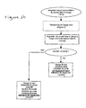
- the organization chart subject of the figures 1a and 1b shows that it is first necessary to detect the presence of a load.
- the voltage between the phase and the point of connection to the load called the Phase-Load voltage
- U_load The voltage between the phase and the point of connection to the load
- U_load a predetermined voltage
- the soft-start takes place until the maximum reference corresponding to the conduction angle maximum.
- the drive maintains this setpoint for a period of about 7 seconds to allow a compact fluorescent lamp charge to light properly.
- the drive gradually decreases the setpoint to an angle corresponding to about 40% of the maximum setpoint: in this case, since the maximum setpoint corresponds to 8.5 ms and we go down to 4 ms, it is is a little more than 40%.
- This specific instruction is maintained for 1 second to 2 seconds.
- the drive makes an acquisition of the form and value of the voltage, called Up, between the phase and the load output of the drive, on each half-period of the sector.
- the lamp is considered variable in angle conduction mode and identified as a compact fluorescent type charge.
- the inverter cuts the output, switches to angle-conduction mode and turns the lamp on again with conventional soft-start to an angle setpoint of approximately 40% of the maximum setpoint.
- a detection sequence of the minimum operating angle is then initiated, following which, in addition to the mode of cutting in angle conduction, the minimum operating angle ⁇ mini is validated for a variable compact fluorescent type load.
- the angle cut mode is validated and the load identified as variable in angle cut mode.
- the same detection sequence of the minimum angle of operation as above, the implementation of which appears in figure 2 is initiated.
- the value of the minimum operating angle ⁇ mini is validated, for a compact fluorescent type load variable.
- the current at the minimum operating angle I m is compared with the value of the current I p previously stored.
- the mode of cutting in conduction at the angle and the minimum operating angle ⁇ mini are validated, for a load identified as being of variable LED type.
- the angle cut mode and the minimum operating angle ⁇ min are validated for a load identified as being of the non-variable LED or CFL type, whose power supply in angle conduction mode is not harmful to the lamp, but still allows the user to turn on the lamp.
- a detection of the minimum angle of operation is performed from the setpoint of 4 ms.
- This set point is progressively reduced by predetermined steps, for example by 250 ⁇ s.
- predetermined steps for example to 500 ms.
- it is proceeded to the acquisition of the current on each level, half a period out of two, over a few periods in order to then be able to calculate averages.
- the highest and lowest averages are stored, the first used during the next iteration, divided by two and compared to the low average of the current setpoint.
- this angle to which the increment (for example of 250 ⁇ s) is added is stored as the minimum setpoint angle, which is the angle of the previous iterative loop.
- the decrementation is continued until reaching an angle of minimum setpoint of a default value (for example 1.5 ms for 50 Hz), which will then be stored as the minimum setpoint.
- a default value for example 1.5 ms for 50 Hz
- the voltage across a shunt resistor which is traversed by the load current is amplified by an amplifier (7).
- the output voltage of this amplifier is applied to the input of an analog digital converter (ADC), also internal or external to the microcontroller (2).
- ADC analog digital converter
- the image of this current is treated appropriate, including a comparison to a predefined threshold, during the acquisition phase that takes place over several periods of the sector.
- the method and the device of the invention allow the use of the dimmer with compact fluorescent type lamps and LED type lamps, thanks to the automatic detection procedure. They ensure in addition the detection of non-variable compact fluorescent lamps and LED lamps, and finally allow the user to overcome a configuration manipulation of the drive following the connected lamp.
Description
La présente invention a trait à un procédé de mise en fonctionnement d'un variateur de lumière sur une charge lumineuse quelconque placée en sortie du variateur, y compris les lampes fluorescentes compactes (dites lampes fluo compactes ou lampes CFL) et les lampes à diodes électroluminescentes ou lampes LED, qui remplacent de nos jours dans une large mesure les ampoules à incandescence traditionnelles notamment parce qu'elles consomment beaucoup moins d'énergie.The present invention relates to a method of operating a dimmer on any light load placed at the output of the dimmer, including compact fluorescent lamps (so-called compact fluorescent lamps or CFL lamps) and LED lamps. or LED lamps, which today replace to a large extent traditional incandescent bulbs especially because they consume much less energy.
Les configurations dans lesquelles on trouve actuellement la plupart desdites lampes fluorescentes ou LED, sont telles qu'elles peuvent être simplement et directement utilisées à la place des ampoules traditionnelles puisqu'elles sont fabriquées avec un culot traditionnel et une ampoule de volume usuel qui renferme le tube fluorescent ou les LED indispensables à ces technologies.The configurations in which most of the said fluorescent lamps or LEDs are currently found, are such that they can be simply and directly used in place of traditional bulbs since they are manufactured with a traditional base and a usual volume bulb which encloses the fluorescent tube or the LEDs indispensable to these technologies.
C'est la raison pour laquelle on peut être tenté de les utiliser dans des environnements techniques identiques, avec par exemple des accessoires de type variateurs de lumière pour régler leur luminosité, accessoires pour lesquels ces lampes posent cependant des problèmes spécifiques car constituant des charges qui ne réagissent pas nécessairement comme les charges lumineuses existantes.This is the reason why one can be tempted to use them in identical technical environments, with for example accessories of the type dimmers to adjust their brightness, accessories for which these lamps however pose specific problems because constituting charges that do not necessarily react like existing light loads.
Pour mémoire, ces charges existantes sont typiquement classées dans trois catégories selon qu'elles sont plutôt résistives, inductives ou capacitives, ces catégories ne pouvant pas être traitées de façon identique par le variateur parce qu'elles réagissent différemment aux signaux de commande, nécessitant dès lors des traitements différents en amont. L'alimentation variable des charges s'effectue en pratique au moyen d'un signal de sortie découpé dans la phase selon un mode de découpage qui dépend de la nature de la charge, impliquant une première opération de détection de la catégorie de la charge.For the record, these existing loads are typically classified into three categories depending on whether they are rather resistive, inductive or capacitive, these categories can not be treated identically by the drive because they react differently to the control signals, requiring as soon during different treatments upstream. The variable supply of charges is effected in practice by means of an output signal cut in the phase according to a switching mode which depends on the nature of the load, involving a first operation of detecting the category of the load.
Lorsqu'elle est inductive, ladite charge est alimentée selon un mode dit de conduction à l'angle. Ce mode d'alimentation convient également aux charges résistives, mais provoque des surintensités lorsque des charges de nature capacitive sont placées en sortie de l'étage d'alimentation.When it is inductive, said load is fed according to a so-called mode of conduction at the angle. This mode of supply is also suitable for resistive loads, but causes overcurrents when loads of capacitive nature are placed at the output of the supply stage.
Les récepteurs capacitifs sont plutôt alimentés selon un mode de fonctionnement dit de coupure à l'angle, selon lequel la première portion de chaque alternance est transmise à la charge alors que le reste de l'alternance est bloqué, à l'inverse du mode de conduction à l'angle qui transmet le signal du secteur à partir d'un angle de consigne. De fortes surtensions surviennent lorsque ce mode de fonctionnement de coupure à l'angle est utilisé avec des charges inductives. A la longue, ces surtensions peuvent aboutir à la destruction du variateur.The capacitive receivers are rather powered according to a mode of operation called angle cut, in which the first portion of each alternation is transmitted to the load while the rest of the alternation is blocked, unlike the mode of operation. Angle conduction that transmits the mains signal from a setpoint angle. Large surges occur when this mode of cut-off operation is used with inductive loads. In the long run, these overvoltages can lead to the destruction of the drive.
Les angles de consigne appliqués à la charge peuvent varier de 0% à 100%, ce qui sous-entend qu'une consigne de quelques pourcents doit permettre à la charge de s'allumer faiblement mais correctement (sans papillotements ou sans à-coups) avec une variation très graduelle lorsque l'angle augmente sous l'effet de l'action de l'utilisateur.The setpoint angles applied to the load can vary from 0% to 100%, which implies that a setpoint of a few percent should allow the load to light up slightly but correctly (without flickering or jerking) with a very gradual variation when the angle increases under the effect of the action of the user.
Pour réduire les risques de destruction des composants des variateurs et améliorer la durée de vie des lampes, des procédés de démarrage en douceur dits « soft-start » sont d'ailleurs utilisés, qui testent la nature des charges et gèrent leur allumage d'une manière progressive avec pour objectif une réduction des phénomènes transitoires de type surtension ou surintensité.To reduce the risk of destroying the components of the drives and to improve the service life of the lamps, soft start-up processes called "soft-start" are also used, which test the nature of the loads and manage their ignition. progressive way with the aim of reducing transients such as overvoltage or overcurrent.
Dans les variateurs actuels, qui sont conçus pour s'adapter automatiquement à la nature de la charge lors de leur mise sous tension, les procédés soft-start privilégient un démarrage en mode coupure à l'angle car il est facile de détecter les surtensions qui apparaissent lorsque les charges sont inadaptées. Le variateur est basculé en mode de conduction à l'angle lorsqu'une surtension significative est détectée.In today's drives, which are designed to automatically adapt to the nature of the load when they are powered up, the soft-start processes favor a start in cut mode at the angle because it is easy to detect the overvoltages that appear when the loads are unsuitable. The drive is switched to angle conduction mode when a significant overvoltage is detected.
Cependant, des problèmes particuliers se posent lorsque les charges lumineuses sont constituées d'ampoules de type fluo compactes ou LED, car les procédés soft-start classiques ne sont pas adaptés au mode de fonctionnement notamment des ampoules de type fluo compactes, dont la durée d'allumage excède bien souvent les durées des périodes progressives gérées par le procédé soft-start. L'angle de conduction correspondant à la consigne minimale est d'ailleurs souvent trop faible pour en permettre l'allumage, et inversement lorsque le réglage est effectué dans le sens d'une réduction de la luminosité, l'angle de conduction correspondant à ladite consigne minimale est également trop faible pour que l'ampoule reste allumée.However, particular problems arise when the light loads consist of compact fluorescent or LED type bulbs, because the conventional soft-start methods are not adapted to the operating mode including compact fluorescent type bulbs, the duration of which ignition often exceeds the durations of the progressive periods managed by the soft-start process. The conduction angle corresponding to the minimum setpoint is also often too weak to allow ignition, and conversely when the adjustment is made in the direction of a reduction in brightness, the conduction angle corresponding to said minimum setpoint is also too low for the light bulb to stay on.
D'ailleurs, le fonctionnement au voisinage de la consigne minimale est en lui-même problématique puisque, notamment selon la température de la lampe, il peut se produire un clignotement de la lampe à la fréquence de charge/décharge du ballast qui fournit la haute tension au tube fluorescent équipant les ampoules.Moreover, the operation in the vicinity of the minimum setpoint is in itself problematic since, in particular according to the temperature of the lamp, it can occur a flashing of the lamp at the load / discharge frequency of the ballast which provides the high voltage to the fluorescent tube equipping the bulbs.
Enfin, et ce n'est pas la moindre des complications, les modes d'alimentation classiques en coupure à l'angle ou en conduction à l'angle ne fonctionnent pas toujours correctement avec des ampoules de type fluo compactes ou LED, et il faut en pratique tester et configurer le mode d'alimentation pour chaque ampoule connectée, même lorsque lesdites ampoules sont commercialisées avec le label « à commande variable ».Lastly, and this is not the least of the complications, the conventional power supply modes in angle cut or in angle conduction do not always work correctly with compact fluorescent or LED type bulbs, and it is necessary to in practice test and configure the power mode for each connected bulb, even when said bulbs are marketed with the label "variable control".
Les publications de demandes de
La présente invention remédie à ces problèmes en ce que le procédé mis en oeuvre permet de commander toute charge lumineuse, y compris les lampes dites fluo compactes ou LED, autorisant une commande variable de la luminosité de ces charges dans le mode de découpage approprié. Cela n'est bien entendu possible qu'après analyse du mode de commande adéquat, pour un intervalle de valeurs de consignes correspondant à la charge, que le procédé de l'invention se propose d'identifier.The present invention overcomes these problems in that the method implemented makes it possible to control any light load, including so-called compact fluorescent lamps or LEDs, allowing variable control of the brightness of these charges in the appropriate mode of cutting. This is not of course, only after analysis of the appropriate control mode, for an interval of setpoint values corresponding to the load, that the method of the invention proposes to identify.
Ce procédé, destiné en résumé à la mise en fonctionnement d'un variateur de lumière sur une charge de type luminaire de nature quelconque placée en sortie d'un étage de puissance du variateur géré par un microcontrôleur et fournissant une alimentation variable par découpage de phase en mode soit de conduction à l'angle, soit de coupure à l'angle à partir d'un état de non alimentation en sortie de l'étage de puissance pris par le variateur en l'absence de charge, comporte à titre essentiel les différentes étapes suivantes :
- a/ détection de la présence d'une charge en sortie de l'étage d'alimentation ;
- b/ en cas de présence d'une charge, activation de l'alimentation de ladite charge en mode coupure à l'angle, et incrémentation régulière de l'angle de coupure selon un pas prédéterminé, en l'absence de surtension, jusqu'à l'obtention d'un angle maximal αM de consigne de commande, ou basculement en mode conduction à l'angle en cas d'apparition de surtensions ;
- c/ première temporisation à l'obtention de l'angle maximal αM de consigne ;
- d/ établissement de l'angle de coupure à une valeur prédéterminée αp comprise entre 40 et 50 pourcent de l'angle maximal αM de consigne de commande ;
- e/ seconde temporisation ;
- f/ acquisition, mémorisation et traitement de la tension Up aux bornes du variateur ;
- g/ comparaison de la tension Up après traitement à une valeur de tension seuil Us prédéterminée ;
- h/ activation du variateur en mode conduction à l'angle si ladite tension Up après traitement est instable suivant un critère d'instabilité prédéterminé, puis détection de l'angle minimal αm de fonctionnement avant extinction de la lampe ;
- i/ dans le cas contraire, et si la tension est supérieure à la tension seuil Us prédéterminée, activation du variateur en mode coupure à l'angle, puis détection de l'angle minimal αm de fonctionnement avant extinction de la lampe ;
- j/ si ladite tension Up après traitement est stable suivant un critère d'instabilité prédéterminé, et si la tension est inférieure à la tension seuil Us prédéterminée : acquisition, mémorisation et traitement du courant Ip durant une durée d' dans la charge, puis détection de l'angle minimal αm de fonctionnement avant extinction de la lampe ;
- k/ après validation de l'angle minimal αm, acquisition, mémorisation et traitement du courant Im dans la charge durant une durée d' ;
- l/ si Im < Ip, activation du variateur en mode conduction à l'angle ;
- m/ si Im > Ip, activation du variateur en mode coupure à l'angle.
- a / detecting the presence of a charge at the output of the power stage;
- b / in case of presence of a load, activation of the supply of said load in angle cut mode, and regular incrementation of the cutoff angle according to a predetermined step, in the absence of overvoltage, until obtaining a maximum command angle α M , or switching to the angle-conduction mode in the event of overvoltages occurring;
- c / first delay to obtain the maximum angle α M setpoint;
- d / setting the cutoff angle to a predetermined value α p between 40 and 50 percent of the maximum command angle α M ;
- e / second delay;
- f / acquisition, storage and treatment of the voltage Up at the terminals of the drive;
- g / comparing the voltage Up after processing to a threshold voltage value U s predetermined;
- h / activation of the drive in angle conduction mode if said voltage Up after treatment is unstable according to a criterion of instability predetermined, and then detecting the minimum angle α m of operation before extinguishing the lamp;
- i / otherwise, and if the voltage is greater than the threshold voltage U s predetermined activation of the drive in angle cut mode, then detection of the minimum angle α m of operation before extinguishing the lamp;
- j / if said voltage Up after processing is stable according to a predetermined instability criterion, and if the voltage is lower than the predetermined threshold voltage U s : acquisition, storage and treatment of the current I p during a period of time in the load, then detection of the minimum angle α m of operation before extinguishing the lamp;
- k / after validation of the minimum angle α m , acquisition, storage and treatment of the current I m in the load for a period of;
- l / if I m <Ip, activation of the drive in mode conduction at the angle;
- m / if I m > Ip, drive activation in angle cut mode.
Le procédé de l'invention, en plus des modes de fonctionnement traditionnels rappelés ci-dessus et basés soit sur une conduction à l'angle, soit sur une coupure à l'angle, met par conséquent également en oeuvre une détection des lampes fluo compacts et lampes LED non variables, autorisant le variateur à les alimenter uniquement en mode coupure à l'angle, seul mode de découpage qui ne détériore pas ces ampoules.The method of the invention, in addition to the traditional operating modes recalled above and based either on an angle conduction, or on a cut at the angle, therefore also implements a detection of compact fluorescent lamps. and non-variable LED lamps, allowing the drive to supply them only in angle cut mode, the only cutting mode that does not deteriorate these bulbs.
Il commence en fait comme dans les procédés de démarrage de type soft-start traditionnels en testant l'existence d'une charge inductive aux bornes du variateur. Si c'est le cas, il se produit un basculement en mode conduction à l'angle apte à gérer une telle charge.It starts in fact as in traditional soft-start startup methods by testing the existence of an inductive load across the drive. If this is the case, there occurs a switch in conduction mode at the angle capable of handling such a load.
Sinon, le procédé soft-start se déroule progressivement jusqu'à obtention de la consigne d'angle maximal. Une temporisation permet à une lampe de type fluo compacte, si elle constitue la charge, de s'allumer et de se stabiliser.Otherwise, the soft-start process proceeds progressively until the maximum angle setpoint is obtained. A delay allows a compact fluorescent lamp, if it constitutes the load, to turn on and stabilize.
Puis, le variateur descend directement à une consigne bien inférieure pour tester, par l'acquisition successive de valeurs de tension et éventuellement de courant dans la charge, le mode de fonctionnement possible pour la charge de type fluo compacte ou de type LED disposée en sortie du variateur.Then, the drive descends directly to a much lower set point for testing, by successively acquiring voltage values and possibly current in the load, the possible operating mode for the compact fluorescent type load or LED type output of the drive.
En pratique, l'acquisition de tension s'effectue n fois pour chaque demi-période du secteur, après la coupure du signal, pendant une durée d. Plus précisément encore, selon l'invention, n est compris entre 5 et 15 et la durée d est comprise entre 1 et 3 s.In practice, the voltage acquisition is performed n times for each half-period of the sector, after the signal cut, for a period d. More precisely still, according to the invention, n is between 5 and 15 and the duration d is between 1 and 3 s.
De fait, le traitement de la tension mentionné auparavant consiste à faire la moyenne des tensions acquises pour chaque demi-période du secteur pendant la durée d, et à ne mémoriser que les moyennes supérieure et inférieure. La valeur de la tension après traitement est en réalité la moyenne supérieure ainsi mémorisée, qui est donc comparée à une valeur seuil prédéterminée.In fact, the aforementioned voltage processing consists in averaging the voltages acquired for each half-period of the sector during the period d, and storing only the upper and lower averages. The value of the voltage after treatment is actually the upper average thus stored, which is therefore compared to a predetermined threshold value.
Cette comparaison détermine le mode de fonctionnement comme indiqué auparavant, le critère d'instabilité prédéterminé déterminant le fonctionnement en mode conduction à l'angle étant validé lorsque la valeur de la moyenne supérieure divisée par deux est supérieure à la moyenne inférieure.This comparison determines the operating mode as indicated previously, the predetermined instability criterion determining the operation in angle conduction mode being validated when the value of the upper average divided by two is greater than the lower average.
En pratique, une première temporisation de 1 s à 10 s est mise en oeuvre à l'issue de l'étape b/, permettant comme indiquée qu'une charge de type lampe fluo compacte ait le temps de s'allumer de manière stable. La seconde temporisation suite à l'établissement de l'angle de coupure à une valeur prédéterminée comprise entre 40 et 50% de l'angle maximal de consigne de commande est comprise entre 1 s et 5 s.In practice, a first time delay of 1 s to 10 s is implemented at the end of step b /, allowing, as indicated, that a charge of the compact fluorescent lamp type has the time to light up stably. The second delay following the setting of the cut-off angle to a predetermined value between 40 and 50% of the maximum control command angle is between 1 s and 5 s.
De préférence, l'angle maximal αm de consigne de commande correspond à une durée de 8,5 ms en 50 Hz, et la valeur prédéterminée αp de l'angle de coupure correspond à 4 ms.Preferably, the maximum command angle α m corresponds to a duration of 8.5 ms at 50 Hz, and the predetermined value α p of the cutoff angle corresponds to 4 ms.
De préférence encore, la durée d' d'acquisition, de mémorisation et de traitement du courant Ip dans la charge est comprise entre 400 et 600 ms.More preferably, the duration of acquisition, storage and treatment of the current Ip in the load is between 400 and 600 ms.
Les caractéristiques précédentes permettent la mise en place du mode de découpage ou de fonctionnement adéquat, c'est-à-dire dépendant de la charge et intégrant les spécificités des lampes de type fluo compactes et de type LED.The preceding features allow the establishment of the appropriate mode of cutting or operation, that is to say dependent on the load and incorporating the specific features of compact fluorescent lamps and LED type.
Dans la même logique, puisque l'invention s'applique à des variateurs et que le but est de les faire fonctionner correctement pour tout type de charge, y compris précisément les charges de type fluo compactes ou de type LED, il convient également de détecter l'angle minimal de fonctionnement de ces charges particulières.In the same logic, since the invention applies to drives and the goal is to make them work properly for any type of load, including For compact fluorescent or LED type loads, it is also necessary to detect the minimum operating angle of these particular loads.
Dans ce cas, une telle détection comporte les étapes ultérieures suivantes en boucle itérative pour la recherche de la consigne d'angle minimal αm lorsque le mode de coupure à l'angle ou de conduction à l'angle est activé avec la consigne initiale α p:
- n/ temporisation d'une durée t ;
- o/ acquisition, mémorisation et traitement du courant dans la charge pendant une période prédéterminée p ;
- p/ si la consigne d'angle n'est pas la consigne initiale αp, comparaison d'une valeur de courant In de la consigne courante après traitement à une valeur calculée égale à un pourcentage x de la valeur In-1 issue du traitement de courant de la consigne précédente ;
- q/ si la consigne d'angle est la consigne initiale αp, décrémentation de la consigne d'un pas p prédéterminé et retour à o/ ;
- r/ selon le résultat de la comparaison, établissement de la consigne d'angle minimal αm à la consigne précédente lorsque In ≥ xIn-1 ou établissement d'une nouvelle consigne courante par décrémentation de la consigne d'un pas p prédéterminé et retour à o/, sauf à passer sous un seuil de consigne minimale prédéterminée, laquelle devient la consigne minimale αm.
- n / time delay of a duration t;
- o / acquisition, storage and treatment of the current in the load for a predetermined period p;
- p / if the angle setpoint is not the initial setpoint α p , comparison of a current value I n of the current setpoint after processing to a computed value equal to a percentage x of the value I n-1 issue current treatment of the previous instruction;
- q / if the angle setpoint is the initial setpoint α p , decrementing the setpoint by a predetermined step p and returning to o /;
- r / according to the result of the comparison, setting the minimum angle setpoint α m to the previous setpoint when I n ≥ xI n-1 or setting a new current setpoint by decrementing the setpoint by a predetermined step p and back to o /, except to pass below a predetermined minimum setpoint, which becomes the minimum setpoint α m .
En somme, on réalise des tests successifs en abaissant progressivement l'angle de consigne pour vérifier jusqu'à quelle valeur minimale le fonctionnement des lampes est satisfaisant.In sum, successive tests are carried out by gradually lowering the setpoint angle to check up to what minimum value the operation of the lamps is satisfactory.
En pratique, l'acquisition de courant s'effectue n' fois pour une demi-période du secteur sur deux, pendant la période prédéterminée p pour chaque boucle itérative.In practice, the acquisition of current occurs n 'times for half a period of the sector out of two, during the predetermined period p for each iterative loop.
Par ailleurs, la moyenne la plus haute et la moyenne la plus basse des demi-périodes sont mémorisées pour chaque boucle itérative, et forment la base des traitements effectués pour déterminer ladite valeur minimale de fonctionnement.Furthermore, the highest average and the lowest average half-periods are stored for each iterative loop, and form the basis of the processing performed to determine said minimum operating value.
Ainsi, la valeur calculée de la consigne précédente est la moyenne haute divisée par deux, la valeur de courant après traitement de la consigne courante est la moyenne basse, et la décrémentation itérative est poursuivie tant que la seconde est supérieure à x fois la première, et stoppée dans le cas contraire.Thus, the calculated value of the previous setpoint is the high average divided by two, the current value after treatment of the current setpoint is the low average, and the iterative decrementation is continued as long as the second is greater than x times the first, and stopped in the opposite case.
Selon une possibilité, x est égale à 0,5. Par ailleurs, la période prédéterminée p est comprise entre 400 ms et 600 ms.According to one possibility, x is equal to 0.5. Moreover, the predetermined period p is between 400 ms and 600 ms.
De préférence, la décrémentation de la consigne courante s'effectue suivant des pas de l'ordre de 250 µs. L'opération d'abaissement itératif de la valeur de consigne est répétée jusqu'à une valeur minimale prédéterminée par exemple établie à une valeur de 1,5 ms, correspondant à une consigne d'angle minimale α m.Preferably, the decrementation of the current setpoint takes place in steps of the order of 250 μs. The operation of iterative lowering of the setpoint value is repeated up to a predetermined minimum value, for example set at a value of 1.5 ms, corresponding to a minimum angle setpoint α m .
L'invention va à présent être décrite en référence aux
L'organigramme faisant l'objet des
Dans ce cas, et selon les modalités classiques rappelées auparavant, la mise en place du démarrage en « soft-start » s'effectue toujours avec un mode de fonctionnement d'abord en coupure à l'angle.In this case, and in accordance with the conventional methods previously described, the implementation of the "soft-start" start-up is always carried out with a mode of operation first cut at the corner.
En l'absence de surtension, qui indique que l'on a plutôt affaire à une charge capacitive ou résistive, surtension qui provoquerait le basculement dans le mode conduction à l'angle propre aux charges inductives, le soft-start se déroule jusqu'à la consigne maximale correspondant à l'angle de conduction maximal. Le variateur maintient cette consigne pendant une durée de l'ordre de 7 s pour laisser une charge de type lampe fluo compacte s'allumer correctement.In the absence of overvoltage, which indicates that it is rather a matter of a capacitive or resistive load, overvoltage which would cause the switching in the conduction mode to the angle specific to the inductive loads, the soft-start takes place until the maximum reference corresponding to the conduction angle maximum. The drive maintains this setpoint for a period of about 7 seconds to allow a compact fluorescent lamp charge to light properly.
Puis, le variateur descend progressivement la consigne jusqu'à un angle correspondant à environ 40% de la consigne maximale : en l'espèce, puisque la consigne maximale correspond à 8,5 ms et qu'on descend à 4 ms, il s'agit d'un peu plus que 40%. Cette consigne spécifique est maintenue pendant 1 s à 2 s. Le variateur fait une acquisition de la forme et de la valeur de la tension, appelée Up, entre la phase et la sortie charge du variateur, sur chaque demi-période du secteur.Then, the drive gradually decreases the setpoint to an angle corresponding to about 40% of the maximum setpoint: in this case, since the maximum setpoint corresponds to 8.5 ms and we go down to 4 ms, it is is a little more than 40%. This specific instruction is maintained for 1 second to 2 seconds. The drive makes an acquisition of the form and value of the voltage, called Up, between the phase and the load output of the drive, on each half-period of the sector.
Si la tension est instable suivant un critère prédéfini, la lampe est considérée comme variable en mode conduction à l'angle et identifiée comme une charge de type fluo compact. Le variateur coupe la sortie, bascule en mode de conduction à l'angle et rallume la lampe à l'aide du soft-start classique jusqu'à une consigne d'angle d'environ 40% de la valeur de consigne maximale. Une séquence de détection de l'angle minimal de fonctionnement, dont la mise en oeuvre apparaît en
Si la tension est stable ET supérieure à un seuil prédéfini, le mode de découpage en coupure à l'angle est validé et la charge identifiée comme variable en mode coupure à l'angle. La même séquence de détection de l'angle minimal de fonctionnement que ci-dessus, dont la mise en oeuvre apparaît en
Enfin, si la tension est stable ET inférieure à un seuil prédéfini, sa valeur appelée Up est mémorisée, et le variateur fait une acquisition, durant environ 500 ms, de la forme et de la valeur du courant dans la charge pour cet angle spécifique de 4ms (à 50Hz), et la mémorise sous le nom de Ip. Une séquence de détection de l'angle minimal de fonctionnement, dont la mise en oeuvre apparaît en
A l'issue de cette détection, le courant à l'angle minimal de fonctionnement Im est comparé à la valeur du courant Ip précédemment mémorisé.At the end of this detection, the current at the minimum operating angle I m is compared with the value of the current I p previously stored.
Si le courant Im est inférieur au courant Ip, le mode de découpage en conduction à l'angle et l'angle minimal de fonctionnement α mini sont validés, pour une charge identifiée comme étant de type LED variable.If the current I m is lower than the current I p , the mode of cutting in conduction at the angle and the minimum operating angle α mini are validated, for a load identified as being of variable LED type.
Si le courant Im n'est pas inférieur au courant Ip, le mode de découpage en coupure à l'angle et l'angle minimal de fonctionnement α mini sont validés pour une charge identifiée comme étant de type LED ou CFL non variable, dont l'alimentation en mode conduction à l'angle n'est pas dommageable à la lampe, mais permet tout de même à l'utilisateur d'allumer la lampe.If the current I m is not less than the current I p , the angle cut mode and the minimum operating angle α min are validated for a load identified as being of the non-variable LED or CFL type, whose power supply in angle conduction mode is not harmful to the lamp, but still allows the user to turn on the lamp.
Que le variateur fonctionne en mode coupure à l'angle ou en mode conduction à l'angle, une détection de l'angle minimal de fonctionnement, dont la mise en oeuvre apparaît en
Cette consigne est progressivement diminuée par pas prédéterminés, par exemple de 250 µs. Pendant une durée prédéfinie, se montant par exemple à 500ms, il est procédé à l'acquisition du courant sur chaque palier, une demi-période sur deux, sur quelques périodes en vue de pouvoir ensuite calculer des moyennes. La moyenne la plus haute et la plus basse sont mémorisées, la première servant lors de l'itération suivante, divisée par deux et comparée à la moyenne basse de la consigne courante.This set point is progressively reduced by predetermined steps, for example by 250 μs. During a predefined period, amounting for example to 500 ms, it is proceeded to the acquisition of the current on each level, half a period out of two, over a few periods in order to then be able to calculate averages. The highest and lowest averages are stored, the first used during the next iteration, divided by two and compared to the low average of the current setpoint.
Lorsque l'angle de consigne est tel que le courant est instable et que sa valeur est inférieure à 50% de la valeur du courant pour l'angle de consigne précédent, cet angle auquel on ajoute l'incrément (par exemple de 250µs) est mémorisé comme l'angle de consigne minimum, qui est donc l'angle de la boucle itérative précédente.When the setpoint angle is such that the current is unstable and its value is less than 50% of the value of the current for the preceding setpoint angle, this angle, to which the increment (for example of 250 μs) is added is stored as the minimum setpoint angle, which is the angle of the previous iterative loop.
Dans l'hypothèse où le courant est stable et supérieur à 50% de la consigne précédente, la décrémentation est poursuivie jusqu'à arriver à un angle de consigne minimal d'une valeur fixée par défaut (à titre d'exemple 1,5 ms pour 50 Hz), qui sera alors mémorisée comme angle de consigne minimal.In the event that the current is stable and greater than 50% of the previous instruction, the decrementation is continued until reaching an angle of minimum setpoint of a default value (for example 1.5 ms for 50 Hz), which will then be stored as the minimum setpoint.
La
- Un étage de puissance (1) à base de semi-conducteurs adaptés à la puissance à commander.
- Une unité de contrôle (2) (typiquement un microcontrôleur) permettant de commander l'étage de puissance (1) pour bloquer ou laisser passer le courant pour alimenter la charge, et faire les différents traitements logiques nécessaires à la détection de la charge connectée.
- Une unité de détection (3,6) des surtensions et/ou de la tension de présence charge comportant un pont de résistance (3) et un étage comparateur (6).
- Une unité de détection du passage par zéro du courant (4) dans la charge.
- Une unité de détection du passage par zéro de la tension (5).
- Une unité permettant l'acquisition de la tension aux bornes du variateur (6).
- Une unité permettant l'acquisition du courant (7) qui traverse la charge.
- A power stage (1) based on semiconductors adapted to the power to be controlled.
- A control unit (2) (typically a microcontroller) for controlling the power stage (1) to block or pass the current to feed the load, and make the different logic processes necessary for the detection of the connected load.
- A detection unit (3,6) for overvoltages and / or charge present voltage having a resistance bridge (3) and a comparator stage (6).
- A unit for detecting the zero crossing of the current (4) in the load.
- A unit for detecting the zero crossing of the voltage (5).
- A unit for acquiring the voltage across the drive (6).
- A unit for acquiring the current (7) passing through the load.
Le fonctionnement est le suivant :
- Une fraction de la tension entre PHASE et CHARGE est appliquée à l'entrée d'un convertisseur analogique numérique (ADC), interne ou externe au microcontrôleur (2) (représenté ici en interne) via un pont de résistance (3). Sur une demi-période du secteur, cette tension fait l'objet d'un traitement approprié, notamment d'une comparaison à un seuil prédéfini (REF) via l'étage comparateur (6), pendant la phase d'acquisition qui se déroule sur plusieurs périodes du secteur.
- A fraction of the voltage between PHASE and CHARGE is applied to the input of an analog digital converter (ADC), internal or external to the microcontroller (2) (shown here internally) via a resistance bridge (3). Over a half-period of the sector, this voltage is the subject of an appropriate treatment, in particular a comparison with a predefined threshold (REF) via the comparator stage (6), during the acquisition phase which takes place over several periods of the sector.
Pour ce qui concerne l'acquisition du courant qui traverse la charge, la tension aux bornes d'une résistance « shunt » qui est traversée par le courant de la charge, est amplifiée par un amplificateur (7). La tension de sortie de cet amplificateur est appliquée à l'entrée d'un convertisseur analogique numérique (ADC), également interne ou externe au microcontrôleur (2). Durant une demi-période sur deux du secteur, l'image de ce courant fait l'objet d'un traitement approprié, notamment d'une comparaison à un seuil prédéfini, pendant la phase d'acquisition qui se déroule sur plusieurs périodes du secteur.As regards the acquisition of the current flowing through the load, the voltage across a shunt resistor which is traversed by the load current is amplified by an amplifier (7). The output voltage of this amplifier is applied to the input of an analog digital converter (ADC), also internal or external to the microcontroller (2). During half of every half of the sector, the image of this current is treated appropriate, including a comparison to a predefined threshold, during the acquisition phase that takes place over several periods of the sector.
Comme indiqué auparavant, le procédé et le dispositif de l'invention permettent l'utilisation du variateur avec des lampes de type fluo compactes et des lampes de type LED, grâce à la procédure de détection automatique. Ils assurent au surplus la détection des lampes fluo compactes non variables et des lampes LED, et permettent enfin à l'utilisateur de s'affranchir d'une manipulation de configuration du variateur suivant la lampe connectée.As indicated above, the method and the device of the invention allow the use of the dimmer with compact fluorescent type lamps and LED type lamps, thanks to the automatic detection procedure. They ensure in addition the detection of non-variable compact fluorescent lamps and LED lamps, and finally allow the user to overcome a configuration manipulation of the drive following the connected lamp.
Claims (18)
- A method for operating a light dimmer on a luminaire-type load of any nature placed at the output of a power stage (2) of the dimmer managed by a microcontroller providing a variable power supply by phase section either in angle conduction mode, or angle cut mode, from a non-powered state at the output of the power stage (2) assumed by the dimmer when there is no load, including the following steps:a/ detecting the presence of a load at the output of the power stage;b/ if a load is present, activating the power supply of said load in angle cut mode, and regularly incrementing the cut angle by a predetermined pitch, when there is no overvoltage, until obtaining a maximum command setpoint angle αM, or switching into angle conduction mode if overvoltages appear;c/ first time delay upon obtaining the maximum setpoint angle aM;d/ establishing the cut angle at a predetermined value αp comprised between 40 and 50° of the maximum control setpoint angle αM;e/ second time delay;f/ acquiring, storing and processing the voltage Up across the terminals of the dimmer;g/ comparing the voltage Up after processing to a predetermined threshold voltage value Us;h/ activating the dimmer in angle conduction mode if said voltage Up after processing is unstable according to a predetermined instability criterion, then detecting the minimum operating angle αm before extinguishing the bulb;i/ otherwise, and if the voltage is above the predetermined threshold voltage Us, activating the dimmer in angle cut mode, then detecting the minimum operating angle αm before extinguishing the bulb;j/ if said voltage Up after processing is stable according to a predetermined instability criterion, and if the voltage is below the predetermined threshold voltage Us: acquiring, storing and processing the current Ip during a duration d' in the load, then detecting the minimum operating angle αm before extinguishing the bulb;k/ after validating the minimum angle αm, acquiring, storing and processing the current Im in the load during a duration d';l/ if Im < Ip, activating the dimmer in angle conduction mode;m/ if Im > Ip, activating the dimmer in angle cut mode.
- The method for operating a light dimmer according to the preceding claim, characterized in that the voltage acquisition Up is done n times for each half-period of the sector, after cut off of the signal, during a duration d.
- The method for operating a light dimmer according to the preceding claim, characterized in that n is comprised between 5 and 15 and the duration d is comprised between 1 s and 3 s.
- The method for operating a light dimmer according to one of the preceding claims, characterized in that the processing of the voltage Up consists of taking the average of the voltages required for each half-period of the sector during the duration d, and only storing the highest and lowest averages.
- The method for operating a light dimmer according to the preceding claim, characterized in that the value of the voltage Up after processing is the highest average.
- The method for operating a light dimmer according to one of claims 4 and 5, characterized in that the predetermined instability criterion is validated when the highest average value divided by two is greater than the lowest average.
- The method for operating a light dimmer according to one of the preceding claims, characterized in that the duration of the first time delay is comprised between 1 s and 10 s.
- The method for operating a light dimmer according to one of the preceding claims, characterized in that the duration of the second time delay is comprised between 1 s and 5 s.
- The method for operating a light dimmer according to one of the preceding claims, characterized in that the maximum control setpoint angle αM corresponds to a duration of 8.5 ms at 50 Hz, and the predetermined value αp of the cut angle corresponds to 4 ms.
- The method for operating a light dimmer according to one of the preceding claims, characterized in that the duration d' is comprised between 400 and 600 ms.
- The method for operating a light dimmer according to one of the preceding claims, characterized by the following subsequent steps in an iterative loop to look for the minimum angle setpoint αm when the angle cut or angle conduction mode is activated with the initial setpoint αp:n/ time delay with a duration t;o/ acquisition, storage and processing of the current in the load during a predetermined period p;p/ if the angle setpoint is not the initial setpoint αp, comparison of a current value In of the current setpoint after processing to a calculated value equal to a percentage x of the value In-1 resulting from the current processing of the preceding setpoint;q/ if the angle setpoint is the initial setpoint αp, decrementing the setpoint by a predetermined pitch p and returning to o/;r/ based on the outcome of the comparison, establishing the minimum angle setpoint αm at the preceding setpoint when In ≥ xIn-1 or establishing a new current setpoint by decrementing the setpoint by a predetermined pitch p and returning to o/, unless dropping below a predetermined minimum setpoint threshold, which becomes the minimum setpoint αm.
- The method for operating a light dimmer according to the preceding claim, characterized in that the current acquisition is done n' times for every other half-period of the sector, during the predetermined period p for each iterative loop.
- The method for operating a light dimmer according to the preceding claim, characterized in that the highest average and the lowest average of the half-periods are stored for each iterative loop.
- The method for operating a light dimmer according to the preceding claim, characterized in that the calculated value of the preceding setpoint being the upper average divided by two, and the current value after processing of the current setpoint being the lower average, the iterative decrementing is continued as long as the second is x times higher than the first, and stopped otherwise.
- The method for operating a light dimmer according to the preceding claim, characterized in that x is equal to 0.5.
- The method for operating a light dimmer according to one of claims 11 to 15, characterized in that the predetermined period p is comprised between 400 ms and 600 ms.
- The method for operating a light dimmer according to one of claims 11 to 16, characterized in that the decrementing of the current setpoint is done by pitches of approximately 250 µs.
- The method for operating a light dimmer according to any one of claims 11 to 17, characterized in that the minimum setpoint angle αm is established for a value of 1.5 ms.
Priority Applications (1)
| Application Number | Priority Date | Filing Date | Title |
|---|---|---|---|
| EP10306328.5A EP2461652B1 (en) | 2010-12-01 | 2010-12-01 | Method for starting a dimmer switch |
Applications Claiming Priority (1)
| Application Number | Priority Date | Filing Date | Title |
|---|---|---|---|
| EP10306328.5A EP2461652B1 (en) | 2010-12-01 | 2010-12-01 | Method for starting a dimmer switch |
Publications (2)
| Publication Number | Publication Date |
|---|---|
| EP2461652A1 EP2461652A1 (en) | 2012-06-06 |
| EP2461652B1 true EP2461652B1 (en) | 2014-02-26 |
Family
ID=44144863
Family Applications (1)
| Application Number | Title | Priority Date | Filing Date |
|---|---|---|---|
| EP10306328.5A Active EP2461652B1 (en) | 2010-12-01 | 2010-12-01 | Method for starting a dimmer switch |
Country Status (1)
| Country | Link |
|---|---|
| EP (1) | EP2461652B1 (en) |
Family Cites Families (4)
| Publication number | Priority date | Publication date | Assignee | Title |
|---|---|---|---|---|
| DE4310723A1 (en) * | 1993-04-01 | 1994-10-06 | Abb Patent Gmbh | Method for controlling the alternating current in a load circuit and device for carrying out the method |
| FR2802360B1 (en) * | 1999-12-14 | 2002-03-01 | Legrand Sa | METHOD AND DEVICE FOR ELECTRIC POWER SUPPLY OF A LOAD BY A DRIVE HAS AT LEAST ONE SWITCH CONTROLLED |
| FR2856236B1 (en) * | 2003-06-16 | 2005-08-05 | Hager Electro Sas | METHOD AND DEVICE FOR SELF-ADAPTING A VARIATOR TO A LOAD |
| US8339062B2 (en) * | 2008-05-15 | 2012-12-25 | Marko Cencur | Method for dimming non-linear loads using an AC phase control scheme and a universal dimmer using the method |
-
2010
- 2010-12-01 EP EP10306328.5A patent/EP2461652B1/en active Active
Also Published As
| Publication number | Publication date |
|---|---|
| EP2461652A1 (en) | 2012-06-06 |
Similar Documents
| Publication | Publication Date | Title |
|---|---|---|
| EP0066481A1 (en) | Electronic supply apparatus for discharge lamps | |
| FR2851793A1 (en) | MOTOR STARTER COMPRISING AN ELECTRIC STARTER MOTOR | |
| FR2922374A1 (en) | CURRENT SUPPRESSION DEVICE | |
| FR2775414A1 (en) | Microprocessor controlled starter for discharge lamp | |
| FR2773432A1 (en) | Lighting control apparatus for discharge lamp used in headlight of motor vehicle | |
| FR2949909A1 (en) | METHOD OF USING AN AUTONOMOUS SYSTEM CONNECTED TO A BATTERY | |
| EP0296558B1 (en) | Power supply device for a discharge lamp | |
| EP2461652B1 (en) | Method for starting a dimmer switch | |
| FR2542559A1 (en) | ||
| FR2874151A1 (en) | LAMP IGNITION APPARATUS | |
| FR2946489A1 (en) | ELECTRONIC BALLAST AND METHOD FOR OPERATING A DISCHARGE LAMP | |
| EP1560474A2 (en) | Protection circuit for a switched mode power suplly and lighting device for a vehicle | |
| EP3684145B1 (en) | Method and device for controlling the operation of a dimmer switch for a light | |
| FR2646538A1 (en) | Motor vehicle lighting device including means of protection against short-circuits | |
| FR2810494A1 (en) | Lighting circuit for discharge lamp for motor vehicle headlamp has circuit to detect applied voltage to lamp to determine lamp operation state | |
| EP1784059A1 (en) | Method of securely operating a dimmer for a light | |
| FR3045271A3 (en) | CIRCUIT ARRANGEMENT FOR GRADING LED LIGHT SOURCES | |
| FR2791219A1 (en) | LIGHTING CONTROL DEVICE FOR A DISCHARGE LAMP | |
| EP2741587B1 (en) | Device for varying the intensity of the light in luminous charges | |
| EP1414144B1 (en) | Method and apparatus for the average power control of an AC load | |
| EP1931181B1 (en) | Ballast for a discharge lamp | |
| EP2037287A1 (en) | Method of detecting a failure in a system for supplying an electrical charge | |
| EP1683399B1 (en) | Lighting fixture and method for operating same | |
| EP2634900A1 (en) | Two-wire dimmer | |
| FR2857214A1 (en) | Discharge lamp starting circuit, has emission acceleration control unit to transmit higher power when lamp is started initially, and regulate power so that rate of power reduction increases when lamp voltage increases |
Legal Events
| Date | Code | Title | Description |
|---|---|---|---|
| PUAI | Public reference made under article 153(3) epc to a published international application that has entered the european phase |
Free format text: ORIGINAL CODE: 0009012 |
|
| AK | Designated contracting states |
Kind code of ref document: A1 Designated state(s): AL AT BE BG CH CY CZ DE DK EE ES FI FR GB GR HR HU IE IS IT LI LT LU LV MC MK MT NL NO PL PT RO RS SE SI SK SM TR |
|
| AX | Request for extension of the european patent |
Extension state: BA ME |
|
| 17P | Request for examination filed |
Effective date: 20121123 |
|
| GRAP | Despatch of communication of intention to grant a patent |
Free format text: ORIGINAL CODE: EPIDOSNIGR1 |
|
| INTG | Intention to grant announced |
Effective date: 20131002 |
|
| GRAS | Grant fee paid |
Free format text: ORIGINAL CODE: EPIDOSNIGR3 |
|
| GRAA | (expected) grant |
Free format text: ORIGINAL CODE: 0009210 |
|
| AK | Designated contracting states |
Kind code of ref document: B1 Designated state(s): AL AT BE BG CH CY CZ DE DK EE ES FI FR GB GR HR HU IE IS IT LI LT LU LV MC MK MT NL NO PL PT RO RS SE SI SK SM TR |
|
| REG | Reference to a national code |
Ref country code: GB Ref legal event code: FG4D Free format text: NOT ENGLISH |
|
| REG | Reference to a national code |
Ref country code: CH Ref legal event code: EP |
|
| REG | Reference to a national code |
Ref country code: AT Ref legal event code: REF Ref document number: 654212 Country of ref document: AT Kind code of ref document: T Effective date: 20140315 |
|
| REG | Reference to a national code |
Ref country code: IE Ref legal event code: FG4D Free format text: LANGUAGE OF EP DOCUMENT: FRENCH |
|
| REG | Reference to a national code |
Ref country code: DE Ref legal event code: R096 Ref document number: 602010013729 Country of ref document: DE Effective date: 20140410 |
|
| REG | Reference to a national code |
Ref country code: NL Ref legal event code: VDEP Effective date: 20140226 |
|
| REG | Reference to a national code |
Ref country code: AT Ref legal event code: MK05 Ref document number: 654212 Country of ref document: AT Kind code of ref document: T Effective date: 20140226 |
|
| REG | Reference to a national code |
Ref country code: LT Ref legal event code: MG4D |
|
| PG25 | Lapsed in a contracting state [announced via postgrant information from national office to epo] |
Ref country code: IS Free format text: LAPSE BECAUSE OF FAILURE TO SUBMIT A TRANSLATION OF THE DESCRIPTION OR TO PAY THE FEE WITHIN THE PRESCRIBED TIME-LIMIT Effective date: 20140626 Ref country code: NO Free format text: LAPSE BECAUSE OF FAILURE TO SUBMIT A TRANSLATION OF THE DESCRIPTION OR TO PAY THE FEE WITHIN THE PRESCRIBED TIME-LIMIT Effective date: 20140526 Ref country code: LT Free format text: LAPSE BECAUSE OF FAILURE TO SUBMIT A TRANSLATION OF THE DESCRIPTION OR TO PAY THE FEE WITHIN THE PRESCRIBED TIME-LIMIT Effective date: 20140226 |
|
| PG25 | Lapsed in a contracting state [announced via postgrant information from national office to epo] |
Ref country code: FI Free format text: LAPSE BECAUSE OF FAILURE TO SUBMIT A TRANSLATION OF THE DESCRIPTION OR TO PAY THE FEE WITHIN THE PRESCRIBED TIME-LIMIT Effective date: 20140226 Ref country code: AT Free format text: LAPSE BECAUSE OF FAILURE TO SUBMIT A TRANSLATION OF THE DESCRIPTION OR TO PAY THE FEE WITHIN THE PRESCRIBED TIME-LIMIT Effective date: 20140226 Ref country code: NL Free format text: LAPSE BECAUSE OF FAILURE TO SUBMIT A TRANSLATION OF THE DESCRIPTION OR TO PAY THE FEE WITHIN THE PRESCRIBED TIME-LIMIT Effective date: 20140226 Ref country code: PT Free format text: LAPSE BECAUSE OF FAILURE TO SUBMIT A TRANSLATION OF THE DESCRIPTION OR TO PAY THE FEE WITHIN THE PRESCRIBED TIME-LIMIT Effective date: 20140626 Ref country code: SE Free format text: LAPSE BECAUSE OF FAILURE TO SUBMIT A TRANSLATION OF THE DESCRIPTION OR TO PAY THE FEE WITHIN THE PRESCRIBED TIME-LIMIT Effective date: 20140226 Ref country code: CY Free format text: LAPSE BECAUSE OF FAILURE TO SUBMIT A TRANSLATION OF THE DESCRIPTION OR TO PAY THE FEE WITHIN THE PRESCRIBED TIME-LIMIT Effective date: 20140226 |
|
| PG25 | Lapsed in a contracting state [announced via postgrant information from national office to epo] |
Ref country code: LV Free format text: LAPSE BECAUSE OF FAILURE TO SUBMIT A TRANSLATION OF THE DESCRIPTION OR TO PAY THE FEE WITHIN THE PRESCRIBED TIME-LIMIT Effective date: 20140226 Ref country code: RS Free format text: LAPSE BECAUSE OF FAILURE TO SUBMIT A TRANSLATION OF THE DESCRIPTION OR TO PAY THE FEE WITHIN THE PRESCRIBED TIME-LIMIT Effective date: 20140226 Ref country code: HR Free format text: LAPSE BECAUSE OF FAILURE TO SUBMIT A TRANSLATION OF THE DESCRIPTION OR TO PAY THE FEE WITHIN THE PRESCRIBED TIME-LIMIT Effective date: 20140226 |
|
| PG25 | Lapsed in a contracting state [announced via postgrant information from national office to epo] |
Ref country code: CZ Free format text: LAPSE BECAUSE OF FAILURE TO SUBMIT A TRANSLATION OF THE DESCRIPTION OR TO PAY THE FEE WITHIN THE PRESCRIBED TIME-LIMIT Effective date: 20140226 Ref country code: DK Free format text: LAPSE BECAUSE OF FAILURE TO SUBMIT A TRANSLATION OF THE DESCRIPTION OR TO PAY THE FEE WITHIN THE PRESCRIBED TIME-LIMIT Effective date: 20140226 Ref country code: RO Free format text: LAPSE BECAUSE OF FAILURE TO SUBMIT A TRANSLATION OF THE DESCRIPTION OR TO PAY THE FEE WITHIN THE PRESCRIBED TIME-LIMIT Effective date: 20140226 Ref country code: EE Free format text: LAPSE BECAUSE OF FAILURE TO SUBMIT A TRANSLATION OF THE DESCRIPTION OR TO PAY THE FEE WITHIN THE PRESCRIBED TIME-LIMIT Effective date: 20140226 |
|
| REG | Reference to a national code |
Ref country code: DE Ref legal event code: R097 Ref document number: 602010013729 Country of ref document: DE |
|
| PG25 | Lapsed in a contracting state [announced via postgrant information from national office to epo] |
Ref country code: ES Free format text: LAPSE BECAUSE OF FAILURE TO SUBMIT A TRANSLATION OF THE DESCRIPTION OR TO PAY THE FEE WITHIN THE PRESCRIBED TIME-LIMIT Effective date: 20140226 Ref country code: SK Free format text: LAPSE BECAUSE OF FAILURE TO SUBMIT A TRANSLATION OF THE DESCRIPTION OR TO PAY THE FEE WITHIN THE PRESCRIBED TIME-LIMIT Effective date: 20140226 Ref country code: PL Free format text: LAPSE BECAUSE OF FAILURE TO SUBMIT A TRANSLATION OF THE DESCRIPTION OR TO PAY THE FEE WITHIN THE PRESCRIBED TIME-LIMIT Effective date: 20140226 |
|
| PLBE | No opposition filed within time limit |
Free format text: ORIGINAL CODE: 0009261 |
|
| STAA | Information on the status of an ep patent application or granted ep patent |
Free format text: STATUS: NO OPPOSITION FILED WITHIN TIME LIMIT |
|
| 26N | No opposition filed |
Effective date: 20141127 |
|
| REG | Reference to a national code |
Ref country code: DE Ref legal event code: R097 Ref document number: 602010013729 Country of ref document: DE Effective date: 20141127 |
|
| PG25 | Lapsed in a contracting state [announced via postgrant information from national office to epo] |
Ref country code: IT Free format text: LAPSE BECAUSE OF FAILURE TO SUBMIT A TRANSLATION OF THE DESCRIPTION OR TO PAY THE FEE WITHIN THE PRESCRIBED TIME-LIMIT Effective date: 20140226 |
|
| REG | Reference to a national code |
Ref country code: CH Ref legal event code: NV Representative=s name: RENTSCH PARTNER AG, CH |
|
| PG25 | Lapsed in a contracting state [announced via postgrant information from national office to epo] |
Ref country code: SI Free format text: LAPSE BECAUSE OF FAILURE TO SUBMIT A TRANSLATION OF THE DESCRIPTION OR TO PAY THE FEE WITHIN THE PRESCRIBED TIME-LIMIT Effective date: 20140226 |
|
| PG25 | Lapsed in a contracting state [announced via postgrant information from national office to epo] |
Ref country code: BE Free format text: LAPSE BECAUSE OF NON-PAYMENT OF DUE FEES Effective date: 20141231 |
|
| PG25 | Lapsed in a contracting state [announced via postgrant information from national office to epo] |
Ref country code: LU Free format text: LAPSE BECAUSE OF FAILURE TO SUBMIT A TRANSLATION OF THE DESCRIPTION OR TO PAY THE FEE WITHIN THE PRESCRIBED TIME-LIMIT Effective date: 20141201 |
|
| GBPC | Gb: european patent ceased through non-payment of renewal fee |
Effective date: 20141201 |
|
| REG | Reference to a national code |
Ref country code: IE Ref legal event code: MM4A |
|
| PG25 | Lapsed in a contracting state [announced via postgrant information from national office to epo] |
Ref country code: GB Free format text: LAPSE BECAUSE OF NON-PAYMENT OF DUE FEES Effective date: 20141201 Ref country code: IE Free format text: LAPSE BECAUSE OF NON-PAYMENT OF DUE FEES Effective date: 20141201 |
|
| REG | Reference to a national code |
Ref country code: FR Ref legal event code: PLFP Year of fee payment: 6 |
|
| PG25 | Lapsed in a contracting state [announced via postgrant information from national office to epo] |
Ref country code: SM Free format text: LAPSE BECAUSE OF FAILURE TO SUBMIT A TRANSLATION OF THE DESCRIPTION OR TO PAY THE FEE WITHIN THE PRESCRIBED TIME-LIMIT Effective date: 20140226 |
|
| PG25 | Lapsed in a contracting state [announced via postgrant information from national office to epo] |
Ref country code: MC Free format text: LAPSE BECAUSE OF FAILURE TO SUBMIT A TRANSLATION OF THE DESCRIPTION OR TO PAY THE FEE WITHIN THE PRESCRIBED TIME-LIMIT Effective date: 20140226 |
|
| PG25 | Lapsed in a contracting state [announced via postgrant information from national office to epo] |
Ref country code: GR Free format text: LAPSE BECAUSE OF FAILURE TO SUBMIT A TRANSLATION OF THE DESCRIPTION OR TO PAY THE FEE WITHIN THE PRESCRIBED TIME-LIMIT Effective date: 20140527 Ref country code: BG Free format text: LAPSE BECAUSE OF FAILURE TO SUBMIT A TRANSLATION OF THE DESCRIPTION OR TO PAY THE FEE WITHIN THE PRESCRIBED TIME-LIMIT Effective date: 20140226 |
|
| PG25 | Lapsed in a contracting state [announced via postgrant information from national office to epo] |
Ref country code: MT Free format text: LAPSE BECAUSE OF FAILURE TO SUBMIT A TRANSLATION OF THE DESCRIPTION OR TO PAY THE FEE WITHIN THE PRESCRIBED TIME-LIMIT Effective date: 20140226 Ref country code: HU Free format text: LAPSE BECAUSE OF FAILURE TO SUBMIT A TRANSLATION OF THE DESCRIPTION OR TO PAY THE FEE WITHIN THE PRESCRIBED TIME-LIMIT; INVALID AB INITIO Effective date: 20101201 |
|
| REG | Reference to a national code |
Ref country code: FR Ref legal event code: PLFP Year of fee payment: 7 |
|
| REG | Reference to a national code |
Ref country code: CH Ref legal event code: PCAR Free format text: NEW ADDRESS: BELLERIVESTRASSE 203 POSTFACH, 8034 ZUERICH (CH) |
|
| REG | Reference to a national code |
Ref country code: FR Ref legal event code: PLFP Year of fee payment: 8 |
|
| PG25 | Lapsed in a contracting state [announced via postgrant information from national office to epo] |
Ref country code: MK Free format text: LAPSE BECAUSE OF FAILURE TO SUBMIT A TRANSLATION OF THE DESCRIPTION OR TO PAY THE FEE WITHIN THE PRESCRIBED TIME-LIMIT Effective date: 20140226 |
|
| PG25 | Lapsed in a contracting state [announced via postgrant information from national office to epo] |
Ref country code: AL Free format text: LAPSE BECAUSE OF FAILURE TO SUBMIT A TRANSLATION OF THE DESCRIPTION OR TO PAY THE FEE WITHIN THE PRESCRIBED TIME-LIMIT Effective date: 20140226 |
|
| PGFP | Annual fee paid to national office [announced via postgrant information from national office to epo] |
Ref country code: CH Payment date: 20230109 Year of fee payment: 13 |
|
| PGFP | Annual fee paid to national office [announced via postgrant information from national office to epo] |
Ref country code: DE Payment date: 20221228 Year of fee payment: 13 |
|
| P01 | Opt-out of the competence of the unified patent court (upc) registered |
Effective date: 20230606 |
|
| PGFP | Annual fee paid to national office [announced via postgrant information from national office to epo] |
Ref country code: TR Payment date: 20231121 Year of fee payment: 14 Ref country code: FR Payment date: 20231227 Year of fee payment: 14 |