EP2461504A2 - Verfahren zur übertragung von steuerinformationen und vorrichtung dafür - Google Patents
Verfahren zur übertragung von steuerinformationen und vorrichtung dafür Download PDFInfo
- Publication number
- EP2461504A2 EP2461504A2 EP10804690A EP10804690A EP2461504A2 EP 2461504 A2 EP2461504 A2 EP 2461504A2 EP 10804690 A EP10804690 A EP 10804690A EP 10804690 A EP10804690 A EP 10804690A EP 2461504 A2 EP2461504 A2 EP 2461504A2
- Authority
- EP
- European Patent Office
- Prior art keywords
- frequency band
- channel information
- transmitting
- reference signal
- base station
- Prior art date
- Legal status (The legal status is an assumption and is not a legal conclusion. Google has not performed a legal analysis and makes no representation as to the accuracy of the status listed.)
- Withdrawn
Links
- 238000000034 method Methods 0.000 title claims abstract description 102
- 230000005540 biological transmission Effects 0.000 claims abstract description 201
- 238000004891 communication Methods 0.000 claims abstract description 33
- 230000002776 aggregation Effects 0.000 description 20
- 238000004220 aggregation Methods 0.000 description 20
- 238000005259 measurement Methods 0.000 description 14
- 230000000737 periodic effect Effects 0.000 description 13
- 238000005516 engineering process Methods 0.000 description 12
- 230000006870 function Effects 0.000 description 11
- 230000011664 signaling Effects 0.000 description 10
- 239000000969 carrier Substances 0.000 description 6
- 238000013468 resource allocation Methods 0.000 description 6
- 230000008054 signal transmission Effects 0.000 description 6
- 238000010295 mobile communication Methods 0.000 description 5
- 238000001774 stimulated Raman spectroscopy Methods 0.000 description 5
- 101000741965 Homo sapiens Inactive tyrosine-protein kinase PRAG1 Proteins 0.000 description 4
- 102100038659 Inactive tyrosine-protein kinase PRAG1 Human genes 0.000 description 4
- 230000000694 effects Effects 0.000 description 4
- 230000008569 process Effects 0.000 description 3
- 241000760358 Enodes Species 0.000 description 2
- 230000007774 longterm Effects 0.000 description 2
- 239000011159 matrix material Substances 0.000 description 2
- VTWDKFNVVLAELH-UHFFFAOYSA-N 2-methylcyclohexa-2,5-diene-1,4-dione Chemical compound CC1=CC(=O)C=CC1=O VTWDKFNVVLAELH-UHFFFAOYSA-N 0.000 description 1
- 235000008694 Humulus lupulus Nutrition 0.000 description 1
- 230000004913 activation Effects 0.000 description 1
- 230000002730 additional effect Effects 0.000 description 1
- 238000001724 coherent Stokes Raman spectroscopy Methods 0.000 description 1
- 125000004122 cyclic group Chemical group 0.000 description 1
- 230000003247 decreasing effect Effects 0.000 description 1
- 238000007429 general method Methods 0.000 description 1
- 238000007726 management method Methods 0.000 description 1
- 238000013507 mapping Methods 0.000 description 1
- 238000012986 modification Methods 0.000 description 1
- 230000004048 modification Effects 0.000 description 1
- 230000003287 optical effect Effects 0.000 description 1
- 230000010363 phase shift Effects 0.000 description 1
- 238000012545 processing Methods 0.000 description 1
- 230000004044 response Effects 0.000 description 1
- 238000005070 sampling Methods 0.000 description 1
- 230000003068 static effect Effects 0.000 description 1
- 230000001502 supplementing effect Effects 0.000 description 1
Images


Classifications
-
- H—ELECTRICITY
- H04—ELECTRIC COMMUNICATION TECHNIQUE
- H04L—TRANSMISSION OF DIGITAL INFORMATION, e.g. TELEGRAPHIC COMMUNICATION
- H04L5/00—Arrangements affording multiple use of the transmission path
- H04L5/0091—Signalling for the administration of the divided path, e.g. signalling of configuration information
- H04L5/0094—Indication of how sub-channels of the path are allocated
-
- H—ELECTRICITY
- H04—ELECTRIC COMMUNICATION TECHNIQUE
- H04L—TRANSMISSION OF DIGITAL INFORMATION, e.g. TELEGRAPHIC COMMUNICATION
- H04L5/00—Arrangements affording multiple use of the transmission path
- H04L5/003—Arrangements for allocating sub-channels of the transmission path
- H04L5/0053—Allocation of signalling, i.e. of overhead other than pilot signals
-
- H—ELECTRICITY
- H04—ELECTRIC COMMUNICATION TECHNIQUE
- H04W—WIRELESS COMMUNICATION NETWORKS
- H04W72/00—Local resource management
- H04W72/04—Wireless resource allocation
- H04W72/044—Wireless resource allocation based on the type of the allocated resource
- H04W72/0453—Resources in frequency domain, e.g. a carrier in FDMA
-
- H—ELECTRICITY
- H04—ELECTRIC COMMUNICATION TECHNIQUE
- H04W—WIRELESS COMMUNICATION NETWORKS
- H04W72/00—Local resource management
- H04W72/20—Control channels or signalling for resource management
- H04W72/23—Control channels or signalling for resource management in the downlink direction of a wireless link, i.e. towards a terminal
-
- H—ELECTRICITY
- H04—ELECTRIC COMMUNICATION TECHNIQUE
- H04L—TRANSMISSION OF DIGITAL INFORMATION, e.g. TELEGRAPHIC COMMUNICATION
- H04L5/00—Arrangements affording multiple use of the transmission path
- H04L5/0001—Arrangements for dividing the transmission path
- H04L5/0003—Two-dimensional division
- H04L5/0005—Time-frequency
- H04L5/0007—Time-frequency the frequencies being orthogonal, e.g. OFDM(A) or DMT
- H04L5/001—Time-frequency the frequencies being orthogonal, e.g. OFDM(A) or DMT the frequencies being arranged in component carriers
-
- H—ELECTRICITY
- H04—ELECTRIC COMMUNICATION TECHNIQUE
- H04L—TRANSMISSION OF DIGITAL INFORMATION, e.g. TELEGRAPHIC COMMUNICATION
- H04L5/00—Arrangements affording multiple use of the transmission path
- H04L5/003—Arrangements for allocating sub-channels of the transmission path
- H04L5/0048—Allocation of pilot signals, i.e. of signals known to the receiver
-
- H—ELECTRICITY
- H04—ELECTRIC COMMUNICATION TECHNIQUE
- H04L—TRANSMISSION OF DIGITAL INFORMATION, e.g. TELEGRAPHIC COMMUNICATION
- H04L5/00—Arrangements affording multiple use of the transmission path
- H04L5/003—Arrangements for allocating sub-channels of the transmission path
- H04L5/0078—Timing of allocation
- H04L5/0082—Timing of allocation at predetermined intervals
-
- H—ELECTRICITY
- H04—ELECTRIC COMMUNICATION TECHNIQUE
- H04W—WIRELESS COMMUNICATION NETWORKS
- H04W24/00—Supervisory, monitoring or testing arrangements
- H04W24/10—Scheduling measurement reports ; Arrangements for measurement reports
Definitions
- the present invention relates to a wireless communication system. And, more particularly, the present invention relates to a method for transmitting via uplink control information or a reference signal from an extended frequency resource region.
- a mobile communication system corresponds to a multiple access system that shares available system resource (e.g., bandwidth, transmission power, and so on) so as to be capable of supporting communication between multiple users.
- the multiple access system include a CDMA (code division multiple access) system, a FDMA (frequency division multiple access) system, a TDMA (time division multiple access) system, an OFDMA (orthogonal frequency division multiple access) system, an SC-FDMA (single carrier frequency division multiple access) system, an MC-FDMA (multi carrier frequency division multiple access) system, and so on.
- a user equipment may receive information from a base station via downlink (DL), and the user equipment may transmit information to the base station via uplink (UL).
- the information being transmitted or received by the user equipment may correspond to data and diverse control information. And, diverse physical channels may exist depending upon the type and purpose of the information being transmitted or received by the user equipment.
- a channel between a transmitting end and a receiving end since a channel between a transmitting end and a receiving end is not fixed, the channel between a transmitting antenna and a receiving antenna is constantly required to be measured.
- a pre-arranged signal is exchanged between the transmitting end and the receiving end in order to measure the channel, a decreased amount of amplitude and a phase shift value may be determined, and such information may be transmitted as feedback to the transmitting end. Furthermore, by using this information, non-agreed data information may be reliably detected and decoded.
- the pre-arranged signal between the transmitting end and the receiving end may be referred to as a reference signal, a pilot signal, or a sounding reference signal.
- LTE 3 rd Generation Partnership Project Long Term Evolution
- Fig. 1 illustrates a general view of an E-UMTS network structure as an example of a communication system.
- the E-UMTS (Evolved Universal Mobile Telecommunications System) corresponds to a system evolved from the conventional UMTS (Universal Mobile Telecommunications System).
- the 3GPP is presently carrying out a basic standardization process for the E-UMTS.
- the E-UMTS may also be referred to as an LTE system.
- Release 7 and Release 8 for details of the technical specifications of the UMTS and the E-UMTS, reference may be made to Release 7 and Release 8 of "3rd Generation Partnership Project; Technical Specification Group Radio Access Network".
- the E-UMTS includes a User Equipment (UE) (120), base stations (eNode B; eNB) (110a and 110b), and an Access Gateway (AG), which is located at an end of a network (E-UTRAN) and connected to an external network.
- the base stations can simultaneously transmit multiple data streams for a broadcast service, a multicast service and/or a unicast service.
- One or more cells may exist for one base station.
- One cell is set to one of bandwidths of 1.25, 2.5, 5, 10, and 20Mhz to provide a downlink or uplink transport service to several user equipments. Different cells may be set to provide different bandwidths.
- one base station controls data transmission and reception for a plurality of user equipments. The base station transmits Downlink (DL) scheduling information of downlink data to the corresponding user equipment to notify information related to time and frequency domains to which data will be transmitted, encoding, data size, and HARQ (Hybrid Automatic Repeat and reQuest).
- DL Downlink
- HARQ Hybrid Automatic Repeat and reQuest
- the base station transmits Uplink (UL) scheduling information of uplink data to the corresponding user equipment to notify information related to time and frequency domains that can be used by the corresponding user equipment, encoding, data size, and HARQ (Hybrid Automatic Repeat and reQuest).
- UL Uplink
- An interface for transmitting user traffic or control traffic can be used between the base stations.
- a Core Network (CN) may include the AG and a network node or the like for user registration of the UE.
- the AG manages mobility of a UE on a TA (Tracking Area) unit basis, wherein one TA unit includes a plurality of cells.
- the wireless communication technology has been developed up to the LTE based upon WCDMA.
- the demands and expectations of the users and the manufacturers and providers are growing continuously.
- the wireless communication technology is required to newly evolve in order to ensure competiveness in the future. Accordingly, characteristics, such as reduced cost for each bit, extended service availability, usage of a flexible frequency band, simple structure and open interface, and adequate power consumption of the user equipment are being requested.
- LTE-Advanced LTE-Advanced
- the essential difference between the LTE system and the LTE-A system is the system bandwidth.
- the LTE-A system aims to support a broadband of up to 100 MHz.
- the LTE-A system encourages the use of a carrier aggregation (or bandwidth aggregation) technology, which achieves a broadband by using multiple component carriers.
- the carrier aggregation uses a plurality of component carriers as a single large logical frequency band.
- the bandwidth of each frequency block may be defined based upon the bandwidth of a system block used in the LTE system.
- Each frequency block uses a component carrier in order to be transmitted.
- Multiple carriers may be used in combination with carrier aggregation and/or bandwidth aggregation.
- An object of the present invention which the present invention seeks to achieve, is to provide, a method for efficiently acquiring channel information of an extended resource region, when a frequency resource is extended in a wireless communication system.
- Another object of the present invention is to provide a method for resolving contention, when a contention occurs between an uplink signal being transmitted through an extended resource region and an uplink signal being transmitted through the conventional (or initial) resource region.
- a method for transmitting control information of a user equipment comprises the steps of receiving first configuration information for transmitting first channel information respective to a first frequency band from a base station; receiving second configuration information for transmitting second channel information respective to a second frequency band from the base station, the second frequency band being added to the first frequency band; transmitting the first channel information to the base station based upon the first configuration information; and transmitting the second channel information to the base station based upon the second configuration information.
- the second channel information may be dropped.
- channel information of the smaller frequency band may be dropped.
- channel information of the smaller transmission cycle period may be dropped.
- each channel information may be alternately dropped in subframe units.
- a method for transmitting control information of a user equipment in a wireless communication system includes the steps of receiving first configuration information for transmitting first channel information respective to a first frequency band from a base station; transmitting the first channel information to the base station based upon the first configuration information; and optionally transmitting second channel information respective to a second frequency band to the base station by applying the first configuration information, the second frequency band being added to the first frequency band.
- the second channel information may be transmitted at the point when the first channel information is being transmitted.
- the present invention may further include, when the second channel information is being transmitted, a step of transmitting index information respective to a subband of the first frequency band to the base station.
- a method for transmitting reference signals of a user equipment in a wireless communication system includes the steps of receiving first configuration information for transmitting a first reference signal respective to a first frequency band from a base station; receiving second configuration information for transmitting a second reference signal respective to a second frequency band from the base station, the second frequency band being added to the first frequency band; transmitting the first reference signal to the base station based upon the first configuration information; and transmitting the second reference signal to the base station based upon the second configuration information.
- the second reference signal may be dropped.
- a reference signal of the smaller frequency band may be dropped.
- a reference signal of the smaller transmission cycle period may be dropped.
- each reference signal may be alternately dropped in subframe units.
- a method for transmitting reference signals of a user equipment in a wireless communication system includes the steps of receiving first configuration information for transmitting a first reference signal respective to a first frequency band from a base station; transmitting the first reference signal to the base station based upon the first configuration information; and optionally transmitting a second reference signal respective to a second frequency band to the base station by applying the first configuration information, the second frequency band being added to the first frequency band.
- the second reference signal may be transmitted at the point when the first reference signal is being transmitted.
- a user equipment in a wireless communication system includes a reception module configured to receive a radio signal; a transmission module configured to transmit a radio signal; and a processor configured to generate first channel information based upon first configuration information for transmitting the first channel information respective to a first frequency band, the first frequency band being received from a base station through the reception module, and to generate second channel information based upon second configuration information for transmitting the second channel information respective to a second frequency band, the second frequency band being added to the first frequency band.
- the processor may transmit only one of the two channel information in accordance with a predetermined dropping rule. And, the processor may transmit at least one of the first channel information and the second channel information to the base station through the transmission module.
- a user equipment in a wireless communication system includes a reception module configured to receive a radio signal; a transmission module configured to transmit a radio signal; and a processor configured to generate a first reference signal based upon first configuration information for transmitting the first reference signal respective to a first frequency band, the first frequency band being received from a base station through the reception module, and to generate a second reference signal based upon second configuration information for transmitting the second reference signal respective to a second frequency band, the second frequency band being added to the first frequency band.
- the processor may transmit only one of the two reference signals in accordance with a predetermined dropping rule, and the processor may transmit at least one of the first reference signal and the second reference signal to the base station through the transmission module.
- channel information of an extended resource region may be efficiently acquired and transmitted via uplink.
- Fig. 1 illustrates an exemplary network structure of an E-UMTS.
- Fig. 2 illustrates an exemplary structure of a radio frame used in a 3GPP LTE.
- Fig. 3 illustrates a physical channel of a 3GPP LTE system and an exemplary signal transmission using the physical channel.
- Fig. 4 illustrates an exemplary structure of a downlink subframe.
- Fig. 5 illustrates a downlink time-frequency resource grid structure used in the 3GPP LTE system.
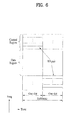
- Fig. 6 illustrates an exemplary structure of an uplink subframe.
- Fig. 7 illustrates an example of transmitting channel information, when the user equipment is signaled with information indicating ⁇ Cycle Period '5', Offset '1' ⁇ .
- Fig. 8 illustrates a system having a system band, which is configured of 16 RBs.
- Fig. 9 illustrates an example of transmitting both WB CQI and SB CQI, when the user equipment is signaled with information indicating ⁇ Cycle Period '5', Offset '1' ⁇ .
- Fig. 10 illustrates an example of performing communication under a multiple component carrier situation, wherein the communication example may correspond to an exemplary communication performed in an LTE system.
- Fig. 11 illustrates an exemplary method for extending frequency resource related to the exemplary embodiment of the present invention, wherein a downlink subframe is given as an example.
- Fig. 12 illustrates an exemplary method for extending frequency resource related to the exemplary embodiment of the present invention, wherein the example shows extra RBs being added to a component carrier.
- Fig. 13 illustrates a flow chart showing the process steps of an exemplary method for transmitting channel information via uplink according to an exemplary embodiment of the present invention.
- Fig. 14 illustrates an exemplary resource region, which is configured for reporting CQI, according to an exemplary embodiment of the present invention.
- Fig. 15 illustrates a flow chart showing the process steps of an exemplary method for transmitting channel information via uplink according to another exemplary embodiment of the present invention.
- Fig. 16 illustrates another exemplary resource region, which is configured for reporting CQI, according to an exemplary embodiment of the present invention.
- Fig. 17 illustrates an example of a signal for channel measurement being transmitted via uplink from a resource region, wherein the frequency resource is extended, according to an exemplary embodiment of the present invention.
- Fig. 18 illustrates an exemplary frequency bandwidth in which SRS transmission is performed from a resource region, wherein the frequency resource is extended, according to an exemplary embodiment of the present invention.
- Fig. 19 illustrates another example of a signal for channel measurement being transmitted via uplink from a resource region, wherein the frequency resource is extended, according to an exemplary embodiment of the present invention.
- Fig. 20 illustrates another exemplary frequency bandwidth in which SRS transmission is performed from a resource region, wherein the frequency resource is extended, according to an exemplary embodiment of the present invention.
- Fig. 21 illustrates yet another exemplary frequency bandwidth in which SRS transmission is performed from a resource region, wherein the frequency resource is extended, according to an exemplary embodiment of the present invention.
- Fig. 22 illustrates a block view showing the structures of an exemplary base station and an exemplary user equipment that can perform the embodiment of the present invention.
- the user terminal (or user equipment) universally refers to a mobile or fixed user-end device, such as a User Equipment (UE), a Mobile Station (MS), an Advanced Mobile Station (AMS), and so on.
- UE User Equipment
- MS Mobile Station
- AMS Advanced Mobile Station
- the base station universally refers to as an arbitrary node of a network end, which communicates with the user equipment, such as a Node B, an eNode B, a Base Station, an AP (Access Point), and so on.
- CDMA code division multiple access
- FDMA frequency division multiple access
- TDMA time division multiple access
- OFDMA orthogonal frequency division multiple access
- SC-FDMA single carrier frequency division multiple access
- CDMA may be implemented in radio technologies, such as UTRA (Universal Terrestrial Radio Access) or CDMA2000.
- TDMA may be implemented in radio technologies, such as GSM (Global System for Mobile communications)/GPRS (General Packet Radio Service)/EDGE (Enhanced Data Rates for GSM Evolution).
- GSM Global System for Mobile communications
- GPRS General Packet Radio Service
- EDGE Enhanced Data Rates for GSM Evolution
- OFDMA may be implemented in wireless (or radio) technologies, such as IEEE 802.11 (Wi-Fi), IEEE 802.16 (WiMAX), IEEE 802.20, E-UTRA (Evolved UTRA), and so on.
- UTRA is part of UMTS (Universal Mobile Telecommunications System).
- 3GPP (3rd Generation Partnership Project) LTE (long term evolution) is part of E-UMTS (Evolved UMTS) using E-UTRA.
- LTE-A Advanced corresponds to an evolution of 3GPP LTE.
- a user equipment may receive information from a base station via Downlink, and the user equipment may also transmit information via Uplink.
- Examples of the information being transmitted or received by the user equipment may include data and diverse control information. And, depending upon the different purposes of the information being transmitted or received by the user equipment, a variety of physical channels may exist.
- Fig. 2 illustrates an exemplary structure of a radio frame used in an LTE.
- a radio frame has the length of 10ms (327200*T S ) and includes ten(10) subframes each having the same size. Each subframe has the length of 1ms and includes of two (2) 0.5ms slots. Each slot has the length of 0.5ms (15360 ⁇ T s ).
- a slot includes a plurality of OFDM (Orthogonal frequency Division Multiplexing) (or SC-FDMA) symbols in the time domain and includes a plurality of Resource Blocks (RBs) in the frequency domain.
- OFDM Orthogonal frequency Division Multiplexing
- SC-FDMA Resource Blocks
- one resource block includes 12 subcarriers*7(6) OFDM (or SC-FDMA) symbols.
- Frame structure type-1 and -2 are respectively used in FDD and TDD.
- the frame structure type-2 includes two(2) Half Frames, and each Half Frame includes five(5) subframes, a Downlink Piloting Time Slot (DwPTS), a Guard Period (GP), and an Uplink Piloting Time Slot (UpPTS).
- DwPTS Downlink Piloting Time Slot
- GP Guard Period
- UpPTS Uplink Piloting Time Slot
- the above-described radio frame structure is merely exemplary. And, therefore, the number/length of the subframes, slots, or OFDM (or SC-FDMA) symbols may be diversely varied.
- Fig. 3 illustrates physical channels that are used in the 3GPP system and a general method for transmitting signals using such physical channels.
- the user equipment performs initial cell search such as synchronization with the base station, when it newly enters a cell or when the power is turned on (S310).
- the user equipment synchronizes with the base station by receiving a Primary Synchronization Channel (P-SCH) and a Secondary Synchronization Channel (S-SCH) from the base station, and then acquires information such as cell ID, and so on. Thereafter, the user equipment may acquire broadcast information within the cell by receiving a Physical Broadcast Channel from the base station.
- the user equipment may receive a Downlink Reference Signal (DL RS) so as to verify the downlink channel status.
- DL RS Downlink Reference Signal
- the corresponding user equipment may acquire more detailed system information by receiving a Physical Downlink Control Channel (PDCCH) and a Physical Downlink Control Channel (PDSCH) based upon the respective information carried in the PDCCH (S320).
- PDCCH Physical Downlink Control Channel
- PDSCH Physical Downlink Control Channel
- the user equipment may perform a Random Access Procedure (RACH) with respect to the base station (S330 to S360).
- RACH Random Access Procedure
- the user equipment may transmit a specific sequence to a preamble through a Physical Random Access Channel (PRACH) (S330 and S350), and may receive a response message respective to the preamble through the PDCCH and the PDSCH corresponding to the PDCCH (S340 and S360).
- PRACH Physical Random Access Channel
- a Contention Resolution Procedure may be additionally performed.
- the user equipment may perform PDCCH/PDSCH reception (S370) and Physical Uplink Shared Channel (PUSCH)/Physical Uplink Control Channel (PUCCH) transmission (S380), as general uplink/downlink signal transmission procedures.
- the control information which is transmitted by the user equipment to the base station or received by the user equipment from the base station via uplink, includes downlink/uplink ACK/NACK signals, a CQI (Channel Quality Indicator), a PMI (Precoding Matrix Index), an RI (Rank Indicator), and so on.
- the user equipment may transmit control information, such as the above-described CQI/PMI/RI through the PUSCH and/or the PUCCH.
- Fig. 4 illustrates an exemplary structure of a downlink subframe.
- one subframe includes two(2) slots in a time domain.
- a maximum of 3 OFDM symbols located at the beginning of a first slot correspond to a control region to which control channels are allocated.
- the remaining OFDM symbols correspond to a data region to which a Physical Downlink Shared Channel (PDSCH) is allocated.
- PDSCH Physical Downlink Shared Channel
- Examples of a downlink control channel used by a 3GPP LTE may include a PCFICH (Physical Control Format Indicator Channel), a PDCCH (Physical Downlink Control Channel), a PHICH (Physical Hybrid ARQ Indicator Channel), and so on.
- the PCFICH which is transmitted from the first OFDM symbol of the corresponding subframe, carries information related to the number of OFDM symbols (i.e., the size of the control region) used for the transmission of the control channels within the subframe.
- the control information being transmitted through the PDCCH may also be referred to as downlink control information (DCI).
- the DCI refers to uplink resource allocation information, downlink resource allocation information, uplink transmission power control commands respective to random user equipment groups, and so on.
- the PHICH carries an ACK (Acknowledgement)/NACK (Not-Acknowledgement) signal respective to an uplink HARQ (Hybrid Automatic Repeat Request). More specifically, the ACK/NACK signal respective to the uplink data transmitted by the user equipment is transmitted over (or through) the PHICH.
- the PDCCH which is a downlink physical channel
- the PDCCH may carry resource allocation and transmission format (also referred to as a downlink grant) of the PDSCH, resource allocation information (also referred to as an uplink grant) of the PUSCH, a group of transmission power control commands respective to each individual user equipment within a random user equipment group, activation of VoIP (Voice over Internet Protocol), and so on.
- Multiple PDCCHs may be transmitted with the control region, and the user equipment may monitor the multiple PDCCHs.
- the PDCCH is configured of one or an aggregation of several consecutive control channel elements (CCEs).
- the PDCCH which is configured of one or an aggregation of several consecutive control channel elements (CCEs) may be processed with subblock interleaving and then be transmitted through the control region.
- the CCE refers to a logical allocation unit, which is used for providing the PDCCH with a coding rate respective to a wireless channel condition (or status).
- the CCE corresponds to multiple resource element groups. Depending upon a correlation between the number of CCEs and the coding rate being provided by the CCEs, the PDCCH format and the number of available PDCCH bits may be decided.
- the control information that is being transmitted through the PDCCH is referred to as a downlink control information (DCI).
- DCI downlink control information
- Table 1 below shows the DCI with respect to the corresponding DCI format.
- DCI Format Description DCI format 0 used for the scheduling of PUSCH DCI format 1 used for the scheduling of one PDSCH codeword DCI format 1A used for the compact scheduling of one PDSCH codeword for the compact scheduling of one PDSCII and random access procedure initiated a PDCCH order DCI format 1B used for the compact scheduling of one PDSCH codeword with precoding information DCI format 1C used for very compact scheduling of one PDCH codeword DCI format 1D used for the compact scheduling of one PDSCH codeword with precoding and power offset information DCI format 2 for scheduling PDSCH to UEs configured in closed-loop spatial multiplexing mode DCI format 2A used for scheduling PDSCH to UEs configured in open-loop spatial multiplexing mode DCI format 3 used for the transmission of TPC commands for PUCCH and PUSCH with 2-bit power adjustments DCI format 3A used for the transmission of TPC commands for PUCCH and PUSCH with single bit power adjustments
- DCI format 0 indicates uplink resource allocation information
- DCI format 1 ⁇ 2 indicate downlink resource allocation information
- DCI format 3, 3A indicate an uplink TPC (transmit power control) command for random user equipment groups.
- Fig. 5 illustrates a downlink time-frequency resource grid structure used in the 3GPP LTE system.
- a downlink signal being transmitted from each slot may be illustrated as a resource grid, as shown in Fig. 5 , which is configured of N RB *N SC number of subcarriers and N symb number of OFDM symbols or SC-FDMA symbols.
- N RB represents a number of Resource Blocks (RBs)
- N SC represents a number of subcarriers configuring an RB
- N symb represents a number of OFDM symbols or SC-FDMA symbols included in a slot.
- the size of the N RB may vary in accordance with a bandwidth configured within a cell, and the size of the N RB should also satisfy the condition of N min ,RB ⁇ N RB ⁇ N max ,RB . .
- N min ,RB signifies the smallest bandwidth that can be supported by the wireless communication system
- N max ,RB signifies the largest bandwidth that can be supported by the wireless communication system.
- the number of OFDM symbols or SC-FDMA symbols included in a slot may vary depending upon the length of a Cyclic Prefix (CP) and an interval between subcarriers.
- CP Cyclic Prefix
- one resource grid may be defined for one antenna port.
- Each element within a resource grid respective to each antenna is referred to as a Resource Element (RE), and each element is uniquely identified by an index pair (k,1) within the respective slot.
- k has a value of any one of 0,....N RB *N SC -1
- 1 has a value of any one of 0,....,N symb -1.
- Fig. 6 illustrates an exemplary structure of an uplink subframe.
- an uplink subframe includes multiple slots (e.g., two(2) slots).
- the uplink subframe is divided into a data region and a control region within the frequency domain.
- the data region includes an uplink shared channel (PUSCH) and is used for transmitting data signals, such as voice, video, and so on.
- the control region includes an uplink control channel (PUCCH) and is used for transmitting control information.
- the PUCCH includes an RB pair located at each end portion of the data region in a frequency axis and hops at a slot boundary.
- the control information includes Hybrid Automatic Retransmit request (HARQ) ACK/NACK and channel information on the downlink (hereinafter referred to as downlink channel information or channel information).
- HARQ Hybrid Automatic Retransmit request
- the downlink channel information includes CQI, PMI, RI, and so on.
- the base station may use the downlink channel information received from each user equipment to decide adequate time/frequency resources, modulation method, coding rate, and so on, in order to transmit data to each user equipment.
- channel information includes CQI, PMI, RI, and so on. And, depending upon the transmission mode of each user equipment, all of the CQI, PMI, RI, and so on, or only a portion of the CQI, PMI, RI, and so on may be transmitted.
- periodic reporting A case when the channel information is transmitted periodically is referred to as periodic reporting, and a case when the channel information is transmitted only upon request made by the base station is referred to as aperiodic reporting.
- a request bit included in the uplink scheduling information delivered from the base station is transmitted to the user equipment. Thereafter, the user equipment delivers channel information, which is based upon its own transmission mode, to the base station through an uplink data channel (PUSCH).
- PUSCH uplink data channel
- a cycle period and an offset during the corresponding cycle period are signaled in subframe units through a higher layer signal for each user equipment by using a semi-static method.
- Each user equipment delivers channel information, which is based upon its own transmission mode, to the base station through an uplink control channel (PUCCH) in accordance with a decided cycle period.
- PUCCH uplink control channel
- the channel information is transmitted through the uplink data channel (PUSCH) along with the co-existing data.
- the base station may transmit transmission timing information, which is adequate for each user equipment, to the user equipments.
- the transmission timing information includes a cycle period for transmitting channel information, offset, and so on.
- the transmission timing information may be transmitted to each user equipment through a Radio Resource Control (RRC) message.
- RRC Radio Resource Control
- Fig. 7 to Fig. 9 respectively show examples of periodic reporting of channel information.
- the drawings are mainly focused on a case of transmitting downlink channel information (e.g., CQI, PMI, RI, and so on).
- downlink channel information e.g., CQI, PMI, RI, and so on
- uplink channel information e.g., SRS, and so on
- Fig. 7 illustrates an example of transmitting channel information, when the user equipment is signaled with information indicating ⁇ Cycle Period '5', Offset '1' ⁇ .
- the user equipment when information indicating that the cycle period is '5' and that the offset is '1' is received, the user equipment transmits channel information in units of 5 subframes with an offset of one subframe along an increasing direction of the subframe index starting from the 0 th subframe.
- the channel information is basically transmitted through PUCCH. However, if a PUSCH for transmitting data exists at the same time period, the channel information is transmitted through the PUSCH along with data.
- the subframe index is configured of a combination of a system frame information (n f ) and a slot index (n s , 0 ⁇ 19). Since a subframe is configured of 2 slots, the subframe index may be defined as 10*n f +floor(n s /2). Herein, floor() indicates a floor function.
- Fig. 8 illustrates a system having a system band, which is configured of 16 RBs.
- the system band is configured of two Bandwidth Parts (BP) (BP0, BP1), that each BP is configured of two subbands (SB) (SB0, SB1), that each SB is configured of 4 RBs.
- BP Bandwidth Part
- SB subbands
- the number of BPs and the size of each SB may vary depending upon the size of the system band.
- the number of SBs configuring each BP may vary depending upon the number of RBs, the number of BPs, and the SB size.
- the WB CQI and SB CQI are alternately transmitted.
- the PMI is also required to be transmitted in accordance with a PMI feedback type, the PMI information is transmitted along with the CQI information.
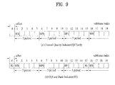
- Fig. 9 illustrates an example of transmitting both WB CQI and SB CQI, when the user equipment is signaled with information indicating ⁇ Cycle Period '5', Offset '1' ⁇ .
- the CQI may be transmitted only from a subframe corresponding to the signaled cycle period and offset.
- Fig. 9(a) illustrates an example wherein only the CQI is transmitted
- Fig. 9(b) illustrates an example wherein the CQI is transmitted along with a Rank Indicator (RI).
- the RI may be signaled from a higher layer (e.g., RRC layer) a combination of a particular multiple of the WB CQI transmission cycle period and the offset of the corresponding transmission cycle period.
- the offset of the RI is signaled as a value relative to the CQI offset.
- the RI when the offset of the CQI is '1', and when the offset of the RI is '0', the RI may have the same offset of the CQI.
- the value of the RI offset may be defined as 0 or a negative number. More specifically, it is assumed in Fig. 9(b) that, under the same environment as Fig. 9(a) , the transmission cycle period of the RI is one time the transmission cycle period of the WB CQI, and it is also assumed that the RI offset is equal to '-1' .
- the WB CQI When the transmission subframe of the WB CQI overlays with the transmission subframe of the RI, the WB CQI is dropped and the RI is transmitted.
- the LTE-A system adopts a carrier aggregation (or bandwidth aggregation) technology gathering a plurality of up-/downlink frequency blocks, so as to use a larger (or wider) up-/downlink bandwidth.
- Each frequency block is transmitted by using a Component Carrier (CC).
- CC Component Carrier
- the component carrier may signify a frequency block for carrier aggregation or a central carrier of the frequency block, and such definitions may be alternately used herein.
- Fig. 10 illustrates an example of performing communication under a multiple component carrier situation, which may correspond to the exemplary communication performing in an LTE-A system.
- 5 (five) 20MHz CCs may be gathered in each of the up-/downlink, so as to support a 100MHz bandwidth.
- the CCs may be adjacent or non-adjacent to one another in the frequency domain.
- Fig. 10 shows an example where the bandwidth of the uplink component carrier and the bandwidth of the downlink component carrier are identical to one another and are symmetrical to one another.
- the bandwidth of each component carrier may be decided independently.
- the bandwidth of the downlink component carrier may be configured as 5MHz (UL CC0) + 20MHz(UL CC1) + 20MHz(UL CC2) + 20MHz(UL CC3) + 5MHz(UL CC4).
- an asymmetrical carrier aggregation (or bandwidth aggregation), wherein the number of uplink component carriers and the number of downlink component carriers are different from one another, may be used.
- the asymmetrical carrier aggregation (or bandwidth aggregation) may be generated due to a limitation in the available frequency band, or may be artificially configured by network settings. For example, even if the overall system band is configured of N number of CCs, the frequency band that can be received by one specific terminal may be limited to M( ⁇ N) number of CCs.
- Various parameters respective to the carrier aggregation may be determined by using a cell-specific method, a UE group*-specific method, or a UE-specific method.
- Fig. 10 shows an example wherein the uplink signal and the downlink signal are transmitted through a component carrier mapped at a one-to-one (1:1) correspondence with the signal.
- the component carrier through which a signal is actually being transmitted may vary depending upon the network settings or the signal type. For example, when a scheduling command is transmitted via downlink through the DL CC1, the data transmission and reception respective to the scheduling command may be performed through a different DL CC.
- control information related to the DL CC may be transmitted via uplink through a specific UL CC (group) regardless of a mapping status.
- Downlink control information may also be similarly transmitted through a specific DL CC (group).
- An example of the method for extending the frequency resource may include a method of supplementing (or adding) a segment to a legacy resource region as an extended resource region or a method of adding extra RBs or additional RBs.
- the legacy resource region is used to be differentiated from the extended resource region.
- an example of the legacy resource region may include an LTE bandwidth.
- a segment or RBs corresponding to the extended resource region may be considered as a bandwidth that may be used by the LTE-A user equipments.
- a segment refers to a resource region that is added in order to perform data extension of a carrier, which is used in an LTE/LTE-A system, in accordance with a backward compatible method. And, accordingly, the segment may be defined as a resource region that is non-backward compatibly used with respect to the LTE-A user equipments. For example, when 30 RBs are allocated as the frequency resource, 25 RBs may be aggregated as a backward compatible carrier, and the remaining 5 RBs may be designated as a segment region that can only be used by the LTE-A user equipments.
- Fig. 11 illustrates an exemplary method for extending frequency resource related to the exemplary embodiment of the present invention, wherein a downlink subframe is given as an example.
- a segment that is only be used by the LTE-A user equipments may be additionally configured at each end of a downlink component carrier (CC), which may be compatibly used with respect to the convention LTE/LTE-A system.
- CC downlink component carrier
- the LTE user equipment may only recognize the B 0 MHz band (hereinafter referred to as an LTE band for simplicity). Therefore, control information and data may be transmitted in accordance with the LTE standard from the LTE band corresponding to the central region of the frequency bandwidth.
- the remaining regions (segment 1 and segment 2) excluding the LTE band may only be recognized by the LTE-A user equipments. More specifically, the LTE-A user equipment may use the overall carrier bandwidth B MHz.
- Each of the subbands being designated to a subframe may include an extended RB group, which is extended for the LTE-A user equipment.
- the base station When a user equipment newly enters a cell, or when the power of the user equipment is turned on, in order to allow the user equipment to perform initial cell search, such as performing synchronization with the base station, and in order to allow the user equipment to perform a random access procedure with respect to the base station, the base station transmits a synchronization signal, system information or paging information.
- a segment region is used for transmitting data information, which is transmitted only to an LTE-A user equipment, and a band region corresponds to the segment region corresponding to an extended carrier respective to a non stand-alone carrier.
- a stand-alone carrier corresponds to a carrier uniquely enabling the corresponding carrier to perform basic access, cell search, and system information transmission processes with respect to a user equipment within a random cell or base station or relay node based upon a definition of a physical channel and a physical signal each having the same format as an LTE Rel-8 carrier.
- the stand-alone carrier includes a backward compatible carrier and a non-backward compatible carrier. Therefore, the non stand-along carrier corresponds to a carrier that does not support the above-described procedure.
- a system overhead may be reduced.
- the usage rate of a channel bandwidth in an LTE system corresponds to 90%.
- a transmission bandwidth that may be configured within a channel bandwidth of 20 MHz may be supported to up to 100RB including the guard band.
- the region occupied by the guard band of the LTE increases. Therefore, when performing consecutive carrier aggregation, the number of guard bands between each CC may be reduced or removed, and the corresponding region may be applied and used as a resource extension region for an LTE-A user equipment.
- a frequency resource may be extended.
- Fig. 12 illustrates an exemplary method for extending frequency resource related to the exemplary embodiment of the present invention, wherein the example shows extra RBs being added to a component carrier.
- an LTE-A transmission bandwidth more extended than the LTE transmission bandwidth may be configured.
- the LTE user equipment may perform transmission and reception through a predetermined region of the CC, which corresponds to an RB allocated to the LTE transmission bandwidth. Meanwhile, by performing transmission and reception through an overall extended CC including LTE RBs and extra RBs, in case of performing consecutive carrier aggregation, the LTE-A user equipment may increase the efficiency in frequency usage.
- the LTE transmission bandwidth is configured of 100 RBs
- the remaining RBs excluding the 100 RBs correspond to extra RBs that are added for the LTE-A.
- RBs which are used for data transmission with respect to an LTE-A user equipment, may be referred to as extra RBs, additional RBs, or non-compatible RBs. And, each term may be used to signify the same meaning.
- the present invention proposes a method for transmitting controlling information with respect to a downlink and a method for transmitting a reference signal in order to perform uplink channel measurement.
- the downlink channel information e.g., CQI, PMI, RI, and so on
- the CQI will be given as an example.
- a Sounding Reference Signal (SRS) for performing uplink measurement will also be given as an example for describing the present invention.
- SRS Sounding Reference Signal
- channel information includes CQI, PMI (Precoding Matrix Indicator), RI (Rank Indicator), and so on.
- CQI Precoding Matrix Indicator
- PMI Precoding Matrix Indicator
- RI Rank Indicator
- each user equipment may transmit the control channel, such as CQI, PMI, RI, and so on, through a PUSCH or a PUCCH.
- the CQI reporting method used by the user equipment may be controlled by the base station. And, the CQI reporting method may be divided into periodic reporting, which transmits channel information periodically, and aperiodic reporting, which transmits channel information only upon request made by the base station.
- the base station By configuring a CQI request bit from an uplink resource grant delivered from the base station through the PDCCH, the base station schedules the aperiodic CQI reporting method. Each user equipment uses the RRC signaling, which is transmitted from the base station, so as to configure the CQI reporting type.
- the CQI reporting type existing in the LTE system may first of all be divided into a wideband (WB) CQI, which reports a single CQI value respective to the overall system bandwidth based upon the feedback type, and a subband (SB) CQI, which reports the CQI for each subband divided from the system bandwidth.
- WB wideband
- SB subband
- the SB CQI may be divided into an eNB-configured subband feedback, which reports CQI by using a subband configured in the base station (eNB), and a UE-selected subband feedback, which report CQI through a subband selected by each user equipment.
- the user equipment may not only report the WB CQI respective to the overall system bandwidth but may also report the CQI respective to each subband.
- the subband size (k) corresponds to a function of the system bandwidth, as shown in Table 3 below.
- Table 2 shows a comparison between a system bandwidth and a subband size in the eNB-configured aperiodic reporting method.
- Table 2 [Table 2] System Bandwidth(RBs) Subband size(k RBs) 6-7 Wideband CQI only 8-10 4 11-26 4 27-63 6 64-110 8
- the user equipment may select a number (M) of preferred subbands for each subband size (k) within the overall system bandwidth.
- the user equipment reports one WB CQI and one CQI, which reflects an average quality of M number of selected subbands, to the base station.
- Table 3 shows a subband size (k) respective to the system bandwidth and a number (M) of preferred subbands in the UE-selected aperiodic reporting method.
- Table 3 [Table 3] System Bandwidth(RBs) Subband size(k RBs) Number of preferred Subbands(M) 6-7 Wideband CQI only Wideband CQI only 8-10 2 1 11-26 2 3 27-63 3 5 64-110 4 6
- a cycle period and an offset during the corresponding cycle period are signaled in subframe units through a higher layer signal for each user equipment by using a semi-static method.
- Each user equipment delivers a CQI, which is based upon its own transmission mode, to the base station through an uplink control channel (PUCCH) in accordance with a decided cycle period.
- PUCCH uplink control channel
- the channel information is transmitted through the uplink data channel (PUSCH) along with the co-existing data.
- the base station may transmit transmission timing information, which is adequate for each user equipment, to the user equipments.
- the transmission timing information includes a cycle period for transmitting channel information, offset, and so on.
- the transmission timing information may be transmitted to each user equipment through a RRC message.
- the CQI reporting type existing in the LTE system may first of all be divided into a wideband (WB) CQI, which reports a single CQI value respective to the overall system bandwidth based upon the feedback type, and a subband (SB) CQI, which reports the CQI for each subband divided from the system bandwidth.
- WB wideband
- SB subband
- the SB CQI may be divided into an eNB-configured subband feedback, which reports CQI by using a subband configured in the base station (eNB), and a UE-selected subband feedback, which report CQI through a subband selected by each user equipment.
- the reporting cycle period may be configured as ⁇ 2,5,10,16,20,32,40,64,80,160 ⁇ ms or as 'OFF', in case of the FDD.
- the wideband feedback mode is similar to that, which is transmitted through the PUSCH, whereas the UE-selected subband CQI reporting is differentiated as a transmission method through the PUCCH.
- the overall number N of the subbands may be divided into J number of partial bandwidths, which are referred to as bandwidth parts (BW parts). As shown in Table 5 below, the value of J may vary in accordance with the system bandwidth.
- a CQI value is calculated with respect to a specifically selected subband, which is selected from each BW part, along with a corresponding subframe index. Then, the calculated CQI value is reported.
- Table 4 [Table 4] System Bandwidth(RBs) Subband size(k RBs) Number of bandwidth parts(J) 6-7 Wideband CQI only 1 8-10 4 1 11-26 4 2 27-63 6 3 64-110 8 4
- the subband CQI report is performed in resource units configured of multiple RBs.
- the present invention may propose a method wherein uplink signaling configuration information respective to the extended resource region uses configuration information related to the conventional resource region or a method of transmitting separate configuration information with respect to the extended resource region.
- the LTE band will be given as an example of the legacy resource region, and extra RBs will be given as an example of the extended resource region.
- Fig. 13 illustrates a flow chart showing the process steps of an exemplary method for transmitting channel information via uplink according to an exemplary embodiment of the present invention.
- the user equipment receives CQI configuration information related to a system basic band or a legacy band (hereinafter referred to as an LTE band) from the base station (S1301).
- the CQI configuration information related to the LTE band is decided regardless of the extended frequency resource (hereinafter referred to as an extra band).
- the CQI configuration information may include at least any one of CQI report cycle period/offset, subband size, a number of bandwidth parts, and a number of preferred subbands.
- the user equipment uses channel information acquired by performing channel measurement on an LTE band and also uses the CQI configuration information related to the LTE band, which is received during the previous process step, so as to decide the LTE frequency band being the CQI reporting target (S1302).
- CQI related to downlink channel quality may be acquired as the channel information, and the user equipment may use a UE-selected periodic CQI reporting method as the CQI reporting method.
- the LTE band may be divided into a predetermined number of BW parts (e.g., 4), and each BW part may include at least one or more subbands.
- the CQIs acquired in each subband are compared to one another for each BW part in order to identify the subframe indicating the most optimal CQI.
- the optimal CQI is decided as the LTE frequency band, which is the CQI reporting target, and the respective channel information may be transmitted.
- the user equipment determines whether or not the optimal CQI that is decided as the LTE frequency band being the CQI reporting target, in the previous process step S1302 is adjacent to an extra band (S1303).
- the extra band may correspond to a segment or an extra RB being added to the LTE frequency band, or the extra band may correspond to an extra RB being used as a band specifically used for signal transmission, among the guard bands of the LTE frequency band.
- the extra band is included in the corresponding LTE frequency band, and the corresponding CQI is transmitted to the base station (S1304).
- the CQI related to the LTE frequency band is included in the CQI being transmitted to the base station.
- the LTE frequency band is not adjacent to the extra band, only the channel information respective to the corresponding LTE frequency band is transmitted to the base station (S1305).
- the user equipment may selectively (or optionally) transmit channel information on the extended resource region. And, when transmitting the channel information respective to the extended resource region, by including the corresponding channel information in an adjacent LTE frequency band and then transmitted the corresponding LTE frequency band, the number of subbands and the number of BW parts included in the overall LTE frequency band may also be maintained. Also, the channel information transmission method shown in Fig. 13 may also be applied to other types of downlink channel information (e.g., PMI or RI).
- PMI downlink channel information
- Fig. 14 illustrates an exemplary resource region, which is configured for reporting CQI, according to an exemplary embodiment of the present invention. More specifically, the example presented herein corresponds to a case when the UE-selected periodic CQI reporting method is used as the uplink CQI transmission method.
- the LTE bandwidth (or LTE band) is configured of 100 RBs and that a subband is configured in units of 8 RBs. At this point, any one of the subbands is configured of 4 RBs. Furthermore, it is also assumed that a total of 8 RBs is added to the extra RB, i.e., 4 RBs are added to each end of the LTE bandwidth, in order to extend the frequency resource.
- the base station may generate configuration information on the 100 RBs solely based upon the LTE bandwidth, and, then, the base station may transmit the generated configuration information to the user equipment.
- the user equipment may apply the received configuration information related to the LTE bandwidth not only to the LTE bandwidth but also to the added extra RBs.
- the LTE bandwidth is divided into a total of 4 BW parts including at least one or more subbands. And, in each BW part, a comparison process is performed on the CQI for each subband, so that a specific subband related to the CQI reporting can be decided.
- the base station may use the configuration information on the LTE bandwidth so as to configure an extended subband having a format of adding extra RBs adjacent to each subband. Accordingly, while the total number of subbands within the LTE bandwidth is maintained, the subbands (subband #1, subband #3) located at each end of the LTE bandwidth may be respectively extended from 8RBs and 4RBs to 12RBs and 8RBs.
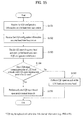
- Fig. 15 illustrates a flow chart showing the process steps of an exemplary method for transmitting channel information via uplink according to another exemplary embodiment of the present invention.
- the CQI is given as an example of the channel information.
- the base station may independently configure first configuration information enabling the user equipment to transmit downlink channel information on an LTE band, which is a legacy resource region, to the base station and second configuration information enabling the user equipment to transmit downlink channel information on an extended resource region to the base station.
- the user equipment may receive a first CQI configuration information on a system basic band (hereinafter referred to as an LTE band) and a second CQI configuration information on an extra band (or LTE-A band) via separate signaling (S1501 and S1502).
- LTE band system basic band
- extra band or LTE-A band
- the time order of the process step of the user equipment for receiving each configuration information may vary from the flow chart shown in Fig. 15 .
- the user equipment may receive the first CQI configuration information on the LTE band from the base station, and then the user equipment may use the received first CQI configuration information to deduce the second CQI configuration information on the extra band, or the user equipment may use offset information so as to indirectly acquire the second CQI configuration information on the extra band.
- each configuration information may include at least any one of CQI report cycle period/offset, subband size, a number of bandwidth parts, and a number of preferred subbands.
- the user equipment performs channel measurement on the LTE band and the extra band, and, then, the user equipment respectively applies the CQI configuration information received during the previous process step so as to decide the CQI reporting frequency band and cycle period (S1503).
- the CQI reporting frequency band and cycle period S1503
- the entire LTE frequency band is divided into a plurality of BW parts, and a specific LTE frequency band indicating an optimal CQI for each BW part.
- the extra band is configured of extra RBs, and the user equipment configures a separate CQI respective to the extra band.
- each of the CQI of the LTE frequency band and the CQI of the extra band is transmitted in accordance with the respective CQI transmission cycle periods, which are included in each of the first CQI configuration information and the second CQI configuration information, which are received during the previous process step. However, in this case, it is determined whether or not the transmission points of both CQIs coincide (or match) with one another (S1504).
- the CQI of the LTE frequency band and the CQI of the extra band are respectively transmitted in accordance with each CQI transmission cycle period included the first CQI configuration information and the second CQI configuration information, which are received during the previous process step (S1505).
- a signal interference may occur.
- configurations are made so that only one of the CQIs is transmitted in accordance with a predetermined drop rule (S1506).
- the drop rule for the CQI reporting method is first configured by the base station, and the same rule may be applied to the user equipment or the base station when performing transmission to the user equipment or when setting up system configurations.
- An example of such dropping rule is shown in Table 5.
- CQI LTE corresponds to a CQI value respective to a channel measurement in an LTE Rel-8 band, which is a legacy resource region
- CQI ADD corresponds to a CQI value respective to a channel measurement in an extra band, which is an extended resource region.
- the user equipment may compare the CQI LTE and the CQI ADD , so as to transmit the CQI having the better characteristics. However, in this case, the user equipment may also transmit separate identification information indicating whether the CQI corresponds to the CQI of the LTE Rel-8 band or to the CQI of the extra band.
- the channel information transmission method shown Fig. 15 may also be applied to another downlink channel information (e.g., PMI or RI).
- another downlink channel information e.g., PMI or RI.
- Fig. 16 illustrates another exemplary resource region, which is configured for reporting CQI, according to an exemplary embodiment of the present invention. More specifically, as a case of using the UE-selected periodic CQI reporting method, Fig. 16 shows an exemplary uplink CQI reporting method applying the CQI reporting method described in Fig. 15 .
- the LTE bandwidth is configured of 100 RBs, and a subband is configured in units of 8 RBs. And, the last 4RBs configure a separate subband. 4 RBs may be added to each end of the LTE bandwidth, i.e., a total of 8 extra RBs may be added to the LTE bandwidth in order to extend the frequency resource.
- the CQI respective to the subband of the LTE bandwidth and the CQI respective to the extra subband are separately transmitted via uplink.
- the extra subband is configured of extra RBs being added to each end of the LTE bandwidth.
- the present invention proposes an uplink signaling method related to a Sounding Reference Signal (SRS) transmission.
- SRS Sounding Reference Signal
- the LTE-A system may use a greater number of antennae and a new network element, such as a relay.
- the LTE-A system including such new element should be capable of supporting a connection between the LTE-A system and an LTE-A user equipment.
- the LTE-A system should be capable of maintaining the performance of a legacy system, such as the convention LTE system.
- the SRS may be given as an example of a signal that may be used by the base station for estimating a channel status from each user equipment to the base station.
- the SRS is transmitted through a section including an SC-FDMA symbol, which is located at an end portion of the uplink subframe within a time axis, and a data transmission band within the frequency domain.
- Sounding reference signals respective to multiple user equipments that are being transmitted to the last SC-FDMA of the same uplink subframe may be differentiated from one another depending upon the frequency position/sequence.
- a cycle period for transmitting the SRS by using a semi-static method through a higher layer signal for each user equipment and an offset respective to the corresponding cycle period may be signaled in subframe units.
- the SRS may be transmitted through an entire band or subband. And, when the SRS is transmitted through a subband, frequency band hopping may be performed during the SRS transmission.
- Channel information related to downlink or configuration information for transmitting the SRS may be allocated from the base station to the user equipment via Cell-specific and/or UE-specific RRC signaling.
- a maximum of 4 SRS bandwidths may be simultaneously supported in the LTE in accordance with the system bandwidth.
- 8 sets each configured of 4 SRS bandwidths may be defined with respect to each available system bandwidth.
- the base station may designate an SRS bandwidth, which the base station wishes to use, through a 3-bit cell-specific parameter (e.g., 'srsBandwidthConfiguration'), which is transmitted via RRC signaling.
- a maximum number SRS bandwidths may be diversely configured within a range that is not included in a PUCCH, which is located in the boundary region of the system bandwidth.
- An example of the 8 sets each configured of 4 SRS bandwidths is shown in Table 6.
- Table 6 shows an example of an SRS bandwidth configuration respective to the system bandwidth.
- a system bandwidth is configured of a total of 80 ⁇ 110 RBs.
- the vertical axis shows 8 SRS sets each configured of 4 SRS bandwidths.
- the horizontal axis indicates the number of RBs being allocated to the SRS transmission bandwidth for each index of the bandwidth being allocated for SRS transmission, and the horizontal axis also indicates a number of SRS bandwidths having the same size.
- the SRS bandwidth having the shortest length is configured of 4 RBs.
- the shortest SRS bandwidth being configured of 4 RBs is used for providing high quality channel information from a user equipment with limited power.
- the SRS bandwidth may be configured to have a tree structure, so that each SRS bandwidth can be multiplied by one another.
- the present invention proposes a method of simultaneously transmitting SRS of a legacy resource region and SRS of an extended resource region via uplink SRS transmission in a frequency resource extension, or a method of independently transmitting each SRS with a predetermined time interval.
- Fig. 17 illustrates an example of a signal for channel measurement being transmitted via uplink from a resource region, wherein the frequency resource is extended, according to an exemplary embodiment of the present invention.
- a sounding reference signal SRS
- SRS sounding reference signal
- the user equipment receives SRS configuration information of a system basic band (hereinafter referred to as an LTE band) from the base station (S1701).
- the SRS configuration information of the LTE band is decided regardless of the extended frequency resource (hereinafter referred to as an extra band).
- the SRS configuration information may include at least any one of SRS transmission cycle period/offset, SRS BW configuration parameter, SRS BW, and SRS hopping BW.
- the user equipment applies the SRS configuration inofmration of the LTE band, so as to decide the LTE frequency band being the SRS transmission target (S1702).
- the user equipment determines whether or not the decided LTE frequency band is adjacent to an extra band (S1703).
- the extra band refers to a band configured of extra RBs added to the LTE band.
- the SRS of the corresponding LTE frequency band and the SRS of the extra band are independently configured and transmitted simultaneously (S1704).
- the SRS symbol of the extra RB is generated by being differentiated from the SRS symbol respective to the SRS bandwidth of the LTE band.
- the SRS is transmitted only from the corresponding LTE frequency band (S1705).
- FIG. 18 An example of the SRS transmission frequency band according to the above-described exemplary embodiment of the present invention is shown in Fig. 18 .
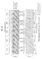
- Fig. 18 illustrates an exemplary frequency bandwidth in which SRS transmission is performed from a resource region, wherein the frequency resource is extended, according to an exemplary embodiment of the present invention.
- 100 RBs are allocated to the LTE bandwidth, which corresponds to the legacy resource region, and that 4RBs are added to both ends of the LTE bandwidth.
- 96 RBs are allocated in relation to SRS transmission hopping, and, within the entire system bandwidth, 4RBs are not used for SRS transmission.
- the user equipment may apply the SRS configuration information of the LTE bandwidth, which is transmitted from the base station, to the 4 RBs extended at each end of the LTE bandwidth.
- the SRS configuration information of the SRS transmission bandwidth which is allocated with 24 RBs of index 2
- the user equipment may additionally transmit SRS of the extra 4 RBs (1802) at an SRS transmission point of the SRS transmission bandwidth (1801) most adjacent to the extra RBs.
- the SRS symbols respective to the extended 4RBs (1802) may be configured to be separated from the SRS symbols respective to the SRS bandwidth (1801) of the 24 RBs.
- the SRS bandwidths (1803) that are not adjacent to the Extra RBs only the SRSs respective to the corresponding bandwidths are transmitted.
- the base station differentiates the legacy resource region (e.g., LTE band) from the extended resource region (e.g., segment or extra RB), and, then, the base station transmits configuration information related to the uplink SRS transmission (e.g., SRS transmission cycle period/offset, SRS BW configuration parameter, SRS BW, and SRS hopping BW) of each resource region to each user equipment.
- legacy resource region e.g., LTE band
- the extended resource region e.g., segment or extra RB
- configuration information related to the uplink SRS transmission e.g., SRS transmission cycle period/offset, SRS BW configuration parameter, SRS BW, and SRS hopping BW
- each user equipment generates a separate SRS, depending upon the SRS configuration information, which is allocated to the legacy resource region and the extended resource region, thereby transmitting the generated SRS to the base station via uplink.
- Fig. 19 illustrates another example of a signal for channel measurement being transmitted via uplink from a resource region, wherein the frequency resource is extended, according to an exemplary embodiment of the present invention.
- a sounding reference signal SRS
- SRS sounding reference signal
- the user equipment receives first SRS configuration information related to the legacy resource region (hereinafter referred to as an LTE band) and second SRS configuration information related to the extended resource region (hereinafter referred to as an extra band) from the base station via separate signaling (S1901 and S1902).
- LTE band legacy resource region
- extra band extended resource region
- the user equipment decides a predetermined frequency band for transmitting the SRS from the entire LTE frequency band, based upon the first SRS configuration information, and, then the user equipment decides the respective transmission cycle period. Thereafter, the user equipment configures an SRS respective to the extra band based upon the second SRS configuration information in accordance with a predetermined transmission cycle period (S1903).
- the base station separately configures configuration information related to SRS transmission respective to the LTE frequency band and the extra band, there may occur a case when the transmission points coincide, regardless of whether or not the SRS transmission cycle period are identical to one another. And, accordingly, interference may occur between SRS signals, which are transmitted at the same transmission point.
- the user equipment first determines whether or not the SRS transmission point of the LTE band coincides with the SRS transmission point of the extra band (S1904). Thereafter, in case the two SRS transmission points do not coincide, the SRSs respective to the LTE band and the extra band may be transmitted in accordance with the respective transmission cycle period (S1905).
- the system may be configured so that any one of the two SRSs can be transmitted in accordance with a predetermined dropping rule (S1906).
- the dropping rule related to the SRS transmission is first configured by the base station, and the same rule may be applied to the user equipment or the base station when performing transmission to the user equipment or when setting up system configurations.
- An example of such dropping rule is shown in Table 7.
- Table 7 Dropping Rule When the transmission point of SRS LTE coincides with the transmission point of SRS ADD 1) SRS ADD is always dropped. 2) A comparison is first made between bandwiths being the respective measurement objects of SRS LTE and SRS ADD . Then, the SRS of the smallest bandwith is dropped. 3) A comparison is made between transmission cycle periods of SRS LTE and SRS ADD . Then, the SRS having the smallest transmission cycle period is dropped. 4) When the transmission cycle periods of SRS LTE and SRS ADD are identical to one another, any one of the two SRSs is alternately dropped at each transmission point. For example, when SRS LTE is dropped in the 1 st subframe, SRS ADD is dropped in the 2 nd subframe, and SRS LTE is dropped once again in the 3 rd subframe. This dropping method is repeatedly performed.
- SRS LTE corresponds to an SRS transmission from an LTE Rel-8 band, which corresponds to an example of the legacy resource region
- SRS ADD corresponds to an SRS transmission from an extra band, which is configured of extra RBs.
- the user equipment may compare the SRS LTE and the SRS ADD , based upon the uplink channel status, so as to transmit the SRS having the better characteristics. However, in this case, the user equipment may also transmit separate identification information indicating whether the CQI corresponds to the CQI of the LTE Rel-8 band or to the CQI of the extra band.
- Fig. 20 and Fig. 2220 illustrate other exemplary frequency bandwidths in which SRS transmission is performed from a resource region, wherein the frequency resource is extended, according to an exemplary embodiment of the present invention.
- 100 RBs are allocated to the LTE bandwidth, which corresponds to the legacy resource region, and 96 RBs are allocated to the SRS hopping bandwidth.
- SRS bandwidth it is assumed that, among the 8 SRS bandwidth sets, shown in Table 8, an SRS bandwidth being configured of 96 RBs, 48 RBs, 24 RBs, and 4 RBs, based upon the SRS bandwidth set of index 0, is being allocated.
- the base station configures SRS configuration information related to the LTE bandwidth (SRS BW configuration #1) and SRS configuration information related to the extended resource region (SRS BW configuration #2), and, then, the base station transmits the configured SRS configuration information to the user equipment via separate signaling. Therefore, the SRS transmission cycle period/offset value of each SRS respective to the LTE bandwidth and the extended resource region may be differently configured. Accordingly, the user equipment transmits the SRS via uplink, in accordance with the respective transmission cycle period, which is included in the SRS configuration information for the LTE bandwidth and the SRS configuration information for the extra RB.
- Fig. 20 shows an example of a case when inter-signal contention does not occur, due to a non-coincidence between the SRS transmission cycle period of an SRS bandwidth belonging to 24 RBs and the SRS transmission point of the extra RBs.
- the user equipment may drop any one of the SRSs in accordance with the predetermined dropping rule shown in Table 7.
- a case of dropping the SRS having the shortest transmission, in accordance with the dropping rule may be configured as case 1, and, a case of always dropping the extra RB may be configured as case 2.
- the user equipment may perform subband CQI reporting and SRS transmission by using configuration information related to an uplink signal transmission from a legacy system over an extended frequency resource, or in accordance with configuration information, which is configured to be differentiated from the legacy configuration information.
- Fig. 22 illustrates a block view showing the structures of an exemplary base station and an exemplary user equipment that can perform the embodiment of the present invention.
- the user equipment may operate as a transmission device in an uplink and may operate as a reception device in a downlink.
- the base station may operate as a reception device in an uplink and may operate as a transmission device in an uplink. More specifically, the user equipment and the base station may each include a transmission device and a reception device for transmitting information or data.
- Each of the transmission device and the reception device may include a processor, a module, a part and/or means each configured to perform the exemplary embodiments of the present invention.
- the transmission device and the reception device may include a module (means) configured to encrypt a message, a module configured to translate an encrypted message, an antennae configured to transmit and receive a message, and so on.
- the left side represents the structure of the transmission device, which indicates a base station
- the right side represents the structure of the reception device, which indicates a user equipment accessing a cell that is serviced by the base station.
- Each of the transmission device and the reception device may include an antenna (2201, 2202), a reception module (2210, 2220), a processor (2230, 2240), a transmission module (2250, 2260), and a memory (2270, 2280).
- the antenna (2201, 2202) is configured of a receiving antenna, which performs the functions of receiving a radio signal from an outside source and delivering the received signal to the reception module (2210, 2220), and a transmitting antenna, which performs the function of transmitting a signal generated from the transmission module (2250, 2260) to the outside source.
- a multiple antenna (MIMO) function is supported, at least 2 or more antennae (2201, 2202) may be provided herein.
- the reception module (2210, 2220) performs decoding and demodulation on the radio signal, which is received from the outside source through the antenna, so as to recover the received radio signal to an original data format, thereby delivering the processed data to the processor (2230, 2240).
- the reception module and antennae may also be illustrated as a receiving unit configured to receive radio signals.
- the processor (2230, 2240) generally controls the overall operations of the transmission device or the reception device. More specifically, a controller function for performing the above-described exemplary embodiments of the present invention, a MAC (Medium Access Control) frame variable control function based upon service characteristics and frequency environment (or condition), a Hand Over function, and authentication and encoding (or encryption) functions may be performed.
- a controller function for performing the above-described exemplary embodiments of the present invention a MAC (Medium Access Control) frame variable control function based upon service characteristics and frequency environment (or condition), a Hand Over function, and authentication and encoding (or encryption) functions may be performed.
- MAC Medium Access Control
- the transmission module (2250, 2260) may perform predetermined coding and modulation processes on data, which are scheduled by the processor (2230, 2240) and to be transmitted to the outside source, thereby delivering the processed data to the antenna.
- the transmission module and antennae may also be illustrated as a transmitting unit configured to transmit radio signals.
- a program for processing and controlling the processor (2230, 2240) may be stored in the memory (2270, 2280).
- the memory (2270, 2280) may also perform functions for temporarily storing input/output data (in case of a mobile user equipment, uplink grant (UL Grant) allocated from the base station, system information, station identifier (STID), flow identifier (FID)), operation time, and so on.
- UL Grant uplink grant
- TDD station identifier
- FID flow identifier
- the memory (2270, 2280) may include at least one type of storage means, such as a flash memory type, a hard-disk type, a multimedia card micro type, a card-type memory (e.g., SD or XD memory, etc.), a Random Access Memory (RAM), a SRAM (Static Random Access Memory), a Read-Only Memory (ROM), an EEPROM (Electrically Erasable Programmable Read-Only Memory), a PROM (Programmable Read-Only Memory), a magnetic memory, a magnetic disk, and an optical disk.
- a flash memory type such as a flash memory type, a hard-disk type, a multimedia card micro type, a card-type memory (e.g., SD or XD memory, etc.), a Random Access Memory (RAM), a SRAM (Static Random Access Memory), a Read-Only Memory (ROM), an EEPROM (Electrically Erasable Programmable Read-Only Memory), a PROM (Programmable Read-
- the processor (2230) of the transmitting device performs overall control operations of the base station. And, the processor (2230) of the transmitting device may generate configuration information related to the CQI or SRS, which is transmitted via uplink from the legacy resource region in accordance with the above-described embodiments of the present invention, as shown in Fig. 13 to Fig. 21 . Additionally, the processor (2230) of the transmitting device may also generate configuration information related to the CQI or SRS from the extended resource region.
- the CQI configuration information may correspond to information related to uplink signaling including CQI report cycle period/offset, subband size, a number of bandwidth parts, and a number of preferred subbands.
- the SRS configuration information may include information related to SRS transmission cycle periad/offset, SRS BW configuration parameter, SRS BW, and SRS hopping BW.
- the processor (2230) of the transmitting device configures a separate CQI or SRS configuration information with respect to the legacy resource region and the extended resource region
- the CQI report cycle period/offset value or the SRS transmission cycle period/offset value may be configured to have the same value.
- the receiving system receiving the configuration information may transmit the CQI or SRS at the same time point, or a problem of inter-signal contention may occur. Therefore, when configuring a separate CQI or SRS configuration information with respect to the extended resource region, the processor (2230) of the transmitting device may decide a predetermined dropping rule for preventing contention with the CQI or SRS of the legacy resource region. Thereafter, the processor (2230) of the transmitting device may transmit the decided dropping rule to the receiving device.
- the processor (2230) of the transmitting device may select a channel that is to be used based upon an uplink CQI, which is transmitted from the transmission module (2260) of the receiving device, or the processor (2230) of the transmitting device may receive an uplink SRS, so as to measure the quality of the corresponding channel.
- the processor (2240) of the receiving device performs overall control operations of the user equipment, and the processor (2240) of the receiving device may be allocated with resources of a predetermined region from the transmitting device.
- the allocated resource region may include the legacy resource region as well as the extended resource region (e.g., segment or extra RB).
- the receiving device receives configuration information related to the CQI or SRS transmission respective to the legacy resource region and/or the extended resource region from the transmitting device, and the receiving device may transmit the respective CQI or SRS via uplink.
- the processor (2240) of the receiving device may apply the CQI or SRS configuration information of the legacy resource region to the CQI or SRS transmission of the extended resource region, or the processor (2240) of the receiving device may apply CQI or SRS configuration information of the extended resource region, which is received via separate signaling, so as to transmit a signal.
- a predetermined dropping rule e.g., Table 5 or Table 7
- Table 5 or Table 7 which is predetermined or transmitted from the base station
- the present invention is not intended to limit the present invention to the embodiments presented herein. Instead, it is intended that the present invention grants a broadest range matching the principles and new characteristics disclosed herein.
- the exemplary embodiment of the present invention may be applied in diverse radio access systems.
- the diverse radio access systems may include 3GPP (3rd Generation Partnership Project), 3GPP2, and/or IEEE 802.xx (Institute of Electrical and Electronic Engineers 802) systems.
- the exemplary embodiments of the present invention may also be applied to all technical fields adopting the diverse radio access systems.
Landscapes
- Engineering & Computer Science (AREA)
- Signal Processing (AREA)
- Computer Networks & Wireless Communication (AREA)
- Mobile Radio Communication Systems (AREA)
Applications Claiming Priority (3)
| Application Number | Priority Date | Filing Date | Title |
|---|---|---|---|
| US22895209P | 2009-07-27 | 2009-07-27 | |
| KR1020100071839A KR101684969B1 (ko) | 2009-07-27 | 2010-07-26 | 제어 정보를 전송하는 방법 및 이를 위한 장치 |
| PCT/KR2010/004910 WO2011013977A2 (ko) | 2009-07-27 | 2010-07-27 | 제어 정보를 전송하는 방법 및 이를 위한 장치 |
Publications (2)
| Publication Number | Publication Date |
|---|---|
| EP2461504A2 true EP2461504A2 (de) | 2012-06-06 |
| EP2461504A4 EP2461504A4 (de) | 2016-08-17 |
Family
ID=43771727
Family Applications (1)
| Application Number | Title | Priority Date | Filing Date |
|---|---|---|---|
| EP10804690.5A Withdrawn EP2461504A4 (de) | 2009-07-27 | 2010-07-27 | Verfahren zur übertragung von steuerinformationen und vorrichtung dafür |
Country Status (4)
| Country | Link |
|---|---|
| US (1) | US8724574B2 (de) |
| EP (1) | EP2461504A4 (de) |
| KR (1) | KR101684969B1 (de) |
| WO (1) | WO2011013977A2 (de) |
Cited By (1)
| Publication number | Priority date | Publication date | Assignee | Title |
|---|---|---|---|---|
| CN105099603A (zh) * | 2014-04-28 | 2015-11-25 | 北京三星通信技术研究有限公司 | 一种信道状态信息的汇报方法及装置 |
Families Citing this family (48)
| Publication number | Priority date | Publication date | Assignee | Title |
|---|---|---|---|---|
| US9673952B2 (en) | 2009-04-10 | 2017-06-06 | Qualcomm Inc. | Method and apparatus for supporting user equipments on different system bandwidths |
| CN102484797A (zh) * | 2009-09-18 | 2012-05-30 | 索尼公司 | 中继站、中继方法和无线通信设备 |
| JP5515559B2 (ja) * | 2009-09-25 | 2014-06-11 | ソニー株式会社 | 通信システム、基地局、および通信装置 |
| US20110176519A1 (en) * | 2009-11-17 | 2011-07-21 | Pavan Kumar Vitthaladevuni | Signalling of Multiple-User Multiple-Input and Multiple-Output Transmissions in High-Speed Packet Access Systems |
| US9276710B2 (en) * | 2009-12-21 | 2016-03-01 | Qualcomm Incorporated | Method and apparatus for resource allocation with carrier extension |
| US8614981B2 (en) * | 2010-01-29 | 2013-12-24 | Qualcomm Incorporated | Reporting of channel information to support coordinated multi-point data transmission |
| KR101454737B1 (ko) * | 2010-03-25 | 2014-10-27 | 노키아 솔루션스 앤드 네트웍스 오와이 | 채널 정보의 시그널링 |
| BR112012025034B1 (pt) * | 2010-03-31 | 2022-02-01 | Huawei Technologies Co., Ltd | Método de relatório de qualidade de canal de enlace descendente aperiódico, meio de armazenamento legível por computador que armazena instruções, e aparelho de um sistema de comunicação via rádio utilizando agregação de portadora |
| CN102238616B (zh) * | 2010-04-30 | 2015-09-09 | 华为技术有限公司 | 一种信息上报方法、基站以及用户设备 |
| US8976751B2 (en) * | 2010-07-16 | 2015-03-10 | Lg Electronics Inc. | Method for transmitting control information and apparatus for same |
| KR20120018266A (ko) * | 2010-08-20 | 2012-03-02 | 삼성전자주식회사 | 직교 주파수 분할 다중 접속 방법을 사용하는 무선 통신 시스템에서 기지국의 전력 증폭기 소모 전력 제어 방법 및 장치 |
| WO2012155326A1 (en) * | 2011-05-16 | 2012-11-22 | Renesas Mobile Corporation | Method and apparatus for configuring sounding reference signal for segment carrier |
| EP2730046B1 (de) * | 2011-07-04 | 2015-05-13 | Telefonaktiebolaget LM Ericsson (PUBL) | Verfahren und Vorrichtungen für einen Träger mit erweiterter Bandbreite |
| US8395985B2 (en) | 2011-07-25 | 2013-03-12 | Ofinno Technologies, Llc | Time alignment in multicarrier OFDM network |
| US9356723B2 (en) | 2011-09-07 | 2016-05-31 | Lg Electronics Inc. | Method for transmitting uplink signals from a user equipment to a base station in a wireless communication system and method for the same |
| US9060343B2 (en) | 2011-10-03 | 2015-06-16 | Mediatek, Inc. | Support of network based positioning by sounding reference signal |
| JP5706047B2 (ja) | 2011-11-01 | 2015-04-22 | エルジー エレクトロニクス インコーポレイティド | 無線通信システムにおいて端末のサウンディング参照信号伝送決定方法及びそのための端末 |
| US8995405B2 (en) | 2012-01-25 | 2015-03-31 | Ofinno Technologies, Llc | Pathloss reference configuration in a wireless device and base station |
| US8964683B2 (en) | 2012-04-20 | 2015-02-24 | Ofinno Technologies, Llc | Sounding signal in a multicarrier wireless device |
| US9237537B2 (en) | 2012-01-25 | 2016-01-12 | Ofinno Technologies, Llc | Random access process in a multicarrier base station and wireless device |
| US8964780B2 (en) | 2012-01-25 | 2015-02-24 | Ofinno Technologies, Llc | Sounding in multicarrier wireless communications |
| US8964590B2 (en) | 2012-04-01 | 2015-02-24 | Ofinno Technologies, Llc | Random access mechanism for a wireless device and base station |
| US11943813B2 (en) | 2012-04-01 | 2024-03-26 | Comcast Cable Communications, Llc | Cell grouping for wireless communications |
| US9210664B2 (en) | 2012-04-17 | 2015-12-08 | Ofinno Technologies. LLC | Preamble transmission in a wireless device |
| US11252679B2 (en) | 2012-04-16 | 2022-02-15 | Comcast Cable Communications, Llc | Signal transmission power adjustment in a wireless device |
| US20130272139A1 (en) * | 2012-04-16 | 2013-10-17 | Innovative Sonic Corporation | Method and apparatus for logging instances of a ue failing to establish connection in a wireless communication network |
| EP3337079B1 (de) * | 2012-04-16 | 2024-06-05 | Comcast Cable Communications, LLC | Zellgruppenkonfiguration für uplink-übertragung in einer drahtlosen mehrträgervorrichtung und basisstation mit zeitvorlaufsgruppen |
| US8964593B2 (en) | 2012-04-16 | 2015-02-24 | Ofinno Technologies, Llc | Wireless device transmission power |
| US11825419B2 (en) | 2012-04-16 | 2023-11-21 | Comcast Cable Communications, Llc | Cell timing in a wireless device and base station |
| US11582704B2 (en) | 2012-04-16 | 2023-02-14 | Comcast Cable Communications, Llc | Signal transmission power adjustment in a wireless device |
| WO2013185285A1 (en) * | 2012-06-12 | 2013-12-19 | Nokia Corporation | Methods, apparatuses and computer program products for configuration of signaling radio bearers |
| CN103491605B (zh) * | 2012-06-12 | 2017-06-06 | 诺基亚技术有限公司 | 用于信令无线承载的配置的方法、设备 |
| US11882560B2 (en) | 2012-06-18 | 2024-01-23 | Comcast Cable Communications, Llc | Carrier grouping in multicarrier wireless networks |
| US11622372B2 (en) | 2012-06-18 | 2023-04-04 | Comcast Cable Communications, Llc | Communication device |
| US9107206B2 (en) | 2012-06-18 | 2015-08-11 | Ofinne Technologies, LLC | Carrier grouping in multicarrier wireless networks |
| US9084228B2 (en) | 2012-06-20 | 2015-07-14 | Ofinno Technologies, Llc | Automobile communication device |
| WO2014008633A1 (zh) * | 2012-07-10 | 2014-01-16 | 华为技术有限公司 | 信道质量指示的获取方法、用户设备、演进节点b和系统 |
| KR101407094B1 (ko) | 2012-10-31 | 2014-06-16 | 엘지전자 주식회사 | 상향링크 신호 전송 방법 및 장치 |
| EP3032760B1 (de) * | 2013-08-05 | 2018-04-04 | LG Electronics Inc. | Verfahren und vorrichtung zur abbildung von erkennungssignalen in einem drahtloskommunikationssystem |
| KR102384283B1 (ko) * | 2015-08-19 | 2022-04-07 | 삼성전자주식회사 | 무선 통신 시스템에서 채널 액세스를 제어하기 위한 장치 및 방법 |
| US11212760B2 (en) * | 2015-09-24 | 2021-12-28 | Qualcomm Incorporated | Common synchronization channel design for narrowband communications |
| US11153855B2 (en) * | 2016-09-16 | 2021-10-19 | Ntt Docomo, Inc. | Transmission apparatus and radio communication method |
| KR20190017641A (ko) * | 2017-08-10 | 2019-02-20 | 한국전자통신연구원 | 이동 통신 시스템에서 동기 신호 블록을 이용한 통신 방법 및 장치 |
| WO2019066565A2 (ko) * | 2017-09-29 | 2019-04-04 | 엘지전자 주식회사 | 서브밴드 그룹에 기초하여 csi 리포팅을 수행하는 방법 및 이를 위한 장치 |
| WO2019074266A1 (ko) * | 2017-10-10 | 2019-04-18 | 엘지전자 주식회사 | Srs를 전송 및 수신하는 방법과 이를 위한 통신 장치 |
| WO2020145562A1 (ko) * | 2019-01-11 | 2020-07-16 | 엘지전자 주식회사 | 무선 통신 시스템에서, 사용자 장치에 의하여, 원격 크로스 링크 간섭을 제거하기 위한, srs를 송신하는 방법 및 장치 |
| US11329781B2 (en) * | 2019-02-12 | 2022-05-10 | Qualcomm Incorporated | Sounding reference signal (SRS) transmission in multiple SRS symbols in a subframe |
| EP4162731A4 (de) * | 2020-06-09 | 2024-03-13 | Qualcomm Incorporated | Dynamische umschaltung zwischen leistungsmoduskonfigurationen |
Family Cites Families (13)
| Publication number | Priority date | Publication date | Assignee | Title |
|---|---|---|---|---|
| US7688899B2 (en) * | 2001-05-17 | 2010-03-30 | Qualcomm Incorporated | Method and apparatus for processing data for transmission in a multi-channel communication system using selective channel inversion |
| KR101154993B1 (ko) * | 2006-06-16 | 2012-06-14 | 엘지전자 주식회사 | 이동통신 시스템에서 상향링크 데이터 전송 및 수신 방법 |
| KR100736728B1 (ko) * | 2006-09-20 | 2007-07-09 | 한국전자통신연구원 | 광대역 무선접속 시스템의 대역 적응적 변조 및 코딩모드에서 자원 할당 장치 및 방법 |
| KR101345505B1 (ko) * | 2007-02-06 | 2013-12-27 | 삼성전자주식회사 | 무선통신 시스템에서 상향링크 제어채널의 송수신 방법 및장치 |
| US7933238B2 (en) * | 2007-03-07 | 2011-04-26 | Motorola Mobility, Inc. | Method and apparatus for transmission within a multi-carrier communication system |
| KR101414601B1 (ko) | 2007-04-16 | 2014-07-03 | 엘지전자 주식회사 | 광대역 무선 접속 시스템에서의 사운딩 신호 전송 제어방법 |
| US8116270B2 (en) | 2007-06-13 | 2012-02-14 | Samsung Electronics Co., Ltd | Method and apparatus for transmitting and receiving channel quality indicator in communication system |
| KR101395390B1 (ko) * | 2007-06-13 | 2014-05-14 | 삼성전자주식회사 | 통신 시스템에서 채널 품질 인식자를 송수신하는 방법 및장치 |
| WO2008156293A2 (en) * | 2007-06-19 | 2008-12-24 | Lg Electronics Inc. | Method of transmitting sounding reference signal |
| KR101531416B1 (ko) * | 2007-09-13 | 2015-06-24 | 옵티스 셀룰러 테크놀로지, 엘엘씨 | 상향링크 신호 전송 방법 |
| KR101533186B1 (ko) * | 2008-01-02 | 2015-07-02 | 인터디지탈 패튼 홀딩스, 인크 | Lte에서 cqi 보고를 위한 구성 |
| WO2010002642A1 (en) * | 2008-07-02 | 2010-01-07 | Interdigital Patent Holdings, Inc. | Method and apparatus for avoiding a collision between a scheduling request and a periodic rank indicator report or a periodic channel quality indicator/precoding matrix indicator report |
| EP4013163A3 (de) * | 2008-10-20 | 2022-06-29 | Interdigital Patent Holdings, Inc. | Uplink-kanalsteuerungsinformationssignalisierung in lte-a |
-
2010
- 2010-07-26 KR KR1020100071839A patent/KR101684969B1/ko not_active Expired - Fee Related
- 2010-07-27 EP EP10804690.5A patent/EP2461504A4/de not_active Withdrawn
- 2010-07-27 WO PCT/KR2010/004910 patent/WO2011013977A2/ko not_active Ceased
- 2010-07-27 US US13/380,968 patent/US8724574B2/en not_active Expired - Fee Related
Non-Patent Citations (1)
| Title |
|---|
| See references of WO2011013977A2 * |
Cited By (3)
| Publication number | Priority date | Publication date | Assignee | Title |
|---|---|---|---|---|
| CN105099603A (zh) * | 2014-04-28 | 2015-11-25 | 北京三星通信技术研究有限公司 | 一种信道状态信息的汇报方法及装置 |
| CN105099603B (zh) * | 2014-04-28 | 2020-07-10 | 北京三星通信技术研究有限公司 | 一种信道状态信息的汇报方法及装置 |
| US10848999B2 (en) | 2014-04-28 | 2020-11-24 | Samsung Electronics Co., Ltd | Method and apparatus for reporting channel state information |
Also Published As
| Publication number | Publication date |
|---|---|
| EP2461504A4 (de) | 2016-08-17 |
| KR101684969B1 (ko) | 2016-12-09 |
| WO2011013977A3 (ko) | 2011-04-28 |
| US20120106495A1 (en) | 2012-05-03 |
| WO2011013977A2 (ko) | 2011-02-03 |
| US8724574B2 (en) | 2014-05-13 |
| KR20110011568A (ko) | 2011-02-08 |
Similar Documents
| Publication | Publication Date | Title |
|---|---|---|
| US8724574B2 (en) | Method for transmitting control information and apparatus for same | |
| US11637671B2 (en) | Method and device for controlling transmission of sounding reference signal in wireless access system supporting machine type communication | |
| EP3322113B1 (de) | Verfahren und vorrichtung zur übertragung eines entdeckungsreferenzsignals in einem drahtloszugangssystem mit unterstützung eines unlizenzierten bandes | |
| EP3352522B1 (de) | Verfahren und vorrichtung zur durchführung eines lbt-prozesses auf mehreren trägern in einem drahtloszugangssystem mit unterstützung eines unlizenzierten bandes | |
| EP3694129B1 (de) | Verfahren zur anpassung der konfliktfenstergrösse in drahtlosem zugangssystem mit unterstützung eines unlizenzierten bandes und vorrichtung zur unterstützung davon | |
| EP3618330B1 (de) | Verfahren zur anpassung der konfliktfenstergrösse basierend auf harq-ack-informationen in einem drahtloszugangssystem mit unterstützung eines unlizenzierten bandes und vorrichtung zur unterstützung davon | |
| EP3177096B1 (de) | Verfahren und vorrichtung zur konfiguration von übertragungsgelegenheitsperioden in einem drahtloszugangssystem mit unterstützung von unlizenzierten bändern | |
| KR101819501B1 (ko) | 복수의 컴포넌트 캐리어를 지원하는 무선통신 시스템에서 데이터를 송수신하기 위한 방법 및 장치 | |
| EP3107229B1 (de) | Verfahren und vorrichtung zur übertragung eines klangreferenzsignals in drahtloszugangssystem mit unterstützung von maschinenartiger kommunikation | |
| EP2706690B1 (de) | Verfahren zum senden/empfangen von daten in einem drahtlosen zugangssystem sowie basisstation dafür | |
| EP2723009B1 (de) | Verfahren zum abrufen von downlink-steuerinformationen in einem drahtlosen zugangssystem und endgerät dafür | |
| EP2983306B1 (de) | Verfahren zum senden von uplink-steuerinformationen in einem drahtloszugangssystem und vorrichtung dafür | |
| EP3076577B1 (de) | Verfahren und vorrichtungen zur harq-ausführung in einem drahtloszugangssystem mit unterstützung von maschinenartiger kommunikation | |
| CN113785527A (zh) | 发送pusch的方法、用户设备、设备和存储介质以及接收pusch的方法和基站 | |
| US9763239B2 (en) | Data transmission method and apparatus for half-duplex devices | |
| EP3282803A1 (de) | Verfahren zur durchführung von cca in einem drahtloszugangssystem mit unterstützung eines unlizenzierten bands und vorrichtung zur unterstützung davon | |
| EP2806573A1 (de) | Verfahren zum senden/empfangen von steuerinformationen und vorrichtung dafür | |
| US9667399B2 (en) | Method of detecting control information in wireless communication system, and apparatus for same | |
| EP2750311A2 (de) | Verfahren zum senden und empfangen von synchronisationssignalen in einem drahtlosen zugangssystem und vorrichtung dafür | |
| WO2013168969A1 (ko) | 무선통신 시스템에서 채널 상태 정보 전송 방법 및 장치 | |
| CN105122753A (zh) | 在支持新载波类型的无线接入系统中收发/发送下行链路数据的方法和装置 | |
| US10142978B2 (en) | Method and apparatus for transmitting control information in wireless communication system |
Legal Events
| Date | Code | Title | Description |
|---|---|---|---|
| PUAI | Public reference made under article 153(3) epc to a published international application that has entered the european phase |
Free format text: ORIGINAL CODE: 0009012 |
|
| 17P | Request for examination filed |
Effective date: 20120207 |
|
| AK | Designated contracting states |
Kind code of ref document: A2 Designated state(s): AL AT BE BG CH CY CZ DE DK EE ES FI FR GB GR HR HU IE IS IT LI LT LU LV MC MK MT NL NO PL PT RO SE SI SK SM TR |
|
| DAX | Request for extension of the european patent (deleted) | ||
| A4 | Supplementary search report drawn up and despatched |
Effective date: 20160720 |
|
| RIC1 | Information provided on ipc code assigned before grant |
Ipc: H04B 7/26 20060101ALI20160714BHEP Ipc: H04J 11/00 20060101AFI20160714BHEP Ipc: H04W 72/12 20090101ALI20160714BHEP |
|
| STAA | Information on the status of an ep patent application or granted ep patent |
Free format text: STATUS: EXAMINATION IS IN PROGRESS |
|
| 17Q | First examination report despatched |
Effective date: 20181116 |
|
| GRAP | Despatch of communication of intention to grant a patent |
Free format text: ORIGINAL CODE: EPIDOSNIGR1 |
|
| STAA | Information on the status of an ep patent application or granted ep patent |
Free format text: STATUS: GRANT OF PATENT IS INTENDED |
|
| RIC1 | Information provided on ipc code assigned before grant |
Ipc: H04W 72/12 20090101AFI20190628BHEP Ipc: H04W 24/10 20090101ALN20190628BHEP Ipc: H04L 5/00 20060101ALI20190628BHEP |
|
| RIC1 | Information provided on ipc code assigned before grant |
Ipc: H04W 24/10 20090101ALN20190710BHEP Ipc: H04W 72/12 20090101AFI20190710BHEP Ipc: H04L 5/00 20060101ALI20190710BHEP |
|
| INTG | Intention to grant announced |
Effective date: 20190801 |
|
| RIC1 | Information provided on ipc code assigned before grant |
Ipc: H04W 72/12 20090101AFI20190723BHEP Ipc: H04W 24/10 20090101ALN20190723BHEP Ipc: H04L 5/00 20060101ALI20190723BHEP |
|
| STAA | Information on the status of an ep patent application or granted ep patent |
Free format text: STATUS: THE APPLICATION IS DEEMED TO BE WITHDRAWN |
|
| 18D | Application deemed to be withdrawn |
Effective date: 20191212 |