EP2461429B1 - Power socket and electric plug provided with means for magnetic attraction - Google Patents
Power socket and electric plug provided with means for magnetic attraction Download PDFInfo
- Publication number
- EP2461429B1 EP2461429B1 EP11290506.2A EP11290506A EP2461429B1 EP 2461429 B1 EP2461429 B1 EP 2461429B1 EP 11290506 A EP11290506 A EP 11290506A EP 2461429 B1 EP2461429 B1 EP 2461429B1
- Authority
- EP
- European Patent Office
- Prior art keywords
- power outlet
- electrical connection
- face
- connection assembly
- connection
- Prior art date
- Legal status (The legal status is an assumption and is not a legal conclusion. Google has not performed a legal analysis and makes no representation as to the accuracy of the status listed.)
- Active
Links
- 229910052751 metal Inorganic materials 0.000 claims description 7
- 239000002184 metal Substances 0.000 claims description 7
- 239000011810 insulating material Substances 0.000 claims description 3
- 239000007769 metal material Substances 0.000 claims description 2
- 230000000295 complement effect Effects 0.000 claims 1
- 230000005405 multipole Effects 0.000 claims 1
- 210000000078 claw Anatomy 0.000 description 7
- RYGMFSIKBFXOCR-UHFFFAOYSA-N Copper Chemical compound [Cu] RYGMFSIKBFXOCR-UHFFFAOYSA-N 0.000 description 6
- 229910052802 copper Inorganic materials 0.000 description 6
- 239000010949 copper Substances 0.000 description 6
- 230000002093 peripheral effect Effects 0.000 description 5
- 210000002837 heart atrium Anatomy 0.000 description 3
- 239000000463 material Substances 0.000 description 3
- 230000036512 infertility Effects 0.000 description 2
- 238000003780 insertion Methods 0.000 description 2
- 230000037431 insertion Effects 0.000 description 2
- 238000004519 manufacturing process Methods 0.000 description 2
- 230000007935 neutral effect Effects 0.000 description 2
- 238000005192 partition Methods 0.000 description 2
- OKTJSMMVPCPJKN-UHFFFAOYSA-N Carbon Chemical compound [C] OKTJSMMVPCPJKN-UHFFFAOYSA-N 0.000 description 1
- 229910001209 Low-carbon steel Inorganic materials 0.000 description 1
- 229910052779 Neodymium Inorganic materials 0.000 description 1
- 235000014443 Pyrus communis Nutrition 0.000 description 1
- 229910052799 carbon Inorganic materials 0.000 description 1
- 230000002542 deteriorative effect Effects 0.000 description 1
- 230000000694 effects Effects 0.000 description 1
- 230000004907 flux Effects 0.000 description 1
- 238000007373 indentation Methods 0.000 description 1
- 238000000465 moulding Methods 0.000 description 1
- QEFYFXOXNSNQGX-UHFFFAOYSA-N neodymium atom Chemical compound [Nd] QEFYFXOXNSNQGX-UHFFFAOYSA-N 0.000 description 1
- 230000000630 rising effect Effects 0.000 description 1
- 239000002966 varnish Substances 0.000 description 1
Images


Classifications
-
- H—ELECTRICITY
- H01—ELECTRIC ELEMENTS
- H01R—ELECTRICALLY-CONDUCTIVE CONNECTIONS; STRUCTURAL ASSOCIATIONS OF A PLURALITY OF MUTUALLY-INSULATED ELECTRICAL CONNECTING ELEMENTS; COUPLING DEVICES; CURRENT COLLECTORS
- H01R13/00—Details of coupling devices of the kinds covered by groups H01R12/70 or H01R24/00 - H01R33/00
- H01R13/62—Means for facilitating engagement or disengagement of coupling parts or for holding them in engagement
- H01R13/6205—Two-part coupling devices held in engagement by a magnet
-
- H—ELECTRICITY
- H01—ELECTRIC ELEMENTS
- H01R—ELECTRICALLY-CONDUCTIVE CONNECTIONS; STRUCTURAL ASSOCIATIONS OF A PLURALITY OF MUTUALLY-INSULATED ELECTRICAL CONNECTING ELEMENTS; COUPLING DEVICES; CURRENT COLLECTORS
- H01R24/00—Two-part coupling devices, or either of their cooperating parts, characterised by their overall structure
- H01R24/38—Two-part coupling devices, or either of their cooperating parts, characterised by their overall structure having concentrically or coaxially arranged contacts
-
- H—ELECTRICITY
- H01—ELECTRIC ELEMENTS
- H01R—ELECTRICALLY-CONDUCTIVE CONNECTIONS; STRUCTURAL ASSOCIATIONS OF A PLURALITY OF MUTUALLY-INSULATED ELECTRICAL CONNECTING ELEMENTS; COUPLING DEVICES; CURRENT COLLECTORS
- H01R12/00—Structural associations of a plurality of mutually-insulated electrical connecting elements, specially adapted for printed circuits, e.g. printed circuit boards [PCB], flat or ribbon cables, or like generally planar structures, e.g. terminal strips, terminal blocks; Coupling devices specially adapted for printed circuits, flat or ribbon cables, or like generally planar structures; Terminals specially adapted for contact with, or insertion into, printed circuits, flat or ribbon cables, or like generally planar structures
- H01R12/70—Coupling devices
- H01R12/7088—Arrangements for power supply
-
- H—ELECTRICITY
- H01—ELECTRIC ELEMENTS
- H01R—ELECTRICALLY-CONDUCTIVE CONNECTIONS; STRUCTURAL ASSOCIATIONS OF A PLURALITY OF MUTUALLY-INSULATED ELECTRICAL CONNECTING ELEMENTS; COUPLING DEVICES; CURRENT COLLECTORS
- H01R12/00—Structural associations of a plurality of mutually-insulated electrical connecting elements, specially adapted for printed circuits, e.g. printed circuit boards [PCB], flat or ribbon cables, or like generally planar structures, e.g. terminal strips, terminal blocks; Coupling devices specially adapted for printed circuits, flat or ribbon cables, or like generally planar structures; Terminals specially adapted for contact with, or insertion into, printed circuits, flat or ribbon cables, or like generally planar structures
- H01R12/70—Coupling devices
- H01R12/71—Coupling devices for rigid printing circuits or like structures
- H01R12/712—Coupling devices for rigid printing circuits or like structures co-operating with the surface of the printed circuit or with a coupling device exclusively provided on the surface of the printed circuit
-
- H—ELECTRICITY
- H01—ELECTRIC ELEMENTS
- H01R—ELECTRICALLY-CONDUCTIVE CONNECTIONS; STRUCTURAL ASSOCIATIONS OF A PLURALITY OF MUTUALLY-INSULATED ELECTRICAL CONNECTING ELEMENTS; COUPLING DEVICES; CURRENT COLLECTORS
- H01R12/00—Structural associations of a plurality of mutually-insulated electrical connecting elements, specially adapted for printed circuits, e.g. printed circuit boards [PCB], flat or ribbon cables, or like generally planar structures, e.g. terminal strips, terminal blocks; Coupling devices specially adapted for printed circuits, flat or ribbon cables, or like generally planar structures; Terminals specially adapted for contact with, or insertion into, printed circuits, flat or ribbon cables, or like generally planar structures
- H01R12/70—Coupling devices
- H01R12/91—Coupling devices allowing relative movement between coupling parts, e.g. floating or self aligning
-
- H—ELECTRICITY
- H01—ELECTRIC ELEMENTS
- H01R—ELECTRICALLY-CONDUCTIVE CONNECTIONS; STRUCTURAL ASSOCIATIONS OF A PLURALITY OF MUTUALLY-INSULATED ELECTRICAL CONNECTING ELEMENTS; COUPLING DEVICES; CURRENT COLLECTORS
- H01R13/00—Details of coupling devices of the kinds covered by groups H01R12/70 or H01R24/00 - H01R33/00
- H01R13/44—Means for preventing access to live contacts
-
- H—ELECTRICITY
- H01—ELECTRIC ELEMENTS
- H01R—ELECTRICALLY-CONDUCTIVE CONNECTIONS; STRUCTURAL ASSOCIATIONS OF A PLURALITY OF MUTUALLY-INSULATED ELECTRICAL CONNECTING ELEMENTS; COUPLING DEVICES; CURRENT COLLECTORS
- H01R13/00—Details of coupling devices of the kinds covered by groups H01R12/70 or H01R24/00 - H01R33/00
- H01R13/64—Means for preventing incorrect coupling
- H01R13/645—Means for preventing incorrect coupling by exchangeable elements on case or base
- H01R13/6456—Means for preventing incorrect coupling by exchangeable elements on case or base comprising keying elements at different positions along the periphery of the connector
-
- H—ELECTRICITY
- H01—ELECTRIC ELEMENTS
- H01R—ELECTRICALLY-CONDUCTIVE CONNECTIONS; STRUCTURAL ASSOCIATIONS OF A PLURALITY OF MUTUALLY-INSULATED ELECTRICAL CONNECTING ELEMENTS; COUPLING DEVICES; CURRENT COLLECTORS
- H01R2103/00—Two poles
-
- H—ELECTRICITY
- H01—ELECTRIC ELEMENTS
- H01R—ELECTRICALLY-CONDUCTIVE CONNECTIONS; STRUCTURAL ASSOCIATIONS OF A PLURALITY OF MUTUALLY-INSULATED ELECTRICAL CONNECTING ELEMENTS; COUPLING DEVICES; CURRENT COLLECTORS
- H01R2201/00—Connectors or connections adapted for particular applications
- H01R2201/12—Connectors or connections adapted for particular applications for medicine and surgery
-
- H—ELECTRICITY
- H01—ELECTRIC ELEMENTS
- H01R—ELECTRICALLY-CONDUCTIVE CONNECTIONS; STRUCTURAL ASSOCIATIONS OF A PLURALITY OF MUTUALLY-INSULATED ELECTRICAL CONNECTING ELEMENTS; COUPLING DEVICES; CURRENT COLLECTORS
- H01R24/00—Two-part coupling devices, or either of their cooperating parts, characterised by their overall structure
- H01R24/76—Two-part coupling devices, or either of their cooperating parts, characterised by their overall structure with sockets, clips or analogous contacts and secured to apparatus or structure, e.g. to a wall
- H01R24/78—Two-part coupling devices, or either of their cooperating parts, characterised by their overall structure with sockets, clips or analogous contacts and secured to apparatus or structure, e.g. to a wall with additional earth or shield contacts
-
- H—ELECTRICITY
- H01—ELECTRIC ELEMENTS
- H01R—ELECTRICALLY-CONDUCTIVE CONNECTIONS; STRUCTURAL ASSOCIATIONS OF A PLURALITY OF MUTUALLY-INSULATED ELECTRICAL CONNECTING ELEMENTS; COUPLING DEVICES; CURRENT COLLECTORS
- H01R39/00—Rotary current collectors, distributors or interrupters
Definitions
- the present invention generally relates to the field of electrical connectors.
- connection elements of the socket comprise, projecting from the connection face of the jack envelope, three concentric rings.
- the connecting elements of the electrical plug comprises, in turn, projecting from the connecting face of the plug casing, a central stud and two lateral studs placed on concentric circles of the same diameter as the concentric rings of the plug. current.
- connection elements when the plug is plugged into the socket, the plugs of the plug connect to the rings of the socket, so as to close the electrical circuit between the plug and the plug of the plug. current.
- the envelopes of the plug and socket each house a magnet shaped ring.
- connection assembly The major disadvantage of this connection assembly is that the electrical plug as the socket has a magnet that may interfere with the electronic circuits of medical devices sensitive to magnetic fields (eg pacemakers). It can not be used in hospitals.
- connection means is then difficult to implement and expensive.
- the result also has a limited robustness.
- the present invention proposes a new connection assembly, in which the electrical plug is devoid of a magnet and in which the connection means are simple and robust.
- an electrical connection assembly as defined in claim 1.
- the plug when disconnected, can be moved to near a magnetic field sensitive device. Thanks to the invention, it does not generate any interference, so that its use is safe.
- connection assembly ensured by the position of the magnetic and magnetizable elements (fully housed inside the casings of the socket and the electrical plug), thus fulfilling a condition sine qua non for its use in hospitals.
- connection assembly according to the invention.
- front and back will be used with respect to the contact faces of the two elements of the electrical connection assembly according to the invention. More precisely, the face of each element which will be adapted to come into contact with the other element will be called the front face, while the opposite face will be called the back face.
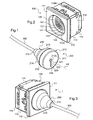
- FIG. 1 and 2 there is shown respectively an electrical plug 200 and a socket mechanism 100 into which the electrical plug 200 can be plugged.
- This plug-in mechanism 100 forms with this electrical plug 200 a connection assembly 1 (see FIG. figure 3 ) which is here more particularly intended for the hospital environment.
- the electrical plug 200 is located at the end of an electric cable 300 of a pear (not shown) of the type that patients use to call a nurse.
- the socket mechanism 100 is then mounted in an electrical box intended to be recessed in the wall of a hospital room, near the bed of a patient, and to be connected to the hospital electrical network. .
- the electrical plug 200 and the socket mechanism 100 each comprise connecting elements adapted to cooperate together.
- connection elements 220 of the electrical plug 200 are partly housed in an envelope 210 of insulating material, and are accessible through the front face 211 of the envelope 210.
- connection elements 120 of the socket mechanism 100 are also housed in an envelope 110 of insulating material, and are accessible through the front face 111 of the envelope 110.
- the casing 110 of the socket mechanism 100 fully houses, near its front face 111, a magnetic element 130, and the casing 210 of the electrical plug 200 fully houses , near its front face 211, a magnetizable element 230 non-magnetic.
- These magnetic and magnetizable elements 130, 230 are designed to hold the electrical plug 200 in position plugged into the socket mechanism 100, so as to close the electrical circuit between the call bulb and the hospital electrical network.
- a magnetic element 130 (rather than a mechanical detent element which may deteriorate) in the socket mechanism 100 ensures that the tensile force required to disengage the electrical plug 200 out of the socket mechanism 100 does not change over time.
- the socket mechanism 100 and the electrical plug 200 are preferably designed so that, in the plugged-in position, the magnetic element 130 induces on the magnetizable element 230 a pulling force of between 20 and 40 Newton.
- This attractive force is strong enough to keep the electrical plug 200 in the plugged position in the socket mechanism 100 as long as no significant pulling force is exerted on the plug.
- This attraction force is also low enough so that, in an emergency (typically on rising or lowering of the patient's bed), the electrical plug 200 can disconnect quickly without deteriorating or damaging the setting mechanism current 100.
- the socket mechanism 100 and the electrical plug 200 are preferably designed so that, in the plugged position, the magnetic and magnetizable elements 130, 230 are spaced apart by a distance, called the air gap, of between 1 and 3 millimeters. This gap is here equal to 2 millimeters.
- This gap is large enough to allow to design an envelope 210 electrical plug 200 sufficiently thick to be rigid and easily industrializable.
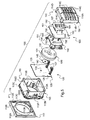
- the envelope 110 of the socket mechanism 100 is made in three parts, including a bottom 114, a sleeve 113 and a hubcap 112.
- the bottom 114 of the casing 110 has a flat and square rear wall 114A, bordered at the front by a peripheral rib 114B.
- the sleeve 113 is of square parallelepipedal shape, with four side walls 113B lined at the front, on the side of their inner faces, by a front edge 113A which delimits a wide circular opening 113G.
- the side walls 113B bear on their external faces, near the front edge 113A, a sidewalk 113C device which is here partially interrupted by indentations.
- the hubcap 112 comprises meanwhile a front plate 112A flat and square, bordered at the rear by a falling edge 112B.
- the front plate 112A recesses a well 112C crossing the home of the electrical plug 200, which is delimited by a cylindrical side wall.
- the falling edge 112B is adapted to be applied by its rear edge on the sidewalk 113C of the sleeve 113.
- the sleeve 113 For its mounting on the bottom 114 of the casing 110, the sleeve 113 comprises, on two opposite side walls 113B, four windows 113D.
- the bottom 114 carries in correspondence four latching lugs 114D which rise from its peripheral rib 114B, orthogonal to its rear wall 114A, and which bear claws adapted to catch on the windows 113D of the sleeve 113.
- the sleeve 113 comprises, at the front of the flange 113C, on two opposite side walls 113B, four grooves 113E in which claws 112E can be hooked up projecting from the inner face of the falling edge. 112B of the hubcap 112.
- the sleeve 113 For the mounting of the casing 110 of the socket mechanism 100 in the electrical box attached to the wall of the hospital chamber, the sleeve 113 comprises fixing means on an equipment support (not shown) which is itself adapted to be fixed on the electrical box.
- These fastening means comprise two latching tabs 113F which are cut in two opposite side walls 113B of the sleeve 113, at the rear of the flange 113C, and which bear claws adapted to hook onto the rear face of the support of FIG. apparatus when the sidewalk 113C of the sleeve 113 bears against the front face of this equipment support.
- the envelope 110 of the socket mechanism 100 When assembled, the envelope 110 of the socket mechanism 100 internally houses, from the front to the back, a printed circuit 125, an anti-short circuit element 140, the magnetic element 130, a support means 150 of the magnetic element 130, and a connection element 160 of the printed circuit 125. These different elements are superimposed and are held in position between the rear wall 114A of the bottom 114 and the front flange 113A of the sleeve 113.
- the printed circuit board 125 comprises a flat plane plate support 126 and copper tracks 121, 122, 123, 124 which extend on the two front and rear faces of the support 126.
- the support 126 has a thickness equal to 0.8 millimeters and a width, equal to the play, to the internal width of the sleeve 113. It is thus adapted to be pressed against the rear face of the front flange 113A of the sleeve 113. In this position, it closes the circular opening 113G delimited by the front flange 113A of the sleeve 113 and thus forms the bottom of the well 112C insertion of the electrical plug 200.
- the support 126 of the printed circuit 125 then has on the front face a white varnish, which is visible and which gives the whole a neat and clean appearance.
- the support 126 on its front face, carries four tracks 121, 122, 123, 124 extending in concentric circles in the center of the support.
- the diameter of the track of larger diameter is smaller than that of the circular opening 113G delimited by the front flange 113A of the sleeve 113. In this way, these four tracks 121, 122, 123, 124 are accessible at the bottom of the well 112C insertion of the electric plug 200.
- the central track and the outer track correspond to the phase and the neutral of the socket mechanism, while the intermediate tracks are used to circulate electrical signals to control the switching on and off of a light. call in the local nurses.
- the socket mechanism 100 is here supplied with "very low voltage backup", that is to say with a voltage of 24 volts (30 volts maximum) continuous and a maximum current of 250 milliamps.
- the support 126 carries other copper tracks. These tracks are connected with those of the front face of the support 126 by four via (term derived from the English “vertical interconnect access”, meaning in this case "through-through holes”). They are also connected with the connecting element 160 by two layers 127, which extend from the printed circuit 125 to this connection element 160.
- connection element 160 comprises a printed circuit, called the rear printed circuit 161, and a terminal block 162 which has four connection terminals (not visible in the figures). and which is attached to the rear of the rear printed circuit board 161.
- the rear printed circuit 161 comprises a support of dimensions identical to those of the support of the printed circuit 125, and copper tracks which extend on the rear face of this support.
- the terminal block 162 here comprises a base 167 made of insulating plastic material which internally houses the four connection terminals.
- This base 167 has a generally parallelepiped shape and is elongated along an axis parallel to the plane of the support of the rear printed circuit 161 to accommodate the four connection terminals in side-by-side position.
- This base 167 has on the rear face four first parallel holes 164 to access the four connection terminals, which allow to engage the stripped ends of four son of the hospital electrical network in the four connection terminals.
- Four rectangular windows 114C are provided in correspondence in the rear wall 114A of the bottom 114 of the casing 110, to allow access to the first four parallel holes 164.
- the base 167 of the terminal block 162 also has on the side face four second parallel holes 163 for accessing tapped bores equipping the four connection terminals. These tapped bores accommodate four fastening screws (not shown) to block the stripped ends of the four son in the four connection terminals to connect them. As shown in figure 2 , the envelope 110 then has an access opening 110H to these four parallel second holes 163, to allow the tip of a screwdriver to access the heads of these fixing screws.
- this access opening 110H is defined between two notches 113H, 114H, one of which is recessed in the rear edge of one of the side walls 113B of the sleeve 113 of the envelope 110 and the other of which is provided hollow in the front edge of the peripheral rib 114B of the bottom 114 of the casing 110.
- the base 167 of the terminal block 162 has on the front face four third parallel holes (not visible in the figures), which allow four metal pins 165 fitted to the four connection terminals to project at the front of the base 167.
- These four pins metal 165 are engaged in four vias provided in correspondence in the support of the rear printed circuit 161. They then allow not only to fix the terminal block 162 to the rear printed circuit 161, but also to connect the four connection terminals to the tracks of this rear printed circuit 161.
- connection terminals are thus connected to the four tracks 121, 122, 123, 124 provided on the front face of the support of the printed circuit 125.
- the anti-short circuit element 140 comprises a disc-shaped base 142, and a pin 141 which protrudes from the center of the front face of the base 142.
- the base 142 has a diameter much smaller than the width of the printed circuit 125. It is thus adapted to be applied against the rear face of the support 126 of the printed circuit 125 so that the pin 141 engages through an opening 128 provided in correspondence with the center of the support 126 of the printed circuit 125.
- the pin 141 has for this purpose a diameter smaller than that of the track 121 of smaller diameter and equal, with the game, to that of the opening 128. It also has a height strictly greater than the thickness of the support 126 of the printed circuit 125.
- the anti-short circuit element 140 is made in one piece of insulating plastic material.
- the pin 141 will prevent this object from being applied to this printed circuit 125 and to enter simultaneously in contact with several tracks 121, 122, 123, 124 of the printed circuit 125.
- the anti-short circuit element 140 can thus avoid the occurrence of a short circuit.
- the magnetic element 130 is placed between the connection element 160 and the anti-short circuit element 140.
- the magnet 131 has a cylindrical shape of revolution about an axis A1 orthogonal to the plane of the support 126 of the printed circuit 125. It has a diameter of 32 millimeters and a height of 7 millimeters. It is thus accommodable in a casing 110 of socket mechanism 100 of conventional size. It presents here a central through hole 133 of axis A1, of diameter slightly lower than that of the base 142 of the anti-short circuit element 140.
- the magnet 131 is here of neodymium type.
- the magnetizable element 230 of the electrical plug 200 is automatically centered in the axis A1 of the magnet 131 when brought close to it.
- the metal cage 132 has a shape and dimensions homologous to those of the magnet 131. It is attached to the magnet 131 in the extension thereof, and thus makes it possible to orient the magnetic flux coming from the magnet 131. 131 magnet in a single half-sphere facing forward, so as to optimize the attractive force generated by the magnet 131 and to protect the back of the socket 100 of the magnetic field from the magnet 131.
- the support means 150 of the magnetic element 130 is arranged to hold the latter in a fixed position in the envelope 110.
- FIG. 5 it comprises for this purpose a cradle 151 for receiving the magnetic element 130, and fixing means 152, 157 of this cradle 151 on the printed circuits 125, 161.
- the cradle 151 has a flat bottom 153 of generally rectangular shape, with two opposite edges rectilinear and parallel, and two other rounded opposite edges, circumscribed to the same circle of diameter equal to that of the magnetic element 130. It also comprises two flanges 154 which rise vis-à-vis from these two rounded edges, on a height approximately equal to that of the magnetic element 130, to delimit between them a housing for receiving this magnetic element 130.
- each rim 156 has a lug 157 which projects from its projection. front face to engage in a hole 129 provided in correspondence in the support 127 of the printed circuit 125. These pins 157 and allow to properly center the magnetic element 130 in the axis of the support 127 of the printed circuit 125.
- the cradle 151 also rests on the support of the rear printed circuit 161 by two rectilinear and parallel ribs 155 which project from the rear face of its flat bottom 153.
- latching means here comprising two latching lugs 152.
- latching means here comprising two latching lugs 152.
- these two latching tabs 152 extend in length from the rear face of the flat bottom 153 of the cradle 151, orthogonally thereto, and carry at their free ends two claws facing away from each other. the other.
- the support of the rear printed circuit 161 comprises in correspondence two circular openings 166 through which the detent tabs 152 can engage so that their claws cling to the rear face of this support.
- the electrical plug 200 is for its part represented on the figures 1 and 6 .
- Its envelope 210 generally has a right conical shape of A2 axis of revolution, whose vertex is truncated.
- It is made of three distinct parts, each resulting from molding of an insulating plastic material. It more particularly comprises a front cover 212, which forms the base of the cone, and a rear body 216 consisting of two parts 213, 214 identical, which forms the side wall of the cone.
- the front cover 212 has a front wall 212A disk-shaped axis of revolution A2, which is bordered on the rear side by a falling edge 212B cylindrical about the axis of revolution A2.
- the front wall 212A has a small thickness, here equal to 1.2 millimeters, arranged so that the air gap provided between the magnetic elements 130 and magnetizable 230 has a reduced value.
- This front wall 212A has a central orifice 212C of equal diameter, clearance, to that of the pin 141 of the anti-short circuit element 140 of the socket mechanism 100.
- the electrical plug 200 can be attached to the bottom of the well 112C of the socket mechanism 100, so that the front face 211 of its casing 210 is uniformly applied against the front face of the circuit board 125 of the socket mechanism 100.
- the falling edge 212B of the front cover 212 for its part, has an outside diameter equal, with play, to the diameter of the well 112C of the socket mechanism 100.
- the electrical plug 200 is adapted to be centered automatically, by form cooperation, in well 112C.
- the two parts 213, 214 of the rear body 216 of the casing 210 allow to connect continuously and aesthetically the front cover 212 to the side face of the electric cable 300.
- the truncated apex of the cone has for this purpose a square opening 215 for the passage of the electric cable 300.
- the latter is equipped, near its free end, with a generally conical seal 310 which, as shown in FIG. figure 1 , is designed to aesthetically extend the conical shape of the envelope 210.
- this joint 310 has at mid-height a narrowing section 315 of square shape, on which can close the square opening 215 of the casing 210.
- the base of the cone formed by the two parts 213, 214 of the rear body 216 of the casing 210 is further closed by a partition 214B, 214C which defines an oblong central opening 217.
- the two parts 213, 214 of the rear body 216 of the casing 210 are adapted to fit one on the other and to lock in this position by means of latching means 218, 219.
- latching means comprise for this purpose two tabs 218, 219 which rise in parallel, projecting from the inner face of each portion 213, 214 of the rear body 216 of the casing 210. They comprise more precisely, on each part 213, 214 of the rear body 216, a first leg 219 which has on the side of its free end an opening 219A and a second leg 219 which has on the side of its free end a claw 218A adapted to engage in the opening 219A provided on the first leg 219 of the other portion 213, 214 of the rear body 216 of the casing 210.
- the front cover 212 is adapted to fit on the rear body 216 of the casing 210. Its falling edge 212B has for this purpose, recessed in its inner face, a peripheral groove (not visible in the figures) in which can engage a peripheral rib 213A, 214A provided in correspondence on the rear body 216 of the casing 210, projecting from the rear face of the partition 214B, 214C.
- connection means 220 provided in the envelope 210 here comprise a support plate 225 of rectangular shape.
- This support plate 225 carries on its rear face a connection terminal block 226 in which can be connected a connecting element 320 provided corresponding to the end of the electric cable 300.
- These four openings 212D are placed on four circles which are concentric in the center of the front wall 212A of the front cover 212 and which have diameters equal to the diameters of the tracks 121, 122, 123, 124 provided on the front face of the printed circuit 125 of the outlet mechanism 100.
- the four connectors 221, 222, 223, 224 are piston connectors. They therefore each comprise a conductive rod which slides in a sleeve between a retracted position and an extended position, and which is automatically recalled in the extended position to ensure good electrical contact between the connectors 221, 222, 223, 224 and the tracks. 121, 122, 123, 124.
- the four connectors 221, 222, 223, 224 are here arranged side by side. It is then provided, projecting from the rear face of the front wall 212A of the front cover 212 of the casing 210, a rib (not visible in the figures) which extends in a rectangular contour around the openings 212D and which forms a housing housing the sleeves of these connectors 221, 222, 223, 224.
- This rib thus makes it possible to maintain the support plate 225 at the rear of the front wall 212A of the front cover 212, in the axis of the openings 212D.
- the support plate 225 is also locked in this position between the wall 213B, 214B of the rear body 216 of the casing 210 and the magnetizable element 230.
- this magnetizable element 230 has a washer shape, with a substantially cylindrical slice of revolution about the axis A2. It has here a diameter identical to that of the magnetic element 130 of the socket mechanism 100 and a thickness greater than 1 millimeter, here equal to 1.5 millimeters. Thanks to this shape, the magnetic field induced by the magnetic element 130 perfectly buckles on this magnetizable element 230, so that it exerts an optimum force of attraction thereon.
- the magnetizable element 230 is made of a single piece of metal material. It is more precisely made of mild steel with a carbon content of less than 1%.
- This rectangular central opening 231 is extended at one of its ends by a portion 233 through which the four connectors 221, 222, 223, 224 pass.
- This portion 233 has dimensions such that the magnetizable element 230 is adapted to engage on the rectangular rib projecting from the rear face of the front wall 212A of the front cover 212 of the casing 210.
- the magnetizable element 230 also has two circular orifices 232, located on either side of the central rectangular opening 231, the function of which will be specified later in this description.
- this magnetizable element 230 is adapted to be locked against the rear face of the front wall 212A of the front cover 212, by latching claws (not visible in the figures) provided projecting from the inner face of the falling edge 212B of the front cover 212.
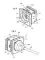
- connection assembly 1 there is shown a second embodiment of the connection assembly 1 according to the invention.
- connection assembly 1 comprises a plug 200 and a power outlet mechanism 100 of forms similar to those of the electrical plug and the socket mechanism of the first embodiment.
- connection assembly of the first embodiment comprises parts that are strictly identical to those of the connection assembly of the first embodiment, so as to avoid doubling the references of these parts when it is desired to manufacture the two embodiments of the connection assembly. .
- the electrical plug 200 and socket 100 of this second embodiment of the connection assembly 1 are distinguished mainly from the electrical plug and outlet of the first embodiment by their connecting elements 120 ', 220 '.
- connection elements 120 ', 220' which are accessible on the front faces 111, 211 of the envelopes 110, 210 of the electrical plug 200 and socket 100 are indeed not arranged on circles.
- These polarizing means here comprise, on the electrical plug 200, a lug 270 'which protrudes from the outer face of the falling edge 212B' of the front cover 212 'of the casing 210.
- a housing 170 ' which extends hollow in the cylindrical wall delimiting the well 112C' of the hubcap 112 'of the casing 110.
- the socket mechanism 100 of this second embodiment of the connection assembly 1 is more particularly represented on the figures 8 and 10 .
- the magnetic element 130 and the support means 150 of this socket 100 have shapes identical to those of the magnetic element and the support means of the first embodiment.
- the printed circuit 125 has a different shape.
- connection zones 121 'of copper of oblong shapes and reduced in size, distributed in two parallel rows, in the center of the support so as to be accessible at the bottom of the well 112C' of the outlet mechanism 100.
- connection zones 121 'by vias and, on the other, to pins 127' adapted to to connect in electrical terminals 167 'provided in correspondence on the connecting element 160'.
- connection element 160 ' for its part comprises a printed circuit 161' and two terminal blocks 162 'arranged back to back on the back of this printed circuit 161'.
- terminal blocks 162 ' each comprise six connection terminals (not visible in the figures) connected to the electrical terminals 167' by copper tracks provided on the rear face of the support of the printed circuit 161 '.
- the rear wall 114A 'of the bottom 114' of the casing 110 of the socket mechanism 100 then comprises twelve rectangular windows 114C 'for engaging the stripped ends of twelve electrical wires in these twelve connection terminals.
- the sleeve 113 'and the bottom 114' of the envelope 110 also define at their junction two access openings 110H 'allowing the tip of a screwdriver to access the heads of the fastening screws fitted to these twelve connection terminals .
- the support of the printed circuit 125 'then has two openings 128' for passing pins 141 of these two anti-short circuit elements 140, which are located on either side of the two rows of connection areas 121 '.
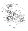
- the electrical plug 200 of this second embodiment of the connection assembly 1 is more particularly represented on the figures 7 and 11 .
- the magnetizable element 230 and the rear body 216 of the envelope 210 have identical shapes to those of the magnetizable element and the rear body of the first embodiment.
- connection means 220 'of this electrical plug 200 have different shapes.
- connection means 220 here in fact comprise a support plate 225' of rectangular shape equipped on its rear face with a connection terminal block 226 'and on its front face two rows of six piston connectors 221'.
- connection terminal block 226 ' which is arranged to receive the connecting element 320' provided corresponding to the end of the electric cable 300, here comprises twelve electrical terminals connected to the twelve piston connectors 221 '.
- These twelve piston connectors 221 ' are arranged to project from the front face 211 of the front cover 212' of the casing 210, through twelve openings 212D 'provided correspondingly in the front wall 212A' of this hood before 212 '.
- a rectangular rib (not visible in the figures) which extends around the openings 212D 'to form a housing housing the piston connectors 221 '.
- this rectangular rib has dimensions identical to those of the rectangular central opening 231 of the magnetizable element 230.
- This magnetizable element 230 is thus adapted to engage on this rectangular rib, in order to be applied against the rear face of the front wall 212A 'of the front cover 212' of the casing 210.
- the front wall 212A 'of the front cover 212' has two lateral orifices 212C ', located on either side of the openings 212D', of equal diameter, with the clearance, to the diameter of the pins 141 of the elements. short circuit 140 of the socket mechanism 100.
- These two lateral orifices 212C ' are thus arranged not to prevent the passage of the pins 141 of the anti-short circuit elements 140 when connecting the electrical plug 200 in the mechanism socket outlet 100.
- the two aforementioned circular orifices 232 of the magnetizable element 230 are then provided to extend in the extension of the lateral orifices 212C ' of the front cover 212 ', so as not to hinder the passage of the pins 141 of the anti-short circuit elements 140.
Description
La présente invention concerne de manière générale le domaine des connecteurs électriques.The present invention generally relates to the field of electrical connectors.
Elle concerne plus particulièrement un ensemble de connexion électrique tel que défini dans le préambule de la revendication 1.It relates more particularly to an electrical connection assembly as defined in the preamble of claim 1.
On connaît notamment du document
Dans ce document, les éléments de connexion de la prise de courant comportent, en saillie de la face de connexion de l'enveloppe de la prise, trois anneaux concentriques.In this document, the connection elements of the socket comprise, projecting from the connection face of the jack envelope, three concentric rings.
Les éléments de connexion de la fiche électrique comporte quant à eux, en saillie de la face de connexion de l'enveloppe de la fiche, un plot central et deux plots latéraux placés sur des cercles concentriques de mêmes diamètres que les anneaux concentriques de la prise de courant.The connecting elements of the electrical plug comprises, in turn, projecting from the connecting face of the plug casing, a central stud and two lateral studs placed on concentric circles of the same diameter as the concentric rings of the plug. current.
Grâce à ces éléments de connexion, lorsque la fiche électrique est enfichée dans la prise de courant, les plots de la fiche électrique se connectent aux anneaux de la prise de courant, de manière à fermer le circuit électrique entre la fiche électrique et la prise de courant.Thanks to these connection elements, when the plug is plugged into the socket, the plugs of the plug connect to the rings of the socket, so as to close the electrical circuit between the plug and the plug of the plug. current.
Dans ce document, les enveloppes de la fiche électrique et de la prise de courant logent chacune un aimant en forme d'anneau.In this document, the envelopes of the plug and socket each house a magnet shaped ring.
Ces aimants permettent ainsi de maintenir la fiche électrique enfichée dans la prise de courant tant qu'aucun effort de traction n'est exercé sur elle.These magnets thus make it possible to keep the electrical plug plugged into the socket as long as no traction force is exerted on it.
L'inconvénient majeur de cet ensemble de connexion est que la fiche électrique comme la prise de courant comportent un aimant susceptible d'interférer avec les circuits électroniques des appareils médicaux sensibles aux champs magnétiques (par exemple les stimulateurs cardiaques). Il ne peut donc pas être utilisé en milieu hospitalier.The major disadvantage of this connection assembly is that the electrical plug as the socket has a magnet that may interfere with the electronic circuits of medical devices sensitive to magnetic fields (eg pacemakers). It can not be used in hospitals.
On connaît par ailleurs du document
La fabrication de tels moyens de connexion s'avère alors difficile à mettre en oeuvre et onéreuse. Le résultat présente par ailleurs une robustesse limitée.The manufacture of such connection means is then difficult to implement and expensive. The result also has a limited robustness.
Afin de remédier aux inconvénients précités de l'état de la technique, la présente invention propose un nouvel ensemble de connexion, dans lequel la fiche électrique est dépourvue d'aimant et dans lequel les moyens de connexion sont simples et robustes.In order to overcome the aforementioned drawbacks of the state of the art, the present invention proposes a new connection assembly, in which the electrical plug is devoid of a magnet and in which the connection means are simple and robust.
Plus particulièrement, on propose selon l'invention un ensemble de connexion électrique tel que défini dans la revendication 1.More particularly, there is provided according to the invention an electrical connection assembly as defined in claim 1.
La fiche électrique, lorsqu'elle est débranchée, est susceptible d'être déplacée jusqu'à proximité d'un appareil sensible aux champs magnétiques. Grâce à l'invention, elle ne génère alors aucune interférence, si bien que son utilisation ne présente aucun danger.The plug, when disconnected, can be moved to near a magnetic field sensitive device. Thanks to the invention, it does not generate any interference, so that its use is safe.
L'utilisation d'un élément magnétique dans la prise de courant s'avère par ailleurs sans danger puisque, cette prise étant fixée au mur, il est improbable qu'un appareil sensible aux champs magnétiques se retrouve à proximité immédiate de la prise de courant.The use of a magnetic element in the socket is also safe because, since this socket is fixed to the wall, it is unlikely that a device sensitive to magnetic fields is found in the immediate vicinity of the socket .
Enfin, dans l'invention, la stérilité de l'ensemble de connexion est assurée par la position des éléments magnétique et magnétisable (entièrement logés à l'intérieur des enveloppes de la prise de courant et de la fiche électrique), remplissant ainsi une condition sine qua non pour son utilisation en milieu hospitalier.Finally, in the invention, the sterility of the connection assembly is ensured by the position of the magnetic and magnetizable elements (fully housed inside the casings of the socket and the electrical plug), thus fulfilling a condition sine qua non for its use in hospitals.
D'autres caractéristiques avantageuses et non limitatives de l'ensemble de connexion conforme à l'invention sont définies dans les revendications 2 et suivantes.Other advantageous and non-limiting characteristics of the connection assembly according to the invention are defined in claims 2 and following.
La description qui va suivre, en regard des dessins annexés, donnée à titre d'exemple non limitatif, fera bien comprendre en quoi consiste l'invention et comment elle peut être réalisée.The description which follows, with reference to the accompanying drawings, given by way of non-limiting example, will make it clear what the invention consists of and how it can be achieved.
Sur les dessins annexés :
- les
figures 1 et 2 sont des vues schématiques en perspective d'une fiche électrique et d'un mécanisme de prise de courant d'un ensemble de connexion selon un premier mode de réalisation de l'invention ; - la
figure 3 est une vue schématique en perspective de cet ensemble de connexion, sur laquelle la fiche électrique de lafigure 1 est représentée en position enfichée dans le mécanisme de prise de courant de lafigure 2 ; - les
figures 4 et5 sont des vues schématiques en perspective éclatée du mécanisme de prise de courant de lafigure 2 , représenté sous deux angles différents ; - la
figure 6 est une vue schématique en perspective éclatée de la fiche électrique de lafigure 1 ; - les
figures 7 et8 sont des vues schématiques en perspective d'une fiche électrique et d'un mécanisme de prise de courant d'un ensemble de connexion selon un second mode de réalisation de l'invention ; - la
figure 9 est une vue schématique en perspective de l'ensemble de connexion desfigures 7 et8 , sur laquelle la fiche électrique est représentée en position enfichée dans le mécanisme de prise de courant ; - la
figure 10 est une vue schématique en perspective éclatée du mécanisme de prise de courant de lafigure 8 ; et - la
figure 11 est une vue schématique en perspective éclatée de la fiche électrique de lafigure 7 .
- the
Figures 1 and 2 are schematic perspective views of an electrical plug and a socket mechanism of a connection assembly according to a first embodiment of the invention; - the
figure 3 is a schematic perspective view of this connection assembly, on which the electrical plug of thefigure 1 is shown in position plugged into the socket mechanism of thefigure 2 ; - the
figures 4 and5 are schematic views in exploded perspective of the socket mechanism of thefigure 2 , represented from two different angles; - the
figure 6 is a schematic exploded perspective view of the electrical plug of thefigure 1 ; - the
figures 7 and8 are schematic perspective views of an electrical plug and a socket mechanism of a connection assembly according to a second embodiment of the invention; - the
figure 9 is a schematic perspective view of the connection set offigures 7 and8 , on which the electric plug is shown in the inserted position in the socket mechanism; - the
figure 10 is a schematic exploded perspective view of the socket mechanism of thefigure 8 ; and - the
figure 11 is a schematic exploded perspective view of the electrical plug of thefigure 7 .
En préliminaire, on notera que les éléments identiques ou similaires des différents modes de réalisation de l'invention représentés sur les différentes figures seront, dans la mesure du possible, référencés par les mêmes signes de référence et ne seront pas décrits à chaque fois.In preliminary, it will be noted that the identical or similar elements of the different embodiments of the invention shown in the different figures will, as far as possible, be referenced by the same reference signs and will not be described each time.
Dans la suite de la description, les termes « avant » et « arrière » seront utilisés par rapport aux faces de contact des deux éléments de l'ensemble de connexion électrique selon l'invention. Plus précisément, la face de chaque élément qui sera adaptée à venir en contact contre l'autre élément sera appelée face avant, tandis que la face opposée sera appelée face arrière.In the remainder of the description, the terms "front" and "back" will be used with respect to the contact faces of the two elements of the electrical connection assembly according to the invention. More precisely, the face of each element which will be adapted to come into contact with the other element will be called the front face, while the opposite face will be called the back face.
Sur les
Ce mécanisme de prise de courant 100 forme avec cette fiche électrique 200 un ensemble de connexion 1 (voir
Ici, avantageusement, la fiche électrique 200 est située à l'extrémité d'un câble électrique 300 d'une poire d'appel (non représentée) du type de celles que les patients utilisent pour appeler une infirmière.Here, advantageously, the
Le mécanisme de prise de courant 100 est alors ici monté dans une boîte électrique destinée à être encastrée dans le mur d'une chambre d'hôpital, à proximité du lit d'un patient, et à être connecté au réseau électrique de l'hôpital.The
Pour connecter la poire d'appel à ce réseau électrique, la fiche électrique 200 et le mécanisme de prise de courant 100 comportent chacun des éléments de connexion adaptés à coopérer ensemble.To connect the call bulb to this electrical network, the
Comme le montre la
Comme le montre la
Comme le montrent les
Ces éléments magnétique et magnétisable 130, 230 sont conçus pour retenir la fiche électrique 200 en position enfichée dans le mécanisme de prise de courant 100, de manière à fermer le circuit électrique entre la poire d'appel et le réseau électrique de l'hôpital.These magnetic and
L'utilisation d'un élément magnétique 130 (plutôt que d'un élément mécanique d'encliquetage susceptible de se détériorer) dans le mécanisme de prise de courant 100 permet d'assurer que l'effort de traction nécessaire pour dégager la fiche électrique 200 hors du mécanisme de prise de courant 100 ne varie pas au cours du temps.The use of a magnetic element 130 (rather than a mechanical detent element which may deteriorate) in the
La position de ces éléments magnétique et magnétisable 130, 230 (entièrement logés à l'intérieur des enveloppes 110, 210) permet par ailleurs de faciliter leur nettoyage, au bénéfice de la stérilité de l'ensemble de connexion 1.The position of these magnetic and
Le mécanisme de prise de courant 100 et la fiche électrique 200 sont préférentiellement conçus de manière que, en position enfichée, l'élément magnétique 130 induit sur l'élément magnétisable 230 une force d'attraction comprise entre 20 et 40 Newton.The
Cette force d'attraction est suffisamment forte pour permettre de conserver la fiche électrique 200 en position enfichée dans le mécanisme de prise de courant 100 tant qu'aucun effort de traction important n'est exercé sur cette fiche.This attractive force is strong enough to keep the
Cette force d'attraction est par ailleurs suffisamment faible pour que, en cas d'urgence (typiquement à la montée ou à la descente du lit du patient), la fiche électrique 200 puisse se déconnecter rapidement sans se détériorer ni détériorer le mécanisme de prise de courant 100.This attraction force is also low enough so that, in an emergency (typically on rising or lowering of the patient's bed), the
Le mécanisme de prise de courant 100 et la fiche électrique 200 sont préférentiellement conçus de manière que, en position enfichée, les éléments magnétique et magnétisable 130, 230 sont écartés d'une distance, appelée entrefer, comprise entre 1 et 3 millimètres. Cet entrefer est ici égal à 2 millimètres.The
Cet entrefer est suffisamment important pour permettre de concevoir une enveloppe 210 de fiche électrique 200 suffisamment épaisse pour être rigide et facilement industrialisable.This gap is large enough to allow to design an
Il est par ailleurs suffisamment faible pour permettre à l'élément magnétique 130 d'induire sur l'élément magnétisable 230 une force d'attraction optimale sans pour autant présenter des dimensions trop importantes.It is also low enough to allow the
Telle que représentée sur les
Le fond 114 de l'enveloppe 110 présente une paroi arrière 114A plane et carrée, bordée à l'avant par une nervure périphérique 114B.The
Le manchon 113 est de forme parallélépipédique carrée, avec quatre parois latérales 113B bordées à l'avant, du côté de leurs faces intérieures, par un rebord avant 113A qui délimite une large ouverture circulaire 113G. Les parois latérales 113B portent sur leurs faces externes, à proximité du rebord avant 113A, un trottoir 113C périphérique qui est ici partiellement interrompu par des échancrures.The
L'enjoliveur 112 comporte quant à lui une plaque frontale 112A plane et carrée, bordée à l'arrière par un bord tombant 112B. La plaque frontale 112A présente en renfoncement un puits 112C traversant d'accueil de la fiche électrique 200, qui est délimité par une paroi latérale de forme cylindrique. Le bord tombant 112B est adapté à s'appliquer par sa tranche arrière sur le trottoir 113C du manchon 113.The
Pour son montage sur le fond 114 de l'enveloppe 110, le manchon 113 comporte, sur deux parois latérales 113B opposées, quatre fenêtres 113D. Le fond 114 porte en correspondance quatre pattes d'encliquetage 114D qui s'élèvent à partir de sa nervure périphérique 114B, orthogonalement à sa paroi arrière 114A, et qui portent des griffes adaptées à s'accrocher aux fenêtres 113D du manchon 113.For its mounting on the
Pour la fixation de l'enjoliveur 112, le manchon 113 comporte à l'avant du rebord 113C, sur deux parois latérales 113B opposées, quatre rainures 113E dans lesquelles peuvent s'accrocher des griffes 112E prévues en saillie de la face intérieure du bord tombant 112B de l'enjoliveur 112.For fixing the
Pour le montage de l'enveloppe 110 du mécanisme de prise de courant 100 dans la boîte électrique rapportée sur le mur de la chambre d'hôpital, le manchon 113 comporte des moyens de fixation sur un support d'appareillage (non représenté) qui est lui-même adapté à être fixé sur la boîte électrique. Ces moyens de fixation comprennent deux pattes d'encliquetage 113F qui sont découpées dans deux parois latérales 113B opposées du manchon 113, à l'arrière du rebord 113C, et qui portent des griffes adaptées à s'accrocher à la face arrière du support d'appareillage lorsque le trottoir 113C du manchon 113 est en appui contre la face avant de ce support d'appareillage.For the mounting of the
Lorsqu'elle est assemblée, l'enveloppe 110 du mécanisme de prise de courant 100 loge intérieurement, depuis l'avant vers l'arrière, un circuit imprimé 125, un élément anti-court-circuit 140, l'élément magnétique 130, un moyen de support 150 de l'élément magnétique 130, et un élément de connexion 160 du circuit imprimé 125. Ces différents éléments sont superposés et sont maintenus en position entre la paroi arrière 114A du fond 114 et le rebord avant 113A du manchon 113.When assembled, the
Tel que représenté sur les
Le support 126 présente une épaisseur égale à 0,8 millimètre et une largeur égale, au jeu près, à la largeur intérieure du manchon 113. Il est ainsi adapté à se plaquer contre la face arrière du rebord avant 113A du manchon 113. Dans cette position, il ferme l'ouverture circulaire 113G délimitée par le rebord avant 113A du manchon 113 et forme ainsi le fond du puits 112C d'insertion de la fiche électrique 200.The
Le support 126 du circuit imprimé 125 présente alors en face avant un vernis blanc, qui est visible et qui confère à l'ensemble un aspect propre et net.The
Comme le montre la
Ici, la piste centrale et la piste extérieure correspondent à la phase et au neutre du mécanisme de prise de courant, tandis que les pistes intermédiaires permettent de faire circuler des signaux électriques pour commander l'allumage et l'extinction d'une lumière d'appel dans le local d'infirmières. Le mécanisme de prise de courant 100 est ici alimenté en « très basse tension secourue », c'est-à-dire avec une tension de 24 Volts (30 Volts maximum) continue et un courant maximum de 250 milliAmpères.Here, the central track and the outer track correspond to the phase and the neutral of the socket mechanism, while the intermediate tracks are used to circulate electrical signals to control the switching on and off of a light. call in the local nurses. The
Bien que cela n'apparaisse pas sur la
Comme le montrent les
Le circuit imprimé arrière 161 comprend un support de dimensions identiques à celles du support du circuit imprimé 125, et des pistes en cuivre qui s'étendent sur la face arrière de ce support.The rear printed
Le bornier 162 comporte ici un socle 167 en matière plastique isolante, qui loge intérieurement les quatre bornes de connexion. Ce socle 167 présente une forme globalement parallélépipédique et est allongé selon un axe parallèle au plan du support du circuit imprimé arrière 161 afin de loger les quatre bornes de connexion en position côte à côte.The
Ce socle 167 présente en face arrière quatre premiers trous parallèles 164 d'accès aux quatre bornes de connexion, qui permettent d'engager les extrémités dénudées de quatre fils du réseau électrique de l'hôpital dans les quatre bornes de connexion. Quatre fenêtres rectangulaires 114C sont prévues en correspondance dans la paroi arrière 114A du fond 114 de l'enveloppe 110, pour permettre d'accéder aux quatre premiers trous parallèles 164.This
Le socle 167 du bornier 162 présente par ailleurs en face latérale quatre seconds trous parallèles 163 d'accès à des alésages taraudés équipant les quatre bornes de connexion. Ces alésages taraudés permettent d'accueillir quatre vis de fixation (non représentées) afin de bloquer les extrémités dénudées des quatre fils dans les quatre bornes de connexion pour les y connecter. Comme le montre la
Tel que représenté sur les
Ces pistes étant par ailleurs connectées aux nappes 127, les quatre bornes de connexion sont ainsi connectées aux quatre pistes 121, 122, 123, 124 prévues sur la face avant du support du circuit imprimé 125.These tracks being moreover connected to the
Comme le montre la
L'embase 142 présente un diamètre très inférieur à la largeur du circuit imprimé 125. Elle est ainsi adaptée à s'appliquer contre la face arrière du support 126 du circuit imprimé 125 de telle sorte que le pion 141 s'engage au travers d'une ouverture 128 prévue en correspondance au centre du support 126 du circuit imprimé 125.The
Le pion 141 présente à cet effet un diamètre inférieur à celui de la piste 121 de plus petit diamètre et égal, au jeu près, à celui de l'ouverture 128. Il présente par ailleurs une hauteur strictement supérieure à l'épaisseur du support 126 du circuit imprimé 125.The
L'élément anti-court-circuit 140 est réalisé d'une seule pièce en matière plastique isolante.The
Ainsi, si un objet métallique quelconque (telle qu'une pièce de monnaie) est attiré par l'élément magnétique 130 contre le circuit imprimé 125, le pion 141 empêchera cet objet de s'appliquer sur ce circuit imprimé 125 et d'entrer simultanément en contact avec plusieurs pistes 121, 122, 123, 124 du circuit imprimé 125. En empêchant cet objet métallique de réaliser un contact électrique entre les pistes 121, 124 de phase et de neutre, l'élément anti-court-circuit 140 peut ainsi éviter l'apparition d'un court-circuit.Thus, if any metal object (such as a coin) is attracted by the
Comme le montrent les
Il comporte ici un aimant 131 permanent et une cage métallique 132 qui est fixée à l'arrière de cet aimant 131.It comprises here a
L'aimant 131 présente une forme cylindrique de révolution autour d'un axe A1 orthogonal au plan du support 126 du circuit imprimé 125. Il présente un diamètre de 32 millimètres et une hauteur de 7 millimètres. Il est ainsi logeable dans une enveloppe 110 de mécanisme de prise de courant 100 de taille classique. Il présente ici un trou central traversant 133 d'axe A1, de diamètre légèrement inférieur à celui de l'embase 142 de l'élément anti-court-circuit 140.The
L'aimant 131 est ici de type néodyme.The
Comme cela est représenté en traits discontinus sur la
Grâce à cette configuration, l'élément magnétisable 230 de la fiche électrique 200 se centre automatiquement dans l'axe A1 de l'aimant 131 lorsqu'il est amené à proximité de celui-ci.With this configuration, the
La cage métallique 132 présente pour sa part une forme et des dimensions homologues à celles de l'aimant 131. Elle est fixée à l'aimant 131 dans le prolongement de celui-ci, et permet ainsi d'orienter le flux magnétique issu de l'aimant 131 dans une seule demi-sphère orientée vers l'avant, de manière à optimiser la force d'attraction générée par l'aimant 131 et à protéger l'arrière de la prise de courant 100 du champs magnétique issu de l'aimant 131.The
Le moyen de support 150 de l'élément magnétique 130 est agencé pour maintenir ce dernier en position fixe dans l'enveloppe 110.The support means 150 of the
Comme le montre la
Le berceau 151 présente un fond plat 153 de forme globalement rectangulaire, avec deux bords opposés rectilignes et parallèles, et deux autres bords opposés arrondis, circonscrits à un même cercle de diamètre égal à celui de l'élément magnétique 130. Il comporte également deux flasques 154 qui s'élèvent en vis-à-vis à partir de ces deux bords arrondis, sur une hauteur environ égale à celle de l'élément magnétique 130, pour délimiter entre eux un logement d'accueil de cet élément magnétique 130.The
Comme le montre la
Comme le montre la
Il est rigidement fixé sur le circuit imprimé arrière 161 par des moyens d'encliquetage, comportant ici deux pattes d'encliquetage 152. Comme le montre la
La fiche électrique 200 est pour sa part représentée sur les
Son enveloppe 210 présente globalement une forme de cône droit d'axe de révolution A2, dont le sommet est tronqué.Its
Elle est réalisée en trois parties distinctes, chacune issue de moulage d'une matière plastique isolante. Elle comporte plus particulièrement un capot avant 212, qui forme la base du cône, et un corps arrière 216 constitué de deux parties 213, 214 identiques, qui forme la paroi latérale du cône.It is made of three distinct parts, each resulting from molding of an insulating plastic material. It more particularly comprises a
Le capot avant 212 présente une paroi frontale 212A en forme de disque d'axe de révolution A2, qui est bordée du côté arrière par un bord tombant 212B cylindrique autour de l'axe de révolution A2.The
La paroi frontale 212A présente une faible épaisseur, ici égale à 1,2 millimètre, agencée pour que l'entrefer prévu entre les éléments magnétique 130 et magnétisable 230 ait une valeur réduite.The
Cette paroi frontale 212A comporte un orifice central 212C de diamètre égal, au jeu près, à celui du pion 141 de l'élément anti-court-circuit 140 du mécanisme de prise de courant 100. De cette manière, la fiche électrique 200 peut être rapportée au fond du puits 112C du mécanisme de prise de courant 100, de telle manière que la face avant 211 de son enveloppe 210 s'applique uniformément contre la face avant du circuit imprimé 125 du mécanisme de prise de courant 100.This
Le bord tombant 212B du capot avant 212 présente pour sa part un diamètre extérieur égal, au jeu près, au diamètre du puits 112C du mécanisme de prise de courant 100. De cette manière, la fiche électrique 200 est adaptée à se centrer automatiquement, par coopération de forme, dans le puits 112C.The falling
Les deux parties 213, 214 du corps arrière 216 de l'enveloppe 210 permettent de raccorder continûment et esthétiquement le capot avant 212 à la face latérale du câble électrique 300.The two
Le sommet tronqué du cône présente à cet effet une ouverture carrée 215 de passage du câble électrique 300.The truncated apex of the cone has for this purpose a
Afin d'assurer l'étanchéité entre l'ouverture carrée 215 de l'enveloppe 210 et le câble électrique 300, ce dernier est équipé, à proximité de son extrémité libre, d'un joint 310 globalement conique qui, comme le montre la
La base du cône formé par les deux parties 213, 214 du corps arrière 216 de l'enveloppe 210 est par ailleurs fermée par une cloison 214B, 214C qui délimite une ouverture centrale oblongue 217.The base of the cone formed by the two
Les deux parties 213, 214 du corps arrière 216 de l'enveloppe 210 sont adaptées à s'emboîter l'une sur l'autre et à se bloquer dans cette position par l'intermédiaire de moyens d'encliquetage 218, 219.The two
Ces moyens d'encliquetage comportent à cet effet deux pattes 218, 219 qui s'élèvent en parallèle, en saillie de la face interne de chaque partie 213, 214 du corps arrière 216 de l'enveloppe 210. Ils comportent plus précisément, sur chaque partie 213, 214 du corps arrière 216, une première patte 219 qui présente du côté de son extrémité libre une ouverture 219A et une seconde patte 219 qui présente du côté de son extrémité libre une griffe 218A adaptée à s'accrocher dans l'ouverture 219A prévue sur la première patte 219 de l'autre partie 213, 214 du corps arrière 216 de l'enveloppe 210.These latching means comprise for this purpose two
Le capot avant 212 est adapté à s'emboîter sur le corps arrière 216 de l'enveloppe 210. Son bord tombant 212B présente à cet effet, en creux dans sa face intérieure, une rainure périphérique (non visible sur les figures) dans laquelle peut s'engager une nervure périphérique 213A, 214A prévue en correspondance sur le corps arrière 216 de l'enveloppe 210, en saillie de la face arrière de la cloison 214B, 214C.The
Les moyens de connexion 220 prévus dans l'enveloppe 210 comportent ici une plaque support 225 de forme rectangulaire.The connection means 220 provided in the
Cette plaque support 225 porte sur sa face arrière un bornier de connexion 226 dans lequel peut se brancher un élément de connexion 320 prévu en correspondance à l'extrémité du câble électrique 300.This
Elle porte sur sa face avant quatre connecteurs 221, 222, 223, 224 qui, d'un côté, sont connectés au bornier de connexion 226, et, de l'autre, sont prévus pour être accessibles sur la face avant 211 du capot avant 212 au travers de quatre ouvertures 212D prévues en correspondance dans la paroi frontale 212A de ce capot avant 212.It carries on its front face four
Ces quatre ouvertures 212D sont placées sur quatre cercles qui sont concentriques au centre de la paroi frontale 212A du capot avant 212 et qui présentent des diamètres égaux aux diamètres des pistes 121, 122, 123, 124 prévues sur la face avant du circuit imprimé 125 du mécanisme de prise de courant 100.These four
De cette manière, lorsque la fiche électrique 200 est engagée dans le puits 112C du mécanisme de prise de courant 100, ses quatre connecteurs 221, 222, 223, 224 viennent respectivement en contact avec les quatre pistes 121, 122, 123, 124 du mécanisme de prise de courant 100, quelle que soit l'orientation de la fiche électrique 200 par rapport au mécanisme de prise de courant 100 autour des axes A1, A2.In this way, when the
Les quatre connecteurs 221, 222, 223, 224 sont ici des connecteurs à pistons. Ils comportent donc chacun une tige conductrice qui coulisse dans un fourreau entre une position rentrée et une position sortie, et qui est automatiquement rappelée en position sortie afin d'assurer un bon contact électrique entre les connecteurs 221, 222, 223, 224 et les pistes 121, 122, 123, 124.The four
Les quatre connecteurs 221, 222, 223, 224 sont ici disposés côte à côte. Il est alors prévu, en saillie de la face arrière de la paroi frontale 212A du capot avant 212 de l'enveloppe 210, une nervure (non visible sur les figures) qui s'étend selon un contour rectangulaire autour des ouvertures 212D et qui forme un logement d'accueil des fourreaux de ces connecteurs 221, 222, 223, 224.The four
Cette nervure permet ainsi de maintenir la plaque support 225 à l'arrière de la paroi frontale 212A du capot avant 212, dans l'axe des ouvertures 212D. La plaque support 225 est par ailleurs bloquée dans cette position entre la cloison 213B, 214B du corps arrière 216 de l'enveloppe 210 et l'élément magnétisable 230.This rib thus makes it possible to maintain the
Comme le montre la
L'élément magnétisable 230 est réalisé d'une seule pièce en matériau métallique. Il est plus précisément réalisé en acier doux avec un taux de carbone inférieur à 1 %.The
Il présente ici une ouverture centrale rectangulaire 231, dont les dimensions seront précisées dans la suite de cet exposé.It has here a rectangular
Cette ouverture centrale rectangulaire 231 est prolongée à l'une de ses extrémités par une partie 233 de passage des quatre connecteurs 221, 222, 223, 224. Cette partie 233 présente des dimensions telles que l'élément magnétisable 230 est adapté à s'engager sur la nervure rectangulaire située en saillie de la face arrière de la paroi frontale 212A du capot avant 212 de l'enveloppe 210.This rectangular
L'élément magnétisable 230 présente par ailleurs deux orifices circulaires 232, situés de part et d'autre de l'ouverture centrale rectangulaire 231, dont la fonction sera précisée dans la suite de cet exposé.The
Pour sa fixation dans l'enveloppe 210 de la fiche électrique 200, cet élément magnétisable 230 est adapté à être bloqué contre la face arrière de la paroi frontale 212A du capot avant 212, par des griffes d'encliquetage (non visibles sur les figures) prévues en saillie de la face interne du bord tombant 212B du capot avant 212.For fixing it in the
Sur les
Dans ce second mode, l'ensemble de connexion 1 comporte une fiche électrique 200 et un mécanisme de prise de courant 100 de formes homologues de celles de la fiche électrique et du mécanisme de prise de courant du premier mode de réalisation.In this second mode, the connection assembly 1 comprises a
Il comporte de surcroît des pièces strictement identiques à celles de l'ensemble de connexion du premier mode de réalisation, de manière à éviter un doublement des références de ces pièces lorsque l'on souhaite fabriquer les deux modes de réalisation de l'ensemble de connexion.In addition, it comprises parts that are strictly identical to those of the connection assembly of the first embodiment, so as to avoid doubling the references of these parts when it is desired to manufacture the two embodiments of the connection assembly. .
En l'espèce, les fiche électrique 200 et prise de courant 100 de ce second mode de réalisation de l'ensemble de connexion 1 se distinguent principalement des fiche électrique et prise de courant du premier mode de réalisation par leurs éléments de connexion 120', 220'.In this case, the
Les parties de ces éléments de connexion 120', 220' qui sont accessibles sur les faces avant 111, 211 des enveloppes 110, 210 des fiche électrique 200 et prise de courant 100 ne sont en effet pas disposées sur des cercles.The parts of these connection elements 120 ', 220' which are accessible on the front faces 111, 211 of the
Elles sont ici disposées dans des régions correspondantes des faces avant 111, 211 de ces enveloppes 110, 210, de telle sorte que le branchement de la fiche électrique 200 dans le mécanisme de prise de courant 100 requiert une orientation particulière de la fiche électrique 200 par rapport à la prise de courant 100 autour des axes A1, A2.They are here arranged in corresponding regions of the front faces 111, 211 of these
Il est alors prévu des moyens de détrompage sur les enveloppes 110, 210 des fiche électrique 200 et prise de courant 100, qui permettent d'empêcher tout branchement de la fiche électrique 200 dans le puits 112C' du mécanisme de prise de courant 100 autrement qu'avec cette orientation particulière.It is then provided coding means on the
Ces moyens de détrompage comportent ici, sur la fiche électrique 200, un ergot 270' qui s'étend en saillie de la face externe du bord tombant 212B' du capot avant 212' de l'enveloppe 210.These polarizing means here comprise, on the
Ils comportent en correspondance, sur le mécanisme de prise de courant 100, un logement 170' qui s'étend en creux dans la paroi cylindrique délimitant le puits 112C' de l'enjoliveur 112' de l'enveloppe 110.They comprise in correspondence, on the
Le mécanisme de prise de courant 100 de ce second mode de réalisation de l'ensemble de connexion 1 est plus particulièrement représenté sur les
Dans ce mode, l'élément magnétique 130 et le moyen de support 150 de cette prise de courant 100 présentent des formes identiques à celles de l'élément magnétique et du moyen de support du premier mode de réalisation.In this mode, the
Le circuit imprimé 125' présente en revanche une forme différente.On the other hand, the printed circuit 125 'has a different shape.
Il comporte en effet sur la face avant de son support douze zones de connexion 121' en cuivre, de formes oblongues et de tailles réduites, réparties sur deux rangés parallèles, au centre du support de manière à être accessibles au fond du puits 112C' du mécanisme de prise de courant 100.It comprises in effect on the front face of its support twelve connection zones 121 'of copper, of oblong shapes and reduced in size, distributed in two parallel rows, in the center of the support so as to be accessible at the bottom of the well 112C' of the
Il comporte par ailleurs, sur la face arrière de son support, des pistes en cuivre qui sont connectées, d'un côté, aux zones de connexion 121' par des vias, et, de l'autre, à des broches 127' adaptées à se brancher dans des bornes électriques 167' prévues en correspondance sur l'élément de connexion 160'.It also comprises, on the rear face of its support, copper tracks which are connected, on one side, to the connection zones 121 'by vias, and, on the other, to pins 127' adapted to to connect in electrical terminals 167 'provided in correspondence on the connecting element 160'.
Cet élément de connexion 160' comporte pour sa part un circuit imprimé 161' et deux borniers 162' disposés dos à dos à l'arrière de ce circuit imprimé 161'.This connection element 160 'for its part comprises a printed circuit 161' and two terminal blocks 162 'arranged back to back on the back of this printed circuit 161'.
Ces borniers 162' comportent chacun six bornes de connexion (non visibles sur les figures) connectées aux bornes électriques 167' par des pistes en cuivre prévues sur la face arrière du support du circuit imprimé 161'.These terminal blocks 162 'each comprise six connection terminals (not visible in the figures) connected to the electrical terminals 167' by copper tracks provided on the rear face of the support of the printed circuit 161 '.
La paroi arrière 114A' du fond 114' de l'enveloppe 110 du mécanisme de prise de courant 100 comporte alors douze fenêtres rectangulaires 114C' permettant d'engager les extrémités dénudées de douze fils électriques dans ces douze bornes de connexion.The
Le manchon 113' et le fond 114' de l'enveloppe 110 délimitent par ailleurs à leur jonction deux ouvertures d'accès 110H' permettant à la pointe d'un tournevis d'accéder aux têtes des vis de fixation équipant ces douze bornes de connexion.The sleeve 113 'and the bottom 114' of the
Dans ce second mode de réalisation du mécanisme de prise de courant 100, il est prévu deux éléments anti-court-circuit 140 identiques à celui du premier mode de réalisation.In this second embodiment of the
Le support du circuit imprimé 125' présente alors deux ouvertures 128' de passage des pions 141 de ces deux éléments anti-court-circuit 140, qui sont situées de part et d'autre des deux rangées de zones de connexion 121'.The support of the printed circuit 125 'then has two openings 128' for passing
La fiche électrique 200 de ce second mode de réalisation de l'ensemble de connexion 1 est plus particulièrement représentée sur les
Dans ce mode, l'élément magnétisable 230 et le corps arrière 216 de l'enveloppe 210 présentent des formes identiques à celles de l'élément magnétisable et du corps arrière du premier mode de réalisation.In this mode, the
Les moyens de connexion 220' de cette fiche électrique 200 présentent en revanche des formes différentes.On the other hand, the connection means 220 'of this
Ces moyens de connexion 220' comportent en effet ici une plaque support 225' de forme rectangulaire équipée sur sa face arrière d'un bornier de connexion 226' et sur sa face avant de deux rangées de six connecteurs à piston 221'.These connection means 220 'here in fact comprise a support plate 225' of rectangular shape equipped on its rear face with a connection terminal block 226 'and on its front face two rows of six piston connectors 221'.
Le bornier de connexion 226', qui est agencé pour recevoir l'élément de connexion 320' prévu en correspondance à l'extrémité du câble électrique 300, comporte ici douze bornes électriques connectées aux douze connecteurs à piston 221'.The connection terminal block 226 ', which is arranged to receive the connecting element 320' provided corresponding to the end of the
Ces douze connecteurs à piston 221' sont quant à eux agencés pour faire saille de la face avant 211 du capot avant 212' de l'enveloppe 210, au travers de douze ouvertures 212D' prévues en correspondance dans la paroi frontale 212A' de ce capot avant 212'.These twelve piston connectors 221 'are arranged to project from the
Il est ici également prévu, en saillie de la face arrière de la paroi frontale 212A' du capot avant 212' de l'enveloppe 210, une nervure rectangulaire (non visible sur les figures) qui s'étend autour des ouvertures 212D' pour former un logement d'accueil des connecteurs à piston 221'.It is also provided, projecting from the rear face of the
Dans ce mode, cette nervure rectangulaire présente des dimensions identiques à celles de l'ouverture centrale rectangulaire 231 de l'élément magnétisable 230. Cet élément magnétisable 230 est ainsi adapté à s'engager sur cette nervure rectangulaire, afin de s'appliquer contre la face arrière de la paroi frontale 212A' du capot avant 212' de l'enveloppe 210.In this mode, this rectangular rib has dimensions identical to those of the rectangular
Dans ce mode, la paroi frontale 212A' du capot avant 212' comporte deux orifices latéraux 212C', situés de part et d'autre des ouvertures 212D', de diamètre égal, au jeu près, au diamètre des pions 141 des éléments anti-court-circuit 140 du mécanisme de prise de courant 100. Ces deux orifices latéraux 212C' sont ainsi agencés pour ne pas faire obstacle au passage des pions 141 des éléments anti-court-circuit 140 lors du branchement de la fiche électrique 200 dans le mécanisme de prise de courant 100.In this mode, the
Les deux orifices circulaires 232 précités de l'élément magnétisable 230 sont alors prévus pour s'étendre dans le prolongement des orifices latéraux 212C' du capot avant 212', de manière à ne pas faire obstacle au passage des pions 141 des éléments anti-court-circuit 140.The two aforementioned
Claims (12)
- An electrical connection assembly (1) comprising a power outlet (100) and an electric plug (200) for plugging into the power outlet (100), the power outlet (100) and the electric plug (200) each including a casing (110, 210) made of insulating material that houses a portion of the connection elements (120, 220) and that presents a connection face (111, 211) via which said connection elements (120, 220) are accessed, the connection face (111) of the power outlet (100) including a reception well (112C) for receiving the electric plug (200) ;
the electrical connection assembly being characterized in that the casing (110) of the power outlet (100) completely encloses a magnetic element (130), and the casing (210) of the electric plug (200) completely encloses a non-magnetic magnetizable element (230), the magnetic element (130) and the magnetizable element (230) each being placed in the proximity of said connection face (111, 211); and
in that the connection elements (120) that are accessible on the connection face (111) of the power outlet (100) extend over a face of a printed circuit (125) that forms the end wall of the reception well (112C). - An electrical connection assembly (1) according to the preceding claim, wherein, in its plugged-in position, the magnetic element (130) and the magnetizable element (230) are spaced apart by a gap distance that lies in the range 1 mm to 3 mm.
- An electrical connection assembly (1) according to any preceding claim, wherein in its plugged-in position, the magnetic element (130) induces an attraction force on the magnetizable element (230) that lies in the range 20 N to 40 N.
- An electrical connection assembly (1) according to any preceding claim, wherein the magnetizable element (230) is substantially cylindrical in shape.
- An electrical connection assembly (1) according to any preceding claim, wherein the magnetizable element (230) is made of metal material.
- An electrical connection assembly (1) according to any preceding claim, wherein the magnetic element (130) comprises a magnet (131) that is substantially cylindrical in shape.
- An electrical connection assembly (1) according to any preceding claim, wherein the magnetic element (130) comprises a magnet (131) of frontal multipole type.
- An electrical connection assembly (1) according to any preceding claim, wherein the magnetic element (130) comprises a magnet (131), and a metal cage (132) that is situated in the casing (110) on the side of the magnet (130) opposite from its side on which the connection face (111) is situated.
- An electrical connection assembly (1) according to any preceding claim, wherein the electric plug (200) includes a front portion (212) that presents a shape that is complementary to the shape of the reception well (112C) of the power outlet (100).
- An electrical connection assembly (1) according to any preceding claim, wherein the power outlet (100) includes at least one anti-short-circuit pin (141) that is situated projecting from its connection face (111).
- An electrical connection assembly (1) according to any preceding claim, wherein the connection elements (120) that are accessible on the connection face (111) of the power outlet (100) extend in concentric circles, and the connection elements (220) that are accessible on the connection face (211) of the electric plug (200) are placed on concentric circles of diameters that are respectively equal to the diameters of the circles of the power outlet (100).
- An electrical connection assembly (1) according to any one of claims 1 to 10, wherein the connection elements (120') of the power outlet (100) and the connection elements (220') of the electric plug (200) are distributed in identical manner on said connection faces (111, 211), and wherein the power outlet (100) and the electric plug (200) include keying means (170', 270').
Applications Claiming Priority (1)
| Application Number | Priority Date | Filing Date | Title |
|---|---|---|---|
| FR1004680A FR2968467B1 (en) | 2010-12-01 | 2010-12-01 | POWER SOCKET AND ELECTRICAL PLUG EQUIPPED WITH MEANS OF MAGNETIC ATTRACTION |
Publications (2)
| Publication Number | Publication Date |
|---|---|
| EP2461429A1 EP2461429A1 (en) | 2012-06-06 |
| EP2461429B1 true EP2461429B1 (en) | 2014-03-19 |
Family
ID=44064625
Family Applications (1)
| Application Number | Title | Priority Date | Filing Date |
|---|---|---|---|
| EP11290506.2A Active EP2461429B1 (en) | 2010-12-01 | 2011-11-02 | Power socket and electric plug provided with means for magnetic attraction |
Country Status (2)
| Country | Link |
|---|---|
| EP (1) | EP2461429B1 (en) |
| FR (1) | FR2968467B1 (en) |
Cited By (2)
| Publication number | Priority date | Publication date | Assignee | Title |
|---|---|---|---|---|
| WO2017216458A1 (en) | 2016-06-13 | 2017-12-21 | Gulplug | Electrical connection system |
| FR3120275A1 (en) | 2021-03-01 | 2022-09-02 | Gulplug | Device adaptable to an electric vehicle for recharging |
Families Citing this family (12)
| Publication number | Priority date | Publication date | Assignee | Title |
|---|---|---|---|---|
| ITUB20153204A1 (en) * | 2015-08-24 | 2017-02-24 | Scudomatica Srl | Connection system between Electric and Electronic Mobile Equipment to Fixed Wiring Structures |
| KR20180070614A (en) | 2015-10-27 | 2018-06-26 | 피셔 커넥터 홀딩 에스에이 | Polarity connector |
| DE102017130678A1 (en) * | 2017-12-20 | 2019-06-27 | Insta Gmbh | Electrical / electronic installation device |
| DE102017130675A1 (en) * | 2017-12-20 | 2019-06-27 | Insta Gmbh | Electrical / electronic installation device |
| DE102018103379B3 (en) * | 2018-02-15 | 2019-03-21 | Insta Gmbh | Electric light |
| DE102018103378A1 (en) * | 2018-02-15 | 2019-08-22 | Insta Gmbh | Electric light |
| DE102018103375B3 (en) * | 2018-02-15 | 2019-03-28 | Insta Gmbh | Electric light |
| WO2019193567A1 (en) | 2018-04-06 | 2019-10-10 | Fischer Connectors Holding S.A. | Multipolar connector |
| WO2019193564A1 (en) | 2018-04-06 | 2019-10-10 | Fischer Connectors Holding S.A. | Multipolar connector |
| US11070000B2 (en) | 2019-11-22 | 2021-07-20 | International Business Machines Corporation | Magnetic power connection |
| DE102020202916B4 (en) * | 2020-03-06 | 2021-12-02 | H4X E.U. | Fastening device for a flexible tubular lighting device, as well as an arrangement with it |
| CN112186440A (en) * | 2020-09-27 | 2021-01-05 | 广州众盈达贸易有限公司 | Anti-misplug plug and socket for household ornaments |
Family Cites Families (9)
| Publication number | Priority date | Publication date | Assignee | Title |
|---|---|---|---|---|
| US3521216A (en) * | 1968-06-19 | 1970-07-21 | Manuel Jerair Tolegian | Magnetic plug and socket assembly |
| FR2665305B1 (en) * | 1990-07-24 | 1994-04-08 | Applications Gles Elect Meca | CONNECTOR COMPRISING AN ANTI-VANDAL BASE AND A COOPERATING PLUG. |
| CH681121A5 (en) * | 1990-10-10 | 1993-01-15 | Erwin Meister | Low current electrical connector e.g. for recording-playback system - has base with circuit plate and contacts retained against plug section by field generated by permanent |
| DE19512335C1 (en) * | 1995-04-01 | 1996-08-29 | Fritsch Klaus Dieter | Electromechanical connection device |
| DE10149575A1 (en) * | 2001-10-08 | 2003-05-22 | Siegfried Baltzer | Permanent magnet multi-connector socket, e.g. for wall socket, has earthed magnet ring for ensuring reliable connection by connecting with iron ring on cable plug |
| DE10333403A1 (en) * | 2003-07-14 | 2004-09-23 | Albert Ackermann Gmbh & Co. Kg | Electrical lead cable plug-in connection system e.g. for nursing zone adjacent hospital bed, using magnetic force for preventing accidental release of plug-in connection |
| DE202004020179U1 (en) * | 2004-12-30 | 2005-03-03 | GS-Elektromedizinische Geräte, G. Stemple GmbH | Plug-and-socket connection for power supply to electrical user on closed housing has permanent magnets holding cylindrical plug with flat contacts in matching recess in housing |
| US7311526B2 (en) * | 2005-09-26 | 2007-12-25 | Apple Inc. | Magnetic connector for electronic device |
| DE102006052713A1 (en) * | 2006-11-08 | 2008-05-15 | Siemens Audiologische Technik Gmbh | Hearing aid and associated charger |
-
2010
- 2010-12-01 FR FR1004680A patent/FR2968467B1/en not_active Expired - Fee Related
-
2011
- 2011-11-02 EP EP11290506.2A patent/EP2461429B1/en active Active
Cited By (3)
| Publication number | Priority date | Publication date | Assignee | Title |
|---|---|---|---|---|
| WO2017216458A1 (en) | 2016-06-13 | 2017-12-21 | Gulplug | Electrical connection system |
| FR3120275A1 (en) | 2021-03-01 | 2022-09-02 | Gulplug | Device adaptable to an electric vehicle for recharging |
| WO2022184566A1 (en) | 2021-03-01 | 2022-09-09 | Gulplug | Device able to be fitted to an electric vehicle for recharging same |
Also Published As
| Publication number | Publication date |
|---|---|
| EP2461429A1 (en) | 2012-06-06 |
| FR2968467A1 (en) | 2012-06-08 |
| FR2968467B1 (en) | 2013-04-12 |
Similar Documents
| Publication | Publication Date | Title |
|---|---|---|
| EP2461429B1 (en) | Power socket and electric plug provided with means for magnetic attraction | |
| EP3231042B1 (en) | Electrical socket device comprising at least one locking and unlocking element | |
| US7238028B2 (en) | Reorientable electrical receptacle | |
| CA2714504C (en) | Rotating plug adaptor | |
| US20050255718A1 (en) | Connector | |
| CA2114946C (en) | Hermaphroditic electrical connector | |
| EP3078083B1 (en) | Female electrical connector, corresponding male electrical connector and connection assembly comprising male and female connectors | |
| EP2584657B1 (en) | Polarising system for connector and method for mounting said system on a connector | |
| EP3836315A1 (en) | Power socket | |
| KR101217322B1 (en) | Power supply connecting device | |
| FR2979488A1 (en) | CONNECTION BAR FOR ELECTRICAL CONNECTION OF TWO MECHANISMS OF EQUIPMENT | |
| FR3007900A1 (en) | EXTENDED ELECTRICAL EQUIPMENT | |
| FR2837323A1 (en) | Electrical power feed arrangement used for residential buildings and offices | |
| EP0660461B1 (en) | Multiple base for socket | |
| EP1006636B1 (en) | Flush mounted electrical box | |
| KR101207296B1 (en) | Concent having Plug Easy Separation Function | |
| EP1560301B1 (en) | Electrical connection terminal and application in an electrical socket | |
| EP2936624B1 (en) | Equipment module and electrical connector of electrical equipment | |
| FR3038461B1 (en) | SYSTEM FOR LATCHING A PLUG OF A SOCKET WITH A PLUG, SOCKET AND ASSOCIATED SOCKET | |
| FR2703845A1 (en) | Base socket. | |
| EP2068411A1 (en) | Embedded electrical appliance with quick connection | |
| FR3071971B1 (en) | VERY LOW VOLTAGE CHARGER TYPE USB CHARGER, ADAPTABLE ON A SOCKET | |
| FR3019387A1 (en) | POWER SUPPLY BLOCK. | |
| WO2014096677A1 (en) | Electrical equipment module | |
| FR3010240A1 (en) | ELECTRICAL DEVICE COMPRISING AN ELECTRIC CIRCUIT PRINTED ON A SUPPORT PLATE AND AN ELECTRICAL CONNECTION TERMINAL |
Legal Events
| Date | Code | Title | Description |
|---|---|---|---|
| PUAI | Public reference made under article 153(3) epc to a published international application that has entered the european phase |
Free format text: ORIGINAL CODE: 0009012 |
|
| AK | Designated contracting states |
Kind code of ref document: A1 Designated state(s): AL AT BE BG CH CY CZ DE DK EE ES FI FR GB GR HR HU IE IS IT LI LT LU LV MC MK MT NL NO PL PT RO RS SE SI SK SM TR |
|
| AX | Request for extension of the european patent |
Extension state: BA ME |
|
| 17P | Request for examination filed |
Effective date: 20120913 |
|
| GRAP | Despatch of communication of intention to grant a patent |
Free format text: ORIGINAL CODE: EPIDOSNIGR1 |
|
| RIC1 | Information provided on ipc code assigned before grant |
Ipc: H01R 13/62 20060101AFI20131101BHEP Ipc: H01R 12/91 20110101ALN20131101BHEP Ipc: H01R 13/44 20060101ALN20131101BHEP Ipc: H01R 103/00 20060101ALN20131101BHEP Ipc: H01R 12/71 20110101ALI20131101BHEP Ipc: H01R 24/78 20110101ALN20131101BHEP |
|
| INTG | Intention to grant announced |
Effective date: 20131127 |
|
| GRAS | Grant fee paid |
Free format text: ORIGINAL CODE: EPIDOSNIGR3 |
|
| GRAA | (expected) grant |
Free format text: ORIGINAL CODE: 0009210 |
|
| AK | Designated contracting states |
Kind code of ref document: B1 Designated state(s): AL AT BE BG CH CY CZ DE DK EE ES FI FR GB GR HR HU IE IS IT LI LT LU LV MC MK MT NL NO PL PT RO RS SE SI SK SM TR |
|
| REG | Reference to a national code |
Ref country code: GB Ref legal event code: FG4D Free format text: NOT ENGLISH |
|
| REG | Reference to a national code |
Ref country code: CH Ref legal event code: EP |
|
| REG | Reference to a national code |
Ref country code: IE Ref legal event code: FG4D Free format text: LANGUAGE OF EP DOCUMENT: FRENCH |
|
| REG | Reference to a national code |
Ref country code: AT Ref legal event code: REF Ref document number: 658205 Country of ref document: AT Kind code of ref document: T Effective date: 20140415 |
|
| REG | Reference to a national code |
Ref country code: DE Ref legal event code: R096 Ref document number: 602011005491 Country of ref document: DE Effective date: 20140430 |
|
| PG25 | Lapsed in a contracting state [announced via postgrant information from national office to epo] |
Ref country code: LT Free format text: LAPSE BECAUSE OF FAILURE TO SUBMIT A TRANSLATION OF THE DESCRIPTION OR TO PAY THE FEE WITHIN THE PRESCRIBED TIME-LIMIT Effective date: 20140319 Ref country code: NO Free format text: LAPSE BECAUSE OF FAILURE TO SUBMIT A TRANSLATION OF THE DESCRIPTION OR TO PAY THE FEE WITHIN THE PRESCRIBED TIME-LIMIT Effective date: 20140619 |
|
| REG | Reference to a national code |
Ref country code: NL Ref legal event code: VDEP Effective date: 20140319 |
|
| REG | Reference to a national code |
Ref country code: LT Ref legal event code: MG4D |
|
| PG25 | Lapsed in a contracting state [announced via postgrant information from national office to epo] |
Ref country code: FI Free format text: LAPSE BECAUSE OF FAILURE TO SUBMIT A TRANSLATION OF THE DESCRIPTION OR TO PAY THE FEE WITHIN THE PRESCRIBED TIME-LIMIT Effective date: 20140319 Ref country code: SE Free format text: LAPSE BECAUSE OF FAILURE TO SUBMIT A TRANSLATION OF THE DESCRIPTION OR TO PAY THE FEE WITHIN THE PRESCRIBED TIME-LIMIT Effective date: 20140319 Ref country code: CY Free format text: LAPSE BECAUSE OF FAILURE TO SUBMIT A TRANSLATION OF THE DESCRIPTION OR TO PAY THE FEE WITHIN THE PRESCRIBED TIME-LIMIT Effective date: 20140319 |
|
| PG25 | Lapsed in a contracting state [announced via postgrant information from national office to epo] |
Ref country code: LV Free format text: LAPSE BECAUSE OF FAILURE TO SUBMIT A TRANSLATION OF THE DESCRIPTION OR TO PAY THE FEE WITHIN THE PRESCRIBED TIME-LIMIT Effective date: 20140319 Ref country code: RS Free format text: LAPSE BECAUSE OF FAILURE TO SUBMIT A TRANSLATION OF THE DESCRIPTION OR TO PAY THE FEE WITHIN THE PRESCRIBED TIME-LIMIT Effective date: 20140319 Ref country code: HR Free format text: LAPSE BECAUSE OF FAILURE TO SUBMIT A TRANSLATION OF THE DESCRIPTION OR TO PAY THE FEE WITHIN THE PRESCRIBED TIME-LIMIT Effective date: 20140319 |
|
| PG25 | Lapsed in a contracting state [announced via postgrant information from national office to epo] |
Ref country code: NL Free format text: LAPSE BECAUSE OF FAILURE TO SUBMIT A TRANSLATION OF THE DESCRIPTION OR TO PAY THE FEE WITHIN THE PRESCRIBED TIME-LIMIT Effective date: 20140319 Ref country code: EE Free format text: LAPSE BECAUSE OF FAILURE TO SUBMIT A TRANSLATION OF THE DESCRIPTION OR TO PAY THE FEE WITHIN THE PRESCRIBED TIME-LIMIT Effective date: 20140319 Ref country code: CZ Free format text: LAPSE BECAUSE OF FAILURE TO SUBMIT A TRANSLATION OF THE DESCRIPTION OR TO PAY THE FEE WITHIN THE PRESCRIBED TIME-LIMIT Effective date: 20140319 Ref country code: BG Free format text: LAPSE BECAUSE OF FAILURE TO SUBMIT A TRANSLATION OF THE DESCRIPTION OR TO PAY THE FEE WITHIN THE PRESCRIBED TIME-LIMIT Effective date: 20140619 Ref country code: RO Free format text: LAPSE BECAUSE OF FAILURE TO SUBMIT A TRANSLATION OF THE DESCRIPTION OR TO PAY THE FEE WITHIN THE PRESCRIBED TIME-LIMIT Effective date: 20140319 Ref country code: IS Free format text: LAPSE BECAUSE OF FAILURE TO SUBMIT A TRANSLATION OF THE DESCRIPTION OR TO PAY THE FEE WITHIN THE PRESCRIBED TIME-LIMIT Effective date: 20140719 |
|
| PG25 | Lapsed in a contracting state [announced via postgrant information from national office to epo] |
Ref country code: SK Free format text: LAPSE BECAUSE OF FAILURE TO SUBMIT A TRANSLATION OF THE DESCRIPTION OR TO PAY THE FEE WITHIN THE PRESCRIBED TIME-LIMIT Effective date: 20140319 Ref country code: ES Free format text: LAPSE BECAUSE OF FAILURE TO SUBMIT A TRANSLATION OF THE DESCRIPTION OR TO PAY THE FEE WITHIN THE PRESCRIBED TIME-LIMIT Effective date: 20140319 Ref country code: PL Free format text: LAPSE BECAUSE OF FAILURE TO SUBMIT A TRANSLATION OF THE DESCRIPTION OR TO PAY THE FEE WITHIN THE PRESCRIBED TIME-LIMIT Effective date: 20140319 |
|
| REG | Reference to a national code |
Ref country code: DE Ref legal event code: R097 Ref document number: 602011005491 Country of ref document: DE |
|
| PG25 | Lapsed in a contracting state [announced via postgrant information from national office to epo] |
Ref country code: PT Free format text: LAPSE BECAUSE OF FAILURE TO SUBMIT A TRANSLATION OF THE DESCRIPTION OR TO PAY THE FEE WITHIN THE PRESCRIBED TIME-LIMIT Effective date: 20140721 |
|
| PLBE | No opposition filed within time limit |
Free format text: ORIGINAL CODE: 0009261 |
|
| STAA | Information on the status of an ep patent application or granted ep patent |
Free format text: STATUS: NO OPPOSITION FILED WITHIN TIME LIMIT |
|
| PG25 | Lapsed in a contracting state [announced via postgrant information from national office to epo] |
Ref country code: DK Free format text: LAPSE BECAUSE OF FAILURE TO SUBMIT A TRANSLATION OF THE DESCRIPTION OR TO PAY THE FEE WITHIN THE PRESCRIBED TIME-LIMIT Effective date: 20140319 |
|
| 26N | No opposition filed |
Effective date: 20141222 |
|
| REG | Reference to a national code |
Ref country code: DE Ref legal event code: R097 Ref document number: 602011005491 Country of ref document: DE Effective date: 20141222 |
|
| PG25 | Lapsed in a contracting state [announced via postgrant information from national office to epo] |
Ref country code: MC Free format text: LAPSE BECAUSE OF FAILURE TO SUBMIT A TRANSLATION OF THE DESCRIPTION OR TO PAY THE FEE WITHIN THE PRESCRIBED TIME-LIMIT Effective date: 20140319 Ref country code: LU Free format text: LAPSE BECAUSE OF FAILURE TO SUBMIT A TRANSLATION OF THE DESCRIPTION OR TO PAY THE FEE WITHIN THE PRESCRIBED TIME-LIMIT Effective date: 20141102 |
|
| REG | Reference to a national code |
Ref country code: CH Ref legal event code: PL |
|
| PG25 | Lapsed in a contracting state [announced via postgrant information from national office to epo] |
Ref country code: CH Free format text: LAPSE BECAUSE OF NON-PAYMENT OF DUE FEES Effective date: 20141130 Ref country code: LI Free format text: LAPSE BECAUSE OF NON-PAYMENT OF DUE FEES Effective date: 20141130 Ref country code: SI Free format text: LAPSE BECAUSE OF FAILURE TO SUBMIT A TRANSLATION OF THE DESCRIPTION OR TO PAY THE FEE WITHIN THE PRESCRIBED TIME-LIMIT Effective date: 20140319 |
|
| REG | Reference to a national code |
Ref country code: IE Ref legal event code: MM4A |
|
| REG | Reference to a national code |
Ref country code: FR Ref legal event code: PLFP Year of fee payment: 5 |
|
| PG25 | Lapsed in a contracting state [announced via postgrant information from national office to epo] |
Ref country code: IE Free format text: LAPSE BECAUSE OF NON-PAYMENT OF DUE FEES Effective date: 20141102 |
|
| PG25 | Lapsed in a contracting state [announced via postgrant information from national office to epo] |
Ref country code: SM Free format text: LAPSE BECAUSE OF FAILURE TO SUBMIT A TRANSLATION OF THE DESCRIPTION OR TO PAY THE FEE WITHIN THE PRESCRIBED TIME-LIMIT Effective date: 20140319 |
|
| PG25 | Lapsed in a contracting state [announced via postgrant information from national office to epo] |
Ref country code: GR Free format text: LAPSE BECAUSE OF FAILURE TO SUBMIT A TRANSLATION OF THE DESCRIPTION OR TO PAY THE FEE WITHIN THE PRESCRIBED TIME-LIMIT Effective date: 20140620 |
|
| PG25 | Lapsed in a contracting state [announced via postgrant information from national office to epo] |
Ref country code: HU Free format text: LAPSE BECAUSE OF FAILURE TO SUBMIT A TRANSLATION OF THE DESCRIPTION OR TO PAY THE FEE WITHIN THE PRESCRIBED TIME-LIMIT; INVALID AB INITIO Effective date: 20111102 Ref country code: TR Free format text: LAPSE BECAUSE OF FAILURE TO SUBMIT A TRANSLATION OF THE DESCRIPTION OR TO PAY THE FEE WITHIN THE PRESCRIBED TIME-LIMIT Effective date: 20140319 Ref country code: MT Free format text: LAPSE BECAUSE OF FAILURE TO SUBMIT A TRANSLATION OF THE DESCRIPTION OR TO PAY THE FEE WITHIN THE PRESCRIBED TIME-LIMIT Effective date: 20140319 |
|
| REG | Reference to a national code |
Ref country code: FR Ref legal event code: PLFP Year of fee payment: 6 |
|
| REG | Reference to a national code |
Ref country code: FR Ref legal event code: PLFP Year of fee payment: 7 |
|
| PG25 | Lapsed in a contracting state [announced via postgrant information from national office to epo] |
Ref country code: MK Free format text: LAPSE BECAUSE OF FAILURE TO SUBMIT A TRANSLATION OF THE DESCRIPTION OR TO PAY THE FEE WITHIN THE PRESCRIBED TIME-LIMIT Effective date: 20140319 |
|
| PG25 | Lapsed in a contracting state [announced via postgrant information from national office to epo] |
Ref country code: AL Free format text: LAPSE BECAUSE OF FAILURE TO SUBMIT A TRANSLATION OF THE DESCRIPTION OR TO PAY THE FEE WITHIN THE PRESCRIBED TIME-LIMIT Effective date: 20140319 |
|
| PGFP | Annual fee paid to national office [announced via postgrant information from national office to epo] |
Ref country code: BE Payment date: 20221020 Year of fee payment: 12 |
|
| P01 | Opt-out of the competence of the unified patent court (upc) registered |
Effective date: 20230519 |
|
| PGFP | Annual fee paid to national office [announced via postgrant information from national office to epo] |
Ref country code: GB Payment date: 20231019 Year of fee payment: 13 |
|
| PGFP | Annual fee paid to national office [announced via postgrant information from national office to epo] |
Ref country code: IT Payment date: 20231019 Year of fee payment: 13 Ref country code: FR Payment date: 20231019 Year of fee payment: 13 Ref country code: DE Payment date: 20231019 Year of fee payment: 13 Ref country code: AT Payment date: 20231023 Year of fee payment: 13 |
|
| PGFP | Annual fee paid to national office [announced via postgrant information from national office to epo] |
Ref country code: BE Payment date: 20231019 Year of fee payment: 13 |