EP2461132A1 - Télescope pour l'utilisation dans un instrument de mesure et procédé de collimation automatique automatisée d'un télescope d'un instrument de mesure ayant un objectif de collimation automatique - Google Patents
Télescope pour l'utilisation dans un instrument de mesure et procédé de collimation automatique automatisée d'un télescope d'un instrument de mesure ayant un objectif de collimation automatique Download PDFInfo
- Publication number
- EP2461132A1 EP2461132A1 EP10193428A EP10193428A EP2461132A1 EP 2461132 A1 EP2461132 A1 EP 2461132A1 EP 10193428 A EP10193428 A EP 10193428A EP 10193428 A EP10193428 A EP 10193428A EP 2461132 A1 EP2461132 A1 EP 2461132A1
- Authority
- EP
- European Patent Office
- Prior art keywords
- telescope
- horizontal
- optical axis
- vertical
- image
- Prior art date
- Legal status (The legal status is an assumption and is not a legal conclusion. Google has not performed a legal analysis and makes no representation as to the accuracy of the status listed.)
- Withdrawn
Links
Images


Classifications
-
- G—PHYSICS
- G01—MEASURING; TESTING
- G01B—MEASURING LENGTH, THICKNESS OR SIMILAR LINEAR DIMENSIONS; MEASURING ANGLES; MEASURING AREAS; MEASURING IRREGULARITIES OF SURFACES OR CONTOURS
- G01B11/00—Measuring arrangements characterised by the use of optical techniques
- G01B11/26—Measuring arrangements characterised by the use of optical techniques for measuring angles or tapers; for testing the alignment of axes
- G01B11/27—Measuring arrangements characterised by the use of optical techniques for measuring angles or tapers; for testing the alignment of axes for testing the alignment of axes
- G01B11/272—Measuring arrangements characterised by the use of optical techniques for measuring angles or tapers; for testing the alignment of axes for testing the alignment of axes using photoelectric detection means
-
- G—PHYSICS
- G01—MEASURING; TESTING
- G01B—MEASURING LENGTH, THICKNESS OR SIMILAR LINEAR DIMENSIONS; MEASURING ANGLES; MEASURING AREAS; MEASURING IRREGULARITIES OF SURFACES OR CONTOURS
- G01B11/00—Measuring arrangements characterised by the use of optical techniques
- G01B11/26—Measuring arrangements characterised by the use of optical techniques for measuring angles or tapers; for testing the alignment of axes
- G01B11/27—Measuring arrangements characterised by the use of optical techniques for measuring angles or tapers; for testing the alignment of axes for testing the alignment of axes
-
- G—PHYSICS
- G01—MEASURING; TESTING
- G01C—MEASURING DISTANCES, LEVELS OR BEARINGS; SURVEYING; NAVIGATION; GYROSCOPIC INSTRUMENTS; PHOTOGRAMMETRY OR VIDEOGRAMMETRY
- G01C15/00—Surveying instruments or accessories not provided for in groups G01C1/00 - G01C13/00
-
- G—PHYSICS
- G01—MEASURING; TESTING
- G01C—MEASURING DISTANCES, LEVELS OR BEARINGS; SURVEYING; NAVIGATION; GYROSCOPIC INSTRUMENTS; PHOTOGRAMMETRY OR VIDEOGRAMMETRY
- G01C15/00—Surveying instruments or accessories not provided for in groups G01C1/00 - G01C13/00
- G01C15/002—Active optical surveying means
Definitions
- a second purpose of an autocollimation process is to establish an optical reference line that is perpendicular to the autocollimation target. In this case, it is necessary to replace the target itself Autocollimation used to set up telescope so that its optical axis is exactly perpendicular to the Autokollimationsziel.
- a telescope whose construction is off Fig. 1 schematically, oriented in the direction of the Autokollimationsziels.
- the telescope is set to "infinite" by a displacement of a focus lens 4 movably disposed on the optical axis of the telescope.
- the user is now able to recognize a cross-hair 1 illuminated by means of a lighting device 3 via a beam splitter 2 and its mirror image reflected at the autocollimation target 6 in the image plane.
- the Autokollimationsziel 6 is aligned exactly perpendicular to the optical axis of the telescope, the crosshair 1 and its mirror image coincide, and no further action is required.
- Out Fig. 2 schematically shows a case in which the Autokollimationsziel is not exactly aligned perpendicular to the optical axis of the telescope.
- the user recognizes a deviation dependent on the inclination and the orientation of the autocollimation target 6 between the crosshair 1a and its mirror image 1b, which are in Fig. 3a is shown by way of example.
- the user changes the horizontal and vertical angles of the telescope until the crosshair and its mirror image coincide, as shown in FIG Fig. 3b is shown.
- the inclination and orientation of the Autokollimationsziels determined.
- Out Fig. 2 a case can be seen in which a vertical inclination angle of the autocollimating target is ⁇ .
- a reflection angle with which the light beams 5 are reflected is 2 ⁇ ⁇ , respectively.
- On a representation of the horizontal deviation in Fig. 2 was omitted for the sake of simplicity.
- FIG. 3a an incomplete crosshair 1a is shown.
- a reflection of the reticle 1 by a mirror attached to the autocollimation target leads to a mirror image 1b of the reticle 1a.
- the telescope or the Autokollimationsziels as described in the preceding paragraphs, there is a shift of the mirror image until the crosshairs 1a with accurate, vertical alignment to the Autokollimationsziel 6 together with its mirror image 1b in Fig. 3b shown image of a complete reticle results.
- a telescope according to the invention is intended for use in a surveying instrument.
- the telescope has a light source, an illuminated by the light source crosshair and a first beam splitter.
- the beam splitter is disposed at a proximal end of the telescope to deflect light rays emitted from the light source along the optical axis of the telescope.
- a focus lens reciprocating along the optical axis is arranged.
- the distal end of the telescope is the end of the telescope facing the target.
- the proximal end is here the end facing away from the target or an eyepiece of the telescope.
- a second beam splitter is arranged between the first beam splitter and the movable focus lens, which is designed to redirect light beams reflected from an autocollimating target to a deviation determining device by which a deviation of the light beams from the optical axis of the telescope can be determined.
- the deviation determination device it is advantageously possible to automatically detect whether the light beams emitted to the autocollimation target, in particular a light beam emitted along the optical axis of the telescope, are not reflected parallel to or not along the optical axis. By determining the deviation, an inclination and an orientation of the autocollimation target can subsequently be determined.
- Light rays within the meaning of the invention can also be laser beams. If laser beams are used, the illuminated reticle can be omitted.
- the light beams reflected by the autocollimation target can be redirected to an image capture device.
- the deviation of the light beams from the optical axis of the telescope can then be determined from an image captured by the image capture device.
- the telescope can also have an interface for communication with an external device.
- external devices are a PC, a portable computer, a mobile phone, a PDA.
- the interface may e.g. a wired connection, a Wi-Fi connection, a Bluetooth connection or an infrared connection.
- the illuminable crosshair may preferably be arranged on the optical axis of the telescope between the first beam splitter and the movable focus lens and / or between the first beam splitter and the second beam splitter.
- the illuminable reticle and the second reticle can be incomplete.
- the illuminable crosshairs by its reflection around the horizontal and / or vertical axis and / or by the second crosshairs and / or a reflection of the second crosshairs about its horizontal and / or its vertical Axis be completed.
- the optical axis of the telescope is perpendicular to the Autokollimationsziel when the reticle is completely visible.
- the telescope according to the invention described above is part of a surveying instrument, in particular an industrial surveying theodolite or an industrial surveying total station.
- the surveying instrument - generic, i.
- a base mountable in particular on a stand comprises a top part rotatably mounted on the base about an axis of rotation, and the telescope which is pivotably mounted on the top part about a pivot axis.
- an evaluation and control unit may be present.
- the surveying instrument can now have an autocollimation functionality which, after triggering, is at least partially automatic, in the scope of which the method described in more detail below (namely the method for autocollimation, as alignment of the optical axis defining telescope such that the optical axis perpendicular to a reflecting surface of a Autokollimationsziels, in particular a coated plane mirror, is) automatically controlled by the evaluation and control unit is feasible.
- the illumination of the crosshairs can also take place over a wide, in particular the entire, period of carrying out the method, or it can-just as an example-also focus the telescope both before, after, or during Step of aligning the telescope to the autocollimation target are performed (or sometimes overlapped in time).
- the telescope is aligned so that its optical axis is perpendicular to the autocollimating target.
- steps a), c) and d) by means of automatic scanning of a predetermined search pattern by automatic rotation of the telescope.
- the focus lens can be automatically focused and the target can be detected by comparing the captured image with a predetermined comparison image.
- the method can also be carried out such that the target is a second telescope with an on-axis camera (OAC), and in step f) the horizontal and vertical distance of the crosshair center from the optical axis of the second telescope in the image as a basis for the following steps.
- OAC on-axis camera
- one of the two instruments can take over the automatic control of the mutual collimation process (i.e., the control of both instruments) as a "master instrument” and then simply execute the other instrument as a "slave” to control commands derived from the captured image on the master instrument side.
- the lighting device 3 can be designed in various ways. For example, it can be removably attached to the telescope in the form of an attachment solution, but it can also be integrated into the telescope in a fixed manner.
- the telescope is for use in the context of the previously described inventive method (namely the method of autocollimation, as alignment of the telescope such that the optical axis is perpendicular to a specular surface of a Autokollimationsziels, in particular a coated plane mirror, is formed).
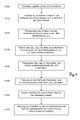
- FIG. 5 illustrates the autocollimation process according to the invention, in which a reference line is determined, which is perpendicular to a reflective surface of a Autokollimationsziels 6.
- the pixel coordinates (p x , p y ) of the center of the mirror image of the crosshairs are determined as shown FIG. 6b is apparent.
- This can be methods such as image processing by calculating the center of gravity of the crosshairs, an image comparison with stored patterns (pattern recognition) or others.
- the pixel displacement ⁇ p X and ⁇ p y that is, the distance between the pixel position 11 of the optical axis and the center of the crosshair 1 in pixels is determined as shown in FIG FIG. 6c is apparent.
- the pixel position 11 of the optical axis is known by a prior calibration of the telescope.
- the telescope is designed so that the pixel position 11 of the optical axis is located exactly in the middle of the sensor or in the middle of the image.
- the steps 120 to 150 can also be repeatedly executed until the determined angular differences ⁇ H and ⁇ V are smaller than predetermined threshold values, whereby an even higher accuracy in the determination of the reference line (ie a smaller residual deviation from the "ideal "Autocollimation") can be achieved.
- steps 120-150 for the first time - eg, due to insufficient camera calibration (such as distortion or translation of pixel locations in driveways) or positional inaccuracy after driving ⁇ H / 2 and ⁇ V / 2 - the crosshair center does not align with the optical axis in the image sufficiently exactly agrees (or the two crosshairs not yet sufficiently accurate in further iterations, these steps 120-150 may be repeated, respectively, until the desired residual deviation from the "ideal" autocollimation alignment is achieved.
- the inclination and orientation can also be determined by the in FIG. 7 procedure to be determined.
- the procedure is similar to steps 100 to 160 of FIG. 5
- S150 is skipped, ie it is not necessary to move the telescope.
- S180 the half angle differences ⁇ H / 2 and ⁇ V / 2 are added to the horizontal and vertical angles H and V measured in S160, and thus the inclination and the orientation of the autocollimation target 6 are detected.
- autocollimation operations can be performed in environments that are dangerous to humans and therefore inaccessible or restricted.
- the inserted telescope is provided with a motor for the adjustment movements of the telescope, and if the focus lens can also be moved by a motor, the otherwise manually performed steps can be carried out automatically, as shown in the following table.
- S100 may be performed automatically when the approximate position of the instrument and the autocollimation target 6 is known. However, S100 can also be automated in that the motorized telescope departs a given search pattern, and the autocollimation target 6 is detected by means of image recognition. For example, a mirror image of the telescope, which is reflected by the mirror attached to the autocollimation target, can serve as the comparison image.
- the corresponding directions of movement can be specified by arrows on the display or the screen of the control unit. Numerical values can also be displayed that represent the required amount of movement.
- FIG. 8a shows a further embodiment of a telescope, which can be used for autocollimation according to the invention.
- a telescope which can be used for autocollimation according to the invention.
- the illuminable crosshair 1 is arranged instead of on the optical axis between the illumination device 3 and the beam splitter 2.
- the crosshair 1 is illuminated directly and deflected the light beams 5 of the illuminated reticle 1 along the optical axis.
- the reflected light beams deflected by the second beam splitter 7 become the same as in the embodiment of FIG. 4 detected by the image sensor 8 and further processed accordingly.
- first reticle 1 which, for example, according to the variant of FIG. 8c can be formed
- second reticle 9 between the proximal end or the eyepiece of the telescope and the first beam splitter 2 is arranged on the optical axis, does not need to be illuminated and exemplified according to the variant FIG. 8b can be shaped
- a user can be facilitated or improved the manual Autokollimationsvorgang or an eye-check automatic autocollimation.
- the illuminated first crosshair 1 is thus not viewed directly or recorded by means of the camera sensor 8, but its mirror image, which is reflected at the collimation mirror, is picked up by the camera sensor 8 or viewed through the eyepiece.
- the unilluminated second reticle 9 the user looks directly through the eyepiece and it is - due to the Broberies - no mirror image of this second reticle 9 visible through the eyepiece.
- Neither the second reticle 9 itself nor its mirror image (second due to Brockbe criteria) are received by the camera sensor 8 (explaining this shows FIG. 8d an image from the perspective of the camera sensor, whereupon only the mirror image of the first reticle 1 appears and not just the second reticle 9 and not its mirror image).
- FIG. 8e shows the superimposable on the part of the user through the eyepiece of the mirror image of the first reticle 1 and the second reticle 9 in autocollimation orientation of the telescope.
- FIGS. 9a / b and 10 Another possible application of the automatic autocollimation process according to the invention in the form of stereo-photogrammetry is known from the FIGS. 9a / b and 10 can be seen.
- This method is used to determine objects in their position and exact form from two measurement images taken, for example, from slightly different points of view. It is possible to determine from which angle (orientation) images are taken.
- two instruments are aligned with each other so that the optical axes of their telescopes coincide, whereby the alignment of the two instruments can be determined.
- the distal ends of two telescopes 20, 30 are approximately aligned with each other. This corresponds to S200 in FIG. 10 .
- the first telescope 20 has at least the illumination device 3, the beam splitter 2, the illuminable crosshair 1, the displaceable focus lens 4 and the converging lens 10.
- the second telescope 30 likewise has a converging lens 10 and a displaceable focus lens 4.
- a second beam splitter 7th arranged, which is designed to deflect from the outside along the optical axis of the second telescope 30 incident light rays to an image sensor of an axis camera 8.
- the arrangement of the beam splitter 7 and the image sensor corresponds to that of the in FIG. 4 shown telescopes.
- a crosshair 15 is located between the second beam splitter 7 of the second telescope 30 and its proximal end.
- one of the two telescopes is adjusted by the calculated angle differences ⁇ H and ⁇ V, or both telescopes 20, 30 are adjusted by half the angular differences ⁇ H / 2 and ⁇ V / 2. By doing so, the two optical axes can be aligned parallel to each other.
- the two optical axes can be brought to coincidence, for example by the procedure described in more detail below.
- Both telescopes are - manually or motorized - focused on half the distance d / 2 between the telescopes (see the exemplary representation from FIG. 9b , which differ only in the focal positions of the two telescopes from the presentation FIG. 9a differs).
- the optical rays are now no longer parallel but focused on the object plane at half the distance.
- the two crosshairs are superimposed in the object plane and the horizontal and vertical offset can in turn be calculated using image processing.
- the pixel offset is converted into angular differences ( ⁇ H and ⁇ V), and the two telescopes adjusted by half of the horizontal and vertical angle differences ( ⁇ H / 2 and ⁇ V / 2) respectively.
- ⁇ H and ⁇ V angular differences
- ⁇ H / 2 and ⁇ V / 2 horizontal and vertical angle differences
- a collimated laser beam can also be used according to the invention, which is emitted parallel to or, ideally, along the optical axis of a telescope.
- the laser beam is reflected by the autocollimation target.
- the inclination and the orientation of the Autokollimationsziels are then determined.
- the deviation must be preceded by a previous one Calibration determined and then taken into account in the determination of the angle differences.
- the activities taking place according to the invention within the scope of the method can also be carried out in another order than the one shown by way of example.
- steps for reasons of handling
Priority Applications (9)
| Application Number | Priority Date | Filing Date | Title |
|---|---|---|---|
| EP10193428A EP2461132A1 (fr) | 2010-12-02 | 2010-12-02 | Télescope pour l'utilisation dans un instrument de mesure et procédé de collimation automatique automatisée d'un télescope d'un instrument de mesure ayant un objectif de collimation automatique |
| EP20110802009 EP2646771B1 (fr) | 2010-12-02 | 2011-12-02 | Instrument d'arpentage robotique et procédé pour l'autocollimation automatisée d'un télescope d'un instrument d'arpentage avec une cible d'autocollimation |
| AU2011334864A AU2011334864B9 (en) | 2010-12-02 | 2011-12-02 | Robotic surveying instrument and method for the automated autocollimation of a telescope of a surveying instrument comprising an autocollimation target |
| KR1020137014768A KR101520894B1 (ko) | 2010-12-02 | 2011-12-02 | 로봇식 측량 기계 및 오토콜리메이션 타겟을 포함하는 측량 기계의 망원경의 자동화된 오토콜리메이션을 위한 방법 |
| PCT/EP2011/071670 WO2012072811A1 (fr) | 2010-12-02 | 2011-12-02 | Instrument d'arpentage robotique et procédé pour l'autocollimation automatisée d'un télescope d'un instrument d'arpentage avec une cible d'autocollimation |
| BR112013012727A BR112013012727A2 (pt) | 2010-12-02 | 2011-12-02 | "instrumento de levantamento robótico e método para a autocolimação automática de um telescópio de um instrumento de levantamento compreendendo um alvo de autocolimação." |
| CA2819292A CA2819292C (fr) | 2010-12-02 | 2011-12-02 | Instrument d'arpentage robotique et procede pour l'autocollimation automatisee d'un telescope d'un instrument d'arpentage avec une cible d'autocollimation |
| US13/991,403 US9007573B2 (en) | 2010-12-02 | 2011-12-02 | Robotic surveying instrument and method for an automated collimation telescope and surveying instrument with and objective goal |
| CN201180057988.XA CN103261838B (zh) | 2010-12-02 | 2011-12-02 | 机器人测绘仪和包括自准直目标的用于测绘仪的望远镜的自动自准直的方法 |
Applications Claiming Priority (1)
| Application Number | Priority Date | Filing Date | Title |
|---|---|---|---|
| EP10193428A EP2461132A1 (fr) | 2010-12-02 | 2010-12-02 | Télescope pour l'utilisation dans un instrument de mesure et procédé de collimation automatique automatisée d'un télescope d'un instrument de mesure ayant un objectif de collimation automatique |
Publications (1)
| Publication Number | Publication Date |
|---|---|
| EP2461132A1 true EP2461132A1 (fr) | 2012-06-06 |
Family
ID=43877111
Family Applications (2)
| Application Number | Title | Priority Date | Filing Date |
|---|---|---|---|
| EP10193428A Withdrawn EP2461132A1 (fr) | 2010-12-02 | 2010-12-02 | Télescope pour l'utilisation dans un instrument de mesure et procédé de collimation automatique automatisée d'un télescope d'un instrument de mesure ayant un objectif de collimation automatique |
| EP20110802009 Active EP2646771B1 (fr) | 2010-12-02 | 2011-12-02 | Instrument d'arpentage robotique et procédé pour l'autocollimation automatisée d'un télescope d'un instrument d'arpentage avec une cible d'autocollimation |
Family Applications After (1)
| Application Number | Title | Priority Date | Filing Date |
|---|---|---|---|
| EP20110802009 Active EP2646771B1 (fr) | 2010-12-02 | 2011-12-02 | Instrument d'arpentage robotique et procédé pour l'autocollimation automatisée d'un télescope d'un instrument d'arpentage avec une cible d'autocollimation |
Country Status (8)
| Country | Link |
|---|---|
| US (1) | US9007573B2 (fr) |
| EP (2) | EP2461132A1 (fr) |
| KR (1) | KR101520894B1 (fr) |
| CN (1) | CN103261838B (fr) |
| AU (1) | AU2011334864B9 (fr) |
| BR (1) | BR112013012727A2 (fr) |
| CA (1) | CA2819292C (fr) |
| WO (1) | WO2012072811A1 (fr) |
Cited By (13)
| Publication number | Priority date | Publication date | Assignee | Title |
|---|---|---|---|---|
| CN103486998A (zh) * | 2013-09-18 | 2014-01-01 | 中国科学院西安光学精密机械研究所 | 自准直仪示值误差检定装置及检定方法 |
| CN106017363A (zh) * | 2016-08-07 | 2016-10-12 | 哈尔滨工业大学 | 一种高动态精度大工作距自准直装置与方法 |
| CN106052547A (zh) * | 2016-08-07 | 2016-10-26 | 哈尔滨工业大学 | 便携式组合调零高精度大工作距自准直装置与方法 |
| CN106052597A (zh) * | 2016-08-07 | 2016-10-26 | 哈尔滨工业大学 | 一种便携式高频响大工作距自准直装置与方法 |
| CN106225729A (zh) * | 2016-08-07 | 2016-12-14 | 哈尔滨工业大学 | 便携式组合调零高动态精度大工作距自准直装置与方法 |
| CN106247991A (zh) * | 2016-08-07 | 2016-12-21 | 哈尔滨工业大学 | 便携式组合调零激光大工作距自准直装置与方法 |
| CN106323199A (zh) * | 2016-08-07 | 2017-01-11 | 哈尔滨工业大学 | 组合调零激光大工作距自准直装置与方法 |
| CN106323200A (zh) * | 2016-08-07 | 2017-01-11 | 哈尔滨工业大学 | 自准直装置一种激光大工作距自准直装置与方法 |
| CN106323198A (zh) * | 2016-08-07 | 2017-01-11 | 哈尔滨工业大学 | 一种高精度、宽范围和大工作距激光自准直装置与方法 |
| CN106352814A (zh) * | 2016-08-07 | 2017-01-25 | 哈尔滨工业大学 | 阵列调零高动态精度大工作距自准直装置与方法 |
| CN106569342A (zh) * | 2016-11-07 | 2017-04-19 | 中国航空工业集团公司洛阳电光设备研究所 | 一种带有自准直功能的内调焦光管及使用方法 |
| DE102017129690A1 (de) | 2017-12-13 | 2019-06-13 | Valeo Schalter Und Sensoren Gmbh | Autokollimatoreinrichtung und deren Verwendung |
| CN114413931A (zh) * | 2021-12-31 | 2022-04-29 | 湖北省地震局(中国地震局地震研究所) | 一种水平准线陪检器i角测量方法 |
Families Citing this family (26)
| Publication number | Priority date | Publication date | Assignee | Title |
|---|---|---|---|---|
| CN103471562B (zh) * | 2013-09-09 | 2016-03-30 | 北京航天计量测试技术研究所 | 准平行光远距离动态重合度的自准直测量方法及装置 |
| CN103837143B (zh) * | 2014-03-25 | 2015-01-14 | 许凯华 | 一种超视瞄准测绘机 |
| CN103954434B (zh) * | 2014-04-16 | 2016-05-11 | 青岛歌尔声学科技有限公司 | 一种光轴校准治具、系统及方法 |
| CN103925880B (zh) * | 2014-04-29 | 2016-06-15 | 山东省计量科学研究院 | 用于剂量计检测的光学望远镜定位系统及其定位检测方法 |
| US20160109209A1 (en) | 2014-10-16 | 2016-04-21 | Ricky C. Ferguson | Lens for sighting device |
| CN104483757B (zh) * | 2014-11-20 | 2018-01-12 | 中国工程物理研究院激光聚变研究中心 | 离轴非球面元件精密定轴方法 |
| CN104483741B (zh) * | 2014-11-20 | 2017-07-18 | 中国工程物理研究院激光聚变研究中心 | 楔形透镜精密定轴方法 |
| EP3234675B1 (fr) | 2014-12-16 | 2021-11-24 | Ivan Arbouzov | Fixation de caméra modulaire pour dispositifs optiques |
| KR20160039588A (ko) | 2016-03-22 | 2016-04-11 | 주식회사 우리옵토 | 일정 곡률을 가지는 광학 렌즈상에 마이크로 패턴을 형성하는 방법 |
| NL2018376A (en) * | 2016-04-12 | 2017-10-17 | Asml Netherlands Bv | Mark Position Determination Method |
| CN106225731B (zh) * | 2016-08-07 | 2018-11-09 | 哈尔滨工业大学 | 组合调零高精度激光大工作距自准直装置与方法 |
| CN106248105B (zh) * | 2016-09-14 | 2023-04-11 | 中国科学院西安光学精密机械研究所 | 一种自准直经纬仪双照准差标定系统 |
| CN107543495B (zh) * | 2017-02-17 | 2019-02-22 | 北京卫星环境工程研究所 | 航天器设备自动准直测量系统、准直方法与测量方法 |
| US10408573B1 (en) | 2017-08-11 | 2019-09-10 | Douglas FOUGNIES | Vehicle-mounted device with network-connected scopes for allowing a target to be simultaneously tracked by multiple other devices |
| US10267598B2 (en) | 2017-08-11 | 2019-04-23 | Douglas FOUGNIES | Devices with network-connected scopes for allowing a target to be simultaneously tracked by multiple devices |
| CN109990735B (zh) * | 2018-12-29 | 2020-05-19 | 中国科学院西安光学精密机械研究所 | 用于提高自准直仪测量精度的光源频率调制装置及方法 |
| CN110231003A (zh) * | 2019-06-03 | 2019-09-13 | 深圳英飞拓智能技术有限公司 | 一种平整度测量装置 |
| CN110899960A (zh) * | 2019-11-21 | 2020-03-24 | 中国科学院西安光学精密机械研究所 | 一种螺旋扫描激光加工头平板玻璃的误差补偿方法 |
| CN111083470B (zh) * | 2019-12-30 | 2024-04-05 | 中国科学院西安光学精密机械研究所 | 一种阵列相机视轴调校装置及调校方法 |
| CN111637853B (zh) * | 2020-06-16 | 2021-09-24 | 河北汉光重工有限责任公司 | 一种大跨度t型转台光轴调校方法 |
| CN112325763B (zh) * | 2020-09-27 | 2022-02-01 | 中车唐山机车车辆有限公司 | 用于安装后应变计安装质量检测的检查装置及检查方法 |
| US11582375B2 (en) * | 2020-09-28 | 2023-02-14 | Argo AI, LLC | Enhanced pointing angle validation |
| CN113433711B (zh) * | 2021-05-13 | 2022-05-10 | 中国科学院西安光学精密机械研究所 | 一种基于TwinCAT Vision的二维镜架光路自动准直系统及方法 |
| DE102021120871B4 (de) * | 2021-08-11 | 2023-02-23 | Helmholtz-Zentrum Berlin für Materialien und Energie Gesellschaft mit beschränkter Haftung | Vorrichtung und Verfahren zur Justierung einer Achse |
| US20230221118A1 (en) * | 2022-01-07 | 2023-07-13 | Trimble Inc. | Total station with compensation for misaligned optical aiming point |
| CN114545645B (zh) * | 2022-02-28 | 2023-09-26 | 北京半导体专用设备研究所(中国电子科技集团公司第四十五研究所) | 一种潜望式集成光路的装调方法 |
Citations (5)
| Publication number | Priority date | Publication date | Assignee | Title |
|---|---|---|---|---|
| US3161715A (en) * | 1960-01-26 | 1964-12-15 | Davidson Optronics Inc | Autocollimator and automatic control means therefor |
| CH512057A (de) * | 1969-11-18 | 1971-08-31 | Grundig Emv | Verfahren zum Messen von Spiegelverkippungen |
| US5144479A (en) * | 1990-06-21 | 1992-09-01 | Yehudit Aharon | Combined telescope and autocollimator |
| EP0661519A1 (fr) * | 1993-12-28 | 1995-07-05 | Kabushiki Kaisha Topcon | Instrument d'arpentage |
| DE10235888A1 (de) * | 2001-08-10 | 2003-02-20 | Sokkia Co Ltd | Automatisch kollimierende Vermessungsvorrichtung mit Bildaufnahmevorrichtung |
Family Cites Families (10)
| Publication number | Priority date | Publication date | Assignee | Title |
|---|---|---|---|---|
| US4653911A (en) * | 1983-12-15 | 1987-03-31 | Fortin Michael A | Autocollimation method and apparatus |
| JP2826753B2 (ja) | 1989-12-14 | 1998-11-18 | 株式会社オプテック | 路面測定装置 |
| JPH11166831A (ja) * | 1997-12-04 | 1999-06-22 | Nikon Corp | レーザ測量システム |
| EP1314959A1 (fr) | 2001-11-22 | 2003-05-28 | Leica Geosystems AG | Dispositif électronique visualiseur et contrôleur pour appareil de mesure |
| CA2502012C (fr) | 2002-10-12 | 2012-07-10 | Leica Geosystems Ag | Dispositif d'affichage et de commande electronique destine a un appareil de mesure |
| US7027162B2 (en) * | 2004-08-16 | 2006-04-11 | Lau Kam C | System and method for three-dimensional measurement |
| US7835012B1 (en) * | 2007-05-01 | 2010-11-16 | Lockheed Martin Corporation | Alignment interferometer telescope apparatus and method |
| EP2053353A1 (fr) | 2007-10-26 | 2009-04-29 | Leica Geosystems AG | Procédé de mesure de la distance et appareil similaire |
| CN100580366C (zh) | 2008-03-03 | 2010-01-13 | 中国科学院光电技术研究所 | 一种检测大型望远镜主次镜间距的装置 |
| DE102008002241A1 (de) | 2008-06-05 | 2009-12-10 | Robert Bosch Gmbh | Verfahren und Messsystem zur bildbasierten Vermessung eines Raumes |
-
2010
- 2010-12-02 EP EP10193428A patent/EP2461132A1/fr not_active Withdrawn
-
2011
- 2011-12-02 US US13/991,403 patent/US9007573B2/en active Active
- 2011-12-02 WO PCT/EP2011/071670 patent/WO2012072811A1/fr active Application Filing
- 2011-12-02 EP EP20110802009 patent/EP2646771B1/fr active Active
- 2011-12-02 CA CA2819292A patent/CA2819292C/fr not_active Expired - Fee Related
- 2011-12-02 BR BR112013012727A patent/BR112013012727A2/pt active Search and Examination
- 2011-12-02 CN CN201180057988.XA patent/CN103261838B/zh active Active
- 2011-12-02 KR KR1020137014768A patent/KR101520894B1/ko active IP Right Grant
- 2011-12-02 AU AU2011334864A patent/AU2011334864B9/en not_active Ceased
Patent Citations (5)
| Publication number | Priority date | Publication date | Assignee | Title |
|---|---|---|---|---|
| US3161715A (en) * | 1960-01-26 | 1964-12-15 | Davidson Optronics Inc | Autocollimator and automatic control means therefor |
| CH512057A (de) * | 1969-11-18 | 1971-08-31 | Grundig Emv | Verfahren zum Messen von Spiegelverkippungen |
| US5144479A (en) * | 1990-06-21 | 1992-09-01 | Yehudit Aharon | Combined telescope and autocollimator |
| EP0661519A1 (fr) * | 1993-12-28 | 1995-07-05 | Kabushiki Kaisha Topcon | Instrument d'arpentage |
| DE10235888A1 (de) * | 2001-08-10 | 2003-02-20 | Sokkia Co Ltd | Automatisch kollimierende Vermessungsvorrichtung mit Bildaufnahmevorrichtung |
Cited By (25)
| Publication number | Priority date | Publication date | Assignee | Title |
|---|---|---|---|---|
| CN103486998A (zh) * | 2013-09-18 | 2014-01-01 | 中国科学院西安光学精密机械研究所 | 自准直仪示值误差检定装置及检定方法 |
| CN103486998B (zh) * | 2013-09-18 | 2016-09-07 | 中国科学院西安光学精密机械研究所 | 自准直仪示值误差检定方法 |
| CN106225729B (zh) * | 2016-08-07 | 2018-11-06 | 哈尔滨工业大学 | 便携式组合调零高动态精度大工作距自准直装置与方法 |
| CN106323198B (zh) * | 2016-08-07 | 2019-01-29 | 哈尔滨工业大学 | 一种高精度、宽范围和大工作距激光自准直装置与方法 |
| CN106017363A (zh) * | 2016-08-07 | 2016-10-12 | 哈尔滨工业大学 | 一种高动态精度大工作距自准直装置与方法 |
| CN106225729A (zh) * | 2016-08-07 | 2016-12-14 | 哈尔滨工业大学 | 便携式组合调零高动态精度大工作距自准直装置与方法 |
| CN106247991A (zh) * | 2016-08-07 | 2016-12-21 | 哈尔滨工业大学 | 便携式组合调零激光大工作距自准直装置与方法 |
| CN106323199A (zh) * | 2016-08-07 | 2017-01-11 | 哈尔滨工业大学 | 组合调零激光大工作距自准直装置与方法 |
| CN106323200A (zh) * | 2016-08-07 | 2017-01-11 | 哈尔滨工业大学 | 自准直装置一种激光大工作距自准直装置与方法 |
| CN106323198A (zh) * | 2016-08-07 | 2017-01-11 | 哈尔滨工业大学 | 一种高精度、宽范围和大工作距激光自准直装置与方法 |
| CN106352814A (zh) * | 2016-08-07 | 2017-01-25 | 哈尔滨工业大学 | 阵列调零高动态精度大工作距自准直装置与方法 |
| CN106247991B (zh) * | 2016-08-07 | 2018-11-06 | 哈尔滨工业大学 | 便携式组合调零激光大工作距自准直装置与方法 |
| CN106052597A (zh) * | 2016-08-07 | 2016-10-26 | 哈尔滨工业大学 | 一种便携式高频响大工作距自准直装置与方法 |
| CN106052547B (zh) * | 2016-08-07 | 2018-11-06 | 哈尔滨工业大学 | 便携式组合调零高精度大工作距自准直装置与方法 |
| CN106352814B (zh) * | 2016-08-07 | 2019-03-01 | 哈尔滨工业大学 | 阵列调零高动态精度大工作距自准直装置与方法 |
| CN106052597B (zh) * | 2016-08-07 | 2018-11-09 | 哈尔滨工业大学 | 一种便携式高频响大工作距自准直装置与方法 |
| CN106323199B (zh) * | 2016-08-07 | 2018-11-09 | 哈尔滨工业大学 | 组合调零激光大工作距自准直装置与方法 |
| CN106323200B (zh) * | 2016-08-07 | 2019-01-29 | 哈尔滨工业大学 | 一种激光大工作距自准直装置与方法 |
| CN106052547A (zh) * | 2016-08-07 | 2016-10-26 | 哈尔滨工业大学 | 便携式组合调零高精度大工作距自准直装置与方法 |
| CN106017363B (zh) * | 2016-08-07 | 2019-01-29 | 哈尔滨工业大学 | 一种高动态精度大工作距自准直装置与方法 |
| CN106569342A (zh) * | 2016-11-07 | 2017-04-19 | 中国航空工业集团公司洛阳电光设备研究所 | 一种带有自准直功能的内调焦光管及使用方法 |
| CN106569342B (zh) * | 2016-11-07 | 2019-04-16 | 中国航空工业集团公司洛阳电光设备研究所 | 一种带有自准直功能的内调焦光管及使用方法 |
| DE102017129690A1 (de) | 2017-12-13 | 2019-06-13 | Valeo Schalter Und Sensoren Gmbh | Autokollimatoreinrichtung und deren Verwendung |
| CN114413931A (zh) * | 2021-12-31 | 2022-04-29 | 湖北省地震局(中国地震局地震研究所) | 一种水平准线陪检器i角测量方法 |
| CN114413931B (zh) * | 2021-12-31 | 2023-12-22 | 湖北省地震局(中国地震局地震研究所) | 一种水平准线陪检器i角测量方法 |
Also Published As
| Publication number | Publication date |
|---|---|
| BR112013012727A2 (pt) | 2016-09-13 |
| AU2011334864B9 (en) | 2014-07-31 |
| US20130250284A1 (en) | 2013-09-26 |
| KR101520894B1 (ko) | 2015-05-18 |
| CA2819292C (fr) | 2016-05-10 |
| EP2646771A1 (fr) | 2013-10-09 |
| CA2819292A1 (fr) | 2012-06-07 |
| CN103261838B (zh) | 2016-09-14 |
| WO2012072811A1 (fr) | 2012-06-07 |
| AU2011334864A1 (en) | 2013-06-06 |
| CN103261838A (zh) | 2013-08-21 |
| EP2646771B1 (fr) | 2015-05-06 |
| KR20130085434A (ko) | 2013-07-29 |
| AU2011334864B2 (en) | 2014-07-03 |
| US9007573B2 (en) | 2015-04-14 |
Similar Documents
| Publication | Publication Date | Title |
|---|---|---|
| EP2646771B1 (fr) | Instrument d'arpentage robotique et procédé pour l'autocollimation automatisée d'un télescope d'un instrument d'arpentage avec une cible d'autocollimation | |
| EP2446300B1 (fr) | Procédé de suivi et système de mesure pourvu d'un appareil de suivi laser | |
| EP3264034B1 (fr) | Appareil de mesure avec système de mesure de hauteur et procédé de mesure d'une hauteur | |
| EP2810019B1 (fr) | Système de mesure doté d'un appareil de mesure et d'un module de balayage | |
| EP2787322B1 (fr) | Référencement géodésique de nuages de points | |
| EP2591311B1 (fr) | Appareil de mesure géodésique doté d'une fonction de ciblage de point cible haute précision et automatique | |
| DE102012011518B3 (de) | Geodätisches ziel und positionsbestimmungssystem | |
| EP2743728B1 (fr) | Procédé de suivi et système de mesure avec appareil de suivi laser | |
| EP2981787B1 (fr) | Appareil de mesure doté d'une fonction de calibrage d'une position d'image d'indication d'un réticule à croisillon électronique | |
| EP2737278B1 (fr) | Dispositif de mesure commandable sans contact et son procédé de commande | |
| EP2787321B1 (fr) | Détermination de surface d'objets à l'aide de la détermination d'un seul point précis géodésique et du balayage | |
| EP2353028B1 (fr) | Dispositif de détermination d'une position, et système de mesure géodésique | |
| EP3660451A1 (fr) | Module de stationnement intelligent | |
| EP2835613B1 (fr) | Appareil de mesure géodésique avec tableau de microlentilles | |
| EP2860550A1 (fr) | Scanner pour la mesure d'un espace | |
| EP1664674A1 (fr) | Procede et systeme de determination de la position spatiale d'un appareil de mesure portable | |
| EP2219011A1 (fr) | Appareil de mesure géodésique | |
| EP3479063B1 (fr) | Procede de comparaison d'un faisceau de reception se produisant sur un recepteur laser a l'aide d'un faisceau laser rotatif | |
| EP2936054A1 (fr) | Procédé et dispositif pour déterminer les coordonnées de lieu bidimensionnelles d'un objet cible | |
| EP2401576B1 (fr) | Appareil de nivellement et procédé de nivellement | |
| DE102016200877A1 (de) | System zum Messen einer dreidimensionalen Position | |
| EP2639615A1 (fr) | Caméra dotée d'un objectif à zoom et d'un encodeur linéaire | |
| DE102009019871B4 (de) | Hilfsvorrichtung zur Feinjustierung eines Laserstrahls auf einen vorgebbaren Zielpunkt |
Legal Events
| Date | Code | Title | Description |
|---|---|---|---|
| PUAI | Public reference made under article 153(3) epc to a published international application that has entered the european phase |
Free format text: ORIGINAL CODE: 0009012 |
|
| AK | Designated contracting states |
Kind code of ref document: A1 Designated state(s): AL AT BE BG CH CY CZ DE DK EE ES FI FR GB GR HR HU IE IS IT LI LT LU LV MC MK MT NL NO PL PT RO RS SE SI SK SM TR |
|
| AX | Request for extension of the european patent |
Extension state: BA ME |
|
| STAA | Information on the status of an ep patent application or granted ep patent |
Free format text: STATUS: THE APPLICATION IS DEEMED TO BE WITHDRAWN |
|
| 18D | Application deemed to be withdrawn |
Effective date: 20121207 |