EP2461023B1 - Rotor blade for a wind turbine and combination of a radar station and wind turbine - Google Patents
Rotor blade for a wind turbine and combination of a radar station and wind turbine Download PDFInfo
- Publication number
- EP2461023B1 EP2461023B1 EP11009519.7A EP11009519A EP2461023B1 EP 2461023 B1 EP2461023 B1 EP 2461023B1 EP 11009519 A EP11009519 A EP 11009519A EP 2461023 B1 EP2461023 B1 EP 2461023B1
- Authority
- EP
- European Patent Office
- Prior art keywords
- radar
- rotor blade
- thickness
- frequency
- composite fibre
- Prior art date
- Legal status (The legal status is an assumption and is not a legal conclusion. Google has not performed a legal analysis and makes no representation as to the accuracy of the status listed.)
- Active
Links
- 239000000835 fiber Substances 0.000 claims description 61
- 239000002131 composite material Substances 0.000 claims description 59
- 239000000463 material Substances 0.000 claims description 50
- 230000005855 radiation Effects 0.000 claims description 25
- 238000010276 construction Methods 0.000 claims description 21
- 239000011162 core material Substances 0.000 claims description 19
- 230000001419 dependent effect Effects 0.000 claims description 12
- 239000011343 solid material Substances 0.000 claims description 10
- 238000002310 reflectometry Methods 0.000 claims description 3
- 239000007787 solid Substances 0.000 claims 4
- 239000010410 layer Substances 0.000 description 28
- 239000006260 foam Substances 0.000 description 6
- 238000001514 detection method Methods 0.000 description 4
- 241000264877 Hippospongia communis Species 0.000 description 3
- 239000011159 matrix material Substances 0.000 description 3
- 230000000087 stabilizing effect Effects 0.000 description 3
- 102100040287 GTP cyclohydrolase 1 feedback regulatory protein Human genes 0.000 description 2
- 101710185324 GTP cyclohydrolase 1 feedback regulatory protein Proteins 0.000 description 2
- 238000005094 computer simulation Methods 0.000 description 2
- 239000012792 core layer Substances 0.000 description 2
- 230000001066 destructive effect Effects 0.000 description 2
- 230000000694 effects Effects 0.000 description 2
- 239000003822 epoxy resin Substances 0.000 description 2
- 239000002657 fibrous material Substances 0.000 description 2
- 239000003365 glass fiber Substances 0.000 description 2
- 229920000647 polyepoxide Polymers 0.000 description 2
- 241000771208 Buchanania arborescens Species 0.000 description 1
- 239000004698 Polyethylene Substances 0.000 description 1
- 229910000831 Steel Inorganic materials 0.000 description 1
- 239000004760 aramid Substances 0.000 description 1
- 229920006231 aramid fiber Polymers 0.000 description 1
- 230000015572 biosynthetic process Effects 0.000 description 1
- 239000004918 carbon fiber reinforced polymer Substances 0.000 description 1
- 239000004020 conductor Substances 0.000 description 1
- 238000013016 damping Methods 0.000 description 1
- 230000005611 electricity Effects 0.000 description 1
- 238000011156 evaluation Methods 0.000 description 1
- 239000004744 fabric Substances 0.000 description 1
- 230000002349 favourable effect Effects 0.000 description 1
- 239000011152 fibreglass Substances 0.000 description 1
- 239000002184 metal Substances 0.000 description 1
- 239000000615 nonconductor Substances 0.000 description 1
- 239000004033 plastic Substances 0.000 description 1
- 229920003023 plastic Polymers 0.000 description 1
- 229920001225 polyester resin Polymers 0.000 description 1
- 239000004645 polyester resin Substances 0.000 description 1
- -1 polyethylene Polymers 0.000 description 1
- 229920000573 polyethylene Polymers 0.000 description 1
- 238000004513 sizing Methods 0.000 description 1
- 239000010959 steel Substances 0.000 description 1
- 230000001629 suppression Effects 0.000 description 1
- 229920001169 thermoplastic Polymers 0.000 description 1
- 239000004416 thermosoftening plastic Substances 0.000 description 1
- 239000002023 wood Substances 0.000 description 1
Images

Classifications
-
- F—MECHANICAL ENGINEERING; LIGHTING; HEATING; WEAPONS; BLASTING
- F03—MACHINES OR ENGINES FOR LIQUIDS; WIND, SPRING, OR WEIGHT MOTORS; PRODUCING MECHANICAL POWER OR A REACTIVE PROPULSIVE THRUST, NOT OTHERWISE PROVIDED FOR
- F03D—WIND MOTORS
- F03D1/00—Wind motors with rotation axis substantially parallel to the air flow entering the rotor
- F03D1/06—Rotors
- F03D1/065—Rotors characterised by their construction elements
- F03D1/0675—Rotors characterised by their construction elements of the blades
-
- F—MECHANICAL ENGINEERING; LIGHTING; HEATING; WEAPONS; BLASTING
- F03—MACHINES OR ENGINES FOR LIQUIDS; WIND, SPRING, OR WEIGHT MOTORS; PRODUCING MECHANICAL POWER OR A REACTIVE PROPULSIVE THRUST, NOT OTHERWISE PROVIDED FOR
- F03D—WIND MOTORS
- F03D80/00—Details, components or accessories not provided for in groups F03D1/00 - F03D17/00
- F03D80/10—Arrangements for warning air traffic
-
- G—PHYSICS
- G01—MEASURING; TESTING
- G01S—RADIO DIRECTION-FINDING; RADIO NAVIGATION; DETERMINING DISTANCE OR VELOCITY BY USE OF RADIO WAVES; LOCATING OR PRESENCE-DETECTING BY USE OF THE REFLECTION OR RERADIATION OF RADIO WAVES; ANALOGOUS ARRANGEMENTS USING OTHER WAVES
- G01S13/00—Systems using the reflection or reradiation of radio waves, e.g. radar systems; Analogous systems using reflection or reradiation of waves whose nature or wavelength is irrelevant or unspecified
- G01S13/02—Systems using reflection of radio waves, e.g. primary radar systems; Analogous systems
- G01S13/50—Systems of measurement based on relative movement of target
- G01S13/52—Discriminating between fixed and moving objects or between objects moving at different speeds
-
- H—ELECTRICITY
- H01—ELECTRIC ELEMENTS
- H01Q—ANTENNAS, i.e. RADIO AERIALS
- H01Q15/00—Devices for reflection, refraction, diffraction or polarisation of waves radiated from an antenna, e.g. quasi-optical devices
- H01Q15/14—Reflecting surfaces; Equivalent structures
- H01Q15/16—Reflecting surfaces; Equivalent structures curved in two dimensions, e.g. paraboloidal
-
- F—MECHANICAL ENGINEERING; LIGHTING; HEATING; WEAPONS; BLASTING
- F05—INDEXING SCHEMES RELATING TO ENGINES OR PUMPS IN VARIOUS SUBCLASSES OF CLASSES F01-F04
- F05B—INDEXING SCHEME RELATING TO WIND, SPRING, WEIGHT, INERTIA OR LIKE MOTORS, TO MACHINES OR ENGINES FOR LIQUIDS COVERED BY SUBCLASSES F03B, F03D AND F03G
- F05B2260/00—Function
- F05B2260/99—Radar absorption
-
- F—MECHANICAL ENGINEERING; LIGHTING; HEATING; WEAPONS; BLASTING
- F05—INDEXING SCHEMES RELATING TO ENGINES OR PUMPS IN VARIOUS SUBCLASSES OF CLASSES F01-F04
- F05B—INDEXING SCHEME RELATING TO WIND, SPRING, WEIGHT, INERTIA OR LIKE MOTORS, TO MACHINES OR ENGINES FOR LIQUIDS COVERED BY SUBCLASSES F03B, F03D AND F03G
- F05B2280/00—Materials; Properties thereof
- F05B2280/60—Properties or characteristics given to material by treatment or manufacturing
- F05B2280/6003—Composites; e.g. fibre-reinforced
-
- Y—GENERAL TAGGING OF NEW TECHNOLOGICAL DEVELOPMENTS; GENERAL TAGGING OF CROSS-SECTIONAL TECHNOLOGIES SPANNING OVER SEVERAL SECTIONS OF THE IPC; TECHNICAL SUBJECTS COVERED BY FORMER USPC CROSS-REFERENCE ART COLLECTIONS [XRACs] AND DIGESTS
- Y02—TECHNOLOGIES OR APPLICATIONS FOR MITIGATION OR ADAPTATION AGAINST CLIMATE CHANGE
- Y02E—REDUCTION OF GREENHOUSE GAS [GHG] EMISSIONS, RELATED TO ENERGY GENERATION, TRANSMISSION OR DISTRIBUTION
- Y02E10/00—Energy generation through renewable energy sources
- Y02E10/70—Wind energy
- Y02E10/72—Wind turbines with rotation axis in wind direction
Definitions
- the present invention relates to a rotor blade for a wind power plant, comprising a shell structure of flat fiber composite material forming the rotor blade surface. Furthermore, the invention relates to a combination of a radar station and a wind turbine arranged in the reception area of the radar station.
- Wind turbines comprise a rotatably mounted rotor structure, which is typically formed by a rotatably mounted rotor shaft, a rotor hub at one end of the rotor shaft and one or more radially projecting from the rotor hub rotor blades (rotor blades).
- the rotor shaft is rotatably mounted about a horizontal axis in a machine housing ("gondola”), which in turn is arranged rotatably about a vertical axis on a vertically towering tower.
- a machine housing gondola
- Such wind turbines generate radar reflections on the tower, on the machine housing and on the rotor structure, in particular the rotor blades, upon irradiation of electromagnetic waves by radar systems.
- the extent of the back reflection of radar radiation at the rotor structure or its rotor blades and the Doppler shift of the radar reflection depend on the direction of incidence of the radar radiation and the rotational position or rotational speed of the rotor structure. In a radar system with moving target detection, which evaluates such Doppler shifts, this may undesirably lead to corresponding parts of the rotor structure, ie z. B. rotor blades are misinterpreted as "flying objects". If in this way wind turbines are imaged on the radar screen of the radar system as an additional target, this can make the recognition of the desired goals sometimes considerably more difficult. Such goals can z. As aircraft in an air surveillance radar, rain clouds in a weather radar or ships in a maritime navigation radar.
- Rotor blades are known from the prior art, which are characterized by radar-absorbing or radar-reflecting structures (see, eg WO 2009/140949 ; WO 2010/122352 ; US 2923934 ).
- This object is achieved by the rotor blade according to claim 1.
- the front edge and the trailing edge of the rotor blade represent those surface sections whose radar reflections have the greatest potential for the operation of radar systems with regard to the Doppler effect.
- the inventive design of the fiber composite material at least in these areas of the shell structure of the rotor blade, namely with a Radarreflexions tint (damping factor) in the frequency range for incident perpendicular to the surface radar radiation has a reflection minimum, a considerable reduction in interference.
- the rotor blade according to the invention may have a basic structure similar to known in the prior art rotor blades, namely z. B. composed of two half-shells, each made of a fiber composite material (eg., Multilayer GRP laminate) are made and glued to each other at the front and rear edges of the rotor blade. Accordingly, it is provided according to an embodiment of the invention that the rotor blade is formed from a plurality of interconnected, in particular glued together shell shells.
- a fiber composite material eg., Multilayer GRP laminate
- two half shells may be provided, which are connected to each other at the front and rear edges of the rotor blade.
- a fiber composite solid material can be a suitable dimensioning rule z.
- d V ⁇ 0 2 ⁇ V
- At least one web which is arranged in the interior of the jacket structure and stabilizes the jacket structure.
- One or more such webs may, for. Example, be formed of sheet-like fiber composite material, which is preferably also designed to provide a frequency-dependent radar reflection factor for incident perpendicular to the surface radar radiation with a reflection minimum at a specific frequency in the range of 1 GHz to 10 GHz.
- the frequency of the radar radiation may be identical or at least substantially identical (eg, less than 10% different than) that frequency for which the fiber composite material at the leading and trailing edges of the rotor blade (and optionally the web or webs) Has reflection minimum.
- the fiber composite material provided for providing the reflection minimum is formed as a fiber composite material.
- this fiber composite material may be formed in sandwich construction comprising a plurality of (identical or different) fiber composite layers.
- z. B. a symmetrical sandwich construction can be used.
- a fiber composite solid material may, for. B. as a laminate comprising a plurality of identical fiber material layers (eg., Weave, braids, scrim, etc.) may be formed.
- a simple sandwich construction sees a core layer z.
- foam plastic in particular hard foam, or wood, especially light wood, or a honeycomb or wave structure (eg., From a resin-impregnated paper or eg a GRP material (eg, containing a glass fiber fabric)), and On both sides thereof arranged cover layers of similar or different types of fiber composite layers (eg., GFRP etc.) before.
- the fiber composite material used to provide said reflection minimum at the leading and trailing edges of the rotor blade particularly preferably has a low electrical conductivity, be it in total (over the entire thickness of the sheath structure) or at least in a near-surface and thus the surface at the leading and trailing edge forming Area.
- a construction reduces the reflection of incident radar energy.
- most of the radar energy is passed through the shell structure of the rotor blade. In this way, the rotor blade is quasi more or less transparent for a large part of the incident radar energy, so that only a relatively small proportion of energy from the rotor blade to the radar system are reflected back, which further reduces the interference of the radar operation.
- fiber composite materials preferred for forming the sheath structure at least at the leading and trailing edges of the rotor blade and / or for forming the stabilizing web (s) are those which conduct electricity poorly (eg materials having an electrical loss factor "tan ⁇ "). less than 0.01) or as electrical non-conductors (e.g. B. materials with an electrical loss factor "tan ⁇ of less than 0.001) are to be regarded.
- a fiber material consisting of electrically non-conductive fibers such.
- electrically non-conductive fibers such as glass fibers, aramid fibers, polyethylene fibers, etc. are used, this in conjunction with an electrically non-conductive matrix such.
- epoxy resin polyester resin, etc.
- individual layers can also z. B. may be formed from the aforementioned rigid foams, etc.
- the "first layer" of the flat fiber composite material which is thus hit directly by the incident radar radiation, is formed from an electrically poor or non-conductive fiber composite material.
- CFK is here due to its relatively high electrical conductivity rather unfavorable, and instead z.
- fiberglass to prefer.
- the "geometry" of the flat fiber composite material used to form the leading and trailing edges of the rotor blade (or of the web or webs) is of great importance.
- this fiber composite material is formed as a fiber composite solid material, as well as when this fiber composite material is formed in sandwich construction comprising a plurality of fiber composite layers, there are always several interfaces between viewed in Radarstrahlungsraum immediately adjacent material layers or between such a material layer and air (on the outside or the inside of the shell structure of the rotor blade).
- the invention provided reflection minimum can be realized in a simple manner that the radar radiation components reflected back from the various interfaces substantially destructive interfere.
- suitable material combinations or material arrangements can, for. B., taking into account the above-described "sizing" are set.
- the above formulas given values for the thickness of a solid material (d V ) and the thickness of the core material (d K ) in a symmetrical sandwich construction are preferably at least approximately provided, for. B. with a deviation between the actual thickness and the given formula given thickness of less than 10%, in particular less than 5%, in the relevant material (fiber composite solid material or core material) resulting wavelength of the radar radiation.
- the fiber composite material provided for providing the reflection minimum has an electrical surface resistivity of more than 10 3 ohms / square.
- the reflection minimum has a value of less than -20 dB, in particular less than -25 dB.
- the reflection minimum has a value of less than -20 dB, in particular less than -25 dB.
- the position of the reflection minimum provided according to the invention is to be adapted as precisely as possible to the frequency of the radar radiation to be expected in the use of the rotor blade. If the frequency of the reflection minimum deviates appreciably from this radar frequency, the radar frequency is still preferably within the half-width of the reflection minimum.
- the frequency-dependent reflection factor in the frequency range from 1 GHz to 10 GHz has exactly one minimum.
- more than a minimum of the reflection factor may be provided in this frequency range, in particular z. B. exactly two minima. In the latter case, the location of the two minima z. B. be adapted to two different radar frequencies of two different radar systems (eg., An air surveillance radar and a weather radar).
- a combination (at least) of a radar station and a wind turbine disposed in the receiving area of the radar station wherein rotor blades of the wind turbine are each formed as a rotor blade according to one of claims 1-3 the frequency of the reflection minimum corresponds to the radar frequency of the radar station.
- Any deviation between the frequency of the reflection minimum and the radar frequency is preferably less than 0.5 GHz.
- the reflection factor at the radar frequency is preferably less than -15 dB, more preferably less than -20 dB.
- the combination comprises two radar stations with mutually different radar frequencies, z.
- the created with the fiber composite frequency-dependent radar reflection factor has two reflection minima of the type explained, the frequencies of which correspond to the radar frequencies of the radar stations. This possibly again with at most rather small deviations, as already described for the case of a radar station and a reflection minimum.
- Each radar station may in particular be a radar station with moving-target detection by evaluating a Doppler shift of the back-reflected radar signal.
- the combination comprises a plurality of radar stations with mutually different radar frequencies
- at least one frequency pair exists among the radar frequencies, in which one radar frequency is an integer multiple of the other radar frequency.
- An example of this is an air traffic control radar with a radar frequency of 3 GHz in combination with a maritime navigation radar with a radar frequency of 9 GHz.
- Fig. 1 illustrates in a sectional view the structure of a rotor blade 10 for a wind turbine, comprising a shell structure 12 and a shell structure 12 stabilizing internal structure 14, which in the illustrated embodiment is formed by two transverse to the direction of extension of the rotor blade profile webs 14-1 and 14-2.
- the rotor blade 10 has a front edge 16 and a rear edge 18.
- the outside of the shell structure 12 defines the surface 20 of the rotor blade 10 and the shell structure 12 is formed of flat fiber composite material, wherein in the illustrated embodiment, two different areas or different fiber composite materials 12-1 and 12-2 are used.
- the material is 12-1 is used to form the leading edge 16 and the adjoining shell structure areas to about the center of the illustrated rotor blade 10 (beyond the webs 14-1, 14-2).
- the material 12-2 is provided to form the underlying areas of the rotor blade 10 up to the trailing edge 18.
- the webs 14-1, 14-2 are each formed of (identical) fiber composite material, which, however, differs from the flat fiber composite materials 12-1 and 12-2.
- a special feature of the rotor blade 10 is that at least at the front edge 16 and the trailing edge 18, in the example shown in the region of the webs 14-1, 14-2, the respective fiber composite material 12-1 and 12-2 (and in the example shown Also, the fiber composite materials 14-1, 14-2) is designed to provide a frequency-dependent radar reflection factor R for perpendicular to the surface incident electromagnetic radar radiation with a reflection minimum at a specific frequency in the range of 1 GHz to 10 GHz.
- Fig. 2, 3 and 4 show the respective constructions of the flat fiber composite materials 12-1, 12-2 and 14-1, 14-2, respectively.
- the fiber composite material 12-1 ( Fig. 2 ) has a monolithic GRP construction, ie consists of a layer of GRP material, with a thickness of 12.9 mm.
- the dielectric constant of the GFRP material 12-1 is about 4.3.
- the fiber composite material 12-2 ( Fig. 3 ) is a sandwich construction of an outer GRP cover layer 22 (thickness 1 mm, dielectric constant 4.3), an inner GRP cover layer 24 (thickness 1 mm, dielectric constant 4.3), and a hard foam core 26 (thickness 11.3 mm, dielectric constant 1.1).
- the fiber composite material 14-1, 14-2 (FIG. Fig. 4 ) is also a sandwich construction of an outer GRP cover layer 22 '(thickness 2 mm, dielectric constant 4.3), an inner GRP cover layer 24' (thickness 2 mm, dielectric constant 4.3), and a hard foam core 26 '( Thickness 8.5 mm, dielectric constant 1.1).
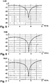
- FIGS. 5, 6 and 7 are the calculated frequency - dependent reflection factor curves in the Fig. 2, 3 and 4 represented fiber composite materials at normal incidence of radiation.
- Fig. 5 shows the reflection factor R for the fiber composite material 12-1.
- Fig. 6 shows the reflection factor R for the fiber composite material 12-2.
- Fig. 7 shows the reflection factor R for the fiber composite 14-1, 14-2.
- the half-value widths of the reflection minima lying at 5.6 GHz are each less than 0.5 GHz.
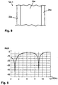
- Fig. 8 illustrates another example of a construction suitable for reducing radar reflections and shows a sectional view of a sheet-like fiber composite material 12a-1.
- the fiber composite material 12a-1 may, for. B. in a rotor blade of Fig. 1 shown type as a substitute for one or more of the fiber composite materials used there 12-1, 12-2 and 14-1, 14-2 are used.
- the in Fig. 8 represented fiber composite material 12a-1 for the entire shell structure (and the optionally provided internal structure) of such a rotor blade of in Fig. 1 used type shown.
- the fiber composite material 12a-1 is a sandwich construction of an outer GRP cover layer 22a (thickness 3 mm, dielectric constant 4.3), an inner GRP cover layer 24a (thickness 3 mm, dielectric constant 4.3), and a honeycomb core 26 '. made of resin-impregnated paper (thickness 17.5 mm, dielectric constant 1.07).
- a special feature of the fiber composite material 12a-1 is that its frequency-dependent radar reflection factor R for radar radiation incident perpendicular to the surface has two reflection minima at certain frequencies in the range of 1 GHz to 10 GHz.
- these reflection minima are at the frequencies of 3 GHz (eg frequency of a military air traffic control radar) and at 9 GHz (eg frequency of a maritime navigation radar). At these frequencies, a significant reduction in radar reflectivity is achieved, namely at 0.001% (at 3 GHz) and 0.02% (at 9 GHz).
- a rotor blade for a wind turbine can be realized in which the radar reflections are significantly reduced.
- the reflection-minimized fiber composite material is used at least at the leading edge and the trailing edge of the rotor blade.
- Radar frequencies can be adapted to the particular arrangement and combination of materials and their dimensions, layer thickness (s) and electromagnetic material constants.
- metallic conductors must be provided to z. B. from the rotor blade tip or the rotor blade surface lightning currents in the direction of the earth (eg., Via a machine housing and a tower) to dissipate.
- epoxy resin as the matrix is often preferred in the fiber composite materials described, other matrix materials such. As thermoplastics in question.
Landscapes
- Engineering & Computer Science (AREA)
- Radar, Positioning & Navigation (AREA)
- Remote Sensing (AREA)
- Physics & Mathematics (AREA)
- Chemical & Material Sciences (AREA)
- Combustion & Propulsion (AREA)
- Mechanical Engineering (AREA)
- General Engineering & Computer Science (AREA)
- Life Sciences & Earth Sciences (AREA)
- Sustainable Energy (AREA)
- Sustainable Development (AREA)
- Computer Networks & Wireless Communication (AREA)
- General Physics & Mathematics (AREA)
- Electromagnetism (AREA)
- Radar Systems Or Details Thereof (AREA)
- Wind Motors (AREA)
Description
Die vorliegende Erfindung betrifft ein Rotorblatt für eine Windenergieanlage, umfassend eine die Rotorblattoberfläche ausbildende Mantelstruktur aus flächigem Faserverbundmaterial. Ferner betrifft die Erfindung eine Kombination einer Radarstation und einer im Empfangsbereich der Radarstation angeordneten Windenergieanlage.The present invention relates to a rotor blade for a wind power plant, comprising a shell structure of flat fiber composite material forming the rotor blade surface. Furthermore, the invention relates to a combination of a radar station and a wind turbine arranged in the reception area of the radar station.
Windenergieanlagen umfassen eine drehbar gelagerte Rotorstruktur, die typischerweise von einer drehbar gelagerten Rotorwelle, einer Rotornabe an einem Ende der Rotorwelle und einem oder mehreren in Radialrichtung von der Rotornabe abstehenden Rotorblättern (Rotorflügeln) gebildet ist.Wind turbines comprise a rotatably mounted rotor structure, which is typically formed by a rotatably mounted rotor shaft, a rotor hub at one end of the rotor shaft and one or more radially projecting from the rotor hub rotor blades (rotor blades).
Bei einem sehr weit verbreiteten Anlagentyp ist die Rotorwelle um eine Horizontalachse drehbar in einem Maschinengehäuse ("Gondel") gelagert, welches wiederum um eine Vertikalachse drehbar an einem vertikal aufragenden Turm angeordnet ist.In a very widespread type of system, the rotor shaft is rotatably mounted about a horizontal axis in a machine housing ("gondola"), which in turn is arranged rotatably about a vertical axis on a vertically towering tower.
Derartige Windenergieanlagen erzeugen bei Bestrahlung von elektromagnetischen Wellen durch Radarsysteme Radarreflexionen am Turm, am Maschinengehäuse und an der Rotorstruktur, insbesondere den Rotorblättern.Such wind turbines generate radar reflections on the tower, on the machine housing and on the rotor structure, in particular the rotor blades, upon irradiation of electromagnetic waves by radar systems.
Wenngleich mittels der in vielen Radarsystemen vorgesehenen Festzielunterdrückung die zeitlich überwiegend konstanten Radarreflexionen am Turm und am Maschinengehäuse bei der Auswertung der rückreflektierten Radarstrahlung wirksam ausgeblendet werden können, so stellen die Rotorblätter aufgrund ihrer Drehung und der damit einhergehenden Dopplerverschiebung der an ihnen reflektierten Radarstrahlung ein hohes Störpotential für den Betrieb von Radarsystemen mit Bewegtzielerkennung dar.Although by means of the fixed target suppression provided in many radar systems, the predominantly constant radar reflections on the tower and on the machine housing can be effectively masked out in the evaluation of the reflected radar radiation, the rotor blades, due to their rotation and the associated Doppler shift, reflect the reflectors reflected therefrom Radar radiation is a high potential for the operation of radar systems with moving target detection.
Das Ausmaß der Rückreflexion von Radarstrahlung an der Rotorstruktur bzw. deren Rotorblättem sowie die Dopplerverschiebung der Radarreflexion hängen von der Einfallsrichtung der Radarstrahlung und der Drehstellung bzw. Drehgeschwindigkeit der Rotorstruktur ab. Bei einem Radarsystem mit Bewegtzielerkennung, welches derartige Dopplerverschiebungen auswertet, kann dies unerwünschterweise dazu führen, dass entsprechende Teile der Rotorstruktur, also z. B. Rotorblätter als "Flugobjekte" fehlinterpretiert werden. Wenn in dieser Weise Windenergieanlagen auf dem Radarschirm des Radarsystems als zusätzliches Ziel abgebildet werden, so kann dies die Erkennung der gewünschten Ziele teilweise erheblich erschweren. Solche Ziele können z. B. Flugzeuge bei einem Luftüberwachungsradar, Regenwolken bei einem Wetterradar oder auch Schiffe bei einem maritimen Navigationsradar sein.The extent of the back reflection of radar radiation at the rotor structure or its rotor blades and the Doppler shift of the radar reflection depend on the direction of incidence of the radar radiation and the rotational position or rotational speed of the rotor structure. In a radar system with moving target detection, which evaluates such Doppler shifts, this may undesirably lead to corresponding parts of the rotor structure, ie z. B. rotor blades are misinterpreted as "flying objects". If in this way wind turbines are imaged on the radar screen of the radar system as an additional target, this can make the recognition of the desired goals sometimes considerably more difficult. Such goals can z. As aircraft in an air surveillance radar, rain clouds in a weather radar or ships in a maritime navigation radar.
Bei einem Betrieb von mehreren, räumlich zu einem "Windpark" zusammengefassten Windenergieanlagen treten die durch die einzelnen Windenergieanlagen verursachten Störziele in einem größeren, meist mehrere Quadratkilometer umfassenden Flächenbereich auf, in dem dann eine eindeutige Identifizierung und Verfolgung der gewünschten Ziele oftmals nicht mehr möglich ist. Aus dem Stand der Technik sind Rotorblätter bekannt, die sich durch radarabsorbierende oder radarreflektierende Strukturen auszeichnen (siehe z.B.
Es ist eine Aufgabe der vorliegenden Erfindung, durch den Betrieb einer Windkraftanlage bzw. eines Windparks hervorgerufene Störungen von Radarsystemen zu verringern. Diese Aufgabe wird durch das Rotorblatt nach Anspruch 1 gelöst. Die Vorderkante und die Hinterkante des Rotorblattes stellen diejenigen Oberflächenabschnitte dar, deren Radarreflexionen im Hinblick auf den Dopplereffekt das größte Störpotential für den Betrieb von Radarsystemen besitzen.It is an object of the present invention to reduce disturbances of radar systems caused by the operation of a wind turbine or a wind farm. This object is achieved by the rotor blade according to
Somit gewährleistet die erfindungsgemäße Gestaltung des Faserverbundmaterials zumindest in diesen Bereichen der Mantelstruktur des Rotorblattes, nämlich mit einem Radarreflexionsfaktor (Dämpfungsfaktor) der im genannten Frequenzbereich für senkrecht zur Oberfläche einfallende Radarstrahlung ein Reflexionsminimum aufweist, eine beträchtliche Verringerung der Störungen.Thus, the inventive design of the fiber composite material at least in these areas of the shell structure of the rotor blade, namely with a Radarreflexionsfaktor (damping factor) in the frequency range for incident perpendicular to the surface radar radiation has a reflection minimum, a considerable reduction in interference.
Das erfindungsgemäße Rotorblatt kann eine grundsätzliche Struktur ähnlich wie bei nach dem Stand der Technik bekannten Rotorblättern besitzen, nämlich z. B. aus zwei Halbschalen zusammengesetzt, die jeweils aus einem Faserverbundwerkstoff-Vollmaterial (z. B. mehrschichtiges GFK-Laminat) hergestellt sind und an den Vorder- und Hinterkanten des Rotorblattes miteinander verklebt sind. Dementsprechend ist gemäß einer Ausführungsform der Erfindung vorgesehen, dass das Rotorblatt aus mehreren miteinander verbundenen, insbesondere miteinander verklebten Mantelschalen gebildet ist.The rotor blade according to the invention may have a basic structure similar to known in the prior art rotor blades, namely z. B. composed of two half-shells, each made of a fiber composite material (eg., Multilayer GRP laminate) are made and glued to each other at the front and rear edges of the rotor blade. Accordingly, it is provided according to an embodiment of the invention that the rotor blade is formed from a plurality of interconnected, in particular glued together shell shells.
Beispielsweise können zwei Halbschalen vorgesehen sein, die an den Vorder- und Hinterkanten des Rotorblattes miteinander verbunden sind.For example, two half shells may be provided, which are connected to each other at the front and rear edges of the rotor blade.
Bei der Erfindung wird jedoch bei der konkreten Materialauswahl und den geometrischen Verhältnissen (z. B. Materialdicke, bzw. Schichtdicken bei mehrschichtigem Material) dafür Sorge getragen, dass sich das genannte Reflexionsminimum ergibt.In the case of the invention, however, the concrete material selection and the geometrical conditions (eg material thickness, or layer thicknesses in the case of multi-layered material) Material) to ensure that said reflection minimum results.
Im Falle eines Faserverbund-Vollmaterials lässt sich eine hierfür geeignete Dimensionierungsregel z. B. mit folgender Formel ausdrücken: 
Dabei bedeutet:
- dV :
- Dicke des Vollmaterials
- λ0 :
- Freiraum-Wellenlänge des Radarsystems
- εV :
- Spezifische Dielektrizitätskonstante (Realteil) des Vollmaterials
- dv :
- Thickness of the solid material
- λ 0 :
- Free space wavelength of the radar system
- ε V :
- Specific dielectric constant (real part) of the solid material
Mit der Dicke dv des Vollmaterials ergibt sich ein Reflexionsminimum für die Frequenz f0 = c/λ0 des Radarsystems (mit c = Lichtgeschwindigkeit) und für ganzzahlige Vielfache davon, wobei die ganzen Zahlen ungerade sind.The thickness d v of the solid material results in a reflection minimum for the frequency f 0 = c / λ 0 of the radar system (with c = speed of light) and for integer multiples thereof, the whole numbers being odd.
Im Falle einer Sandwich-Bauweise umfassend wenigstens eine Kemwerkstoff-Schicht und wenigstens zwei Deckschichten können ähnliche Dimensionierungsregeln zur Erzielung des gewünschten Reflexionsminimums berücksichtigt werden. Beispielsweise für den Fall eines symmetrischen Sandwich-Aufbaus, worunter eine Bauweise zu verstehen ist, die vorn und hinten Schichten gleicher Dicke und gleichen Materials besitzt, mit einem dazwischenliegenden Kemwerkstoff, lässt sich eine geeignete Dimensionierung z. B. wie folgt festlegen:
- Sobald aus mechanischen Gründen die Materialien der Deckschichten und des Kernwerkstoffes sowie die Dicken der faserverstärkten Deckmaterialien definiert worden sind, ergibt sich die Dicke des Kernwerkstoffes näherungsweise aus folgender Formel:

- Once defined for mechanical reasons, the materials of the outer layers and the core material and the thicknesses of the fiber-reinforced cover materials have been made, the thickness of the core material is approximately the following formula:
Dabei bedeutet:
- dK :
- Dicke des Kernwerkstoffes
- λ0 :
- Freiraum-Wellenlänge des Radarsystems
- εK :
- Spezifische Dielektrizitätskonstante (Realteil) des Kernwerkstoffes
- dD :
- Dicke des Deckschichtmaterials
- εD :
- Spezifische Dielektrizitätskonstante (Realteil) des Deckschicht-Materials
- d K :
- Thickness of the core material
- λ 0 :
- Free space wavelength of the radar system
- ε K :
- Specific dielectric constant (real part) of the core material
- dd :
- Thickness of the cover layer material
- ε D :
- Specific dielectric constant (real part) of the cover layer material
Besonders bevorzugt werden hierbei folgende Einschränkungen beachtet:
- a) εK ≤1,8 d.h. die spezifische Dielektrizitätskonstante des Kernwerkstoffes sollte unter
dem Wert - b)

- a) ε K ≤1.8 ie the specific dielectric constant of the core material should be less than 1.8. This is true for most foams, honeycombs, etc.
- b)
Mit der vorgegebenen Dicke und der spezifischen Dielektrizitätskonstante des Deckschichtmaterials sowie der vorgegebenen spezifischen Dielektrizitätskonstante des Kernwerkstoffes ergibt sich also mit obiger Formel näherungsweise die Dicke des Kernwerkstoffes, bei der der Reflexionsfaktor für die Frequenz f0 = c/λ0 des Radarsystems (mit c = Lichtgeschwindigkeit) minimal wird.With the predetermined thickness and the specific dielectric constant of the cover layer material and the specified specific dielectric constant of the core material thus results with the above formula approximately the thickness of the core material, in which the reflection factor for the frequency f 0 = c / λ 0 of the radar system (with c = speed of light) is minimal.
Mit Hilfe einer Computersimulation kann, ausgehend von diesem Startwert, auch noch eine "Feinjustierung" der Kernschichtdicke erfolgen, so dass das Reflexionsminimum genau auf die Frequenz des Radarsystems abgestimmt wird.With the aid of a computer simulation, starting from this starting value, a "fine adjustment" of the core layer thickness can also take place, so that the reflection minimum is tuned exactly to the frequency of the radar system.
Ähnlich wie an sich bereits aus dem Stand der Technik bekannt, kann auch bei dem erfindungsgemäßen Rotorblatt dessen Stabilität durch mindestens einen im Innenraum der Mantelstruktur angeordneten, die Mantelstruktur stabilisierenden Steg verbessert werden. Ein oder mehrere solche Stege können z. B. aus flächigem Faserverbundmaterial gebildet sein, welches bevorzugt ebenfalls zur Schaffung eines frequenzabhängigen Radarreflexionsfaktors für senkrecht zur Oberfläche einfallende Radarstrahlung mit einem Reflexionsminimum bei einer bestimmten Frequenz im Bereich von 1 GHz bis 10 GHz ausgebildet ist.Similar to what is already known from the prior art, its stability can also be improved in the rotor blade according to the invention by at least one web which is arranged in the interior of the jacket structure and stabilizes the jacket structure. One or more such webs may, for. Example, be formed of sheet-like fiber composite material, which is preferably also designed to provide a frequency-dependent radar reflection factor for incident perpendicular to the surface radar radiation with a reflection minimum at a specific frequency in the range of 1 GHz to 10 GHz.
Die Frequenz der Radarstrahlung kann identisch oder zumindest im Wesentlichen identisch (z. B. um weniger als 10 % abweichend von) derjenigen Frequenz sein, für welche das Faserverbundmaterial an den Vorder- und Hinterkanten des Rotorblattes (und gegebenenfalls des oder der Stege) das genannte Reflexionsminimum besitzt.The frequency of the radar radiation may be identical or at least substantially identical (eg, less than 10% different than) that frequency for which the fiber composite material at the leading and trailing edges of the rotor blade (and optionally the web or webs) Has reflection minimum.
In einer Ausführungsform ist vorgesehen, dass das zur Bereitstellung des Reflexionsminimums vorgesehene Faserverbundmaterial als ein Faserverbundwerkstoff-Vollmaterial ausgebildet ist. Alternativ kann dieses Faserverbundmaterial in Sandwich-Bauweise umfassend mehrere (gleich- oder verschiedenartige) Faserverbundwerkstoff-Schichten ausgebildet sein. Insbesondere kann z. B. ein symmetrischer Sandwich-Aufbau verwendet werden.In one embodiment, it is provided that the fiber composite material provided for providing the reflection minimum is formed as a fiber composite material. Alternatively, this fiber composite material may be formed in sandwich construction comprising a plurality of (identical or different) fiber composite layers. In particular, z. B. a symmetrical sandwich construction can be used.
Ein Faserverbundwerkstoff-Vollmaterial kann z. B. als Laminat umfassend mehrere identische Fasermaterialschichten (z. B. Gewebe, Geflechte, Gelege etc.) ausgebildet sein. Eine einfache Sandwich-Bauweise sieht eine Kemschicht z. B. aus Schaumkunststoff, insbesondere Hartschaum, oder Holz, insbesondere Leichtholz, oder eine Waben- oder Wellenstruktur (z. B. aus einem harzgetränkten Papier oder z. B. einem GFK-Material (z. B. enthaltend ein Glasfasergewebe)), und beiderseits davon angeordnete Deckschichten aus gleichartigen oder verschiedenartigen Faserverbundwerkstoff-Schichten (z. B. GFK etc.) vor.A fiber composite solid material may, for. B. as a laminate comprising a plurality of identical fiber material layers (eg., Weave, braids, scrim, etc.) may be formed. A simple sandwich construction sees a core layer z. As foam plastic, in particular hard foam, or wood, especially light wood, or a honeycomb or wave structure (eg., From a resin-impregnated paper or eg a GRP material (eg, containing a glass fiber fabric)), and On both sides thereof arranged cover layers of similar or different types of fiber composite layers (eg., GFRP etc.) before.
Das zur Bereitstellung des genannten Reflexionsminimums an den Vorder- und Hinterkanten des Rotorblattes verwendete Faserverbundmaterial besitzt besonders bevorzugt eine geringe elektrische Leitfähigkeit, sei es insgesamt (über die gesamte Dicke der Mantelstruktur) oder zumindest in einem oberflächennahen und somit die Oberfläche an Vorder- und Hinterkante ausbildenden Bereich. Eine derartige Bauweise verringert die Reflexion von einfallender Radarenergie. Im Idealfall wird der überwiegende Teil der Radarenergie durch die Mantelstruktur des Rotorblattes hindurchgeleitet. Auf diese Weise wird das Rotorblatt quasi mehr oder weniger durchsichtig für einen Großteil der einfallenden Radarenergie, so dass insgesamt nur noch relativ geringe Energieanteile von dem Rotorblatt zum Radarsystem zurückreflektiert werden, was die Störungen des Radarbetriebes weiter reduziert.The fiber composite material used to provide said reflection minimum at the leading and trailing edges of the rotor blade particularly preferably has a low electrical conductivity, be it in total (over the entire thickness of the sheath structure) or at least in a near-surface and thus the surface at the leading and trailing edge forming Area. Such a construction reduces the reflection of incident radar energy. Ideally, most of the radar energy is passed through the shell structure of the rotor blade. In this way, the rotor blade is quasi more or less transparent for a large part of the incident radar energy, so that only a relatively small proportion of energy from the rotor blade to the radar system are reflected back, which further reduces the interference of the radar operation.
In dieser Hinsicht sind zur Ausbildung der Mantelstruktur zumindest an den Vorder- und Hinterkanten des Rotorblattes und/oder zur Ausbildung des oder der gegebenenfalls vorgesehenen stabilisierenden Stege bevorzugte Faserverbundmaterialien solche, die elektrisch schlecht leiten (z. B. Materialien mit einem elektrischen Verlustfaktor "tanδ"von weniger als 0,01) bzw. als elektrische Nichtleiter (z. B. Materialien mit einem elektrischen Verlustfaktor "tanδ von weniger als 0,001) anzusehen sind.In this regard, fiber composite materials preferred for forming the sheath structure at least at the leading and trailing edges of the rotor blade and / or for forming the stabilizing web (s) are those which conduct electricity poorly (eg materials having an electrical loss factor "tanδ"). less than 0.01) or as electrical non-conductors (e.g. B. materials with an electrical loss factor "tanδ of less than 0.001) are to be regarded.
Zur Ausbildung von elektrisch nicht leitfähigen Faserverbundwerkstoffen kann ein Fasermaterial bestehend aus elektrisch nicht leitfähigen Fasern wie z. B. Glasfasern, Aramidfasern, Polyethylenfasern etc. verwendet werden, dies in Verbindung mit einer elektrisch nicht leitenden Matrix wie z. B. Epoxidharz, Polyesterharz etc.To form electrically non-conductive fiber composites, a fiber material consisting of electrically non-conductive fibers such. As glass fibers, aramid fibers, polyethylene fibers, etc. are used, this in conjunction with an electrically non-conductive matrix such. As epoxy resin, polyester resin, etc.
Bei einer Sandwich-Bauweise, also mit drei oder mehr Materialschichten, können einzelne Schichten auch z. B. aus den erwähnten Hartschäumen etc. gebildet sein.In a sandwich construction, so with three or more layers of material, individual layers can also z. B. may be formed from the aforementioned rigid foams, etc.
Für die Erzielung des genannten Reflexionsminimums ist es zum einen günstig, wenn die "erste Schicht" des flächigen Faserverbundmaterials, welche also unmittelbar von der einfallenden Radarstrahlung getroffen wird, aus einem elektrisch schlecht oder nichtleitenden Faserverbundmaterial gebildet ist. Insofern ist hier CFK aufgrund dessen relativ hoher elektrischer Leitfähigkeit eher ungünstig, und stattdessen z. B. GFK zu bevorzugen. Zum anderen ist im Rahmen der Erfindung jedoch auch die "Geometrie" des zur Ausbildung der Vorder- und Hinterkanten des Rotorblattes (bzw. des oder der Stege) verwendeten flächigen Faserverbundmaterials von großer Bedeutung.For the achievement of said reflection minimum, it is favorable on the one hand, if the "first layer" of the flat fiber composite material, which is thus hit directly by the incident radar radiation, is formed from an electrically poor or non-conductive fiber composite material. In this respect CFK is here due to its relatively high electrical conductivity rather unfavorable, and instead z. As fiberglass to prefer. On the other hand, in the context of the invention, however, the "geometry" of the flat fiber composite material used to form the leading and trailing edges of the rotor blade (or of the web or webs) is of great importance.
Sowohl wenn dieses Faserverbundmaterial als ein Faserverbundwerkstoff-Vollmaterial ausgebildet ist, als auch wenn dieses Faserverbundmaterial in Sandwich-Bauweise umfassend mehrere Faserverbundwerkstoffschichten ausgebildet ist, so ergeben sich stets mehrere Grenzflächen zwischen in Radarstrahlungsrichtung betrachtet unmittelbar benachbarten Materialschichten bzw. zwischen einer solchen Materialschicht und Luft (auf der Außenseite oder der Innenseite der Mantelstruktur des Rotorblattes). Durch eine geeignete Wahl der in Radarstrahlungsrichtung betrachteten gegenseitigen Abstände dieser Grenzflächen, in Verbindung mit den Dielektrizitätskonstanten der beiderseits dieser Grenzflächen jeweils befindlichen Werkstoffe (bzw. Luft), lässt sich das erfindungsgemäß vorgesehene Reflexionsminimum in einfacher Weise dadurch realisieren, dass die von den verschiedenen Grenzflächen rückreflektierten Radarstrahlungsanteile im Wesentlichen destruktiv interferieren.Both when this fiber composite material is formed as a fiber composite solid material, as well as when this fiber composite material is formed in sandwich construction comprising a plurality of fiber composite layers, there are always several interfaces between viewed in Radarstrahlungsrichtung immediately adjacent material layers or between such a material layer and air (on the outside or the inside of the shell structure of the rotor blade). By a suitable choice of the radar radiation direction considered mutual distances of these interfaces, in conjunction with the dielectric constant of both sides of these interfaces respectively located materials (or air), the invention provided reflection minimum can be realized in a simple manner that the radar radiation components reflected back from the various interfaces substantially destructive interfere.
Hierfür geeignete Werkstoffkombinationen bzw. Werkstoffanordnungen können z. B. unter Berücksichtigung der oben bereits erläuterten "Dimensionierungsvorschriften" festgelegt werden. Die oben formelmäßig angegebenen Werte für die Dicke eines Vollmaterials (dV) bzw. die Dicke des Kernwerkstoffes (dK) bei einem symmetrischen Sandwich-Aufbau werden bevorzugt zumindest näherungsweise vorgesehen, z. B. mit einer Abweichung zwischen tatsächlicher Dicke und anhand der betreffenden Formel vorgegebenen Dicke von weniger als 10 %, insbesondere weniger als 5 %, der sich im betreffenden Material (Faserverbund-Vollmaterial bzw. Kernwerkstoff) ergebenden Wellenlänge der Radarstrahlung.For this purpose suitable material combinations or material arrangements can, for. B., taking into account the above-described "sizing" are set. The above formulas given values for the thickness of a solid material (d V ) and the thickness of the core material (d K ) in a symmetrical sandwich construction are preferably at least approximately provided, for. B. with a deviation between the actual thickness and the given formula given thickness of less than 10%, in particular less than 5%, in the relevant material (fiber composite solid material or core material) resulting wavelength of the radar radiation.
Auch kommt in Betracht, entsprechende Computersimulationen durchzuführen. Generell bevorzugt sind elektrisch schlechter leitende Faserverbundmaterialien wie GFK, insbesondere zur Ausbildung der ersten Werkstoffschicht (im Falle einer Ausbildung aus mehreren verschiedenen Schichten). Erfindungsgemäß ist es vorgesehen, dass das zur Bereitstellung des Reflexionsminimums vorgesehene Faserverbundmaterial (an der "ersten", unmittelbar von der Radarstrahlung getroffenen Oberfläche) einen elektrischen spezifischen Oberflächenwiderstand von mehr als 103 Ohm/Quadrat aufweist.It is also possible to carry out corresponding computer simulations. Generally preferred are electrically poorly conductive fiber composite materials such as GRP, in particular for the formation of the first material layer (in the case of an embodiment of several different layers). According to the invention, it is provided that the fiber composite material provided for providing the reflection minimum (at the "first" surface hit directly by the radar radiation) has an electrical surface resistivity of more than 10 3 ohms / square.
In einer Ausführungsform ist vorgesehen, dass das Reflexionsminimum einen Wert von weniger als -20 dB, insbesondere weniger als -25 dB besitzt. Insbesondere bei Ausnutzung des Effekts einer destruktiven Interferenz von Radarstrahlungsanteilen, die von den in Radarstrahlungsrichtung nacheinander von der einfallenden Radarstrahlung getroffenen Grenzflächen zurückreflektiert werden, lassen sich vorteilhaft relativ schmalbandige Reflexionsminima vorsehen. Dies beispielsweise mit einer Halbwertsbreite von weniger als 0,5 GHz, insbesondere weniger als 0,25 GHz.In one embodiment, it is provided that the reflection minimum has a value of less than -20 dB, in particular less than -25 dB. In particular, when utilizing the effect of a destructive interference of radar radiation components which are reflected back from the boundary surfaces which are successively hit by the incident radar radiation in the radar radiation direction, it is advantageously possible to provide relatively narrow-band reflection minima. This, for example, with a half-width of less than 0.5 GHz, in particular less than 0.25 GHz.
Es versteht sich, dass die Lage des erfindungsgemäß vorgesehenen Reflexionsminimums möglichst genau an die im Einsatz des Rotorblattes zu erwartende Frequenz der Radarstrahlung anzupassen ist. Falls die Frequenz des Reflexionsminimums nennenswert von dieser Radarfrequenz abweicht, so liegt die Radarfrequenz dennoch bevorzugt innerhalb der Halbwertsbreite des Reflexionsminimums. In einer Ausführungsform ist vorgesehen, dass der frequenzabhängige Reflexionsfaktor im Frequenzbereich von 1 GHz bis 10 GHz genau ein Minimum besitzt. Alternativ kann in diesem Frequenzbereich jedoch auch mehr als ein Minimum des Reflexionsfaktors vorgesehen sein, insbesondere z. B. genau zwei Minima. In letzterem Fall kann die Lage der beiden Minima z. B. an zwei verschiedene Radarfrequenzen von zwei verschiedenen Radarsystemen (z. B. ein Luftüberwachungsradar und ein Wetterradar) angepasst werden.It is understood that the position of the reflection minimum provided according to the invention is to be adapted as precisely as possible to the frequency of the radar radiation to be expected in the use of the rotor blade. If the frequency of the reflection minimum deviates appreciably from this radar frequency, the radar frequency is still preferably within the half-width of the reflection minimum. In one embodiment, it is provided that the frequency-dependent reflection factor in the frequency range from 1 GHz to 10 GHz has exactly one minimum. Alternatively, however, more than a minimum of the reflection factor may be provided in this frequency range, in particular z. B. exactly two minima. In the latter case, the location of the two minima z. B. be adapted to two different radar frequencies of two different radar systems (eg., An air surveillance radar and a weather radar).
Gemäß eines weiteren Aspekts der Erfindung wird eine Kombination (wenigstens) einer Radarstation und einer im Empfangsbereich der Radarstation angeordneten Windenergieanlage bereitgestellt, wobei Rotorblätter der Windenergieanlage jeweils als ein Rotorblatt nach einem der Ansprüche 1-3 ausgebildet sind, wobei die Frequenz des Reflexionsminimums der Radarfrequenz der Radarstation entspricht.According to a further aspect of the invention, a combination (at least) of a radar station and a wind turbine disposed in the receiving area of the radar station is provided, wherein rotor blades of the wind turbine are each formed as a rotor blade according to one of claims 1-3 the frequency of the reflection minimum corresponds to the radar frequency of the radar station.
Eine etwaige Abweichung zwischen der Frequenz des Reflexionsminimums und der Radarfrequenz ist bevorzugt kleiner als 0,5 GHz. Der Reflexionsfaktor bei der Radarfrequenz beträgt bevorzugt weniger als -15 dB, weiter bevorzugt weniger als -20 dB.Any deviation between the frequency of the reflection minimum and the radar frequency is preferably less than 0.5 GHz. The reflection factor at the radar frequency is preferably less than -15 dB, more preferably less than -20 dB.
In einer Weiterbildung umfasst die Kombination zwei Radarstationen mit voneinander verschiedenen Radarfrequenzen, z. B. ein Flugsicherungsradar und ein maritimes Navigationsradar, wobei der mit dem Faserverbundmaterial geschaffene frequenzabhängige Radarreflexionsfaktor zwei Reflexionsminima der erläuterten Art besitzt, deren Frequenzen den Radarfrequenzen der Radarstationen entsprechen. Dies gegebenenfalls wieder mit allenfalls eher kleinen Abweichungen, wie bereits für den Fall einer Radarstation und eines Reflexionsminimums beschrieben.In a further development, the combination comprises two radar stations with mutually different radar frequencies, z. As an air traffic control radar and a maritime navigation radar, wherein the created with the fiber composite frequency-dependent radar reflection factor has two reflection minima of the type explained, the frequencies of which correspond to the radar frequencies of the radar stations. This possibly again with at most rather small deviations, as already described for the case of a radar station and a reflection minimum.
Bei jeder Radarstation kann es sich insbesondere um eine Radarstation mit Bewegtzielerkennung durch Auswertung einer Dopplerverschiebung des zurückreflektierten Radarsignals handeln.Each radar station may in particular be a radar station with moving-target detection by evaluating a Doppler shift of the back-reflected radar signal.
Falls die Kombination mehrere Radarstationen mit voneinander verschiedenen Radarfrequenzen umfasst, so ist gemäß einer Ausführungsform vorgesehen, dass unter den Radarfrequenzen mindestens ein Frequenzpaar existiert, bei welchem die eine Radarfrequenz ein ganzzahliges Vielfaches der anderen Radarfrequenz ist. Ein Beispiel hierfür ist ein Flugsicherungsradar mit einer Radarfrequenz von 3 GHz in Kombination mit einem maritimen Navigationsradar mit einer Radarfrequenz von 9 GHz.If the combination comprises a plurality of radar stations with mutually different radar frequencies, it is provided according to an embodiment that at least one frequency pair exists among the radar frequencies, in which one radar frequency is an integer multiple of the other radar frequency. An example of this is an air traffic control radar with a radar frequency of 3 GHz in combination with a maritime navigation radar with a radar frequency of 9 GHz.
Die Erfindung wird nachfolgend anhand von Ausführungsbeispielen mit Bezug auf die beigefügten Zeichnungen weiter beschrieben. Es stellen dar:
- Fig. 1
- eine Schnittansicht eines Rotorblattes für eine Windenergieanlage,
- Fig. 2
- eine Schnittansicht längs der Linie II-II in
Fig. 1 , - Fig. 3
- eine Schnittansicht längs der Linie III-III in
Fig. 1 , - Fig. 4
- eine Schnittansicht längs der Linie IV-IV in
Fig. 1 , - Fig. 5
- den frequenzabhängigen Verlauf des Radarreflexionsfaktors für das in
Fig. 2 dargestellte Material, - Fig. 6
- den frequenzabhängigen Verlauf des Radarreflexionsfaktors für das in
Fig. 3 dargestellte Material, - Fig. 7
- den frequenzabhängigen Verlauf des Radarreflexionsfaktors für das in
Fig. 4 dargestellte Material, - Fig. 8
- eine Schnittansicht eines Materials gemäß eines weiteren Ausführungsbeispiels, und
- Fig. 9
- den zugehörigen frequenzabhängigen Verlauf des Radarreflexionsfaktors.
- Fig. 1
- a sectional view of a rotor blade for a wind turbine,
- Fig. 2
- a sectional view taken along the line II-II in
Fig. 1 . - Fig. 3
- a sectional view taken along the line III-III in
Fig. 1 . - Fig. 4
- a sectional view taken along the line IV-IV in
Fig. 1 . - Fig. 5
- the frequency-dependent course of the radar reflection factor for the in
Fig. 2 illustrated material, - Fig. 6
- the frequency-dependent course of the radar reflection factor for the in
Fig. 3 illustrated material, - Fig. 7
- the frequency-dependent course of the radar reflection factor for the in
Fig. 4 illustrated material, - Fig. 8
- a sectional view of a material according to another embodiment, and
- Fig. 9
- the associated frequency-dependent course of the radar reflection factor.
Das Rotorblatt 10 besitzt eine Vorderkante 16 und eine Hinterkante 18.The
Die Außenseite der Mantelstruktur 12 definiert die Oberfläche 20 des Rotorblattes 10 und die Mantelstruktur 12 ist aus flächigem Faserverbundmaterial gebildet, wobei im dargestellten Ausführungsbeispiel zwei verschiedene Bereiche bzw. verschiedene Faserverbundmaterialien 12-1 und 12-2 verwendet sind. Das Material ist 12-1 ist zur Ausbildung der Vorderkante 16 und der daran angrenzenden Mantelstrukturbereiche bis etwa zur Mitte des dargestellten Rotorblattes 10 (jenseits der Stege 14-1, 14-2) verwendet. Das Material 12-2 ist zur Ausbildung der dahinter liegenden Bereiche des Rotorblattes 10 bis hin zur Hinterkante 18 vorgesehen.The outside of the
Auch die Stege 14-1, 14-2 sind jeweils aus (identischem) Faserverbundmaterial gebildet, welches sich jedoch von den flächigen Faserverbundmaterialien 12-1 und 12-2 unterscheidet.The webs 14-1, 14-2 are each formed of (identical) fiber composite material, which, however, differs from the flat fiber composite materials 12-1 and 12-2.
Eine Besonderheit des Rotorblattes 10 besteht darin, dass zumindest an der Vorderkante 16 und der Hinterkante 18, beim dargestellten Beispiel auch im Bereich der Stege 14-1, 14-2, das jeweilige Faserverbundmaterial 12-1 und 12-2 (und im dargestellten Beispiel auch die Faserverbundmaterialien 14-1, 14-2) zur Schaffung eines frequenzabhängigen Radarreflexionsfaktors R für senkrecht zur Oberfläche einfallende elektromagnetische Radarstrahlung mit einem Reflexionsminimum bei einer bestimmten Frequenz im Bereich von 1 GHz bis 10 GHz ausgebildet ist.A special feature of the
Die
Das Faserverbundmaterial 12-1 (
Das Faserverbundmaterial 12-2 (
Das Faserverbundmaterial 14-1, 14-2 (
In den
Es ist ersichtlich, dass die Reflexionsfaktoren der drei Bauweisen bei einer Frequenz von 5,6 GHz, die z. B. typisch für ein Wetterradar ist, -34 dB, -55 dB bzw. - 47 dB betragen. Es werden somit lediglich etwa 0,02 %, 0,0003 % bzw. 0,002 % der einfallenden Radarenergie an den jeweiligen Bauweisen reflektiert.It can be seen that the reflection factors of the three constructions at a frequency of 5.6 GHz, the z. Typical of a weather radar is -34 dB, -55 dB and -47 dB, respectively. Thus, only about 0.02%, 0.0003% and 0.002% of the incident radar energy are reflected at the respective construction methods.
Dies bedeutet umgekehrt, dass etwa 99,98 %, 99,9997 % bzw. 99,998 % der einfallenden Radarenergie durch die jeweiligen Bauweisen hindurch transmittiert werden. Das Rotorblatt 10 ist somit in dem relevanten Frequenzbereich weitgehend transparent für die einfallende Radarenergie, so dass insgesamt die Radarreflexionen am Rotorblatt 10 erheblich vermindert sind.Conversely, this means that approximately 99.98%, 99.9997% and 99.998% of the incident radar energy are transmitted through the respective construction methods. The
Im dargestellten Ausführungsbeispiel betragen die Halbwertsbreiten der bei 5,6 GHz liegenden Reflexionsminima jeweils weniger als 0,5 GHz.In the exemplary embodiment illustrated, the half-value widths of the reflection minima lying at 5.6 GHz are each less than 0.5 GHz.
Bei der nachfolgenden Beschreibung eines weiteren Ausführungsbeispiels werden für gleichwirkende Komponenten die gleichen Bezugszahlen verwendet, jeweils ergänzt durch einen kleinen Buchstaben "a" zur Unterscheidung der Ausführungsform. Dabei wird im Wesentlichen nur auf die Unterschiede zu dem bereits beschriebenen Ausführungsbeispiel eingegangen und im Übrigen hiermit ausdrücklich auf die Beschreibung des vorangegangenen Ausführungsbeispiels verwiesen.In the following description of a further embodiment, the same reference numerals are used for equivalent components, each supplemented by a small letter "a" to distinguish the embodiment. In this case, essentially only the differences from the exemplary embodiment already described are discussed and, moreover, explicit reference is made here to the description of the preceding exemplary embodiment.
Das Faserverbundmaterial 12a-1 kann z. B. bei einem Rotorblatt der
Das Faserverbundmaterial 12a-1 ist eine Sandwich-Konstruktion aus einer äußeren GFK-Deckschicht 22a (Dicke 3 mm, Dielektrizitätskonstante 4,3), einer inneren GFK-Deckschicht 24a (Dicke 3 mm, Dielektrizitätskonstante 4,3), und einem Wabenkern 26' aus harzgetränktem Papier (Dicke 17,5 mm, Dielektrizitätskonstante 1,07).The
Eine Besonderheit des Faserverbundmaterials 12a-1 besteht darin, dass dessen frequenzabhängiger Radarreflexionsfaktor R für senkrecht zur Oberfläche einfallende Radarstrahlung zwei Reflexionsminima bei bestimmten Frequenzen im Bereich von 1 GHz bis 10 GHz besitzt.A special feature of the
Wie es aus
Mit der Erfindung bzw. den beschriebenen Ausführungsbeispielen lässt sich ein Rotorblatt für eine Windkraftanlage realisieren, bei welchem die Radarreflexionen erheblich reduziert sind. Insbesondere bei Einsatz des Rotorblattes für eine Mehrzahl von Windenergieanlagen, die in einem Winkpark räumlich zusammengefasst sind, der sich im Erfassungsbereich eines oder mehrerer Radarsysteme befindet, kann somit ein Radarbetrieb mit erheblich weniger Störungen sichergestellt werden. Erfindungsgemäß wird zumindest an der Vorderkante und der Hinterkante des Rotorblattes das wie beschrieben reflexionsminimierte Faserverbundmaterial verwendet. Es können jedoch noch weitere Strukturabschnitte des Rotorblattes, insbesondere die gesamte Mantelstruktur und eine gegebenenfalls vorgesehene, stabilisierende Innenstruktur in einer der beschriebenen Bauweisen vorgesehen sein. In Abhängigkeit von dem bzw. den im Einsatz des Rotorblattes zu erwartenden Radarfrequenzen können die besondere Anordnung und die Kombination der Materialien und deren Dimensionierung, Schichtdicke(n) und elektromagnetischen Stoffkonstanten angepasst werden.With the invention or the described embodiments, a rotor blade for a wind turbine can be realized in which the radar reflections are significantly reduced. In particular, when using the rotor blade for a plurality of wind turbines, which are spatially combined in a Winkpark, which is located in the detection range of one or more radar systems, thus a radar operation can be ensured with significantly less interference. According to the invention, as described, the reflection-minimized fiber composite material is used at least at the leading edge and the trailing edge of the rotor blade. However, it is also possible to provide further structural sections of the rotor blade, in particular the entire shell structure and an optionally provided, stabilizing internal structure in one of the construction methods described. Depending on the expected in the use of the rotor blade Radar frequencies can be adapted to the particular arrangement and combination of materials and their dimensions, layer thickness (s) and electromagnetic material constants.
Abweichend von den beschriebenen Ausführungsbeispielen könnte z. B. vorgesehen sein, dass mechanisch besonders stark belastete Bereiche des Rotorblattes aus einem Faserverbundmaterial enthaltend CFK anstelle des beschriebenen GFK, oder aus Metall (insbesondere z. B. Stahl) bestehen.Notwithstanding the described embodiments could z. B. be provided that mechanically particularly heavily loaded areas of the rotor blade from a fiber composite material containing CFRP instead of the described GRP, or made of metal (in particular eg steel).
Weiterhin kann es aus Gründen des Blitzschutzes erforderlich sein, dass metallische Leiter vorgesehen werden müssen, um z. B. von der Rotorblattspitze bzw. der Rotorblattoberfläche Blitzströme in Richtung zur Erde (z. B. über ein Maschinengehäuse und einen Turm) abzuleiten.Furthermore, it may be necessary for reasons of lightning protection that metallic conductors must be provided to z. B. from the rotor blade tip or the rotor blade surface lightning currents in the direction of the earth (eg., Via a machine housing and a tower) to dissipate.
Wenngleich bei den beschriebenen Faserverbundmaterialien die Verwendung von Epoxidharz als Matrix oftmals bevorzugt ist, so kommen auch andere Matrixmaterialien wie z. B. Thermoplaste in Frage.Although the use of epoxy resin as the matrix is often preferred in the fiber composite materials described, other matrix materials such. As thermoplastics in question.
Claims (4)
- Rotor blade (10) for a wind power plant, comprising a shell structure of a flat composite fibre material (12-1, 12-2) forming the rotor blade surface (20), the composite fibre material (12-1, 12-2) being provided at least at the leading edge (16) and trailing edge (18) of the rotor blade (10) to create a frequency-dependent radar reflectivity factor (R) for radar radiation incidental perpendicular to the surface with a minimum reflectance at a particular frequency within the range of 1 GHz to 10 GHz;
wherein the composite fibre material (12-1, 12-2) envisaged to provide the minimum reflectance is formed as a solid composite fibre material (12-1) and the thickness (dv) of the solid composite fibre material (12-1) has at dv the thickness of the solid material (12-1),λ0 the wavelength in vacuum of the radar radiation, andεv the specific dielectric constant (real part) of the solid material;or the composite fibre material (12-1, 12-2) envisaged to provide the minimum reflectance is formed in a symmetrical sandwich construction (12-2) with two
with any discrepancy between an actual thickness of the core material layer (26) and the thickness (dK) specified by the above formula being less than 10% of the wavelength of the radar radiation resulting in the core material layer (26), where the following symbols are used:dK the thickness of the core material layer (26),λ0 the wavelength in vacuum of the radar radiation,εK the specific dielectric constant (real part) of the core material,dD the thickness of the outer layers (22, 24), andεD the specific dielectric constant (real part) of the outer layer material;and
wherein the composite fibre material (12-1; 22, 24, 26) envisaged to provide the minimum reflectance has a specific electrical surface resistance of more than 103 ohm/square. - Rotor blade according to any one of the preceding claims, wherein the minimum reflectance is a value lower than -20 dB, in particular lower than -25 dB.
- Rotor blade according to any one of the preceding claims, wherein the frequency-dependent reflectivity factor (R) in the frequency range of 1 GHz to 10 GHz has precisely a minimum or precisely two minimums.
- Combination of a radar station and a wind power plant arranged in the receiving region of the radar station, characterised in that rotor blades of the wind power plant are each formed as a rotor blade (10) according to any one of claims 1 to 3, wherein the frequency of the minimum reflectance corresponds to the radar frequency of the radar station.
Applications Claiming Priority (1)
| Application Number | Priority Date | Filing Date | Title |
|---|---|---|---|
| DE102010053369A DE102010053369A1 (en) | 2010-12-03 | 2010-12-03 | Rotor blade for a wind turbine, and combination of a radar station and a wind turbine |
Publications (3)
| Publication Number | Publication Date |
|---|---|
| EP2461023A2 EP2461023A2 (en) | 2012-06-06 |
| EP2461023A3 EP2461023A3 (en) | 2016-10-26 |
| EP2461023B1 true EP2461023B1 (en) | 2018-03-07 |
Family
ID=45315410
Family Applications (1)
| Application Number | Title | Priority Date | Filing Date |
|---|---|---|---|
| EP11009519.7A Active EP2461023B1 (en) | 2010-12-03 | 2011-12-02 | Rotor blade for a wind turbine and combination of a radar station and wind turbine |
Country Status (7)
| Country | Link |
|---|---|
| US (1) | US9062658B2 (en) |
| EP (1) | EP2461023B1 (en) |
| CN (1) | CN102606384A (en) |
| BR (1) | BRPI1106916A2 (en) |
| DE (1) | DE102010053369A1 (en) |
| DK (1) | DK2461023T3 (en) |
| ES (1) | ES2672896T3 (en) |
Families Citing this family (2)
| Publication number | Priority date | Publication date | Assignee | Title |
|---|---|---|---|---|
| GB2484941A (en) * | 2010-10-26 | 2012-05-02 | Vestas Wind Sys As | Material with radar absorbing circuit analogue elements for surface application to a wind turbine component |
| CN106845018B (en) * | 2017-02-27 | 2020-06-16 | 中国民航大学 | Method for analyzing and quantitatively evaluating influence of wind power plant on weather radar rainfall |
Family Cites Families (14)
| Publication number | Priority date | Publication date | Assignee | Title |
|---|---|---|---|---|
| US2923934A (en) * | 1945-03-05 | 1960-02-02 | Method and means for minimizing reflec- | |
| US5474837A (en) | 1994-01-21 | 1995-12-12 | The United States Government As Represented By The Secretary Of The Army | Laminated paper glass camouflage |
| JP2001196782A (en) | 2000-01-12 | 2001-07-19 | Toyo Chem Co Ltd | Electromagnetic wave absorber |
| JP2006114877A (en) * | 2004-09-15 | 2006-04-27 | Suzuki Sogyo Co Ltd | Electromagnetic wave absorption sheet, lamination thereof, and electromagnetic wave absorptivity housing using these |
| KR20090027379A (en) | 2007-09-12 | 2009-03-17 | 재단법인서울대학교산학협력재단 | Prepreg structure for shielding electromagnetic wave and antenna including the same |
| FR2930601B1 (en) * | 2008-04-24 | 2010-05-28 | Ineo Defense | FURTIAL AND WIND-EOLIANS WINDOW BLADES WITH SUCH BLADES |
| DE102008024644B4 (en) | 2008-05-21 | 2018-07-26 | Airbus Defence and Space GmbH | Rotor blade with integrated radar absorber for a wind turbine |
| GB0905312D0 (en) * | 2009-03-27 | 2009-05-13 | Qinetiq Ltd | Electromagnetic field absorbing composition |
| GB0907011D0 (en) * | 2009-04-23 | 2009-06-03 | Vestas Wind Sys As | Incorporation of functional cloth into prepeg composites |
| GB0907009D0 (en) * | 2009-04-23 | 2009-06-03 | Vestas Wind Sys As | Improvements in or relating to composite structures |
| GB0907010D0 (en) * | 2009-04-23 | 2009-06-03 | Vestas Wind Sys As | Improvements in or relating to composite structures |
| GB2473020B (en) * | 2009-08-27 | 2012-02-01 | Vestas Wind Sys As | Wind turbine composite structures |
| GB0919198D0 (en) * | 2009-11-02 | 2009-12-16 | Qinetiq Ltd | Wind turbine blades |
| GB2480064A (en) * | 2010-05-04 | 2011-11-09 | Vestas Wind Sys As | RAM panel arrangements for a wind turbine tower |
-
2010
- 2010-12-03 DE DE102010053369A patent/DE102010053369A1/en not_active Withdrawn
-
2011
- 2011-12-02 ES ES11009519.7T patent/ES2672896T3/en active Active
- 2011-12-02 DK DK11009519.7T patent/DK2461023T3/en active
- 2011-12-02 US US13/310,086 patent/US9062658B2/en active Active
- 2011-12-02 CN CN2011104111832A patent/CN102606384A/en active Pending
- 2011-12-02 EP EP11009519.7A patent/EP2461023B1/en active Active
- 2011-12-05 BR BRPI1106916-3A patent/BRPI1106916A2/en not_active IP Right Cessation
Non-Patent Citations (1)
| Title |
|---|
| None * |
Also Published As
| Publication number | Publication date |
|---|---|
| DE102010053369A1 (en) | 2012-02-16 |
| US20120141285A1 (en) | 2012-06-07 |
| BRPI1106916A2 (en) | 2013-03-26 |
| EP2461023A2 (en) | 2012-06-06 |
| DK2461023T3 (en) | 2018-06-18 |
| EP2461023A3 (en) | 2016-10-26 |
| ES2672896T3 (en) | 2018-06-18 |
| US9062658B2 (en) | 2015-06-23 |
| CN102606384A (en) | 2012-07-25 |
Similar Documents
| Publication | Publication Date | Title |
|---|---|---|
| EP2297815B1 (en) | Rotor blade having radar absorber integrated therein for a wind power plant | |
| DE69909306T2 (en) | LIGHTNING SHOCK PROTECTION FOR WIND TURBINE BLADE | |
| EP2904262B1 (en) | Composite component for a rotor blade | |
| KR101779773B1 (en) | Wind turbine blades | |
| DE102013100117B4 (en) | Wind turbine rotor blades with reduced radar cross sections | |
| EP4009440B1 (en) | Radome wall for communication applications | |
| EP2632699B1 (en) | Improvements in or relating to composite structures | |
| DE1274686B (en) | Radar antenna in the form of a rectangular waveguide slot antenna for a rotary wing aircraft | |
| DE102011076501A1 (en) | Cover for radar sensor assembly of motor vehicle, has several heating elements that are provided in the plastic outer skin | |
| EP2747202A1 (en) | Radome wall | |
| EP2461023B1 (en) | Rotor blade for a wind turbine and combination of a radar station and wind turbine | |
| EP4064454A1 (en) | Asymmetrically constructed radome | |
| DE102013100114A1 (en) | Wind turbines and wind turbine rotor blades with reduced radar cross sections | |
| EP0378838A1 (en) | Method for the reduction of backscattering electromagnetic radiation at cavity structures open at one side | |
| EP2708740B1 (en) | Wind turbine rotor blade with an electric heating device and a lightning conductor | |
| EP2485329B1 (en) | Array antenna | |
| DE102018114356A1 (en) | Aircraft with an aircraft fuselage, a supporting structure and an empennage as well as a surface structure containing a lightning protection device | |
| EP0443564A2 (en) | Absorber for electromagnetic waves | |
| EP3851371A1 (en) | Leading edge structure for an aerodynamic surface of an aircraft | |
| EP3992073B1 (en) | Extending device for a submarine | |
| DE2519986C3 (en) | Auxiliary measuring device for radar devices with receiving and return antenna for simulating distant target objects | |
| DE3812029C2 (en) | Wall for antenna dome and antenna domes made with it | |
| DE102010021940B4 (en) | Device for generating a Doppler radar echo with a rotor | |
| DE4024262C2 (en) | ||
| WO2022058299A1 (en) | Radome for protecting against weather influences |
Legal Events
| Date | Code | Title | Description |
|---|---|---|---|
| PUAI | Public reference made under article 153(3) epc to a published international application that has entered the european phase |
Free format text: ORIGINAL CODE: 0009012 |
|
| AK | Designated contracting states |
Kind code of ref document: A2 Designated state(s): AL AT BE BG CH CY CZ DE DK EE ES FI FR GB GR HR HU IE IS IT LI LT LU LV MC MK MT NL NO PL PT RO RS SE SI SK SM TR |
|
| AX | Request for extension of the european patent |
Extension state: BA ME |
|
| RAP1 | Party data changed (applicant data changed or rights of an application transferred) |
Owner name: AIRBUS DEFENCE AND SPACE GMBH |
|
| PUAL | Search report despatched |
Free format text: ORIGINAL CODE: 0009013 |
|
| AK | Designated contracting states |
Kind code of ref document: A3 Designated state(s): AL AT BE BG CH CY CZ DE DK EE ES FI FR GB GR HR HU IE IS IT LI LT LU LV MC MK MT NL NO PL PT RO RS SE SI SK SM TR |
|
| AX | Request for extension of the european patent |
Extension state: BA ME |
|
| RIC1 | Information provided on ipc code assigned before grant |
Ipc: H01Q 15/16 20060101ALI20160919BHEP Ipc: F03D 11/00 00000000ALI20160919BHEP Ipc: F03D 1/06 20060101AFI20160919BHEP Ipc: G01S 13/52 20060101ALI20160919BHEP |
|
| STAA | Information on the status of an ep patent application or granted ep patent |
Free format text: STATUS: REQUEST FOR EXAMINATION WAS MADE |
|
| 17P | Request for examination filed |
Effective date: 20170421 |
|
| RIC1 | Information provided on ipc code assigned before grant |
Ipc: F03D 80/00 20160101ALI20170905BHEP Ipc: G01S 13/52 20060101ALI20170905BHEP Ipc: H01Q 15/16 20060101ALI20170905BHEP Ipc: F03D 1/06 20060101AFI20170905BHEP Ipc: F03D 80/10 20160101ALI20170905BHEP |
|
| GRAP | Despatch of communication of intention to grant a patent |
Free format text: ORIGINAL CODE: EPIDOSNIGR1 |
|
| STAA | Information on the status of an ep patent application or granted ep patent |
Free format text: STATUS: GRANT OF PATENT IS INTENDED |
|
| INTG | Intention to grant announced |
Effective date: 20171110 |
|
| GRAS | Grant fee paid |
Free format text: ORIGINAL CODE: EPIDOSNIGR3 |
|
| GRAA | (expected) grant |
Free format text: ORIGINAL CODE: 0009210 |
|
| STAA | Information on the status of an ep patent application or granted ep patent |
Free format text: STATUS: THE PATENT HAS BEEN GRANTED |
|
| AK | Designated contracting states |
Kind code of ref document: B1 Designated state(s): AL AT BE BG CH CY CZ DE DK EE ES FI FR GB GR HR HU IE IS IT LI LT LU LV MC MK MT NL NO PL PT RO RS SE SI SK SM TR |
|
| REG | Reference to a national code |
Ref country code: GB Ref legal event code: FG4D Free format text: NOT ENGLISH |
|
| REG | Reference to a national code |
Ref country code: CH Ref legal event code: EP Ref country code: AT Ref legal event code: REF Ref document number: 976843 Country of ref document: AT Kind code of ref document: T Effective date: 20180315 |
|
| REG | Reference to a national code |
Ref country code: IE Ref legal event code: FG4D Free format text: LANGUAGE OF EP DOCUMENT: GERMAN |
|
| REG | Reference to a national code |
Ref country code: DE Ref legal event code: R096 Ref document number: 502011013846 Country of ref document: DE |
|
| REG | Reference to a national code |
Ref country code: ES Ref legal event code: FG2A Ref document number: 2672896 Country of ref document: ES Kind code of ref document: T3 Effective date: 20180618 Ref country code: DK Ref legal event code: T3 Effective date: 20180611 |
|
| REG | Reference to a national code |
Ref country code: NL Ref legal event code: FP |
|
| REG | Reference to a national code |
Ref country code: LT Ref legal event code: MG4D |
|
| PG25 | Lapsed in a contracting state [announced via postgrant information from national office to epo] |
Ref country code: LT Free format text: LAPSE BECAUSE OF FAILURE TO SUBMIT A TRANSLATION OF THE DESCRIPTION OR TO PAY THE FEE WITHIN THE PRESCRIBED TIME-LIMIT Effective date: 20180307 Ref country code: HR Free format text: LAPSE BECAUSE OF FAILURE TO SUBMIT A TRANSLATION OF THE DESCRIPTION OR TO PAY THE FEE WITHIN THE PRESCRIBED TIME-LIMIT Effective date: 20180307 Ref country code: NO Free format text: LAPSE BECAUSE OF FAILURE TO SUBMIT A TRANSLATION OF THE DESCRIPTION OR TO PAY THE FEE WITHIN THE PRESCRIBED TIME-LIMIT Effective date: 20180607 Ref country code: FI Free format text: LAPSE BECAUSE OF FAILURE TO SUBMIT A TRANSLATION OF THE DESCRIPTION OR TO PAY THE FEE WITHIN THE PRESCRIBED TIME-LIMIT Effective date: 20180307 Ref country code: CY Free format text: LAPSE BECAUSE OF FAILURE TO SUBMIT A TRANSLATION OF THE DESCRIPTION OR TO PAY THE FEE WITHIN THE PRESCRIBED TIME-LIMIT Effective date: 20180307 |
|
| PG25 | Lapsed in a contracting state [announced via postgrant information from national office to epo] |
Ref country code: SE Free format text: LAPSE BECAUSE OF FAILURE TO SUBMIT A TRANSLATION OF THE DESCRIPTION OR TO PAY THE FEE WITHIN THE PRESCRIBED TIME-LIMIT Effective date: 20180307 Ref country code: LV Free format text: LAPSE BECAUSE OF FAILURE TO SUBMIT A TRANSLATION OF THE DESCRIPTION OR TO PAY THE FEE WITHIN THE PRESCRIBED TIME-LIMIT Effective date: 20180307 Ref country code: GR Free format text: LAPSE BECAUSE OF FAILURE TO SUBMIT A TRANSLATION OF THE DESCRIPTION OR TO PAY THE FEE WITHIN THE PRESCRIBED TIME-LIMIT Effective date: 20180608 Ref country code: BG Free format text: LAPSE BECAUSE OF FAILURE TO SUBMIT A TRANSLATION OF THE DESCRIPTION OR TO PAY THE FEE WITHIN THE PRESCRIBED TIME-LIMIT Effective date: 20180607 Ref country code: RS Free format text: LAPSE BECAUSE OF FAILURE TO SUBMIT A TRANSLATION OF THE DESCRIPTION OR TO PAY THE FEE WITHIN THE PRESCRIBED TIME-LIMIT Effective date: 20180307 |
|
| PG25 | Lapsed in a contracting state [announced via postgrant information from national office to epo] |
Ref country code: MT Free format text: LAPSE BECAUSE OF FAILURE TO SUBMIT A TRANSLATION OF THE DESCRIPTION OR TO PAY THE FEE WITHIN THE PRESCRIBED TIME-LIMIT Effective date: 20180307 |
|
| PG25 | Lapsed in a contracting state [announced via postgrant information from national office to epo] |
Ref country code: IT Free format text: LAPSE BECAUSE OF FAILURE TO SUBMIT A TRANSLATION OF THE DESCRIPTION OR TO PAY THE FEE WITHIN THE PRESCRIBED TIME-LIMIT Effective date: 20180307 Ref country code: AL Free format text: LAPSE BECAUSE OF FAILURE TO SUBMIT A TRANSLATION OF THE DESCRIPTION OR TO PAY THE FEE WITHIN THE PRESCRIBED TIME-LIMIT Effective date: 20180307 Ref country code: PL Free format text: LAPSE BECAUSE OF FAILURE TO SUBMIT A TRANSLATION OF THE DESCRIPTION OR TO PAY THE FEE WITHIN THE PRESCRIBED TIME-LIMIT Effective date: 20180307 Ref country code: EE Free format text: LAPSE BECAUSE OF FAILURE TO SUBMIT A TRANSLATION OF THE DESCRIPTION OR TO PAY THE FEE WITHIN THE PRESCRIBED TIME-LIMIT Effective date: 20180307 Ref country code: RO Free format text: LAPSE BECAUSE OF FAILURE TO SUBMIT A TRANSLATION OF THE DESCRIPTION OR TO PAY THE FEE WITHIN THE PRESCRIBED TIME-LIMIT Effective date: 20180307 |
|
| PG25 | Lapsed in a contracting state [announced via postgrant information from national office to epo] |
Ref country code: SM Free format text: LAPSE BECAUSE OF FAILURE TO SUBMIT A TRANSLATION OF THE DESCRIPTION OR TO PAY THE FEE WITHIN THE PRESCRIBED TIME-LIMIT Effective date: 20180307 Ref country code: CZ Free format text: LAPSE BECAUSE OF FAILURE TO SUBMIT A TRANSLATION OF THE DESCRIPTION OR TO PAY THE FEE WITHIN THE PRESCRIBED TIME-LIMIT Effective date: 20180307 Ref country code: SK Free format text: LAPSE BECAUSE OF FAILURE TO SUBMIT A TRANSLATION OF THE DESCRIPTION OR TO PAY THE FEE WITHIN THE PRESCRIBED TIME-LIMIT Effective date: 20180307 |
|
| REG | Reference to a national code |
Ref country code: DE Ref legal event code: R097 Ref document number: 502011013846 Country of ref document: DE |
|
| PG25 | Lapsed in a contracting state [announced via postgrant information from national office to epo] |
Ref country code: PT Free format text: LAPSE BECAUSE OF FAILURE TO SUBMIT A TRANSLATION OF THE DESCRIPTION OR TO PAY THE FEE WITHIN THE PRESCRIBED TIME-LIMIT Effective date: 20180709 |
|
| PLBE | No opposition filed within time limit |
Free format text: ORIGINAL CODE: 0009261 |
|
| STAA | Information on the status of an ep patent application or granted ep patent |
Free format text: STATUS: NO OPPOSITION FILED WITHIN TIME LIMIT |
|
| 26N | No opposition filed |
Effective date: 20181210 |
|
| PG25 | Lapsed in a contracting state [announced via postgrant information from national office to epo] |
Ref country code: SI Free format text: LAPSE BECAUSE OF FAILURE TO SUBMIT A TRANSLATION OF THE DESCRIPTION OR TO PAY THE FEE WITHIN THE PRESCRIBED TIME-LIMIT Effective date: 20180307 |
|
| REG | Reference to a national code |
Ref country code: CH Ref legal event code: PL |
|
| GBPC | Gb: european patent ceased through non-payment of renewal fee |
Effective date: 20181202 |
|
| PG25 | Lapsed in a contracting state [announced via postgrant information from national office to epo] |
Ref country code: MC Free format text: LAPSE BECAUSE OF FAILURE TO SUBMIT A TRANSLATION OF THE DESCRIPTION OR TO PAY THE FEE WITHIN THE PRESCRIBED TIME-LIMIT Effective date: 20180307 Ref country code: LU Free format text: LAPSE BECAUSE OF NON-PAYMENT OF DUE FEES Effective date: 20181202 |
|
| REG | Reference to a national code |
Ref country code: IE Ref legal event code: MM4A |
|
| REG | Reference to a national code |
Ref country code: BE Ref legal event code: MM Effective date: 20181231 |
|
| PG25 | Lapsed in a contracting state [announced via postgrant information from national office to epo] |
Ref country code: IE Free format text: LAPSE BECAUSE OF NON-PAYMENT OF DUE FEES Effective date: 20181202 |
|
| PG25 | Lapsed in a contracting state [announced via postgrant information from national office to epo] |
Ref country code: BE Free format text: LAPSE BECAUSE OF NON-PAYMENT OF DUE FEES Effective date: 20181231 |
|
| PG25 | Lapsed in a contracting state [announced via postgrant information from national office to epo] |
Ref country code: GB Free format text: LAPSE BECAUSE OF NON-PAYMENT OF DUE FEES Effective date: 20181202 Ref country code: CH Free format text: LAPSE BECAUSE OF NON-PAYMENT OF DUE FEES Effective date: 20181231 Ref country code: LI Free format text: LAPSE BECAUSE OF NON-PAYMENT OF DUE FEES Effective date: 20181231 |
|
| REG | Reference to a national code |
Ref country code: AT Ref legal event code: MM01 Ref document number: 976843 Country of ref document: AT Kind code of ref document: T Effective date: 20181202 |
|
| PG25 | Lapsed in a contracting state [announced via postgrant information from national office to epo] |
Ref country code: TR Free format text: LAPSE BECAUSE OF FAILURE TO SUBMIT A TRANSLATION OF THE DESCRIPTION OR TO PAY THE FEE WITHIN THE PRESCRIBED TIME-LIMIT Effective date: 20180307 |
|
| PG25 | Lapsed in a contracting state [announced via postgrant information from national office to epo] |
Ref country code: AT Free format text: LAPSE BECAUSE OF NON-PAYMENT OF DUE FEES Effective date: 20181202 |
|
| PG25 | Lapsed in a contracting state [announced via postgrant information from national office to epo] |
Ref country code: HU Free format text: LAPSE BECAUSE OF FAILURE TO SUBMIT A TRANSLATION OF THE DESCRIPTION OR TO PAY THE FEE WITHIN THE PRESCRIBED TIME-LIMIT; INVALID AB INITIO Effective date: 20111202 Ref country code: MK Free format text: LAPSE BECAUSE OF NON-PAYMENT OF DUE FEES Effective date: 20180307 |
|
| PG25 | Lapsed in a contracting state [announced via postgrant information from national office to epo] |
Ref country code: IS Free format text: LAPSE BECAUSE OF FAILURE TO SUBMIT A TRANSLATION OF THE DESCRIPTION OR TO PAY THE FEE WITHIN THE PRESCRIBED TIME-LIMIT Effective date: 20180707 |
|
| PGFP | Annual fee paid to national office [announced via postgrant information from national office to epo] |
Ref country code: ES Payment date: 20230227 Year of fee payment: 12 |
|
| PGFP | Annual fee paid to national office [announced via postgrant information from national office to epo] |
Ref country code: NL Payment date: 20231220 Year of fee payment: 13 Ref country code: FR Payment date: 20231221 Year of fee payment: 13 Ref country code: DK Payment date: 20231227 Year of fee payment: 13 Ref country code: DE Payment date: 20231214 Year of fee payment: 13 |
|
| PGFP | Annual fee paid to national office [announced via postgrant information from national office to epo] |
Ref country code: ES Payment date: 20240126 Year of fee payment: 13 |