EP2460995A1 - Exhaust purification device for an internal combustion engine - Google Patents
Exhaust purification device for an internal combustion engine Download PDFInfo
- Publication number
- EP2460995A1 EP2460995A1 EP10846815A EP10846815A EP2460995A1 EP 2460995 A1 EP2460995 A1 EP 2460995A1 EP 10846815 A EP10846815 A EP 10846815A EP 10846815 A EP10846815 A EP 10846815A EP 2460995 A1 EP2460995 A1 EP 2460995A1
- Authority
- EP
- European Patent Office
- Prior art keywords
- exhaust
- exhaust purification
- purification catalyst
- exhaust gas
- catalyst
- Prior art date
- Legal status (The legal status is an assumption and is not a legal conclusion. Google has not performed a legal analysis and makes no representation as to the accuracy of the status listed.)
- Granted
Links
- 238000000746 purification Methods 0.000 title claims abstract description 316
- 238000002485 combustion reaction Methods 0.000 title claims description 33
- 239000003054 catalyst Substances 0.000 claims abstract description 205
- 229930195733 hydrocarbon Natural products 0.000 claims abstract description 157
- 150000002430 hydrocarbons Chemical class 0.000 claims abstract description 155
- 239000000446 fuel Substances 0.000 claims abstract description 130
- 238000000034 method Methods 0.000 claims abstract description 93
- 239000004215 Carbon black (E152) Substances 0.000 claims abstract description 48
- 231100000572 poisoning Toxicity 0.000 claims abstract description 43
- 230000000607 poisoning effect Effects 0.000 claims abstract description 43
- 229910052717 sulfur Inorganic materials 0.000 claims abstract description 36
- 239000011593 sulfur Substances 0.000 claims abstract description 36
- NINIDFKCEFEMDL-UHFFFAOYSA-N Sulfur Chemical compound [S] NINIDFKCEFEMDL-UHFFFAOYSA-N 0.000 claims abstract description 35
- 239000007789 gas Substances 0.000 claims description 113
- 230000001603 reducing effect Effects 0.000 claims description 44
- BASFCYQUMIYNBI-UHFFFAOYSA-N platinum Chemical compound [Pt] BASFCYQUMIYNBI-UHFFFAOYSA-N 0.000 claims description 41
- QVGXLLKOCUKJST-UHFFFAOYSA-N atomic oxygen Chemical compound [O] QVGXLLKOCUKJST-UHFFFAOYSA-N 0.000 claims description 32
- 229910052760 oxygen Inorganic materials 0.000 claims description 32
- 239000001301 oxygen Substances 0.000 claims description 32
- 238000003860 storage Methods 0.000 claims description 27
- 229910052697 platinum Inorganic materials 0.000 claims description 17
- 239000010970 precious metal Substances 0.000 claims description 15
- KDLHZDBZIXYQEI-UHFFFAOYSA-N Palladium Chemical compound [Pd] KDLHZDBZIXYQEI-UHFFFAOYSA-N 0.000 claims description 12
- 239000010948 rhodium Substances 0.000 claims description 12
- 238000011084 recovery Methods 0.000 claims description 8
- IJGRMHOSHXDMSA-UHFFFAOYSA-N Atomic nitrogen Chemical compound N#N IJGRMHOSHXDMSA-UHFFFAOYSA-N 0.000 claims description 6
- 229910052703 rhodium Inorganic materials 0.000 claims description 6
- MHOVAHRLVXNVSD-UHFFFAOYSA-N rhodium atom Chemical compound [Rh] MHOVAHRLVXNVSD-UHFFFAOYSA-N 0.000 claims description 6
- 230000003247 decreasing effect Effects 0.000 claims description 4
- 229910052763 palladium Inorganic materials 0.000 claims description 4
- 229910052757 nitrogen Inorganic materials 0.000 claims description 3
- 229910052783 alkali metal Inorganic materials 0.000 claims description 2
- 150000001340 alkali metals Chemical class 0.000 claims description 2
- 229910052784 alkaline earth metal Inorganic materials 0.000 claims description 2
- 229910052751 metal Inorganic materials 0.000 claims description 2
- 239000002184 metal Substances 0.000 claims description 2
- 229910052761 rare earth metal Inorganic materials 0.000 claims description 2
- 150000002910 rare earth metals Chemical class 0.000 claims description 2
- 230000008859 change Effects 0.000 description 19
- 230000001590 oxidative effect Effects 0.000 description 15
- 229910002651 NO3 Inorganic materials 0.000 description 11
- NHNBFGGVMKEFGY-UHFFFAOYSA-N Nitrate Chemical compound [O-][N+]([O-])=O NHNBFGGVMKEFGY-UHFFFAOYSA-N 0.000 description 11
- 150000002823 nitrates Chemical class 0.000 description 11
- -1 for example Substances 0.000 description 9
- 238000011144 upstream manufacturing Methods 0.000 description 9
- 230000009471 action Effects 0.000 description 8
- AYJRCSIUFZENHW-UHFFFAOYSA-L barium carbonate Chemical compound [Ba+2].[O-]C([O-])=O AYJRCSIUFZENHW-UHFFFAOYSA-L 0.000 description 8
- TZCXTZWJZNENPQ-UHFFFAOYSA-L barium sulfate Chemical compound [Ba+2].[O-]S([O-])(=O)=O TZCXTZWJZNENPQ-UHFFFAOYSA-L 0.000 description 8
- 239000002585 base Substances 0.000 description 8
- 230000006870 function Effects 0.000 description 8
- QAOWNCQODCNURD-UHFFFAOYSA-L Sulfate Chemical compound [O-]S([O-])(=O)=O QAOWNCQODCNURD-UHFFFAOYSA-L 0.000 description 6
- 238000001816 cooling Methods 0.000 description 6
- 238000007254 oxidation reaction Methods 0.000 description 6
- RZCJYMOBWVJQGV-UHFFFAOYSA-N 2-naphthyloxyacetic acid Chemical compound C1=CC=CC2=CC(OCC(=O)O)=CC=C21 RZCJYMOBWVJQGV-UHFFFAOYSA-N 0.000 description 5
- 101100310662 Homo sapiens SOX21 gene Proteins 0.000 description 5
- 102100030247 Transcription factor SOX-21 Human genes 0.000 description 5
- 150000002500 ions Chemical class 0.000 description 5
- 231100001143 noxa Toxicity 0.000 description 5
- 230000003647 oxidation Effects 0.000 description 5
- 230000006835 compression Effects 0.000 description 4
- 238000007906 compression Methods 0.000 description 4
- 239000000498 cooling water Substances 0.000 description 4
- XEEYBQQBJWHFJM-UHFFFAOYSA-N Iron Chemical compound [Fe] XEEYBQQBJWHFJM-UHFFFAOYSA-N 0.000 description 3
- 238000006243 chemical reaction Methods 0.000 description 3
- 230000007423 decrease Effects 0.000 description 3
- 239000012948 isocyanate Substances 0.000 description 3
- 229920006395 saturated elastomer Polymers 0.000 description 3
- RTZKZFJDLAIYFH-UHFFFAOYSA-N Diethyl ether Chemical compound CCOCC RTZKZFJDLAIYFH-UHFFFAOYSA-N 0.000 description 2
- 238000010521 absorption reaction Methods 0.000 description 2
- 230000001133 acceleration Effects 0.000 description 2
- 229910052788 barium Inorganic materials 0.000 description 2
- DSAJWYNOEDNPEQ-UHFFFAOYSA-N barium atom Chemical compound [Ba] DSAJWYNOEDNPEQ-UHFFFAOYSA-N 0.000 description 2
- 229910052792 caesium Inorganic materials 0.000 description 2
- TVFDJXOCXUVLDH-UHFFFAOYSA-N caesium atom Chemical compound [Cs] TVFDJXOCXUVLDH-UHFFFAOYSA-N 0.000 description 2
- 239000011575 calcium Substances 0.000 description 2
- CETPSERCERDGAM-UHFFFAOYSA-N ceric oxide Chemical compound O=[Ce]=O CETPSERCERDGAM-UHFFFAOYSA-N 0.000 description 2
- 229910000422 cerium(IV) oxide Inorganic materials 0.000 description 2
- 239000010949 copper Substances 0.000 description 2
- 239000002283 diesel fuel Substances 0.000 description 2
- 230000000694 effects Effects 0.000 description 2
- 239000002828 fuel tank Substances 0.000 description 2
- 238000002347 injection Methods 0.000 description 2
- 239000007924 injection Substances 0.000 description 2
- 238000004519 manufacturing process Methods 0.000 description 2
- 150000002828 nitro derivatives Chemical class 0.000 description 2
- 238000006479 redox reaction Methods 0.000 description 2
- 239000011734 sodium Substances 0.000 description 2
- 238000001179 sorption measurement Methods 0.000 description 2
- OYPRJOBELJOOCE-UHFFFAOYSA-N Calcium Chemical compound [Ca] OYPRJOBELJOOCE-UHFFFAOYSA-N 0.000 description 1
- OKTJSMMVPCPJKN-UHFFFAOYSA-N Carbon Chemical compound [C] OKTJSMMVPCPJKN-UHFFFAOYSA-N 0.000 description 1
- RYGMFSIKBFXOCR-UHFFFAOYSA-N Copper Chemical compound [Cu] RYGMFSIKBFXOCR-UHFFFAOYSA-N 0.000 description 1
- DGAQECJNVWCQMB-PUAWFVPOSA-M Ilexoside XXIX Chemical compound C[C@@H]1CC[C@@]2(CC[C@@]3(C(=CC[C@H]4[C@]3(CC[C@@H]5[C@@]4(CC[C@@H](C5(C)C)OS(=O)(=O)[O-])C)C)[C@@H]2[C@]1(C)O)C)C(=O)O[C@H]6[C@@H]([C@H]([C@@H]([C@H](O6)CO)O)O)O.[Na+] DGAQECJNVWCQMB-PUAWFVPOSA-M 0.000 description 1
- ZLMJMSJWJFRBEC-UHFFFAOYSA-N Potassium Chemical compound [K] ZLMJMSJWJFRBEC-UHFFFAOYSA-N 0.000 description 1
- BQCADISMDOOEFD-UHFFFAOYSA-N Silver Chemical compound [Ag] BQCADISMDOOEFD-UHFFFAOYSA-N 0.000 description 1
- PNEYBMLMFCGWSK-UHFFFAOYSA-N aluminium oxide Inorganic materials [O-2].[O-2].[O-2].[Al+3].[Al+3] PNEYBMLMFCGWSK-UHFFFAOYSA-N 0.000 description 1
- 230000002457 bidirectional effect Effects 0.000 description 1
- 229910052791 calcium Inorganic materials 0.000 description 1
- 229910052799 carbon Inorganic materials 0.000 description 1
- 239000000567 combustion gas Substances 0.000 description 1
- 229910052802 copper Inorganic materials 0.000 description 1
- 238000002474 experimental method Methods 0.000 description 1
- 239000003502 gasoline Substances 0.000 description 1
- 239000004615 ingredient Substances 0.000 description 1
- 229910052741 iridium Inorganic materials 0.000 description 1
- GKOZUEZYRPOHIO-UHFFFAOYSA-N iridium atom Chemical compound [Ir] GKOZUEZYRPOHIO-UHFFFAOYSA-N 0.000 description 1
- 229910052742 iron Inorganic materials 0.000 description 1
- 229910052747 lanthanoid Inorganic materials 0.000 description 1
- 150000002602 lanthanoids Chemical class 0.000 description 1
- 239000000314 lubricant Substances 0.000 description 1
- 229910052700 potassium Inorganic materials 0.000 description 1
- 239000011591 potassium Substances 0.000 description 1
- 230000008569 process Effects 0.000 description 1
- 238000002407 reforming Methods 0.000 description 1
- 229910052709 silver Inorganic materials 0.000 description 1
- 239000004332 silver Substances 0.000 description 1
- 229910052708 sodium Inorganic materials 0.000 description 1
- 239000000243 solution Substances 0.000 description 1
- 239000011232 storage material Substances 0.000 description 1
- 238000005728 strengthening Methods 0.000 description 1
- 239000000758 substrate Substances 0.000 description 1
- 150000003463 sulfur Chemical class 0.000 description 1
- 150000003467 sulfuric acid derivatives Chemical class 0.000 description 1
Images


Classifications
-
- F—MECHANICAL ENGINEERING; LIGHTING; HEATING; WEAPONS; BLASTING
- F01—MACHINES OR ENGINES IN GENERAL; ENGINE PLANTS IN GENERAL; STEAM ENGINES
- F01N—GAS-FLOW SILENCERS OR EXHAUST APPARATUS FOR MACHINES OR ENGINES IN GENERAL; GAS-FLOW SILENCERS OR EXHAUST APPARATUS FOR INTERNAL COMBUSTION ENGINES
- F01N3/00—Exhaust or silencing apparatus having means for purifying, rendering innocuous, or otherwise treating exhaust
- F01N3/08—Exhaust or silencing apparatus having means for purifying, rendering innocuous, or otherwise treating exhaust for rendering innocuous
- F01N3/0807—Exhaust or silencing apparatus having means for purifying, rendering innocuous, or otherwise treating exhaust for rendering innocuous by using absorbents or adsorbents
- F01N3/0871—Regulation of absorbents or adsorbents, e.g. purging
-
- B—PERFORMING OPERATIONS; TRANSPORTING
- B01—PHYSICAL OR CHEMICAL PROCESSES OR APPARATUS IN GENERAL
- B01D—SEPARATION
- B01D53/00—Separation of gases or vapours; Recovering vapours of volatile solvents from gases; Chemical or biological purification of waste gases, e.g. engine exhaust gases, smoke, fumes, flue gases, aerosols
- B01D53/34—Chemical or biological purification of waste gases
- B01D53/92—Chemical or biological purification of waste gases of engine exhaust gases
- B01D53/94—Chemical or biological purification of waste gases of engine exhaust gases by catalytic processes
- B01D53/9404—Removing only nitrogen compounds
- B01D53/9409—Nitrogen oxides
- B01D53/9413—Processes characterised by a specific catalyst
- B01D53/9422—Processes characterised by a specific catalyst for removing nitrogen oxides by NOx storage or reduction by cyclic switching between lean and rich exhaust gases (LNT, NSC, NSR)
-
- F—MECHANICAL ENGINEERING; LIGHTING; HEATING; WEAPONS; BLASTING
- F01—MACHINES OR ENGINES IN GENERAL; ENGINE PLANTS IN GENERAL; STEAM ENGINES
- F01N—GAS-FLOW SILENCERS OR EXHAUST APPARATUS FOR MACHINES OR ENGINES IN GENERAL; GAS-FLOW SILENCERS OR EXHAUST APPARATUS FOR INTERNAL COMBUSTION ENGINES
- F01N3/00—Exhaust or silencing apparatus having means for purifying, rendering innocuous, or otherwise treating exhaust
- F01N3/08—Exhaust or silencing apparatus having means for purifying, rendering innocuous, or otherwise treating exhaust for rendering innocuous
- F01N3/0807—Exhaust or silencing apparatus having means for purifying, rendering innocuous, or otherwise treating exhaust for rendering innocuous by using absorbents or adsorbents
- F01N3/0821—Exhaust or silencing apparatus having means for purifying, rendering innocuous, or otherwise treating exhaust for rendering innocuous by using absorbents or adsorbents combined with particulate filters
-
- F—MECHANICAL ENGINEERING; LIGHTING; HEATING; WEAPONS; BLASTING
- F01—MACHINES OR ENGINES IN GENERAL; ENGINE PLANTS IN GENERAL; STEAM ENGINES
- F01N—GAS-FLOW SILENCERS OR EXHAUST APPARATUS FOR MACHINES OR ENGINES IN GENERAL; GAS-FLOW SILENCERS OR EXHAUST APPARATUS FOR INTERNAL COMBUSTION ENGINES
- F01N3/00—Exhaust or silencing apparatus having means for purifying, rendering innocuous, or otherwise treating exhaust
- F01N3/08—Exhaust or silencing apparatus having means for purifying, rendering innocuous, or otherwise treating exhaust for rendering innocuous
- F01N3/0807—Exhaust or silencing apparatus having means for purifying, rendering innocuous, or otherwise treating exhaust for rendering innocuous by using absorbents or adsorbents
- F01N3/0828—Exhaust or silencing apparatus having means for purifying, rendering innocuous, or otherwise treating exhaust for rendering innocuous by using absorbents or adsorbents characterised by the absorbed or adsorbed substances
- F01N3/0842—Nitrogen oxides
-
- F—MECHANICAL ENGINEERING; LIGHTING; HEATING; WEAPONS; BLASTING
- F01—MACHINES OR ENGINES IN GENERAL; ENGINE PLANTS IN GENERAL; STEAM ENGINES
- F01N—GAS-FLOW SILENCERS OR EXHAUST APPARATUS FOR MACHINES OR ENGINES IN GENERAL; GAS-FLOW SILENCERS OR EXHAUST APPARATUS FOR INTERNAL COMBUSTION ENGINES
- F01N3/00—Exhaust or silencing apparatus having means for purifying, rendering innocuous, or otherwise treating exhaust
- F01N3/08—Exhaust or silencing apparatus having means for purifying, rendering innocuous, or otherwise treating exhaust for rendering innocuous
- F01N3/10—Exhaust or silencing apparatus having means for purifying, rendering innocuous, or otherwise treating exhaust for rendering innocuous by thermal or catalytic conversion of noxious components of exhaust
- F01N3/18—Exhaust or silencing apparatus having means for purifying, rendering innocuous, or otherwise treating exhaust for rendering innocuous by thermal or catalytic conversion of noxious components of exhaust characterised by methods of operation; Control
- F01N3/20—Exhaust or silencing apparatus having means for purifying, rendering innocuous, or otherwise treating exhaust for rendering innocuous by thermal or catalytic conversion of noxious components of exhaust characterised by methods of operation; Control specially adapted for catalytic conversion ; Methods of operation or control of catalytic converters
- F01N3/206—Adding periodically or continuously substances to exhaust gases for promoting purification, e.g. catalytic material in liquid form, NOx reducing agents
-
- F—MECHANICAL ENGINEERING; LIGHTING; HEATING; WEAPONS; BLASTING
- F02—COMBUSTION ENGINES; HOT-GAS OR COMBUSTION-PRODUCT ENGINE PLANTS
- F02D—CONTROLLING COMBUSTION ENGINES
- F02D41/00—Electrical control of supply of combustible mixture or its constituents
- F02D41/02—Circuit arrangements for generating control signals
- F02D41/021—Introducing corrections for particular conditions exterior to the engine
- F02D41/0235—Introducing corrections for particular conditions exterior to the engine in relation with the state of the exhaust gas treating apparatus
- F02D41/027—Introducing corrections for particular conditions exterior to the engine in relation with the state of the exhaust gas treating apparatus to purge or regenerate the exhaust gas treating apparatus
- F02D41/0275—Introducing corrections for particular conditions exterior to the engine in relation with the state of the exhaust gas treating apparatus to purge or regenerate the exhaust gas treating apparatus the exhaust gas treating apparatus being a NOx trap or adsorbent
-
- F—MECHANICAL ENGINEERING; LIGHTING; HEATING; WEAPONS; BLASTING
- F02—COMBUSTION ENGINES; HOT-GAS OR COMBUSTION-PRODUCT ENGINE PLANTS
- F02D—CONTROLLING COMBUSTION ENGINES
- F02D41/00—Electrical control of supply of combustible mixture or its constituents
- F02D41/02—Circuit arrangements for generating control signals
- F02D41/04—Introducing corrections for particular operating conditions
-
- B—PERFORMING OPERATIONS; TRANSPORTING
- B01—PHYSICAL OR CHEMICAL PROCESSES OR APPARATUS IN GENERAL
- B01D—SEPARATION
- B01D2251/00—Reactants
- B01D2251/20—Reductants
- B01D2251/208—Hydrocarbons
-
- B—PERFORMING OPERATIONS; TRANSPORTING
- B01—PHYSICAL OR CHEMICAL PROCESSES OR APPARATUS IN GENERAL
- B01D—SEPARATION
- B01D2255/00—Catalysts
- B01D2255/10—Noble metals or compounds thereof
- B01D2255/102—Platinum group metals
- B01D2255/1021—Platinum
-
- B—PERFORMING OPERATIONS; TRANSPORTING
- B01—PHYSICAL OR CHEMICAL PROCESSES OR APPARATUS IN GENERAL
- B01D—SEPARATION
- B01D2255/00—Catalysts
- B01D2255/10—Noble metals or compounds thereof
- B01D2255/102—Platinum group metals
- B01D2255/1023—Palladium
-
- B—PERFORMING OPERATIONS; TRANSPORTING
- B01—PHYSICAL OR CHEMICAL PROCESSES OR APPARATUS IN GENERAL
- B01D—SEPARATION
- B01D2255/00—Catalysts
- B01D2255/10—Noble metals or compounds thereof
- B01D2255/102—Platinum group metals
- B01D2255/1025—Rhodium
-
- B—PERFORMING OPERATIONS; TRANSPORTING
- B01—PHYSICAL OR CHEMICAL PROCESSES OR APPARATUS IN GENERAL
- B01D—SEPARATION
- B01D2255/00—Catalysts
- B01D2255/20—Metals or compounds thereof
- B01D2255/202—Alkali metals
-
- B—PERFORMING OPERATIONS; TRANSPORTING
- B01—PHYSICAL OR CHEMICAL PROCESSES OR APPARATUS IN GENERAL
- B01D—SEPARATION
- B01D2255/00—Catalysts
- B01D2255/20—Metals or compounds thereof
- B01D2255/204—Alkaline earth metals
-
- B—PERFORMING OPERATIONS; TRANSPORTING
- B01—PHYSICAL OR CHEMICAL PROCESSES OR APPARATUS IN GENERAL
- B01D—SEPARATION
- B01D2255/00—Catalysts
- B01D2255/20—Metals or compounds thereof
- B01D2255/206—Rare earth metals
-
- B—PERFORMING OPERATIONS; TRANSPORTING
- B01—PHYSICAL OR CHEMICAL PROCESSES OR APPARATUS IN GENERAL
- B01D—SEPARATION
- B01D2255/00—Catalysts
- B01D2255/90—Physical characteristics of catalysts
- B01D2255/91—NOx-storage component incorporated in the catalyst
-
- F—MECHANICAL ENGINEERING; LIGHTING; HEATING; WEAPONS; BLASTING
- F01—MACHINES OR ENGINES IN GENERAL; ENGINE PLANTS IN GENERAL; STEAM ENGINES
- F01N—GAS-FLOW SILENCERS OR EXHAUST APPARATUS FOR MACHINES OR ENGINES IN GENERAL; GAS-FLOW SILENCERS OR EXHAUST APPARATUS FOR INTERNAL COMBUSTION ENGINES
- F01N2240/00—Combination or association of two or more different exhaust treating devices, or of at least one such device with an auxiliary device, not covered by indexing codes F01N2230/00 or F01N2250/00, one of the devices being
- F01N2240/30—Combination or association of two or more different exhaust treating devices, or of at least one such device with an auxiliary device, not covered by indexing codes F01N2230/00 or F01N2250/00, one of the devices being a fuel reformer
-
- F—MECHANICAL ENGINEERING; LIGHTING; HEATING; WEAPONS; BLASTING
- F01—MACHINES OR ENGINES IN GENERAL; ENGINE PLANTS IN GENERAL; STEAM ENGINES
- F01N—GAS-FLOW SILENCERS OR EXHAUST APPARATUS FOR MACHINES OR ENGINES IN GENERAL; GAS-FLOW SILENCERS OR EXHAUST APPARATUS FOR INTERNAL COMBUSTION ENGINES
- F01N2610/00—Adding substances to exhaust gases
- F01N2610/14—Arrangements for the supply of substances, e.g. conduits
- F01N2610/1453—Sprayers or atomisers; Arrangement thereof in the exhaust apparatus
- F01N2610/146—Control thereof, e.g. control of injectors or injection valves
-
- F—MECHANICAL ENGINEERING; LIGHTING; HEATING; WEAPONS; BLASTING
- F01—MACHINES OR ENGINES IN GENERAL; ENGINE PLANTS IN GENERAL; STEAM ENGINES
- F01N—GAS-FLOW SILENCERS OR EXHAUST APPARATUS FOR MACHINES OR ENGINES IN GENERAL; GAS-FLOW SILENCERS OR EXHAUST APPARATUS FOR INTERNAL COMBUSTION ENGINES
- F01N2900/00—Details of electrical control or of the monitoring of the exhaust gas treating apparatus
- F01N2900/04—Methods of control or diagnosing
- F01N2900/0411—Methods of control or diagnosing using a feed-forward control
-
- F—MECHANICAL ENGINEERING; LIGHTING; HEATING; WEAPONS; BLASTING
- F01—MACHINES OR ENGINES IN GENERAL; ENGINE PLANTS IN GENERAL; STEAM ENGINES
- F01N—GAS-FLOW SILENCERS OR EXHAUST APPARATUS FOR MACHINES OR ENGINES IN GENERAL; GAS-FLOW SILENCERS OR EXHAUST APPARATUS FOR INTERNAL COMBUSTION ENGINES
- F01N2900/00—Details of electrical control or of the monitoring of the exhaust gas treating apparatus
- F01N2900/06—Parameters used for exhaust control or diagnosing
- F01N2900/16—Parameters used for exhaust control or diagnosing said parameters being related to the exhaust apparatus, e.g. particulate filter or catalyst
- F01N2900/1614—NOx amount trapped in catalyst
-
- F—MECHANICAL ENGINEERING; LIGHTING; HEATING; WEAPONS; BLASTING
- F02—COMBUSTION ENGINES; HOT-GAS OR COMBUSTION-PRODUCT ENGINE PLANTS
- F02D—CONTROLLING COMBUSTION ENGINES
- F02D2250/00—Engine control related to specific problems or objectives
- F02D2250/36—Control for minimising NOx emissions
-
- F—MECHANICAL ENGINEERING; LIGHTING; HEATING; WEAPONS; BLASTING
- F02—COMBUSTION ENGINES; HOT-GAS OR COMBUSTION-PRODUCT ENGINE PLANTS
- F02D—CONTROLLING COMBUSTION ENGINES
- F02D41/00—Electrical control of supply of combustible mixture or its constituents
- F02D41/02—Circuit arrangements for generating control signals
- F02D41/14—Introducing closed-loop corrections
- F02D41/1438—Introducing closed-loop corrections using means for determining characteristics of the combustion gases; Sensors therefor
- F02D41/1473—Introducing closed-loop corrections using means for determining characteristics of the combustion gases; Sensors therefor characterised by the regulation method
- F02D41/1475—Regulating the air fuel ratio at a value other than stoichiometry
-
- F—MECHANICAL ENGINEERING; LIGHTING; HEATING; WEAPONS; BLASTING
- F02—COMBUSTION ENGINES; HOT-GAS OR COMBUSTION-PRODUCT ENGINE PLANTS
- F02N—STARTING OF COMBUSTION ENGINES; STARTING AIDS FOR SUCH ENGINES, NOT OTHERWISE PROVIDED FOR
- F02N2200/00—Parameters used for control of starting apparatus
- F02N2200/02—Parameters used for control of starting apparatus said parameters being related to the engine
- F02N2200/026—Catalyst temperature
Definitions
- the present invention relates to an exhaust purification system of an internal combustion engine.
- an internal combustion engine which arranges, in an engine exhaust passage, an NO x storage catalyst which stores NO x which is contained in exhaust gas when the air-fuel ratio of the inflowing exhaust gas is lean and which releases the stored NO x when the air-fuel ratio of the inflowing exhaust gas becomes rich, which arranges, in the engine exhaust passage upstream of the NO x storage catalyst, an oxidation catalyst which has an adsorption function, and which feeds hydrocarbons into the engine exhaust passage upstream of the oxidation catalyst to make the air-fuel ratio of the exhaust gas flowing into the NO x storage catalyst rich when releasing NO x from the NO x storage catalyst (for example, see Patent Literature 1).
- the hydrocarbons which are fed when releasing NO x from the NO x storage catalyst are made gaseous hydrocarbons at the oxidation catalyst, and the gaseous hydrocarbons are fed to the NO x storage catalyst.
- the NO x which is released from the NO x storage catalyst is reduced well.
- fuel and lubricants contain sulfur. Therefore, the exhaust gas contains SO x .
- This SO x is stored together with the in the NO x storage catalyst. In this regard, this SO x is not released from the NO x storage catalyst by just the air-fuel ratio of the exhaust gas being made rich. Therefore, the amount of SO x which is stored in the NO x storage catalyst gradually increases. As a result, the NO x amount which can be stored gradually decreases, so the NO x purification rate gradually decreases.
- An object of the present invention is to provide an exhaust purification system of an internal combustion engine which enables a high NO x purification rate to be obtained regardless of the SO x storage amount.
- an exhaust purification system of an internal combustion engine wherein an exhaust purification catalyst for reacting NO x contained in exhaust gas and reformed hydrocarbons is arranged is an engine exhaust passage, precious metal catalysts are carried and a basic layer is formed on the exhaust purification catalyst, the exhaust purification catalyst has a property of storing NO x which is contained in exhaust gas when an air-fuel ratio of an exhaust gas flowing into the exhaust purification catalyst is lean and releasing stored NO x when the air-fuel ratio of the inflowing exhaust gas becomes rich and has a property of reducing the NO x which is contained in exhaust gas if making a concentration of hydrocarbons flowing into the exhaust purification catalyst vibrate within a predetermined range of amplitude and within a predetermined range of period when a sulfur poisoning of the exhaust purification catalyst increases, and, at the time of engine operation, a first NO x purification method which makes the concentration of hydrocarbons flowing into the exhaust purification catalyst vibrate by within the predetermined range of amplitude and within the predetermined
- FIG. 1 is an overall view of a compression ignition type internal combustion engine.
- 1 indicates an engine body, 2 a combustion chamber- of each cylinder, 3 an electronically controlled fuel injector for injecting fuel into each combustion chamber 2, 4 an intake manifold, and 5 an exhaust manifold.
- the intake manifold 4 is connected through an intake duct 6 to an outlet of a compressor 7a of an exhaust turbocharger 7, while an inlet of the compressor 7a is connected through an intake air amount detector 8 to an air cleaner 9.
- a throttle valve 10 driven by a step motor is arranged inside the intake duct 6, a throttle valve 10 driven by a step motor is arranged.
- a cooling device 11 is arranged for cooling the intake air which flows through the inside of the intake duct 6.
- the engine cooling water is guided to the inside of the cooling device 11 where the engine cooling water is used to cool the intake air.
- the exhaust manifold 5 is connected to an inlet of an exhaust turbine 7b of an exhaust turbocharger.
- the outlet of the exhaust turbine 7b is connected through an exhaust pipe 12 to an inlet of the exhaust purification catalyst 13, while the outlet of the exhaust purification catalyst 13 is connected to a particulate filter 14 for trapping particulate which is contained in the exhaust gas.
- a hydrocarbon feed valve 15 is arranged for feeding hydrocarbons comprised of diesel oil or other fuel used as fuel for a compression ignition type internal combustion engine. In the embodiment shown in FIG. 1 , diesel oil is used as the hydrocarbons which are fed from the hydrocarbon feed valve 15.
- the present invention can also be applied to a spark ignition type internal combustion engine in which fuel is burned under a lean air-fuel ratio.
- hydrocarbons comprised of gasoline or other fuel used as fuel of a spark ignition type internal combustion engine are fed.
- the exhaust manifold 5 and the intake manifold 4 are connected with each other through an exhaust gas recirculation (hereinafter referred, to as an "EGR") passage 16.
- EGR exhaust gas recirculation
- an electronically controlled EGR control valve 17 is arranged inside the EGR passage 16.
- a cooling device 18 is arranged for cooling BGE gas flowing through the inside of the EGR passage 16.
- the engine cooling water is guided to the inside of the cooling device 18 where the engine cooling water is used to cool the EGR gas.
- each fuel injector 3 is connected through a fuel feed tube 19 to a common rail 20.
- This common rail 20 is connected through an electronically controlled variable discharge fuel pump 21 to a fuel tank 22.
- the fuel which is stored inside of the fuel tank 22 is fed by the fuel pump 21 to the inside of the common rail 20.
- the fuel which is fed to the inside of the common rail 20 is fed through each fuel feed tube 19 to the fuel injector 3.
- An electronic control unit 30 is comprised of a digital computer provided with a ROM (read only memory) 32, a RAM (random access memory) 33, a CPU (microprocessor) 34, an input port 35, and an output port 36, which are connected with each other by a bidirectional bus 31.
- ROM read only memory
- RAM random access memory
- CPU microprocessor
- a crank angle sensor 42 is connected which generates an output pulse every time a crankshaft rotates by, for example, 15°.
- the output port 36 is connected through corresponding drive circuits 38 to each fuel injector 3, a step motor for driving the throttle valve 10, hydrocarbon feed valve 15, EGR control valve 17, and fuel pump 21.
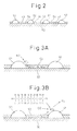
- FIG. 2 schematically shows a surface part of a catalyst carrier which is carried on a substrate of the exhaust purification catalyst 13.
- a catalyst carrier 50 made of alumina on which precious metal catalysts 51 and 52 are carried.
- a basic layer 53 is formed which includes at least one element selected from potassium K, sodium Na, cesium Cs, or another such alkali metal, barium Ba, calcium Ca, or another such alkali earth metal, a lanthanoid or another such rare earth and silver Ag, copper Cu, iron Fe, iridium Ir, or another metal able to donate electrons to NO x .
- the exhaust gas flows along the top of the catalyst carrier 50, so the precious metal catalysts 51 and 52 can be said to be carried on the exhaust gas flow surface of the exhaust purification catalyst 13. Further, the surface of the basic layer 53 exhibits basicity, so the surface of the basic layer 53 is called the basic exhaust gas flow surface part 54.
- the precious metal catalyst 51 is comprised of platinum Pt
- the precious metal catalyst 52 is comprised of rhodium Rh. That is, the precious metal catalysts 51 and 52 which are carried on the catalyst carrier 50 are comprised of platinum Pt and rhodium Rh.
- palladium Pd may be further carried or, instead of rhodium Rh, palladium Pd may be carried. That is, the precious metal catalysts 51 and 52 which are carried on the catalyst carrier 50 are comprised of platinum Pt and at least one of rhodium Rh and palladium Pd.
- the basic layer 53 absorbs the NO x when the air-fuel ratio of the exhaust gas is lean and releases the absorbed NO x when the oxygen concentration in the exhaust gas falls, i.e., performs an NO x absorption and release action. Note that, the basic layer 53 sometimes adsorbs NO x when the air-fuel ratio of the exhaust gas is lean.
- the basic layer 53 stores the NO x when the air-fuel ratio of the exhaust gas is lean and releases the stored NO x when the oxygen concentration in the exhaust gas falls, i.e., performs an NO x storage and release action.
- the air-fuel ratio of the exhaust gas flowing into the exhaust purification catalyst 13 is made the stoichiometric air-fuel ratio or rich, so the oxygen concentration in the exhaust gas falls, so the reaction proceeds in the opposite direction (NO 3 - ⁇ NO 2 ) and therefore the nitrates stored in the basic layer 53 gradually becomes nitrate ions NO 3 - and, as shown in FIG. 3B , are released from the basic layer 53 in the form of NO 2 . Next, the released NO 2 is reduced by the hydrocarbons HC and CO contained in the exhaust gas.
- FIG. 4 shows the control for release of NO x from this basic layer 53. That is, in this embodiment according to the present invention, as shown in FIG. 4 , when the stored NO x amount ⁇ NOX stored in the basic layer 53 exceeds a predetermined allowable amount MAX, the air-fuel ratio (A/F) in of the exhaust gas flowing into the exhaust purification catalyst 13 is temporarily made rich. If the air-fuel ratio (A/F) in of the exhaust gas is made rich, the NO x which was stored in the basic layer 53 when the air-fuel ratio (A/F) in of the exhaust gas was lean is released from the basic layer 53 all at once and reduced. Due to this, the NO x is removed.
- the stored NO x amount ⁇ NOX is, for example, calculated from the amount of NO x which is exhausted from the engine.
- the NO x amount NOXA which is exhausted from the engine per unit time is stored as a function of the engine load L and the engine speed N in the form of a map such as shown in FIG. 5 in advance in the ROM 32. From this exhausted NO x amount NOXA, the stored NO x amount ⁇ NOX is calculated.
- the period by which the air-fuel ratio (A/F) in of the exhaust gas is made rich is usually 1. minute or more.
- the exhaust purification catalyst 13 functions as an NO x storage catalyst which stores the NO x when the air-fuel ratio of the exhaust gas is lean and releases the stored NO x when the oxygen concentration in the exhaust gas falls.
- additional fuel W is injected in addition to the combustion use fuel M into the combustion chambers 2 from the fuel injectors 3 so as to make the air-fuel ratio (A/F) in of the exhaust gas flowing into the exhaust purification catalyst 13 rich .
- the abscissa of FIG. 6 shows the crank angle.
- This additional fuel M is injected at a timing where it is burned, but does not appear as engine output, that is, slightly before ATDC90° after compression top dead center.
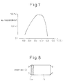
- FIG. 7 shows the NO x purification rate when making the exhaust purification catalyst 13 function as an NO x storage catalyst in this way.
- the abscissa of the FIG. 7 shows the catalyst temperature TC of the exhaust purification catalyst 13.
- the catalyst temperature TC is 300°C to 400°C
- an extremely high NO x purification rate is obtained, but when the catalyst temperature TC becomes a 400°C or higher high temperature, the NO x purification rate falls.
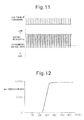
- exhaust gas contains SO x , that is, SO 2 . If this SO 2 flows into the exhaust purification catalyst 13, this SO 2 is oxidized on the platinum Pt 51 and becomes SO 3 . Next, this SO 3 is stored in the basic layer 53 and bonds with the barium carbonate BaCO 3 while diffusing inside the basic layer 53 in the form of sulfate ions SO 4 2- to thereby produce the stable sulfate BcaSO 4 .
- This sulfate BaSO 4 is produced in the region where the exhaust gas first contacts the exhaust purification catalyst 13, that is, in FIG. 8 , the upstream side end region of the exhaust purification catalyst 13 shown by 13a,
- the basic layer 53 has a strong basicity, so the sulfate BaSO 4 is stable and hard to break down. If just making the air-fuel ratio of the exhaust gas rich, the sulfate BaSO 4 will remain as it is without being broken down. Therefore, inside the basic layer 53, along with the elapse of time, the sulfate BaSO 4 will increase, therefore, along with the elapse of time, the amount of NO x which the basic layer 53 can store will fall. As a result, as shown by the solid line in FIG. 9 , the greater the SO x amount ⁇ SOX which is stored in the basic layer 53, that is, the greater the sulfur poisoning of the exhaust purification catalyst 13, the more the NO x purification rate of the exhaust purification catalyst 13 will fall.
- the basicity of the basic layer 53 will weaken and, as a result, the oxidizing function on the hydrocarbons HC by the precious metal, for example, platinum Pt 51, will be enhanced. That is, in this embodiment according to the present invention, the action of oxidizing the hydrocarbons HC at the upstream side end region 13a of the exhaust purification catalyst 13 is enhanced. As a result, for example, when injecting hydrocarbons from the hydrocarbon feed valve 15, the injected hydrocarbons can be reformed at the upstream side end region 13a of the exhaust purification catalyst 13.
- FIG. 10 illustrates the reforming action performed at the upstream side end region 13a of the exhaust purification catalyst 13 at this time.
- the hydrocarbons HC injected from the hydrocarbon feed valve 15 become radical hydrocarbons HC with a small carbon number due to the platinum Pt 51.
- the new method discovered by the inventors could be used to remove the NO x .
- this new NO x purification method will be explained. Note that, the new NO x purification method explained below will be referred to as the first NO x purification method, while the NO x purification method using the NO x storage and release action already explained with reference to FIG. 3 to FIG. 7 will be referred to as the second NO x purification method.
- FIG. 11 shows the timing of feeding hydrocarbons from the hydrocarbon feed valve 15 and the changes in the air-fuel ratio (A/F)in of the exhaust gas flowing into the exhaust purification catalyst 13.
- the changes in the air-fuel ratio (A/F) in depend on the change in concentration of the hydrocarbons in the exhaust gas which flows into the exhaust purification catalyst 13, so it can be said that the change in the air-fuel ratio (A/F)in shown in FIG. 11 expresses the change in concentration of the hydrocarbons.
- the hydrocarbon concentration becomes higher the air-fuel ratio (A/F)in becomes smaller, so, in FIG. 11 , the more to the rich side the air-fuel ratio (A/F) in becomes, the higher the hydrocarbon concentration.
- FIG. 12 shows the NO x purification rate by the exhaust purification catalyst 13 with respect to the catalyst temperatures of the exhaust purification catalyst 13 when periodically making the concentration of hydrocarbons flowing into the exhaust purification catalyst 13 change so as to, as shown in FIG. 11 , make the air-fuel ratio (A/F)in of the exhaust gas flowing to the exhaust purification catalyst 13 change.
- the inventors engaged in research relating to NO x purification for a long time. In the process of research, they learned that if making the concentration of hydrocarbons flowing into the exhaust purification catalyst 13 vibrate by within a predetermined range of amplitude and within a predetermined range of period, as shown in FIG. 11 , an extremely high NO x purification rate is obtained even in a 400°C or higher high temperature region as shown in FIG. 12 .
- FIGS. 13A and 13B schematically show the surface part of the catalyst carrier 50 of the exhaust purification catalyst 13.
- FIGS. 13A and 13B show the reaction which is presumed to occur when the concentration of hydrocarbons flowing into the exhaust purification catalyst 13 is made to vibrate by within a predetermined range of amplitude and within a predetermined range of period.
- FIG. 13A shows when the concentration of hydrocarbons flowing into the exhaust purification catalyst 13 is low
- FIG. 13B shows when hydrocarbons are fed from the hydrocarbon feed valve 15 and the concentration of hydrocarbons flowing into the exhaust purification catalyst 13 becomes high.
- the air-fuel ratio of the exhaust gas which flows into the exhaust purification catalyst 13 is maintained lean except for an instant, so the exhaust gas which flows into the exhaust purification catalyst 13 normally becomes a state of oxygen excess. Therefore, the NO which is contained in the exhaust gas, as shown it FIG. 13A , is oxidized on the platinum 51 and becomes NO 2 . Next, this NO 2 is supplied with electrons from the platinum 51 and becomes NO 2 - . Therefore, a large amount of NO 2 - is produced on the platinum 51. This NO 2 - is strong in activity. Above, this NO 2 - is called the active NO 2 * .
- the hydrocarbons are fed from the hydrocarbon feed valve 15, as shown in FIG. 10 , the hydrocarbons are reformed and become radicalized inside of the exhaust purification catalyst 13. As a result, as shown in FIG. 13B , the hydrocarbon concentration around the active NO 2 * becomes higher.
- the active NO 2 * is produced, if the state of a high oxygen active NO 2 * is produced, if the state ot a high oxygen concentration around the active NO 2 * continues for a predetermined time or more, the active NO 2 * is oxidized and is absorbed in the basic layer 53 in the form of nitrate ions NO 3 - .
- the active NO 2 * reacts on the platinum 51 with the radical hydrocarbons HC whereby a reducing intermediate is produced.
- This reducing intermediate is adhered or adsorbed on the surface of the basic layer 53.
- the first produced reducing intermediate is considered to be a nitro compound R-NO 2 . If this nitro compound R-NO 2 is produced, the result becomes a nitrile compound R-CN, but this nitrile compound R-CN can only survive for an instant in this state, so immediately becomes an isocyanate compound R-NCO. However, in this case, what is hydrolyzed is considered to be part of the isocyanate compound R-NCO. Therefore, as shown in FIG. 13B , the majority of the reducing intermediate which is held or adsorbed on the surface of the basic layer 53 is believed to be the isocyanate compound R-NCO and amine compound R-NH 2 .
- the active NO 2 * is absorbed in the basic layer 53 in the form of nitrates without producing a reducing intermediate. To avoid this, it is necessary to make the concentration of hydrocarbons flowing into the exhaust purification catalyst 13 vibrate by within a predetermined range of period.
- the precious metal catalysts 51 and 52 are carried on the exhaust gas flow surface of the exhaust purification catalyst 13.
- the basin exhaust gas flow surface part 54 is formed around the precious metal catalysts 51 and 52.
- NO x is reduced by the reducing action of the reducing intermediate R-NCO or R-NH 2 held on basic exhaust gas flow surface part 54, and the vibration period of the hydrocarbon concentration is made the vibration period required for continuation of the production of the reducing intermediate R-NCO or R-NH 2 .
- the injection interval is made 3 seconds.
- the second NO x purification method when the second NO x purification method is used, as shown in FIG. 7 , when the catalyst temperature TC becomes 400°C or more, the NO x purification rate falls because if the catalyst temperature TC becomes 400°C or more, the nitrates break down by heat and are released in the form of NO 2 from the exhaust purification catalyst 13. That is, so long as storing NO x in the form of nitrates, when the catalyst temperature its high, it is difficult to obtain a high NO x purification rate.
- the first NO x purification method shown from FIG. 10 to FIGS. 13A and 13B as will be understood from FIGS. 13A and 13B , nitrates are not formed or even if formed are extremely fine in amount, consequently, as shown in FIG. 12 , even when the catalyst temperature TC is high, a high NO x purification rate is obtained.
- the first NO x purification method which is shown from FIG. 10 to FIGS. 13A and 12B can be said to be a new NO x purification method designed to remove NO x without forming almost any nitrates in the case of using an exhaust purification catalyst which carries a precious metal catalyst and forms a basic layer which can absorb NO x .
- the nitrates which are detected from the basic layer 53 become much smaller in amount compared with the case where using the second NO x purification method.
- FIG. 14 shows enlarged the change in the air-fuel ratio (A/F)in shown in FIG. 11 .
- the change in the air-fuel ratio (A/F)in of the exhaust gas flowing into this exhaust purification catalyst 13 simultaneously shows the change in concentration of the hydrocarbons which flow into the exhaust purification catalyst 13.
- ⁇ H shows the amplitude of the change in concentration of hydrocarbons HC which flow into the exhaust purification catalyst 13
- ⁇ T shows the vibration period of the concentration of the hydrocarbons which flow into the exhaust purification catalyst 13.
- (A/F)b shows the base air-fuel ratio which shows the air-fuel ratio of the combustion gas for generating the engine output.
- this base air-fuel ratio (A/F)b shows the air-fuel ratio of the exhaust gas which flows into the exhaust purification catalyst 13 when stopping the feed of hydrocarbons.
- X shows the upper limit of the air-fuel ratio (A/F)in which is used for producing the reducing intermediate without the produced active NO 2 * being stored in the form of nitrates inside the basic layer 53. To make the active NO 2 * and the reformed hydrocarbons react and produce the reducing intermediate, it is necessary to make the air-fuel ratio (A/F)in lower than the upper limit X of this air-fuel ratio.
- X shows the lower limit of the concentration of hydrocarbons required for making the active NO 2 * and reformed hydrocarbon react to produce a reducing intermediate.
- the concentration of hydrocarbons has to be made higher than this lower limit X.
- whether the reducing intermediate is produced is determined by the ratio of the oxygen concentration and hydrocarbon concentration around the active NO 2 * , that is, the air-fuel ratio (A/F)in.
- the upper limit X of the air-fuel ratio required for producing the reducing intermediate will below be called the demanded minimum air-fuel ratio.
- the demanded minimum air-fuel ratio X is rich, therefore, in this case, to form the reducing intermediate, the air-fuel ratio (A/F)in is instantaneously made the demanded minimum air-fuel ratio X or less, that is, rich.
- the demanded minimum air-fuel ratio X is lean. In this case, the air-fuel ratio (A/F)in is maintained lean while periodically reducing the air-fuel ratio (A/F)in so as to form the reducing intermediate.
- the exhaust purification catalyst 13 for example, becomes stronger in oxidizing strength if increasing the carried amount of the precious metal 51 and becomes stronger in oxidizing strength if strengthening the acidity. Therefore, the oxidizing strength of the exhaust purification catalysts 13 changes due to the carried amount of the precious metal 51 or the strength of the acidity.
- the demanded minimum air-fuel ratio X has to be reduced the stronger the oxidizing strength of the exhaust purification catalyst 13. In this way, the demanded minimum air-fuel ratio X becomes lean or rich due to the oxidizing strength of the exhaust purification catalyst 13.
- the amplitude of the change in concentration of hydrocarbons flowing into the exhaust purification catalyst 13 and the vibration period of the concentration of hydrocarbons flowing into the exhaust purification catalyst 13 will be explained.
- FIG. 17 shows the relationship between the oxygen concentration in the exhaust gas before the hydrocarbons are fed and the amplitude ⁇ H of the hydrocarbon concentration when the same NO x purification rate is obtained. From FIG. 17 , it is learned that to obtain the same NO x purification rate, the higher the oxygen concentration in the exhaust gas before the hydrocarbons are fed, the greater the amplitude ⁇ H of the hydrocarbon concentration has to be made. That is, to obtain the same NO x purification rate, the higher the base air-fuel ratio (A/F)b, the greater the amplitude ⁇ T of the hydrocarbon concentration has to be made. In other words, to remove the NO x well, the lower the base air-fuel ratio (A/F)b, the more the amplitude ⁇ T of the hydrocarbon concentration can be reduced.
- the base air-fuel ratio (A/F)b becomes the lowest at the time of an acceleration operation. At this time, if the amplitude ⁇ H of the hydrocarbon concentration is about 200 ppm, it is possible to remove the NO x well.
- the base air-fuel ratio (A/F)b is normally larger than the time of acceleration operation. Therefore, as shown in FIG. 18 , if the amplitude ⁇ H of the hydrocarbon concentration is 200 ppm or more, an excellent NO x purification rate can be obtained.
- the base air-fuel ratio (A/F)b is the highest, if making the amplitude ⁇ H of the hydrocarbon concentration 10000 ppm or so, an excellent NO x purification rate is obtained. Further, if the amplitude ⁇ H of the hydrocarbon concentration is over 10000 ppm, there is the danger that the air-fuel ratio (A/F)in will become rich. Therefore, there is the danger that the new NO x purification method can no longer be performed. Therefore, in the present invention, when performing the first NO x purification method, the predetermined range of the amplitude of the hydrocarbon concentration is made 200 ppm to 10000 ppm.
- the vibration period ⁇ T of the hydrocarbon concentration becomes longer, the oxygen concentration around the active NO 2 * becomes higher in the time after the hydrocarbons are fed to when the hydrocarbons are next fed.
- the vibration period ⁇ T of the hydrocarbon concentration becomes longer than about 5 seconds, the active NO 2 * starts to be absorbed in the form of nitrates inside the basic layer 53. Therefore, as shown in FIG. 19 , if the vibration period ⁇ T of the hydrocarbon concentration becomes long than about 5 seconds, the NO x purification rate will fall. Therefore, the vibration period ⁇ T of the hydrocarbon concentration has to be made 5 seconds or less.
- the vibration period ⁇ T of the hydrocarbon concentration becomes about 0.3 second or less, the fed hydrocarbons start to build up on the exhaust gas flow surface of the exhaust purification catalyst 13. Therefore, as shown in FIG. 19 , if the vibration period ⁇ T of the hydrocarbon concentration becomes substantially 0.3 second or less, the NO x purification rate falls, Therefore, in the present invention, when performing the first NO x purification method, the vibration period of the hydrocarbon concentration is made from 0.3 second to 5 seconds.
- the first NO x purification method to remove the NO x
- the second NO x purification method when the NO x concentration in the exhaust gas is low, the time until the stored NO x amount ⁇ NOX reaches the allowable value MAX becomes longer, so the period by which the air-fuel ratio (A/F)in of the exhaust gas is made rich merely becomes longer.
- the NO x purification efficiency does not particularly become poor. Therefore, when the NO x concentration in the exhaust gas is low, it can be said to be preferable to use the second NO x purification method rather than the first NO x purification method.
- the broken line of FIG. 9 shows the change in the NO x purification rate when the first NO x purification method is used.
- the NO x purification rate by the first NO x purification method first increases along with an increase in the sulfur poisoning, then gradually declines. That is, if the sulfur poisoning increases, the oxidation function with respect to the hydrocarbons HC becomes stronger, so the NO x purification rate gradually increases. However, if the sulfur poisoning further increases, the basicity of the basic layer 53 becomes weaker, so the holding force with regard to the reducing intermediate R-NCO or R-NH 2 becomes weaker and therefore the NO x purification rate gradually decreases.
- the hydrocarbons HC and the reducing intermediate R-NCO or R-NH 2 will disappear from the surface of the basic layer 53.
- the nitrate ions NO 3 - formed on the platinum Pt 51 will, as shown in FIG. 3A , diffuse in the basic layer 53 and become nitrates. That is, at this time, the NO x in the exhaust gas is stored in the form of nitrates in the basic layer 53. Therefore, in this case, the NO x purification method becomes not the first NO x purification method, but the second NO x purification method.
- the first NO x purification method and the second NO x purification method are selectively used in accordance with the sulfur poisoning of the exhaust purification catalyst 13.
- the exhaust purification catalyst 13 has the property of storing the NO x which is contained in exhaust gas when the air-fuel ratio of the exhaust gas flowing into the exhaust purification catalyst 13 is lean and releasing the stored NO x when the air-fuel ratio of the inflowing exhaust gas becomes rich and has the property of reducing the NO x which is contained in exhaust gas if making the concentration of hydrocarbons flowing into the exhaust purification catalyst 13 vibrate within a predetermined range of amplitude and within a predetermined range of period when the sulfur poisoning of the exhaust purification catalyst 13 increases and, at the time of engine operation, a first NO x purification method which makes the concentration of hydrocarbons flowing into the exhaust purification catalyst vibrate by within a predetermined range of amplitude and within a predetermined range of period to thereby remove the NO x which is contained in exhaust gas and a second NO x purification method which switches the air-fuel ratio of the exhaust gas flowing into the exhaust purification catalyst from lean to rich by
- the first NO x purification method when use of the first NO x purification method would result in a higher NO x purification efficiency than use of the second NO x purification method, the first NO x purification method is used, while when use of the second NO x purification method would result in a higher NO x purification efficiency than use of the first NO x purification method, the second NO x purification method is used.
- the sulfur poisoning SX1 for when the NO x purification rate when using the first NO x purification method and the NO x purification rate when using the second NO x purification method become equal is found in advance by experiment.
- This sulfur poisoning SX1 is used as a reference amount for switching of the NO x purification method. That is, when the sulfur poisoning of the exhaust purification catalyst 13 is less than a predetermined reference amount SX1, the second NO x purification method is used, while when the sulfur poisoning of the exhaust purification catalyst 13 exceeds the predetermined reference amount SX1, the first NO x purification method is used.
- the sulfur poisoning exceeds the reference amount SX1 and the first NO x purification method is used, as shown by the broken line in FIG. 9 , first, the NO x purification rate increases as the sulfur poisoning increases. When the sulfur poisoning further increases, the NO x purification rate falls. When the NO x purification rate falls in this way, in so far as the sulfur poisoning is not reversed, it will no longer be possible to raise the NO x purification rate. Therefore, in this embodiment according to the present invention, if the sulfur poisoning of the exhaust purification catalyst 13 reaches a predetermined limit amount SX2 larger than the reference amount SX1, sulfur poisoning recovery processing is performed.
- the temperature of the exhaust purification catalyst 13 is made to rise to a 600°C or higher SO x release temperature and, in that state, the air-fuel ratio of the exhaust gas flowing into the exhaust purification catalyst 13 is made rich, it is possible to make the exhaust purification catalyst 13 release the SO x . Therefore, in this embodiment according to the present invention, the temperature of the exhaust purification catalyst 13 is made to rise to a 600°C or higher SO x release temperature and, in that state, the air-fuel ratio of the exhaust gas flowing into the exhaust purification catalyst 13 is made rich so as to perform SO x poisoning recovery processing.
- the sulfur poisoning of the exhaust purification catalyst 13 can be represented by the amount of SO x stored in the exhaust purification catalyst 13.
- the SO x amount which is stored in the exhaust purification catalyst 13 can be found by cumulatively adding the amounts of SO x which are exhausted from the engine. Therefore, in this embodiment according to the present invention, the exhausted SO x amount SOXA exhausted from the engine per unit time is stored as a function of the engine load L and the engine speed N in the form of a map such as shown in FIG. 20 in advance in the ROM 32.
- the stored SO x amount ⁇ SOX representing the sulfur poisoning is calculated from this exhausted SO x amount SOXA.
- FIG. 21 shows one example of an exhaust purification method according to the present invention. Note that, FIG. 21 shows the change of the air-fuel ratio (A/F)in of the exhaust gas flowing into the exhaust purification catalyst 13, the change of the stored NO x amount ⁇ NOX stored in the exhaust purification catalyst 13, and the change of the stored SO x amount ⁇ SOX stored in the exhaust purification catalyst 13.
- A/F air-fuel ratio
- the second NO x purification method is used for the NO x purification action. That is, at this time, each time the stored NO x amount ⁇ NOX of the exhaust purification catalyst 13 exceeds the allowable value MAX, the air-fuel ratio (A/F)in of the exhaust gas flowing into the exhaust purification catalyst 13 is made rich.
- the NO x purification method is switched from the second NO x purification method to the first NO x purification method. Therefore, at this time, hydrocarbons are injected from the hydrocarbon feed valve 15 by the predetermined period.
- SO x poisoning recovery processing is performed. That is, the temperature of the exhaust purification catalyst 13 is made to rise to a 600°C or higher SO x release temperature and, in that state, the air-fuel ratio (A/F)in of the exhaust gas flowing into the exhaust purification catalyst 13 is made rich for a short interval.
- A/F air-fuel ratio
- the air-fuel ratio (A/F)in of the exhaust gas a certain rich degree or higher rich level, it is possible to reduce the stored NO x which remains at the exhaust purification catalyst 13 and therefore possible to prevent NO x from being exhausted into the atmosphere. Therefore, in this embodiment according to the present invention, as shown in FIG. 21 , when switched from the second NO x purification method to first NO x purification method, the air-fuel ratio of the exhaust gas flowing into the exhaust purification catalyst 13 is temporarily made a certain rich degree or higher rich level to release and reduce the NO x which is stored in the exhaust purification catalyst 13.
- FIG. 22 shows a processing routine for exhaust purification for working the embodiment shown in FIG. 21 .
- This routine is executed by interruption every predetermined time.
- the SO x amount SOXA exhausted per unit time is calculated from the map shown in FIG. 20 .
- this exhausted SO x amount SOXA is added to ⁇ SOX to calculate the stored SO x amount ⁇ SOX stored in the exhaust purification catalyst 13.
- the routine proceeds to step 63 where it is judged if the stored SO x amount ⁇ SOX exceeds the reference amount SX1.
- the routine proceeds to step 64.
- the NO x amount NOXA exhausted per unit time is calculated from the map shown in FIG. 5 .
- this exhausted NO x amount NOXA is added to ⁇ NOX so as to calculate the stored NO x amount ⁇ NOX which is stored in the exhaust purification catalyst 13.
- the routine proceeds to step 67 where the air-fuel ratio (A/F)in of the exhaust gas flowing into the exhaust purification catalyst 13 is made temporarily a certain rich degree or higher rich level.
- ⁇ NOX is cleared.
- step 69 it is judged if the NO x purification method has now been switched from the second NO x purification method to the first NO x purification method.
- the routine proceeds to step 67 where the air-fuel ratio (A/F) in of the exhaust gas flowing into the exhaust purification catalyst. 13 is made temporarily a certain rich degree or higher rich level.
- the routine proceeds to step 70 where hydrocarbons are injected from the hydrocarbon feed valve 15 by the predetermined period.
- step 71 SO x poisoning recovery processing is performed. That is, the temperature of the exhaust purification catalyst 13 is made to rise to a 600°C or higher SO x release temperature and, in that state, the air-fuel ratio or the exhaust gas flowing into the exhaust purification catalyst 13 is made rich for a short interval.
- step 72 it is judged if the SO x poisoning recovery processing is completed.
- the routine proceeds to step 73 where ⁇ SOX is cleared.
- the exhaust purification catalyst 13 has an oxygen storage ability, for example, when it contains cesium Ce, if sulfur poisoning progresses, the ceria CeO 2 is changed to the sulfate CeSO 4 . Therefore, in this case, as shown in FIG. 23A , the greater the sulfur poisoning, that is, the greater the stored SO x amount ⁇ SOX, the more the oxygen storage amount of the exhaust purification catalyst 13 is decreased.
- the first NO x purification method is used to remove the NO x , if hydrocarbons are fed from the hydrocarbon feed valve 15, part of the hydrocarbons will be oxidized by the oxygen which is stored in the exhaust purification catalyst 13. In ether words, part of the fed hydrocarbons will be used for consuming the stored oxygen, On the other hand, to remove the NO x , a certain amount of hydrocarbons is required. Therefore, as shown in FIG. 23B , the smaller the oxygen storage amount, that is, the greater the sulfur poisoning, the more the amount of feed of hydrocarbons can be decreased.
- the amount of oxygen which is stored in the exhaust purification catalyst 13 is reduced, when the first NO x purification method is being used, the amount of hydrocarbons which is injected from the hydrocarbon feed valve 15 is made to fall.
- an oxidation catalyst for modifying the hydrocarbons in the engine exhaust passage upstream of the exhaust purification catalyst 13, an oxidation catalyst for modifying the hydrocarbons can be arranged.
Abstract
Description
- The present invention relates to an exhaust purification system of an internal combustion engine.
- Known in the art is an internal combustion engine which arranges, in an engine exhaust passage, an NOx storage catalyst which stores NOx which is contained in exhaust gas when the air-fuel ratio of the inflowing exhaust gas is lean and which releases the stored NOx when the air-fuel ratio of the inflowing exhaust gas becomes rich, which arranges, in the engine exhaust passage upstream of the NOx storage catalyst, an oxidation catalyst which has an adsorption function, and which feeds hydrocarbons into the engine exhaust passage upstream of the oxidation catalyst to make the air-fuel ratio of the exhaust gas flowing into the NOx storage catalyst rich when releasing NOx from the NOx storage catalyst (for example, see Patent Literature 1).
- In this internal combustion engine, the hydrocarbons which are fed when releasing NOx from the NOx storage catalyst are made gaseous hydrocarbons at the oxidation catalyst, and the gaseous hydrocarbons are fed to the NOx storage catalyst. As a result, the NOx which is released from the NOx storage catalyst is reduced well.
-
- Patent Literature 1: Japanese Patent No.
3969450 - In this regard, fuel and lubricants contain sulfur. Therefore, the exhaust gas contains SOx. This SOx is stored together with the in the NOx storage catalyst. In this regard, this SOx is not released from the NOx storage catalyst by just the air-fuel ratio of the exhaust gas being made rich. Therefore, the amount of SOx which is stored in the NOx storage catalyst gradually increases. As a result, the NOx amount which can be stored gradually decreases, so the NOx purification rate gradually decreases.
- However, recently, a new NOx purification method enabling NOx to be removed by a high purification rate when the SOx storage amount increases was discovered by the inventors. Therefore, if using this new NOx purification method when the SOx storage amount increases, it is possible to remove NOx by a high NOx purification rate regardless of the SOx storage amount.
- An object of the present invention is to provide an exhaust purification system of an internal combustion engine which enables a high NOx purification rate to be obtained regardless of the SOx storage amount.
- According to the present invention, there is provided an exhaust purification system of an internal combustion engine wherein an exhaust purification catalyst for reacting NOx contained in exhaust gas and reformed hydrocarbons is arranged is an engine exhaust passage, precious metal catalysts are carried and a basic layer is formed on the exhaust purification catalyst, the exhaust purification catalyst has a property of storing NOx which is contained in exhaust gas when an air-fuel ratio of an exhaust gas flowing into the exhaust purification catalyst is lean and releasing stored NOx when the air-fuel ratio of the inflowing exhaust gas becomes rich and has a property of reducing the NOx which is contained in exhaust gas if making a concentration of hydrocarbons flowing into the exhaust purification catalyst vibrate within a predetermined range of amplitude and within a predetermined range of period when a sulfur poisoning of the exhaust purification catalyst increases, and, at the time of engine operation, a first NOx purification method which makes the concentration of hydrocarbons flowing into the exhaust purification catalyst vibrate by within the predetermined range of amplitude and within the predetermined range of period to thereby remove the NOx which is contained in exhaust gas and a second NOx purification method which switches the air-fuel ratio of the exhaust gas flowing into the exhaust purification catalyst from lean to rich by a period longer than the above predetermined range of period to thereby remove the NOx are selectively used in accordance with the sulfur poisoning of the exhaust purification catalyst.
- By selectively using the first NOx purification method and the second Purify method, it is possible to obtain a high NOx purification rate regardless of the sulfur poisoning of the exhaust purification catalyst.
-
-
FIG. 1 is an overall view of a compression ignition type internal combustion engine. -
FIG. 2 is a view schematically showing a surface part of a catalyst carrier. -
FIGS. 3A and 3B are views for explaining an oxidation reduction reaction in an exhaust purification catalyst. -
FIG. 4 is a view showing a change in the air-fuel ratio of exhaust gas flowing to an exhaust purification catalyst etc. -
FIG. 5 is a view showing a map of an exhausted NOx amount NOXA. -
FIG. 6 is a view showing a fuel injection timing. -
FIG. 7 is a view showing an NOx purification rate. -
FIG. 8 is a view for explaining SOx poisoning. -
FIG. 9 is a view of an NOx purification rate. -
FIG. 10 is a view for explaining an oxidation reaction in ain exhaust purification catalyst. -
FIG. 11 is a view showing a change in an air-fuel ratio of exhaust gas flowing to an exhaust purification catalyst. -
FIG. 12 is a view showing an NOx purification rate. -
FIGS. 13A and 13B are views for explaining an oxidation reduction reaction in an exhaust purification catalyst. -
FIG. 14 is a time chart showing a change in an air-fuel ratio of exhaust gas flowing to an exhaust purification catalyst . -
FIG. 15 is a time chart showing a change in an air-fuel ratio of exhaust gas flowing to an exhaust purification catalyst. -
FIG. 16 is a view showing a relationship between an oxidizing strength of an exhaust purification catalyst and a demanded minimum air-fuel ratio X. -
FIG. 17 is a view showing a relationship between an oxygen concentration in exhaust gas and an amplitude ΔH of a hydrocarbon concentration giving the same NOx purification rate. -
FIG. 18 is a view showing a relationship between an amplitude ΔH of a hydrocarbon concentration and an NOx purification rate. -
FIG. 19 is a view showing a relationship of a vibration period ΔT of a hydrocarbon concentration and an NOx purification rate. -
FIG. 20 is a view showing a map of an exhausted SOx amount SOXA. -
FIG. 21 is a time chart showing a change in an air-fuel ratio (A/F) in of exhaust gas etc. when an exhaust purification method according to the present invention is being performed. -
FIG. 22 is a flow chart for exhaust purification processing. -
FIGS. 23A and 23B are views for explaining an amount of feed of hydrocarbons at the time of SOx poisoning. -
FIG. 1 is an overall view of a compression ignition type internal combustion engine. - Referring to
FIG. 1, 1 indicates an engine body, 2 a combustion chamber- of each cylinder, 3 an electronically controlled fuel injector for injecting fuel into eachcombustion chamber intake manifold 4 is connected through anintake duct 6 to an outlet of acompressor 7a of an exhaust turbocharger 7, while an inlet of thecompressor 7a is connected through an intake air amount detector 8 to anair cleaner 9. Inside theintake duct 6, athrottle valve 10 driven by a step motor is arranged. Furthermore, around theintake duct 6, acooling device 11 is arranged for cooling the intake air which flows through the inside of theintake duct 6. In the embodiment shown inFIG. 1 , the engine cooling water is guided to the inside of thecooling device 11 where the engine cooling water is used to cool the intake air. - On the other hand, as shown in
FIG. 1 , the exhaust manifold 5 is connected to an inlet of an exhaust turbine 7b of an exhaust turbocharger. The outlet of the exhaust turbine 7b is connected through anexhaust pipe 12 to an inlet of theexhaust purification catalyst 13, while the outlet of theexhaust purification catalyst 13 is connected to aparticulate filter 14 for trapping particulate which is contained in the exhaust gas. Inside theexhaust pipe 12 upstream of theexhaust purification catalyst 13, ahydrocarbon feed valve 15 is arranged for feeding hydrocarbons comprised of diesel oil or other fuel used as fuel for a compression ignition type internal combustion engine. In the embodiment shown inFIG. 1 , diesel oil is used as the hydrocarbons which are fed from thehydrocarbon feed valve 15. Note that, the present invention can also be applied to a spark ignition type internal combustion engine in which fuel is burned under a lean air-fuel ratio. In this case, from thehydrocarbon feed valve 15, hydrocarbons comprised of gasoline or other fuel used as fuel of a spark ignition type internal combustion engine are fed. - On the other hand, the exhaust manifold 5 and the
intake manifold 4 are connected with each other through an exhaust gas recirculation (hereinafter referred, to as an "EGR")passage 16. Inside theEGR passage 16, an electronically controlledEGR control valve 17 is arranged. Further, around theEGR passage 16, acooling device 18 is arranged for cooling BGE gas flowing through the inside of theEGR passage 16. In the embodiment shown inFIG. 1 , the engine cooling water is guided to the inside of thecooling device 18 where the engine cooling water is used to cool the EGR gas. On the other hand, eachfuel injector 3 is connected through afuel feed tube 19 to acommon rail 20. Thiscommon rail 20 is connected through an electronically controlled variabledischarge fuel pump 21 to afuel tank 22. The fuel which is stored inside of thefuel tank 22 is fed by thefuel pump 21 to the inside of thecommon rail 20. The fuel which is fed to the inside of thecommon rail 20 is fed through eachfuel feed tube 19 to thefuel injector 3. - An
electronic control unit 30 is comprised of a digital computer provided with a ROM (read only memory) 32, a RAM (random access memory) 33, a CPU (microprocessor) 34, aninput port 35, and anoutput port 36, which are connected with each other by abidirectional bus 31. At theexhaust purification catalyst 13, atemperature sensor 23 for detecting the temperature of theexhaust purification catalyst 13 is attached. The output signals of thistemperature sensor 23 and intake air amount detector 8 are input through respectively correspondingAD converters 37 to theinput port 35. Further, theaccelerator pedal 40 has aload sensor 41 connected to it which generates an output voltage proportional to the amount of depression L of theaccelerator pedal 40. The output voltage of theload sensor 41 is input through acorresponding AD converter 37 to theinput port 35. Furthermore, at theinput port 35, acrank angle sensor 42 is connected which generates an output pulse every time a crankshaft rotates by, for example, 15°. On the other hand, theoutput port 36 is connected throughcorresponding drive circuits 38 to eachfuel injector 3, a step motor for driving thethrottle valve 10,hydrocarbon feed valve 15,EGR control valve 17, andfuel pump 21. -
FIG. 2 schematically shows a surface part of a catalyst carrier which is carried on a substrate of theexhaust purification catalyst 13. At thisexhaust purification catalyst 13, as shown inFIG. 2 , for example, there is provided acatalyst carrier 50 made of alumina on whichprecious metal catalysts catalyst carrier 50, abasic layer 53 is formed which includes at least one element selected from potassium K, sodium Na, cesium Cs, or another such alkali metal, barium Ba, calcium Ca, or another such alkali earth metal, a lanthanoid or another such rare earth and silver Ag, copper Cu, iron Fe, iridium Ir, or another metal able to donate electrons to NOx. The exhaust gas flows along the top of thecatalyst carrier 50, so theprecious metal catalysts exhaust purification catalyst 13. Further, the surface of thebasic layer 53 exhibits basicity, so the surface of thebasic layer 53 is called the basic exhaust gasflow surface part 54. - In
FIG. 2 , theprecious metal catalyst 51 is comprised of platinum Pt, while theprecious metal catalyst 52 is comprised of rhodium Rh. That is, theprecious metal catalysts catalyst carrier 50 are comprised of platinum Pt and rhodium Rh. Note that, on thecatalyst carrier 50 of theexhaust purification catalyst 13, in addition to platinum Pt and rhodium Rh, palladium Pd may be further carried or, instead of rhodium Rh, palladium Pd may be carried. That is, theprecious metal catalysts catalyst carrier 50 are comprised of platinum Pt and at least one of rhodium Rh and palladium Pd. - Now, if the ratio of the air and fuel (hydrocarbons) which are fed into the engine intake passage,
combustion chambers 2, and exhaust passage upstream of theexhaust purification catalyst 13 is called the air-fuel ratio of the exhaust, gas, thebasic layer 53 absorbs the NOx when the air-fuel ratio of the exhaust gas is lean and releases the absorbed NOx when the oxygen concentration in the exhaust gas falls, i.e., performs an NOx absorption and release action. Note that, thebasic layer 53 sometimes adsorbs NOx when the air-fuel ratio of the exhaust gas is lean. Therefore, if using the term of storage as a term including both absorption and adsorption, thebasic layer 53 stores the NOx when the air-fuel ratio of the exhaust gas is lean and releases the stored NOx when the oxygen concentration in the exhaust gas falls, i.e., performs an NOx storage and release action. - That is, explaining this taking as an example the case of using barium Ba as the ingredient forming the
basic layer 53, when the air-fuel ratio of the exhaust gas is lean, that is, when the oxygen concentration in the exhaust gas is high, the NO which is contained in the exhaust gas, as shown inFIG. 3A , is oxidized on theplatinum Pt 51 and becomes NO2. Next, this is stored in thebasic layer 53 and bonds with the barium carbonate BaCO3 while diffusing inside thebasic layer 53 in the form of nitrate ions NO3 -. In this way, the NOx is stored in thebasic layer 53. So long as the oxygen concentration in the exhaust gas is high, NO2 is formed on the surface of theplatinum Pt 51. So long as the NOx storage ability of thebasic layer 53 does not become saturated, the NO2 is stored in thebasic layer 53 and nitrate ions NO3 are produced. - As opposed to this, if the air-fuel ratio of the exhaust gas flowing into the
exhaust purification catalyst 13 is made the stoichiometric air-fuel ratio or rich, the oxygen concentration in the exhaust gas falls, so the reaction proceeds in the opposite direction (NO3 -→NO2) and therefore the nitrates stored in thebasic layer 53 gradually becomes nitrate ions NO3 - and, as shown inFIG. 3B , are released from thebasic layer 53 in the form of NO2. Next, the released NO2 is reduced by the hydrocarbons HC and CO contained in the exhaust gas. - In this way, when combustion is performed when the air-fuel ratio of the exhaust gas is lean, that is, under a lean air-fuel ratio, the NOx in the exhaust gas is stored in the
basic layer 53. However, if combustion is continued under a lean air-fuel ratio, eventually, the NOx storage ability of thebasic layer 53 will end up becoming saturated and therefore thebasic layer 53 will no longer be able to store the NOx. Therefore, in this embodiment according to the present invention, before the storage ability of thebasic layer 53 becomes saturated, the air-fuel ratio of the exhaust gas is temporarily made rich and thereby thebasic layer 53 is made to release the NOx. -
FIG. 4 shows the control for release of NOx from thisbasic layer 53. That is, in this embodiment according to the present invention, as shown inFIG. 4 , when the stored NOx amount ΣNOX stored in thebasic layer 53 exceeds a predetermined allowable amount MAX, the air-fuel ratio (A/F) in of the exhaust gas flowing into theexhaust purification catalyst 13 is temporarily made rich. If the air-fuel ratio (A/F) in of the exhaust gas is made rich, the NOx which was stored in thebasic layer 53 when the air-fuel ratio (A/F) in of the exhaust gas was lean is released from thebasic layer 53 all at once and reduced. Due to this, the NOx is removed. - The stored NOx amount ΣNOX is, for example, calculated from the amount of NOx which is exhausted from the engine. In this embodiment according to the present invention, the NOx amount NOXA which is exhausted from the engine per unit time is stored as a function of the engine load L and the engine speed N in the form of a map such as shown in
FIG. 5 in advance in theROM 32. From this exhausted NOx amount NOXA, the stored NOx amount ΣNOX is calculated. The period by which the air-fuel ratio (A/F) in of the exhaust gas is made rich is usually 1. minute or more. - In this NOx purification method, when the air-fuel ratio (A/F) in of the exhaust gas is lean, the NOx which is contained in exhaust gas is stored in the
basic layer 53. Therefore, thebasic layer 53 performs the role as a storage agent for temporarily storing the NOx. That is, in this NOx purification method, theexhaust purification catalyst 13 functions as an NOx storage catalyst which stores the NOx when the air-fuel ratio of the exhaust gas is lean and releases the stored NOx when the oxygen concentration in the exhaust gas falls. - Further, in this NOx purification method, as shown in
FIG. 6 , additional fuel W is injected in addition to the combustion use fuel M into thecombustion chambers 2 from thefuel injectors 3 so as to make the air-fuel ratio (A/F) in of the exhaust gas flowing into theexhaust purification catalyst 13 rich . Note that, the abscissa ofFIG. 6 shows the crank angle. This additional fuel M is injected at a timing where it is burned, but does not appear as engine output, that is, slightly before ATDC90° after compression top dead center. Of course, it is also possible to make the feed amount of hydrocarbons from thehydrocarbon feed valve 15 increase so as to make the air-fuel ratio (A/F) in of the exhaust gas rich. -
FIG. 7 shows the NOx purification rate when making theexhaust purification catalyst 13 function as an NOx storage catalyst in this way. Note that, the abscissa of theFIG. 7 shows the catalyst temperature TC of theexhaust purification catalyst 13. When making theexhaust purification catalyst 13 function as an NOx storage catalyst, as shown inFIG. 7 , when the catalyst temperature TC is 300°C to 400°C, an extremely high NOx purification rate is obtained, but when the catalyst temperature TC becomes a 400°C or higher high temperature, the NOx purification rate falls. - In this regard, exhaust gas contains SOx, that is, SO2. If this SO2 flows into the
exhaust purification catalyst 13, this SO2 is oxidized on theplatinum Pt 51 and becomes SO3. Next, this SO3 is stored in thebasic layer 53 and bonds with the barium carbonate BaCO3 while diffusing inside thebasic layer 53 in the form of sulfate ions SO4 2- to thereby produce the stable sulfate BcaSO4. This sulfate BaSO4 is produced in the region where the exhaust gas first contacts theexhaust purification catalyst 13, that is, inFIG. 8 , the upstream side end region of theexhaust purification catalyst 13 shown by 13a, - In this regard, the
basic layer 53 has a strong basicity, so the sulfate BaSO4 is stable and hard to break down. If just making the air-fuel ratio of the exhaust gas rich, the sulfate BaSO4 will remain as it is without being broken down. Therefore, inside thebasic layer 53, along with the elapse of time, the sulfate BaSO4 will increase, therefore, along with the elapse of time, the amount of NOx which thebasic layer 53 can store will fall. As a result, as shown by the solid line inFIG. 9 , the greater the SOx amount ΣSOX which is stored in thebasic layer 53, that is, the greater the sulfur poisoning of theexhaust purification catalyst 13, the more the NOx purification rate of theexhaust purification catalyst 13 will fall. - In this regard, if are formed in the
basic layer 53, the basicity of thebasic layer 53 will weaken and, as a result, the oxidizing function on the hydrocarbons HC by the precious metal, for example,platinum Pt 51, will be enhanced. That is, in this embodiment according to the present invention, the action of oxidizing the hydrocarbons HC at the upstreamside end region 13a of theexhaust purification catalyst 13 is enhanced. As a result, for example, when injecting hydrocarbons from thehydrocarbon feed valve 15, the injected hydrocarbons can be reformed at the upstreamside end region 13a of theexhaust purification catalyst 13. -
FIG. 10 illustrates the reforming action performed at the upstreamside end region 13a of theexhaust purification catalyst 13 at this time. As shown inFIG. 10 , at this time, the hydrocarbons HC injected from thehydrocarbon feed valve 15 become radical hydrocarbons HC with a small carbon number due to theplatinum Pt 51. - Note that, even if injecting fuel, that is, hydrocarbons, from the
fuel injector 3 into thecombustion chamber 2 during the latter half of the expansion stroke or during the exhaust stroke, the hydrocarbons are reformed inside of thecombustion chamber 2 or at theexhaust purification catalyst 13, and the NOx which is contained in the exhaust gas is removed by the modified hydrocarbons at theexhaust purification catalyst 13. Therefore, in the present invention, instead of feeding hydrocarbons from thehydrocarbon feed valve 15 to the inside of the engine exhaust passage, it is also possible to feed hydrocarbons into thecombustion chamber 2 during the latter half of the expansion stroke or during the exhaust stroke. In this way, in the present invention, it is also possible to feed hydrocarbons to the inside or thecombustion chamber 2, but below the present invention is explained taking as an example the case of injecting hydrocarbons from thehydrocarbon feed valve 15 to the inside of the engine exhaust passage. - In this regard, if it becomes possible to reform the hydrocarbons in this way, the new method discovered by the inventors could be used to remove the NOx. Below, preferring to
FIG. 11 to FIG. 19 , this new NOx purification method will be explained. Note that, the new NOx purification method explained below will be referred to as the first NOx purification method, while the NOx purification method using the NOx storage and release action already explained with reference toFIG. 3 to FIG. 7 will be referred to as the second NOx purification method. -
FIG. 11 shows the timing of feeding hydrocarbons from thehydrocarbon feed valve 15 and the changes in the air-fuel ratio (A/F)in of the exhaust gas flowing into theexhaust purification catalyst 13. Note that, the changes in the air-fuel ratio (A/F) in depend on the change in concentration of the hydrocarbons in the exhaust gas which flows into theexhaust purification catalyst 13, so it can be said that the change in the air-fuel ratio (A/F)in shown inFIG. 11 expresses the change in concentration of the hydrocarbons. However, if the hydrocarbon concentration becomes higher, the air-fuel ratio (A/F)in becomes smaller, so, inFIG. 11 , the more to the rich side the air-fuel ratio (A/F) in becomes, the higher the hydrocarbon concentration. -
FIG. 12 shows the NOx purification rate by theexhaust purification catalyst 13 with respect to the catalyst temperatures of theexhaust purification catalyst 13 when periodically making the concentration of hydrocarbons flowing into theexhaust purification catalyst 13 change so as to, as shown inFIG. 11 , make the air-fuel ratio (A/F)in of the exhaust gas flowing to theexhaust purification catalyst 13 change. The inventors engaged in research relating to NOx purification for a long time. In the process of research, they learned that if making the concentration of hydrocarbons flowing into theexhaust purification catalyst 13 vibrate by within a predetermined range of amplitude and within a predetermined range of period, as shown inFIG. 11 , an extremely high NOx purification rate is obtained even in a 400°C or higher high temperature region as shown inFIG. 12 . - Furthermore, at this time, a large amount of reducing intermediate containing nitrogen and hydrocarbons continues to be held or adsorbed on the surface of the
basic layer 53, that is, on the basic exhaust gasflow surface part 54 of theexhaust purification catalyst 13. It is learned that this reducing intermediate plays a central role in obtaining a high NOx purification rate. Next, this will be explained with reference toFIGS. 13A and 13B . Note that, theseFIGS. 13A and 13B schematically show the surface part of thecatalyst carrier 50 of theexhaust purification catalyst 13. TheseFIGS. 13A and 13B show the reaction which is presumed to occur when the concentration of hydrocarbons flowing into theexhaust purification catalyst 13 is made to vibrate by within a predetermined range of amplitude and within a predetermined range of period. -
FIG. 13A shows when the concentration of hydrocarbons flowing into theexhaust purification catalyst 13 is low, whileFIG. 13B shows when hydrocarbons are fed from thehydrocarbon feed valve 15 and the concentration of hydrocarbons flowing into theexhaust purification catalyst 13 becomes high. - Now, as will be understood from
FIG. 11 , the air-fuel ratio of the exhaust gas which flows into theexhaust purification catalyst 13 is maintained lean except for an instant, so the exhaust gas which flows into theexhaust purification catalyst 13 normally becomes a state of oxygen excess. Therefore, the NO which is contained in the exhaust gas, as shown itFIG. 13A , is oxidized on theplatinum 51 and becomes NO2. Next, this NO2 is supplied with electrons from theplatinum 51 and becomes NO2 -. Therefore, a large amount of NO2 - is produced on theplatinum 51. This NO2 - is strong in activity. Above, this NO2 - is called the active NO2 *. - On the other hand, if hydrocarbons are fed from the
hydrocarbon feed valve 15, as shown inFIG. 10 , the hydrocarbons are reformed and become radicalized inside of theexhaust purification catalyst 13. As a result, as shown inFIG. 13B , the hydrocarbon concentration around the active NO2 * becomes higher. In this regard, after the active NO2 * is produced, if the state of a high oxygen active NO2 * is produced, if the state ot a high oxygen concentration around the active NO2 * continues for a predetermined time or more, the active NO2 * is oxidized and is absorbed in thebasic layer 53 in the form of nitrate ions NO3 -. However, if the hydrocarbon concentration around the active NO2 * is made higher before this predetermined time passes, as shown inFIG. 13B , the active NO2 * reacts on theplatinum 51 with the radical hydrocarbons HC whereby a reducing intermediate is produced. This reducing intermediate is adhered or adsorbed on the surface of thebasic layer 53. - Note that, at this time, the first produced reducing intermediate is considered to be a nitro compound R-NO2. If this nitro compound R-NO2 is produced, the result becomes a nitrile compound R-CN, but this nitrile compound R-CN can only survive for an instant in this state, so immediately becomes an isocyanate compound R-NCO. However, in this case, what is hydrolyzed is considered to be part of the isocyanate compound R-NCO. Therefore, as shown in
FIG. 13B , the majority of the reducing intermediate which is held or adsorbed on the surface of thebasic layer 53 is believed to be the isocyanate compound R-NCO and amine compound R-NH2. - On the other hand, as shown in
FIG. 13B , if the produced reducing intermediate is surrounded by the hydrocarbons HC, the reducing intermediate is blocked by the hydrocarbons HC and the reaction will not proceed any further. In this case, the concentration of hydrocarbons flowing into theexhaust purification catalyst 13 is lowered and thereby the oxygen concentration becomes higher. If this happens, the hydrocarbons around the reducing intermediate will be oxidized. As a result, as shown inFIG. 13A , the reducing intermediate and the active NO2 * will react. At this time, the active NO2 * reacts with the reducing intermediate R-NCO or R-NH2 to form N2, CO2, and H2O and consequently the NOx is removed. - In this way, in the
exhaust purification catalyst 13, by making the concentration of hydrocarbons flowing into theexhaust purification catalyst 13 higher, a reducing intermediate is produced. By making the concentration of hydrocarbons flowing into theexhaust purification catalyst 13 lower and raising the oxygen concentration, the active NO2 * reacts with the reducing intermediate and the NOx is removed. That is, in order for theexhaust purification catalyst 13 to remove the NOx, the concentration of hydrocarbons flowing into theexhaust purification catalyst 13 has to be periodically changed. - Of course, in this case, it is necessary to raise the concentration of hydrocarbons to a concentration sufficiently high for producing the reducing intermediate and it is necessary to lower the concentration of hydrocarbons to a concentration sufficiently low for making the produced reducing intermediate react with the active NO2 *. That is, the concentration of hydrocarbons flowing into the
exhaust purification catalyst 13 has to be made to vibrate within a predetermined range of amplitude. Note that, in this case, a sufficient amount of reducing intermediate R-NCO or R-MR2 has to be held on thebasic layer 53, that is, on the basic exhaust gas flow surface part 24, until the produced reducing intermediate reacts with the active NO2 *. For this reason, the basic exhaust gas flow surface part 24 is provided. - On the other hand, if lengthening the feed period of the hydrocarbons, the time until the oxygen concentration becomes higher becomes longer in the period after the hydrocarbons are fed until the hydrocarbons are next fed. Therefore, the active NO2 * is absorbed in the
basic layer 53 in the form of nitrates without producing a reducing intermediate. To avoid this, it is necessary to make the concentration of hydrocarbons flowing into theexhaust purification catalyst 13 vibrate by within a predetermined range of period. - Therefore, in an embodiment of the present invention, to make the NOx which is contained in the exhaust gas and the reformed hydrocarbons react and produce the reducing intermediate R-NCO or R-NH2 containing nitrogen and hydrocarbons, the
precious metal catalysts exhaust purification catalyst 13. To hold the produced reducing intermediate R-NCO or R-NH2 inside theexhaust purification catalyst 13, the basin exhaust gasflow surface part 54 is formed around theprecious metal catalysts flow surface part 54, and the vibration period of the hydrocarbon concentration is made the vibration period required for continuation of the production of the reducing intermediate R-NCO or R-NH2. Incidentally, in the example shown inFIG. 11 , the injection interval is made 3 seconds. - In this regard, when the second NOx purification method is used, as shown in
FIG. 7 , when the catalyst temperature TC becomes 400°C or more, the NOx purification rate falls because if the catalyst temperature TC becomes 400°C or more, the nitrates break down by heat and are released in the form of NO2 from theexhaust purification catalyst 13. That is, so long as storing NOx in the form of nitrates, when the catalyst temperature its high, it is difficult to obtain a high NOx purification rate. However, in the first NOx purification method shown fromFIG. 10 to FIGS. 13A and13B , as will be understood fromFIGS. 13A and 13B , nitrates are not formed or even if formed are extremely fine in amount, consequently, as shown inFIG. 12 , even when the catalyst temperature TC is high, a high NOx purification rate is obtained. - That is, the first NOx purification method which is shown from
FIG. 10 to FIGS. 13A and12B can be said to be a new NOx purification method designed to remove NOx without forming almost any nitrates in the case of using an exhaust purification catalyst which carries a precious metal catalyst and forms a basic layer which can absorb NOx. In actuality, when using this first NOx purification method, the nitrates which are detected from thebasic layer 53 become much smaller in amount compared with the case where using the second NOx purification method. - Next, referring to
FIG. 14 to FIG. 19 , the first NOx purification method shown inFIG. 10 to FIGS. 13A and13B will be explained in a bit more detail. -
FIG. 14 shows enlarged the change in the air-fuel ratio (A/F)in shown inFIG. 11 . Note that, as explained above, the change in the air-fuel ratio (A/F)in of the exhaust gas flowing into thisexhaust purification catalyst 13 simultaneously shows the change in concentration of the hydrocarbons which flow into theexhaust purification catalyst 13. Note that, inFIG. 14 , ΔH shows the amplitude of the change in concentration of hydrocarbons HC which flow into theexhaust purification catalyst 13, while ΔT shows the vibration period of the concentration of the hydrocarbons which flow into theexhaust purification catalyst 13. - Furthermore, in
FIG. 14 , (A/F)b shows the base air-fuel ratio which shows the air-fuel ratio of the combustion gas for generating the engine output. In other words, this base air-fuel ratio (A/F)b shows the air-fuel ratio of the exhaust gas which flows into theexhaust purification catalyst 13 when stopping the feed of hydrocarbons. On the other hand, inFIG. 14 , X shows the upper limit of the air-fuel ratio (A/F)in which is used for producing the reducing intermediate without the produced active NO2 * being stored in the form of nitrates inside thebasic layer 53. To make the active NO2 * and the reformed hydrocarbons react and produce the reducing intermediate, it is necessary to make the air-fuel ratio (A/F)in lower than the upper limit X of this air-fuel ratio. - In other words, in
FIG. 14 , X shows the lower limit of the concentration of hydrocarbons required for making the active NO2 * and reformed hydrocarbon react to produce a reducing intermediate. To produce the reducing intermediate, the concentration of hydrocarbons has to be made higher than this lower limit X. In this case, whether the reducing intermediate is produced is determined by the ratio of the oxygen concentration and hydrocarbon concentration around the active NO2 *, that is, the air-fuel ratio (A/F)in. The upper limit X of the air-fuel ratio required for producing the reducing intermediate will below be called the demanded minimum air-fuel ratio. - In the example shown in
FIG. 14 , the demanded minimum air-fuel ratio X is rich, therefore, in this case, to form the reducing intermediate, the air-fuel ratio (A/F)in is instantaneously made the demanded minimum air-fuel ratio X or less, that is, rich. As opposed to this, in the example shown inFIG. 15 , the demanded minimum air-fuel ratio X is lean. In this case, the air-fuel ratio (A/F)in is maintained lean while periodically reducing the air-fuel ratio (A/F)in so as to form the reducing intermediate. - In this case, whether the demanded minimum air-fuel ratio X becomes rich or becomes lean depends on the oxidizing strength of the
exhaust purification catalyst 13. In this case, theexhaust purification catalyst 13, for example, becomes stronger in oxidizing strength if increasing the carried amount of theprecious metal 51 and becomes stronger in oxidizing strength if strengthening the acidity. Therefore, the oxidizing strength of theexhaust purification catalysts 13 changes due to the carried amount of theprecious metal 51 or the strength of the acidity. - Now, if using an
exhaust purification catalyst 13 with a strong oxidizing strength, as shown inFIG. 15 , if maintaining the air-fuel ratio (A/F)in lean while periodically lowering the air-fuel ratio (A/F)in, the hydrocarbons end up becoming completely oxidized when the air-fuel ratio (A/F) in is reduced. As a result, the reducing intermediate can no longer be produced. As opposed to this, when using anexhaust purification catalyst 13 with a strong oxidizing strength, as shown inFIG. 14 , if making the air-fuel ratio (A/F)in periodically rich, when the air-fuel ratio (A/F)in is made rich, the hydrocarbons will be partially oxidized, without being completely oxidized, that is, the hydrocarbons will be reformed, consequently the reducing intermediate will be produced. Therefore, when using anexhaust purification catalyst 13 with a strong oxidizing strength, the demanded minimum air-fuel ratio X has to be made rich. - On the other hand, when using an
exhaust purification catalyst 13 with a weak oxidizing strength, as shown inFIG. 15 , if maintaining the air-fuel ratio (A/F) in lean while periodically lowering the air-fuel ratio (A/F) in, the hydrocarbons will be partially oxidized without being completely oxidized, that is, the hydrocarbons will be reformed and consequently the reducing intermediate will be produced. As opposed to this, when using anexhaust purification catalyst 13 with a weak oxidizing strength, as shown inFIG. 14 , if making the air-fuel ratio (A/F) in periodically rich, a large amount of hydrocarbons will be exhausted from theexhaust purification catalyst 13 without being oxidized and consequently the amount of hydrocarbons which is wastefully consumed will increase. Therefore, when using anexhaust purification catalyst 13 with a weak oxidizing strength, the demanded minimum air-fuel ratio X has to be made lean. - That is, it is learned that the demanded minimum air-fuel ratio X, as shown in
FIG. 16 , has to be reduced the stronger the oxidizing strength of theexhaust purification catalyst 13. In this way, the demanded minimum air-fuel ratio X becomes lean or rich due to the oxidizing strength of theexhaust purification catalyst 13. Below, taking as example the case where the demanded minimum air-fuel ratio X is rich, the amplitude of the change in concentration of hydrocarbons flowing into theexhaust purification catalyst 13 and the vibration period of the concentration of hydrocarbons flowing into theexhaust purification catalyst 13 will be explained. - Now, if the base air-fuel ratio (A/F)b becomes larger, that is, if the oxygen concentration in the exhaust gas before the hydrocarbons are fed becomes higher, the feed amount of hydrocarbons required for making the air-fuel ratio (A/F)in the demanded minimum air-fuel ratio X or less increases and along with this the excess amount of hydrocarbons which did not contribute the production of the reducing intermediate also increases. In this case, to remove the NOx well, as explained above, it is necessary to make the excess hydrocarbons oxidize. Therefore, to remove the NOx well, the larger the amount of excess hydrocarbons, the larger the amount of oxygen which is required.
- In this case, if raising the oxygen concentration in the exhaust gas, the amount of oxygen can be increased. Therefore, to remove the NOx well, when the oxygen concentration in the exhaust gas before the hydrocarbons are fed is high, it is necessary to raise the oxygen concentration in the exhaust gas after feeding the hydrocarbons. That is, the higher the oxygen concentration in the exhaust gas before the hydrocarbons are fed, the larger the amplitude of the hydrocarbon concentration has to be made.
-
FIG. 17 shows the relationship between the oxygen concentration in the exhaust gas before the hydrocarbons are fed and the amplitude ΔH of the hydrocarbon concentration when the same NOx purification rate is obtained. FromFIG. 17 , it is learned that to obtain the same NOx purification rate, the higher the oxygen concentration in the exhaust gas before the hydrocarbons are fed, the greater the amplitude ΔH of the hydrocarbon concentration has to be made. That is, to obtain the same NOx purification rate, the higher the base air-fuel ratio (A/F)b, the greater the amplitude ΔT of the hydrocarbon concentration has to be made. In other words, to remove the NOx well, the lower the base air-fuel ratio (A/F)b, the more the amplitude ΔT of the hydrocarbon concentration can be reduced. - In this regard, the base air-fuel ratio (A/F)b becomes the lowest at the time of an acceleration operation. At this time, if the amplitude ΔH of the hydrocarbon concentration is about 200 ppm, it is possible to remove the NOx well. The base air-fuel ratio (A/F)b is normally larger than the time of acceleration operation. Therefore, as shown in
FIG. 18 , if the amplitude ΔH of the hydrocarbon concentration is 200 ppm or more, an excellent NOx purification rate can be obtained. - On the other hand, it is learned that when the base air-fuel ratio (A/F)b is the highest, if making the amplitude ΔH of the hydrocarbon concentration 10000 ppm or so, an excellent NOx purification rate is obtained. Further, if the amplitude ΔH of the hydrocarbon concentration is over 10000 ppm, there is the danger that the air-fuel ratio (A/F)in will become rich. Therefore, there is the danger that the new NOx purification method can no longer be performed. Therefore, in the present invention, when performing the first NOx purification method, the predetermined range of the amplitude of the hydrocarbon concentration is made 200 ppm to 10000 ppm.
- Further, if the vibration period ΔT of the hydrocarbon concentration becomes longer, the oxygen concentration around the active NO2 * becomes higher in the time after the hydrocarbons are fed to when the hydrocarbons are next fed. In this case, if the vibration period ΔT of the hydrocarbon concentration becomes longer than about 5 seconds, the active NO2 * starts to be absorbed in the form of nitrates inside the
basic layer 53. Therefore, as shown inFIG. 19 , if the vibration period ΔT of the hydrocarbon concentration becomes long than about 5 seconds, the NOx purification rate will fall. Therefore, the vibration period ΔT of the hydrocarbon concentration has to be made 5 seconds or less. - On the other hand, if the vibration period ΔT of the hydrocarbon concentration becomes about 0.3 second or less, the fed hydrocarbons start to build up on the exhaust gas flow surface of the
exhaust purification catalyst 13. Therefore, as shown inFIG. 19 , if the vibration period ΔT of the hydrocarbon concentration becomes substantially 0.3 second or less, the NOx purification rate falls, Therefore, in the present invention, when performing the first NOx purification method, the vibration period of the hydrocarbon concentration is made from 0.3 second to 5 seconds. - Now, to use the first NOx purification method to remove the NOx, even when the NOx concentration in the exhaust gas is low, it is necessary to feed a certain amount or more of hydrocarbons by a short period. Therefore, when the NOx concentration of the exhaust gas is low, the NOx purification efficiency becomes poorer. As opposed to this, in the second NOx purification method, when the NOx concentration in the exhaust gas is low, the time until the stored NOx amount ΣNOX reaches the allowable value MAX becomes longer, so the period by which the air-fuel ratio (A/F)in of the exhaust gas is made rich merely becomes longer. The NOx purification efficiency does not particularly become poor. Therefore, when the NOx concentration in the exhaust gas is low, it can be said to be preferable to use the second NOx purification method rather than the first NOx purification method.
- The broken line of
FIG. 9 shows the change in the NOx purification rate when the first NOx purification method is used. As will be understood fromFIG. 9 , the NOx purification rate by the first NOx purification method first increases along with an increase in the sulfur poisoning, then gradually declines. That is, if the sulfur poisoning increases, the oxidation function with respect to the hydrocarbons HC becomes stronger, so the NOx purification rate gradually increases. However, if the sulfur poisoning further increases, the basicity of thebasic layer 53 becomes weaker, so the holding force with regard to the reducing intermediate R-NCO or R-NH2 becomes weaker and therefore the NOx purification rate gradually decreases. - Note that, in the case shown in
FIG. 11 , if making the feed period of the hydrocarbons HC longer than the predetermined feed period shown inFIG. 11 , the hydrocarbons HC and the reducing intermediate R-NCO or R-NH2 will disappear from the surface of thebasic layer 53. At this time, the nitrate ions NO3 - formed on theplatinum Pt 51 will, as shown inFIG. 3A , diffuse in thebasic layer 53 and become nitrates. That is, at this time, the NOx in the exhaust gas is stored in the form of nitrates in thebasic layer 53. Therefore, in this case, the NOx purification method becomes not the first NOx purification method, but the second NOx purification method. - Now, as will be understood from
FIG. 9 , to obtain a high NOx purification efficiency, it is preferable to selectively use the first NOx purification method and the second NOx purification method in accordance with the sulfur poisoning. Therefore, in the present invention, the first NOx purification method and the second NOx purification method are selectively used in accordance with the sulfur poisoning of theexhaust purification catalyst 13. - That is, explaining this in a bit more detail, in the present invention, the
exhaust purification catalyst 13 has the property of storing the NOx which is contained in exhaust gas when the air-fuel ratio of the exhaust gas flowing into theexhaust purification catalyst 13 is lean and releasing the stored NOx when the air-fuel ratio of the inflowing exhaust gas becomes rich and has the property of reducing the NOx which is contained in exhaust gas if making the concentration of hydrocarbons flowing into theexhaust purification catalyst 13 vibrate within a predetermined range of amplitude and within a predetermined range of period when the sulfur poisoning of theexhaust purification catalyst 13 increases and, at the time of engine operation, a first NOx purification method which makes the concentration of hydrocarbons flowing into the exhaust purification catalyst vibrate by within a predetermined range of amplitude and within a predetermined range of period to thereby remove the NOx which is contained in exhaust gas and a second NOx purification method which switches the air-fuel ratio of the exhaust gas flowing into the exhaust purification catalyst from lean to rich by a period longer than the above predetermined range of period to thereby remove the NOx are selectively used in accordance with the sulfur poisoning of theexhaust purification catalyst 13. - In this case, to secure as high an NOx purification rate as possible regardless of the sulfur poisoning, in this embodiment according to the present invention, when use of the first NOx purification method would result in a higher NOx purification efficiency than use of the second NOx purification method, the first NOx purification method is used, while when use of the second NOx purification method would result in a higher NOx purification efficiency than use of the first NOx purification method, the second NOx purification method is used.
- Note that, in actuality, as shown in
FIG. 9 , the sulfur poisoning SX1 for when the NOx purification rate when using the first NOx purification method and the NOx purification rate when using the second NOx purification method become equal is found in advance by experiment. This sulfur poisoning SX1 is used as a reference amount for switching of the NOx purification method. That is, when the sulfur poisoning of theexhaust purification catalyst 13 is less than a predetermined reference amount SX1, the second NOx purification method is used, while when the sulfur poisoning of theexhaust purification catalyst 13 exceeds the predetermined reference amount SX1, the first NOx purification method is used. - On the other hand, if the sulfur poisoning exceeds the reference amount SX1 and the first NOx purification method is used, as shown by the broken line in
FIG. 9 , first, the NOx purification rate increases as the sulfur poisoning increases. When the sulfur poisoning further increases, the NOx purification rate falls. When the NOx purification rate falls in this way, in so far as the sulfur poisoning is not reversed, it will no longer be possible to raise the NOx purification rate. Therefore, in this embodiment according to the present invention, if the sulfur poisoning of theexhaust purification catalyst 13 reaches a predetermined limit amount SX2 larger than the reference amount SX1, sulfur poisoning recovery processing is performed. - In this case, if the temperature of the
exhaust purification catalyst 13 is made to rise to a 600°C or higher SOx release temperature and, in that state, the air-fuel ratio of the exhaust gas flowing into theexhaust purification catalyst 13 is made rich, it is possible to make theexhaust purification catalyst 13 release the SOx. Therefore, in this embodiment according to the present invention, the temperature of theexhaust purification catalyst 13 is made to rise to a 600°C or higher SOx release temperature and, in that state, the air-fuel ratio of the exhaust gas flowing into theexhaust purification catalyst 13 is made rich so as to perform SOx poisoning recovery processing. - The sulfur poisoning of the
exhaust purification catalyst 13 can be represented by the amount of SOx stored in theexhaust purification catalyst 13. The SOx amount which is stored in theexhaust purification catalyst 13 can be found by cumulatively adding the amounts of SOx which are exhausted from the engine. Therefore, in this embodiment according to the present invention, the exhausted SOx amount SOXA exhausted from the engine per unit time is stored as a function of the engine load L and the engine speed N in the form of a map such as shown inFIG. 20 in advance in theROM 32. The stored SOx amount ΣSOX representing the sulfur poisoning is calculated from this exhausted SOx amount SOXA. -
FIG. 21 shows one example of an exhaust purification method according to the present invention. Note that,FIG. 21 shows the change of the air-fuel ratio (A/F)in of the exhaust gas flowing into theexhaust purification catalyst 13, the change of the stored NOx amount ΣNOX stored in theexhaust purification catalyst 13, and the change of the stored SOx amount ΣSOX stored in theexhaust purification catalyst 13. - As shown in
FIG. 21 , when the stored SOx amount ΣSOX representing the sulfur poisoning is lower than a reference amount SX1, the second NOx purification method is used for the NOx purification action. That is, at this time, each time the stored NOx amount ΣNOX of theexhaust purification catalyst 13 exceeds the allowable value MAX, the air-fuel ratio (A/F)in of the exhaust gas flowing into theexhaust purification catalyst 13 is made rich. Next, if the stored SOx amount ΣSOX exceeds the reference amount SX1, the NOx purification method is switched from the second NOx purification method to the first NOx purification method. Therefore, at this time, hydrocarbons are injected from thehydrocarbon feed valve 15 by the predetermined period. - Next, when the stored SOx amount ΣSOX reaches the limit amount SX2, SOx poisoning recovery processing is performed. That is, the temperature of the
exhaust purification catalyst 13 is made to rise to a 600°C or higher SOx release temperature and, in that state, the air-fuel ratio (A/F)in of the exhaust gas flowing into theexhaust purification catalyst 13 is made rich for a short interval. Next, when the SOx poisoning recovery processing is completed, an NOx purification action by the second NOx purification method is again started. - Note that, when the second NOx purification method is switched to the first NOx purification method, if stored NOx remains in the
exhaust purification catalyst 13, there is the danger that when the feed of hydrocarbons causes the temperature TC of theexhaust purification catalyst 13 to rise, the stored NOx will be discharged from the NOx purification catalyst 13. However, when the NOx purification action by the first NOx purification method is being performed, there is no reducing action on the thus discharged NOx and therefore the NOx is exhausted into the atmosphere. - However, if making the air-fuel ratio (A/F)in of the exhaust gas a certain rich degree or higher rich level, it is possible to reduce the stored NOx which remains at the
exhaust purification catalyst 13 and therefore possible to prevent NOx from being exhausted into the atmosphere. Therefore, in this embodiment according to the present invention, as shown inFIG. 21 , when switched from the second NOx purification method to first NOx purification method, the air-fuel ratio of the exhaust gas flowing into theexhaust purification catalyst 13 is temporarily made a certain rich degree or higher rich level to release and reduce the NOx which is stored in theexhaust purification catalyst 13. -
FIG. 22 shows a processing routine for exhaust purification for working the embodiment shown inFIG. 21 . This routine is executed by interruption every predetermined time. - Referring to
FIG. 22 , first, atstep 60, the SOx amount SOXA exhausted per unit time is calculated from the map shown inFIG. 20 . Next, atstep 61, this exhausted SOx amount SOXA is added to ΣSOX to calculate the stored SOx amount ΣSOX stored in theexhaust purification catalyst 13. Next, atstep 62, it is judged if the stored SOx amount ΣSOX exceeds the limit amount SX2. When ΣSOX≤SX2, the routine proceeds to step 63 where it is judged if the stored SOx amount ΣSOX exceeds the reference amount SX1. When ΣSOX≤SX1, the routine proceeds to step 64. - At
step 64, the NOx amount NOXA exhausted per unit time is calculated from the map shown inFIG. 5 . Next, atstep 65, this exhausted NOx amount NOXA is added to ΣNOX so as to calculate the stored NOx amount ΣNOX which is stored in theexhaust purification catalyst 13. Next, atstep 66, it is judged if the stored NOx amount ΣNOX exceeds the allowable value MAX. When ΣNOX>MAX, the routine proceeds to step 67 where the air-fuel ratio (A/F)in of the exhaust gas flowing into theexhaust purification catalyst 13 is made temporarily a certain rich degree or higher rich level. Next, atstep 68, ΣNOX is cleared. - On the other hand, when it is judged at
step 63 that ΣSOX>SX1, the routine proceeds to step 69 where it is judged if the NOx purification method has now been switched from the second NOx purification method to the first NOx purification method. When the NOx purification method has now been switched from the second NOx purification method to the first NOx purification method, the routine proceeds to step 67 where the air-fuel ratio (A/F) in of the exhaust gas flowing into the exhaust purification catalyst. 13 is made temporarily a certain rich degree or higher rich level. As opposed to this, when the NOx purification method has not now been switched from the second NOx purification method to the first NOx purification method, the routine proceeds to step 70 where hydrocarbons are injected from thehydrocarbon feed valve 15 by the predetermined period. - On the other hand, when it is judged at
step 62 that ΣSOX>SX2, the routine proceeds to step 71 where SOx poisoning recovery processing is performed. That is, the temperature of theexhaust purification catalyst 13 is made to rise to a 600°C or higher SOx release temperature and, in that state, the air-fuel ratio or the exhaust gas flowing into theexhaust purification catalyst 13 is made rich for a short interval. Next, atstep 72, it is judged if the SOx poisoning recovery processing is completed. When the SOx poisoning recovery processing is completed, the routine proceeds to step 73 where ΣSOX is cleared. - In this regard, when the
exhaust purification catalyst 13 has an oxygen storage ability, for example, when it contains cesium Ce, if sulfur poisoning progresses, the ceria CeO2 is changed to the sulfate CeSO4. Therefore, in this case, as shown inFIG. 23A , the greater the sulfur poisoning, that is, the greater the stored SOx amount ΣSOX, the more the oxygen storage amount of theexhaust purification catalyst 13 is decreased. - On the other hand, since the first NOx purification method is used to remove the NOx, if hydrocarbons are fed from the
hydrocarbon feed valve 15, part of the hydrocarbons will be oxidized by the oxygen which is stored in theexhaust purification catalyst 13. In ether words, part of the fed hydrocarbons will be used for consuming the stored oxygen, On the other hand, to remove the NOx, a certain amount of hydrocarbons is required. Therefore, as shown inFIG. 23B , the smaller the oxygen storage amount, that is, the greater the sulfur poisoning, the more the amount of feed of hydrocarbons can be decreased. - Therefore, in one embodiment of the present invention, when the amount of oxygen which is stored in the
exhaust purification catalyst 13 is reduced, when the first NOx purification method is being used, the amount of hydrocarbons which is injected from thehydrocarbon feed valve 15 is made to fall. - Note that, as another embodiment, in the engine exhaust passage upstream of the
exhaust purification catalyst 13, an oxidation catalyst for modifying the hydrocarbons can be arranged. -
- 4...
- intake manifold
- 5...
- exhaust manifold
- 7...
- exhaust turbocharger
- 12...
- exhaust pipe
- 13...
- exhaust purification catalyst
- 15...
- hydrocarbon feed valve
Claims (11)
- An exhaust purification system of an internal combustion engine wherein an exhaust purification catalyst for reacting NOx contained in exhaust gas and reformed hydrocarbons is arranged in an engine exhaust passage, precious metal catalysts are carried and a basic layer is formed on the exhaust, purification catalyst, the exhaust purification catalyst has a property of storing NOx which is contained in exhaust gas when an air-fuel ratio of an exhaust gas flowing into the exhaust purification catalyst is lean and releasing stored NOx when the air-fuel ratio of the inflowing exhaust gas becomes rich and has a property of reducing the NOx which is contained in exhaust gas if making a concentration of hydrocarbons flowing into the exhaust purification catalyst vibrate within a predetermined range of amplitude and within a predetermined range of period when a sulfur poisoning of the exhaust purification catalyst increases, and, at the time of engine operation, a first NOx purification method which makes the concentration of hydrocarbons flowing into the exhaust purification catalyst vibrate by within the predetermined range of amplitude and within the predetermined range of period to thereby remove the NOx contained in exhaust gas and a second NOx purification method which switches the air-fuel ratio of the exhaust gas flowing into the exhaust purification catalyst from lean to rich by a period longer than said predetermined range of period to thereby remove the NOx are selectively used in accordance with the sulfur poisoning of the exhaust purification catalyst.
- An exhaust purification system of an internal combustion engine as claimed in claim 1, wherein when use of the first NOx purification method would give a higher NOx purification efficiency than use of the second NOx purification method, the first NOx purification method is used, while when use of the second NOx purification method would give a higher NOx purification efficiency than use of the first NOx purification method, the second NOx purification method is used.
- An exhaust purification system of an internal combustion engine as claimed in claim 2, wherein when sulfur poisoning of said exhaust purification catalyst is smaller than a predetermined reference amount, said second NOx purification method is used, while when sulfur poisoning of said exhaust purification catalyst exceeds the predetermined reference amount, said first NOx purification method is used.
- An exhaust purification system of an internal combustion engine as claimed in claim 3, wherein when sulfur poisoning of said exhaust purification catalyst reaches a predetermined limit amount greater than said reference amount, recovery processing of the sulfur poisoning is performed.
- An exhaust purification system of an internal combustion engine as claimed in claim 1, wherein the exhaust purification catalyst has an oxygen storage ability and, when an amount of oxygen which is stored at said exhaust purification catalyst is decreased, an amount of hydrocarbons fed when the first NOX purification method is being used is decreased.
- An exhaust purification system of an internal combustion engine as claimed in claim 1, wherein when switched from the second NOx purification method to first NOx purification method, the air-fuel ratio of the exhaust gas flowing into the exhaust purification catalyst is made temporarily rich to release and reduce the NOx stored in the exhaust purification catalyst.
- An exhaust purification system of an internal combustion engine as claimed in claim 1, wherein inside the exhaust purification catalyst, the NOx contained in exhaust gas and reformed hydrocarbons react to produce a reducing intermediate containing nitrogen and hydrocarbons, and the vibration period of said hydrocarbon concentration is a vibration period necessary for continuing to produce the reducing intermediate.
- An exhaust purification system of an internal combustion engine as claimed in claim 6, wherein the vibration period of said hydrocarbon concentration is 0.3 second to 5 seconds.
- An exhaust purification system of an internal combustion engine as claimed in claim. 1, wherein, in said second NOx purification method, when the air-fuel ratio of the exhaust gas flowing into the exhaust purification catalyst is lean, the NOx in the exhaust gas is stored in the basic layer, while when the air-fuel ratio of the exhaust gas flowing into the exhaust purification catalyst becomes rich, the stored NOx is released from the basic layer and reduced.
- An exhaust purification system of an internal combustion engine as claimed in claim 1, wherein said precious metal catalysts are comprised of platinum Pt and at least one of rhodium Rh and palladium Pd.
- An exhaust purification system of an internal combustion engine as claimed in claim 1, wherein said basic layer includes an alkali metal, alkali earth metal, rare earth, or metal which can donate electrons to NOx.
Applications Claiming Priority (1)
| Application Number | Priority Date | Filing Date | Title |
|---|---|---|---|
| PCT/JP2010/055487 WO2011118044A1 (en) | 2010-03-23 | 2010-03-23 | Exhaust purification device for an internal combustion engine |
Publications (3)
| Publication Number | Publication Date |
|---|---|
| EP2460995A1 true EP2460995A1 (en) | 2012-06-06 |
| EP2460995A4 EP2460995A4 (en) | 2014-10-22 |
| EP2460995B1 EP2460995B1 (en) | 2016-03-23 |
Family
ID=44672633
Family Applications (1)
| Application Number | Title | Priority Date | Filing Date |
|---|---|---|---|
| EP10846815.8A Active EP2460995B1 (en) | 2010-03-23 | 2010-03-23 | Exhaust purification device for an internal combustion engine |
Country Status (8)
| Country | Link |
|---|---|
| US (1) | US8763370B2 (en) |
| EP (1) | EP2460995B1 (en) |
| JP (1) | JP5182429B2 (en) |
| KR (1) | KR101393221B1 (en) |
| CN (1) | CN102834597B (en) |
| BR (1) | BRPI1015307B1 (en) |
| ES (1) | ES2567463T3 (en) |
| WO (1) | WO2011118044A1 (en) |
Cited By (5)
| Publication number | Priority date | Publication date | Assignee | Title |
|---|---|---|---|---|
| EP2589769A1 (en) * | 2011-08-29 | 2013-05-08 | Toyota Jidosha Kabushiki Kaisha | Exhaust gas purification system for internal combustion engine |
| WO2015029612A1 (en) * | 2013-08-26 | 2015-03-05 | Toyota Jidosha Kabushiki Kaisha | Exhaust purification system for an internal combustion engine |
| WO2015151434A1 (en) * | 2014-03-31 | 2015-10-08 | Toyota Jidosha Kabushiki Kaisha | Control system for an internal combustion engine |
| EP2960455A4 (en) * | 2013-02-25 | 2016-02-24 | Toyota Motor Co Ltd | Exhaust gas purification device for internal combustion engine |
| EP2873818A4 (en) * | 2013-02-27 | 2016-08-10 | Toyota Motor Co Ltd | Exhaust purification device for internal combustion engine |
Families Citing this family (35)
| Publication number | Priority date | Publication date | Assignee | Title |
|---|---|---|---|---|
| WO2011114499A1 (en) | 2010-03-15 | 2011-09-22 | トヨタ自動車株式会社 | Device for cleaning exhaust gas from internal combustion engine |
| EP2402572B1 (en) | 2010-03-15 | 2014-08-06 | Toyota Jidosha Kabushiki Kaisha | Method of operating an exhaust purification system for an internal combustion engine |
| ES2590924T3 (en) | 2010-04-01 | 2016-11-24 | Toyota Jidosha Kabushiki Kaisha | Exhaust gas purification method for internal combustion engine |
| ES2707591T3 (en) | 2010-07-28 | 2019-04-04 | Toyota Motor Co Ltd | Exhaust purification device for internal combustion engine |
| CN103003539B (en) | 2010-08-30 | 2015-03-18 | 丰田自动车株式会社 | Exhaust gas purification device for internal combustion engine |
| EP2460990B8 (en) | 2010-08-30 | 2016-12-07 | Toyota Jidosha Kabushiki Kaisha | Exhaust gas purification device for internal combustion engine |
| JP5120498B2 (en) | 2010-10-04 | 2013-01-16 | トヨタ自動車株式会社 | Exhaust gas purification device for internal combustion engine |
| US9034267B2 (en) | 2010-10-04 | 2015-05-19 | Toyota Jidosha Kabushiki Kaisha | Exhaust purification system of internal combustion engine |
| BRPI1012192B1 (en) | 2010-10-18 | 2020-08-11 | Toyota Jidosha Kabushiki Kaisha | INTERNAL COMBUSTION ENGINE EXHAUST PURIFICATION SYSTEM |
| WO2012077240A1 (en) | 2010-12-06 | 2012-06-14 | トヨタ自動車株式会社 | Exhaust gas purification device for internal combustion engine |
| BRPI1010835B8 (en) | 2010-12-20 | 2021-01-12 | Toyota Motor Co Ltd | internal combustion engine exhaust purification system |
| CN103492683B (en) | 2010-12-24 | 2016-04-20 | 丰田自动车株式会社 | The Exhaust gas purifying device of internal-combustion engine |
| JP5131392B2 (en) | 2011-02-07 | 2013-01-30 | トヨタ自動車株式会社 | Exhaust gas purification device for internal combustion engine |
| JP5131394B2 (en) | 2011-02-10 | 2013-01-30 | トヨタ自動車株式会社 | Exhaust gas purification device for internal combustion engine |
| EP2687693B1 (en) | 2011-03-17 | 2016-11-30 | Toyota Jidosha Kabushiki Kaisha | Internal combustion engine exhaust gas purification device |
| US9021788B2 (en) | 2011-04-15 | 2015-05-05 | Toyota Jidosha Kabushiki Kaisha | Exhaust purification system of internal combustion engine |
| EP2628912B1 (en) | 2011-11-07 | 2017-05-03 | Toyota Jidosha Kabushiki Kaisha | Exhaust cleaning device for internal combustion engine |
| EP2626529B1 (en) | 2011-11-09 | 2015-10-21 | Toyota Jidosha Kabushiki Kaisha | Exhaust purification device for internal combustion engine |
| US9028763B2 (en) | 2011-11-30 | 2015-05-12 | Toyota Jidosha Kabushiki Kaisha | Exhaust purification system of internal combustion engine |
| CN103228882B (en) * | 2011-11-30 | 2015-11-25 | 丰田自动车株式会社 | The Exhaust gas purifying device of internal-combustion engine |
| US8701392B2 (en) * | 2012-01-30 | 2014-04-22 | Toyota Jidosha Kabushiki Kaisha | Exhaust purification system of internal combustion engine |
| WO2013118254A1 (en) * | 2012-02-07 | 2013-08-15 | トヨタ自動車株式会社 | Exhaust purification device for internal combustion engine |
| US20130283772A1 (en) * | 2012-04-09 | 2013-10-31 | Toyota Jidosha Kabushiki Kaisha | Exhaust purification system of internal combustion engine |
| CN103620171B (en) * | 2012-06-21 | 2016-11-02 | 丰田自动车株式会社 | The emission-control equipment of internal combustion engine |
| WO2014024311A1 (en) * | 2012-08-10 | 2014-02-13 | トヨタ自動車株式会社 | Exhaust purification device of spark ignition internal combustion engine |
| US9694398B2 (en) | 2012-10-31 | 2017-07-04 | Honeywell International Inc. | Controlling a fume hood airflow using an image of a fume hood opening |
| US9494072B2 (en) * | 2013-02-20 | 2016-11-15 | Toyota Jidosha Kabushiki Kaisha | Exhaust purification system of internal combustion engine |
| JP5741643B2 (en) * | 2013-08-08 | 2015-07-01 | トヨタ自動車株式会社 | Exhaust gas purification device for internal combustion engine |
| WO2015092932A1 (en) * | 2013-12-20 | 2015-06-25 | トヨタ自動車株式会社 | Exhaust purification device for internal combustion engine |
| EP3085934B1 (en) * | 2013-12-20 | 2019-02-27 | Toyota Jidosha Kabushiki Kaisha | Exhaust purification device for internal combustion engine |
| CN105829688B (en) * | 2013-12-20 | 2018-09-18 | 丰田自动车株式会社 | The emission-control equipment of internal combustion engine |
| JP6547347B2 (en) | 2015-03-18 | 2019-07-24 | いすゞ自動車株式会社 | Exhaust purification system |
| JP6369421B2 (en) | 2015-08-21 | 2018-08-08 | トヨタ自動車株式会社 | Exhaust gas purification device for internal combustion engine |
| JP6350581B2 (en) * | 2016-04-12 | 2018-07-04 | トヨタ自動車株式会社 | Exhaust gas purification control device for internal combustion engine |
| CN110235200B (en) | 2019-04-30 | 2020-08-25 | 长江存储科技有限责任公司 | Memory system capable of reducing read time |
Citations (2)
| Publication number | Priority date | Publication date | Assignee | Title |
|---|---|---|---|---|
| US20070214769A1 (en) * | 2004-05-24 | 2007-09-20 | Toyota Jidosha Kabushiki Kaisha | Fuel Supply Control Method Applied to Exhaust Gas Control Apparatus for Internal Combustion Engine and Exhaust Gas Control Apparatus to Which the Method is Applied |
| FR2927119A1 (en) * | 2008-02-04 | 2009-08-07 | Renault Sas | METHOD FOR MANAGING A DEVICE FOR AFTER-TREATMENT OF THE EXHAUST GASES OF AN ENGINE, INCLUDING A LOW FREQUENCY MODE AND A HIGH FREQUENCY MODE OF ALTERNATION OF THE STORAGE AND PURGE PHASES. |
Family Cites Families (16)
| Publication number | Priority date | Publication date | Assignee | Title |
|---|---|---|---|---|
| JP2000145434A (en) * | 1998-11-13 | 2000-05-26 | Toyota Motor Corp | Exhaust emission control device for internal combustion engine |
| US7082753B2 (en) | 2001-12-03 | 2006-08-01 | Catalytica Energy Systems, Inc. | System and methods for improved emission control of internal combustion engines using pulsed fuel flow |
| AU2002346663A1 (en) * | 2001-12-03 | 2003-06-17 | Catalytica Energy Systems, Inc. | System and methods for improved emission control of internal combustion engines |
| JP4211466B2 (en) | 2003-04-11 | 2009-01-21 | トヨタ自動車株式会社 | Exhaust gas purification system for compression ignition internal combustion engine |
| JP4039349B2 (en) | 2003-10-08 | 2008-01-30 | トヨタ自動車株式会社 | Exhaust gas purification device for internal combustion engine |
| JP3938136B2 (en) * | 2003-10-29 | 2007-06-27 | トヨタ自動車株式会社 | Exhaust gas purification device for compression ignition type internal combustion engine |
| WO2005054637A1 (en) | 2003-12-01 | 2005-06-16 | Toyota Jidosha Kabushiki Kaisha | Exhaust emission purification apparatus of compression ignition internal combustion engine |
| US20040168431A1 (en) * | 2004-01-13 | 2004-09-02 | Goralski Christian T. | System and method to minimize the amount of NOx emissions by optimizing the amount of supplied reductant |
| US7743602B2 (en) * | 2005-06-21 | 2010-06-29 | Exxonmobil Research And Engineering Co. | Reformer assisted lean NOx catalyst aftertreatment system and method |
| JP4155320B2 (en) * | 2006-09-06 | 2008-09-24 | トヨタ自動車株式会社 | Exhaust gas purification device for internal combustion engine |
| JP4656065B2 (en) * | 2007-02-06 | 2011-03-23 | トヨタ自動車株式会社 | Exhaust gas purification device for internal combustion engine |
| JP4710924B2 (en) * | 2007-03-19 | 2011-06-29 | トヨタ自動車株式会社 | Exhaust gas purification device for internal combustion engine |
| EP2063077B1 (en) * | 2007-04-03 | 2013-07-31 | Toyota Jidosha Kabushiki Kaisha | Exhaust purification device for internal combustion engine |
| JP4710866B2 (en) * | 2007-04-18 | 2011-06-29 | トヨタ自動車株式会社 | Exhaust gas purification device for internal combustion engine |
| EP2239432B1 (en) * | 2007-12-26 | 2013-05-29 | Toyota Jidosha Kabushiki Kaisha | Exhaust purification device for internal combustion engine |
| WO2011114499A1 (en) * | 2010-03-15 | 2011-09-22 | トヨタ自動車株式会社 | Device for cleaning exhaust gas from internal combustion engine |
-
2010
- 2010-03-23 WO PCT/JP2010/055487 patent/WO2011118044A1/en active Application Filing
- 2010-03-23 EP EP10846815.8A patent/EP2460995B1/en active Active
- 2010-03-23 KR KR1020117021482A patent/KR101393221B1/en active IP Right Grant
- 2010-03-23 CN CN201080016917.0A patent/CN102834597B/en not_active Expired - Fee Related
- 2010-03-23 BR BRPI1015307A patent/BRPI1015307B1/en not_active IP Right Cessation
- 2010-03-23 JP JP2011531294A patent/JP5182429B2/en active Active
- 2010-03-23 US US13/255,786 patent/US8763370B2/en active Active
- 2010-03-23 ES ES10846815.8T patent/ES2567463T3/en active Active
Patent Citations (2)
| Publication number | Priority date | Publication date | Assignee | Title |
|---|---|---|---|---|
| US20070214769A1 (en) * | 2004-05-24 | 2007-09-20 | Toyota Jidosha Kabushiki Kaisha | Fuel Supply Control Method Applied to Exhaust Gas Control Apparatus for Internal Combustion Engine and Exhaust Gas Control Apparatus to Which the Method is Applied |
| FR2927119A1 (en) * | 2008-02-04 | 2009-08-07 | Renault Sas | METHOD FOR MANAGING A DEVICE FOR AFTER-TREATMENT OF THE EXHAUST GASES OF AN ENGINE, INCLUDING A LOW FREQUENCY MODE AND A HIGH FREQUENCY MODE OF ALTERNATION OF THE STORAGE AND PURGE PHASES. |
Non-Patent Citations (1)
| Title |
|---|
| See also references of WO2011118044A1 * |
Cited By (9)
| Publication number | Priority date | Publication date | Assignee | Title |
|---|---|---|---|---|
| EP2589769A1 (en) * | 2011-08-29 | 2013-05-08 | Toyota Jidosha Kabushiki Kaisha | Exhaust gas purification system for internal combustion engine |
| EP2589769A4 (en) * | 2011-08-29 | 2014-04-30 | Toyota Motor Co Ltd | Exhaust gas purification system for internal combustion engine |
| EP2960455A4 (en) * | 2013-02-25 | 2016-02-24 | Toyota Motor Co Ltd | Exhaust gas purification device for internal combustion engine |
| EP2873818A4 (en) * | 2013-02-27 | 2016-08-10 | Toyota Motor Co Ltd | Exhaust purification device for internal combustion engine |
| WO2015029612A1 (en) * | 2013-08-26 | 2015-03-05 | Toyota Jidosha Kabushiki Kaisha | Exhaust purification system for an internal combustion engine |
| CN105492733A (en) * | 2013-08-26 | 2016-04-13 | 丰田自动车株式会社 | Exhaust purification system for an internal combustion engine |
| RU2625416C1 (en) * | 2013-08-26 | 2017-07-13 | Тойота Дзидося Кабусики Кайся | Exhaust control system for internal combustion engine |
| CN105492733B (en) * | 2013-08-26 | 2017-11-17 | 丰田自动车株式会社 | Emission control system for internal combustion engine |
| WO2015151434A1 (en) * | 2014-03-31 | 2015-10-08 | Toyota Jidosha Kabushiki Kaisha | Control system for an internal combustion engine |
Also Published As
| Publication number | Publication date |
|---|---|
| CN102834597A (en) | 2012-12-19 |
| EP2460995A4 (en) | 2014-10-22 |
| US20130000284A1 (en) | 2013-01-03 |
| US8763370B2 (en) | 2014-07-01 |
| BRPI1015307A2 (en) | 2016-04-19 |
| EP2460995B1 (en) | 2016-03-23 |
| KR101393221B1 (en) | 2014-05-08 |
| ES2567463T3 (en) | 2016-04-22 |
| JP5182429B2 (en) | 2013-04-17 |
| WO2011118044A1 (en) | 2011-09-29 |
| CN102834597B (en) | 2015-03-25 |
| KR20110121708A (en) | 2011-11-08 |
| BRPI1015307B1 (en) | 2020-04-28 |
| JPWO2011118044A1 (en) | 2013-07-04 |
Similar Documents
| Publication | Publication Date | Title |
|---|---|---|
| EP2460995B1 (en) | Exhaust purification device for an internal combustion engine | |
| EP2610450B1 (en) | NOx PURIFICATION METHOD OF AN EXHAUST PURIFICATION SYSTEM OF AN INTERNAL COMBUSTION ENGINE | |
| US9238200B2 (en) | Exhaust purification system of internal combustion engine | |
| EP2532852B1 (en) | Exhaust purification method of internal combustion engine | |
| EP2541009B9 (en) | Exhaust purification device for internal combustion engine | |
| EP2495410B1 (en) | Exhaust gas purification method for an internal combustion engine | |
| EP2460990A1 (en) | Exhaust gas purification device for internal combustion engine | |
| EP2460991B1 (en) | Exhaust gas purification device for an internal combustion engine | |
| EP2503121A1 (en) | Exhaust-gas purifying device for internal-combustion engine | |
| EP2642096A1 (en) | Exhaust purification device of internal combustion engine | |
| EP2460998B1 (en) | Method of purifying exhaust gas exhausted from an internal combustion engine | |
| EP2460993B1 (en) | Exhaust gas purification device for internal combustion engine | |
| EP2617959B1 (en) | Nox purification method of an exhaust purification system of an internal combustion engine | |
| EP3039258B1 (en) | Method of purifying exhaust gas | |
| EP2511493B1 (en) | Exhaust gas purifying device for internal combustion engine | |
| EP2460992B1 (en) | Exhaust purification apparatus for internal combustion engine | |
| US9034267B2 (en) | Exhaust purification system of internal combustion engine | |
| EP3036412B1 (en) | Exhaust purification system of internal combustion engine | |
| EP2902600A1 (en) | Exhaust purification device of internal combustion engine | |
| EP2728134A1 (en) | Exhaust purification device for internal combustion engine | |
| EP2503120A1 (en) | Exhaust-gas purifying device for internal-combustion engine | |
| EP2835509A1 (en) | Exhaust purification system of internal combustion engine |
Legal Events
| Date | Code | Title | Description |
|---|---|---|---|
| PUAI | Public reference made under article 153(3) epc to a published international application that has entered the european phase |
Free format text: ORIGINAL CODE: 0009012 |
|
| 17P | Request for examination filed |
Effective date: 20120214 |
|
| AK | Designated contracting states |
Kind code of ref document: A1 Designated state(s): AT BE BG CH CY CZ DE DK EE ES FI FR GB GR HR HU IE IS IT LI LT LU LV MC MK MT NL NO PL PT RO SE SI SK SM TR |
|
| RAP1 | Party data changed (applicant data changed or rights of an application transferred) |
Owner name: TOYOTA JIDOSHA KABUSHIKI KAISHA |
|
| DAX | Request for extension of the european patent (deleted) | ||
| RIN1 | Information on inventor provided before grant (corrected) |
Inventor name: YOSHIDA, KOHEI Inventor name: BISAIJI, YUKI Inventor name: INOUE, MIKIO |
|
| A4 | Supplementary search report drawn up and despatched |
Effective date: 20140919 |
|
| RIC1 | Information provided on ipc code assigned before grant |
Ipc: B01D 53/94 20060101ALI20140915BHEP Ipc: F01N 3/08 20060101ALI20140915BHEP Ipc: F01N 3/20 20060101AFI20140915BHEP Ipc: F02D 41/02 20060101ALI20140915BHEP |
|
| 17Q | First examination report despatched |
Effective date: 20150505 |
|
| 17Q | First examination report despatched |
Effective date: 20150518 |
|
| GRAP | Despatch of communication of intention to grant a patent |
Free format text: ORIGINAL CODE: EPIDOSNIGR1 |
|
| RIC1 | Information provided on ipc code assigned before grant |
Ipc: F02D 41/02 20060101ALI20150902BHEP Ipc: F02D 41/14 20060101ALN20150902BHEP Ipc: F01N 3/08 20060101ALI20150902BHEP Ipc: B01D 53/94 20060101ALI20150902BHEP Ipc: F01N 3/20 20060101AFI20150902BHEP |
|
| INTG | Intention to grant announced |
Effective date: 20150924 |
|
| RIC1 | Information provided on ipc code assigned before grant |
Ipc: F02D 41/14 20060101ALN20150916BHEP Ipc: F02D 41/02 20060101ALI20150916BHEP Ipc: F01N 3/08 20060101ALI20150916BHEP Ipc: B01D 53/94 20060101ALI20150916BHEP Ipc: F01N 3/20 20060101AFI20150916BHEP |
|
| GRAS | Grant fee paid |
Free format text: ORIGINAL CODE: EPIDOSNIGR3 |
|
| GRAA | (expected) grant |
Free format text: ORIGINAL CODE: 0009210 |
|
| AK | Designated contracting states |
Kind code of ref document: B1 Designated state(s): AT BE BG CH CY CZ DE DK EE ES FI FR GB GR HR HU IE IS IT LI LT LU LV MC MK MT NL NO PL PT RO SE SI SK SM TR |
|
| REG | Reference to a national code |
Ref country code: GB Ref legal event code: FG4D |
|
| REG | Reference to a national code |
Ref country code: CH Ref legal event code: EP |
|
| REG | Reference to a national code |
Ref country code: AT Ref legal event code: REF Ref document number: 783386 Country of ref document: AT Kind code of ref document: T Effective date: 20160415 |
|
| REG | Reference to a national code |
Ref country code: IE Ref legal event code: FG4D |
|
| REG | Reference to a national code |
Ref country code: ES Ref legal event code: FG2A Ref document number: 2567463 Country of ref document: ES Kind code of ref document: T3 Effective date: 20160422 |
|
| REG | Reference to a national code |
Ref country code: FR Ref legal event code: PLFP Year of fee payment: 7 |
|
| REG | Reference to a national code |
Ref country code: DE Ref legal event code: R096 Ref document number: 602010031513 Country of ref document: DE |
|
| REG | Reference to a national code |
Ref country code: LT Ref legal event code: MG4D |
|
| REG | Reference to a national code |
Ref country code: NL Ref legal event code: MP Effective date: 20160323 |
|
| PG25 | Lapsed in a contracting state [announced via postgrant information from national office to epo] |
Ref country code: FI Free format text: LAPSE BECAUSE OF FAILURE TO SUBMIT A TRANSLATION OF THE DESCRIPTION OR TO PAY THE FEE WITHIN THE PRESCRIBED TIME-LIMIT Effective date: 20160323 Ref country code: HR Free format text: LAPSE BECAUSE OF FAILURE TO SUBMIT A TRANSLATION OF THE DESCRIPTION OR TO PAY THE FEE WITHIN THE PRESCRIBED TIME-LIMIT Effective date: 20160323 Ref country code: GR Free format text: LAPSE BECAUSE OF FAILURE TO SUBMIT A TRANSLATION OF THE DESCRIPTION OR TO PAY THE FEE WITHIN THE PRESCRIBED TIME-LIMIT Effective date: 20160624 Ref country code: NO Free format text: LAPSE BECAUSE OF FAILURE TO SUBMIT A TRANSLATION OF THE DESCRIPTION OR TO PAY THE FEE WITHIN THE PRESCRIBED TIME-LIMIT Effective date: 20160623 |
|
| REG | Reference to a national code |
Ref country code: AT Ref legal event code: MK05 Ref document number: 783386 Country of ref document: AT Kind code of ref document: T Effective date: 20160323 |
|
| PG25 | Lapsed in a contracting state [announced via postgrant information from national office to epo] |
Ref country code: SE Free format text: LAPSE BECAUSE OF FAILURE TO SUBMIT A TRANSLATION OF THE DESCRIPTION OR TO PAY THE FEE WITHIN THE PRESCRIBED TIME-LIMIT Effective date: 20160323 Ref country code: LT Free format text: LAPSE BECAUSE OF FAILURE TO SUBMIT A TRANSLATION OF THE DESCRIPTION OR TO PAY THE FEE WITHIN THE PRESCRIBED TIME-LIMIT Effective date: 20160323 Ref country code: LV Free format text: LAPSE BECAUSE OF FAILURE TO SUBMIT A TRANSLATION OF THE DESCRIPTION OR TO PAY THE FEE WITHIN THE PRESCRIBED TIME-LIMIT Effective date: 20160323 Ref country code: NL Free format text: LAPSE BECAUSE OF FAILURE TO SUBMIT A TRANSLATION OF THE DESCRIPTION OR TO PAY THE FEE WITHIN THE PRESCRIBED TIME-LIMIT Effective date: 20160323 Ref country code: BE Free format text: LAPSE BECAUSE OF NON-PAYMENT OF DUE FEES Effective date: 20160331 |
|
| PG25 | Lapsed in a contracting state [announced via postgrant information from national office to epo] |
Ref country code: PL Free format text: LAPSE BECAUSE OF FAILURE TO SUBMIT A TRANSLATION OF THE DESCRIPTION OR TO PAY THE FEE WITHIN THE PRESCRIBED TIME-LIMIT Effective date: 20160323 Ref country code: IS Free format text: LAPSE BECAUSE OF FAILURE TO SUBMIT A TRANSLATION OF THE DESCRIPTION OR TO PAY THE FEE WITHIN THE PRESCRIBED TIME-LIMIT Effective date: 20160723 Ref country code: EE Free format text: LAPSE BECAUSE OF FAILURE TO SUBMIT A TRANSLATION OF THE DESCRIPTION OR TO PAY THE FEE WITHIN THE PRESCRIBED TIME-LIMIT Effective date: 20160323 |
|
| REG | Reference to a national code |
Ref country code: CH Ref legal event code: PL |
|
| PG25 | Lapsed in a contracting state [announced via postgrant information from national office to epo] |
Ref country code: PT Free format text: LAPSE BECAUSE OF FAILURE TO SUBMIT A TRANSLATION OF THE DESCRIPTION OR TO PAY THE FEE WITHIN THE PRESCRIBED TIME-LIMIT Effective date: 20160725 Ref country code: AT Free format text: LAPSE BECAUSE OF FAILURE TO SUBMIT A TRANSLATION OF THE DESCRIPTION OR TO PAY THE FEE WITHIN THE PRESCRIBED TIME-LIMIT Effective date: 20160323 Ref country code: SK Free format text: LAPSE BECAUSE OF FAILURE TO SUBMIT A TRANSLATION OF THE DESCRIPTION OR TO PAY THE FEE WITHIN THE PRESCRIBED TIME-LIMIT Effective date: 20160323 Ref country code: CZ Free format text: LAPSE BECAUSE OF FAILURE TO SUBMIT A TRANSLATION OF THE DESCRIPTION OR TO PAY THE FEE WITHIN THE PRESCRIBED TIME-LIMIT Effective date: 20160323 Ref country code: SM Free format text: LAPSE BECAUSE OF FAILURE TO SUBMIT A TRANSLATION OF THE DESCRIPTION OR TO PAY THE FEE WITHIN THE PRESCRIBED TIME-LIMIT Effective date: 20160323 Ref country code: RO Free format text: LAPSE BECAUSE OF FAILURE TO SUBMIT A TRANSLATION OF THE DESCRIPTION OR TO PAY THE FEE WITHIN THE PRESCRIBED TIME-LIMIT Effective date: 20160323 |
|
| REG | Reference to a national code |
Ref country code: IE Ref legal event code: MM4A |
|
| PG25 | Lapsed in a contracting state [announced via postgrant information from national office to epo] |
Ref country code: BE Free format text: LAPSE BECAUSE OF FAILURE TO SUBMIT A TRANSLATION OF THE DESCRIPTION OR TO PAY THE FEE WITHIN THE PRESCRIBED TIME-LIMIT Effective date: 20160323 |
|
| REG | Reference to a national code |
Ref country code: DE Ref legal event code: R097 Ref document number: 602010031513 Country of ref document: DE |
|
| PLBE | No opposition filed within time limit |
Free format text: ORIGINAL CODE: 0009261 |
|
| STAA | Information on the status of an ep patent application or granted ep patent |
Free format text: STATUS: NO OPPOSITION FILED WITHIN TIME LIMIT |
|
| PG25 | Lapsed in a contracting state [announced via postgrant information from national office to epo] |
Ref country code: LI Free format text: LAPSE BECAUSE OF NON-PAYMENT OF DUE FEES Effective date: 20160331 Ref country code: DK Free format text: LAPSE BECAUSE OF FAILURE TO SUBMIT A TRANSLATION OF THE DESCRIPTION OR TO PAY THE FEE WITHIN THE PRESCRIBED TIME-LIMIT Effective date: 20160323 Ref country code: IE Free format text: LAPSE BECAUSE OF NON-PAYMENT OF DUE FEES Effective date: 20160323 Ref country code: CH Free format text: LAPSE BECAUSE OF NON-PAYMENT OF DUE FEES Effective date: 20160331 |
|
| REG | Reference to a national code |
Ref country code: FR Ref legal event code: PLFP Year of fee payment: 8 |
|
| PG25 | Lapsed in a contracting state [announced via postgrant information from national office to epo] |
Ref country code: BG Free format text: LAPSE BECAUSE OF FAILURE TO SUBMIT A TRANSLATION OF THE DESCRIPTION OR TO PAY THE FEE WITHIN THE PRESCRIBED TIME-LIMIT Effective date: 20160623 |
|
| 26N | No opposition filed |
Effective date: 20170102 |
|
| PG25 | Lapsed in a contracting state [announced via postgrant information from national office to epo] |
Ref country code: SI Free format text: LAPSE BECAUSE OF FAILURE TO SUBMIT A TRANSLATION OF THE DESCRIPTION OR TO PAY THE FEE WITHIN THE PRESCRIBED TIME-LIMIT Effective date: 20160323 |
|
| PG25 | Lapsed in a contracting state [announced via postgrant information from national office to epo] |
Ref country code: MT Free format text: LAPSE BECAUSE OF FAILURE TO SUBMIT A TRANSLATION OF THE DESCRIPTION OR TO PAY THE FEE WITHIN THE PRESCRIBED TIME-LIMIT Effective date: 20160323 |
|
| PG25 | Lapsed in a contracting state [announced via postgrant information from national office to epo] |
Ref country code: MC Free format text: LAPSE BECAUSE OF FAILURE TO SUBMIT A TRANSLATION OF THE DESCRIPTION OR TO PAY THE FEE WITHIN THE PRESCRIBED TIME-LIMIT Effective date: 20160323 |
|
| REG | Reference to a national code |
Ref country code: FR Ref legal event code: PLFP Year of fee payment: 9 |
|
| PG25 | Lapsed in a contracting state [announced via postgrant information from national office to epo] |
Ref country code: HU Free format text: LAPSE BECAUSE OF FAILURE TO SUBMIT A TRANSLATION OF THE DESCRIPTION OR TO PAY THE FEE WITHIN THE PRESCRIBED TIME-LIMIT; INVALID AB INITIO Effective date: 20100323 Ref country code: CY Free format text: LAPSE BECAUSE OF FAILURE TO SUBMIT A TRANSLATION OF THE DESCRIPTION OR TO PAY THE FEE WITHIN THE PRESCRIBED TIME-LIMIT Effective date: 20160323 |
|
| PG25 | Lapsed in a contracting state [announced via postgrant information from national office to epo] |
Ref country code: MK Free format text: LAPSE BECAUSE OF FAILURE TO SUBMIT A TRANSLATION OF THE DESCRIPTION OR TO PAY THE FEE WITHIN THE PRESCRIBED TIME-LIMIT Effective date: 20160323 Ref country code: TR Free format text: LAPSE BECAUSE OF FAILURE TO SUBMIT A TRANSLATION OF THE DESCRIPTION OR TO PAY THE FEE WITHIN THE PRESCRIBED TIME-LIMIT Effective date: 20160323 Ref country code: LU Free format text: LAPSE BECAUSE OF NON-PAYMENT OF DUE FEES Effective date: 20160323 Ref country code: MT Free format text: LAPSE BECAUSE OF FAILURE TO SUBMIT A TRANSLATION OF THE DESCRIPTION OR TO PAY THE FEE WITHIN THE PRESCRIBED TIME-LIMIT Effective date: 20160331 |
|
| PGFP | Annual fee paid to national office [announced via postgrant information from national office to epo] |
Ref country code: GB Payment date: 20220127 Year of fee payment: 13 Ref country code: DE Payment date: 20220203 Year of fee payment: 13 |
|
| PGFP | Annual fee paid to national office [announced via postgrant information from national office to epo] |
Ref country code: IT Payment date: 20220210 Year of fee payment: 13 Ref country code: FR Payment date: 20220209 Year of fee payment: 13 |
|
| PGFP | Annual fee paid to national office [announced via postgrant information from national office to epo] |
Ref country code: ES Payment date: 20220401 Year of fee payment: 13 |
|
| P01 | Opt-out of the competence of the unified patent court (upc) registered |
Effective date: 20230427 |
|
| REG | Reference to a national code |
Ref country code: DE Ref legal event code: R119 Ref document number: 602010031513 Country of ref document: DE |
|
| GBPC | Gb: european patent ceased through non-payment of renewal fee |
Effective date: 20230323 |
|
| PG25 | Lapsed in a contracting state [announced via postgrant information from national office to epo] |
Ref country code: GB Free format text: LAPSE BECAUSE OF NON-PAYMENT OF DUE FEES Effective date: 20230323 |
|
| PG25 | Lapsed in a contracting state [announced via postgrant information from national office to epo] |
Ref country code: GB Free format text: LAPSE BECAUSE OF NON-PAYMENT OF DUE FEES Effective date: 20230323 Ref country code: FR Free format text: LAPSE BECAUSE OF NON-PAYMENT OF DUE FEES Effective date: 20230331 Ref country code: DE Free format text: LAPSE BECAUSE OF NON-PAYMENT OF DUE FEES Effective date: 20231003 |