EP2460747A1 - Apparatus and method for feeding bottles to a filling station - Google Patents
Apparatus and method for feeding bottles to a filling station Download PDFInfo
- Publication number
- EP2460747A1 EP2460747A1 EP11188610A EP11188610A EP2460747A1 EP 2460747 A1 EP2460747 A1 EP 2460747A1 EP 11188610 A EP11188610 A EP 11188610A EP 11188610 A EP11188610 A EP 11188610A EP 2460747 A1 EP2460747 A1 EP 2460747A1
- Authority
- EP
- European Patent Office
- Prior art keywords
- bottles
- feed
- axis
- conveyor
- oriented
- Prior art date
- Legal status (The legal status is an assumption and is not a legal conclusion. Google has not performed a legal analysis and makes no representation as to the accuracy of the status listed.)
- Granted
Links
- 238000000034 method Methods 0.000 title claims description 10
- 239000000872 buffer Substances 0.000 claims description 5
- 239000007853 buffer solution Substances 0.000 description 3
- 238000009825 accumulation Methods 0.000 description 2
- 230000008859 change Effects 0.000 description 2
- 239000007788 liquid Substances 0.000 description 2
- 230000008569 process Effects 0.000 description 2
- 230000009467 reduction Effects 0.000 description 2
- 239000000243 solution Substances 0.000 description 2
- 238000010276 construction Methods 0.000 description 1
- 239000003599 detergent Substances 0.000 description 1
- -1 for example Substances 0.000 description 1
- 239000000463 material Substances 0.000 description 1
- 230000007246 mechanism Effects 0.000 description 1
- 238000012986 modification Methods 0.000 description 1
- 230000004048 modification Effects 0.000 description 1
- 238000011144 upstream manufacturing Methods 0.000 description 1
- 238000005406 washing Methods 0.000 description 1
Images
Classifications
-
- B—PERFORMING OPERATIONS; TRANSPORTING
- B65—CONVEYING; PACKING; STORING; HANDLING THIN OR FILAMENTARY MATERIAL
- B65G—TRANSPORT OR STORAGE DEVICES, e.g. CONVEYORS FOR LOADING OR TIPPING, SHOP CONVEYOR SYSTEMS OR PNEUMATIC TUBE CONVEYORS
- B65G29/00—Rotary conveyors, e.g. rotating discs, arms, star-wheels or cones
- B65G29/02—Rotary conveyors, e.g. rotating discs, arms, star-wheels or cones for inclined or vertical transit
-
- B—PERFORMING OPERATIONS; TRANSPORTING
- B65—CONVEYING; PACKING; STORING; HANDLING THIN OR FILAMENTARY MATERIAL
- B65G—TRANSPORT OR STORAGE DEVICES, e.g. CONVEYORS FOR LOADING OR TIPPING, SHOP CONVEYOR SYSTEMS OR PNEUMATIC TUBE CONVEYORS
- B65G47/00—Article or material-handling devices associated with conveyors; Methods employing such devices
- B65G47/22—Devices influencing the relative position or the attitude of articles during transit by conveyors
- B65G47/24—Devices influencing the relative position or the attitude of articles during transit by conveyors orientating the articles
-
- B—PERFORMING OPERATIONS; TRANSPORTING
- B65—CONVEYING; PACKING; STORING; HANDLING THIN OR FILAMENTARY MATERIAL
- B65G—TRANSPORT OR STORAGE DEVICES, e.g. CONVEYORS FOR LOADING OR TIPPING, SHOP CONVEYOR SYSTEMS OR PNEUMATIC TUBE CONVEYORS
- B65G47/00—Article or material-handling devices associated with conveyors; Methods employing such devices
- B65G47/74—Feeding, transfer, or discharging devices of particular kinds or types
- B65G47/84—Star-shaped wheels or devices having endless travelling belts or chains, the wheels or devices being equipped with article-engaging elements
- B65G47/846—Star-shaped wheels or wheels equipped with article-engaging elements
-
- B—PERFORMING OPERATIONS; TRANSPORTING
- B65—CONVEYING; PACKING; STORING; HANDLING THIN OR FILAMENTARY MATERIAL
- B65G—TRANSPORT OR STORAGE DEVICES, e.g. CONVEYORS FOR LOADING OR TIPPING, SHOP CONVEYOR SYSTEMS OR PNEUMATIC TUBE CONVEYORS
- B65G2201/00—Indexing codes relating to handling devices, e.g. conveyors, characterised by the type of product or load being conveyed or handled
- B65G2201/02—Articles
- B65G2201/0235—Containers
- B65G2201/0244—Bottles
Definitions
- the present invention regards an apparatus and a method for feeding bottles to a filling station.
- the invention has been developed in particular for feeding bottles made of plastic material, which are to be filled with viscous liquids, such as, for example, detergents, washing liquids, etc.
- viscous liquids such as, for example, detergents, washing liquids, etc.
- the invention can, however, be applied in general to any sector in which there is the need to feed a continuous flow of bottles to a filling station.
- the bottles In general, the bottles must be oriented in the vertical direction in order to be filled.
- the processes commonly used for filling bottles envisage that the bottles are first set in the vertical direction and then sent on to a buffer system that ensures a constant supply to the filling station. Feeding the bottles to the filling station is usually obtained by means of an auger system that sets the bottles at a distance apart from one another with a constant pitch.
- the bottles are stored in the buffer system and set at a pitch apart whilst they are oriented in the vertical direction.
- the drawback of this technique is that the vertical position of the bottles is far from stable.
- feeding systems of a known type to overcome the problems of low stability of the bottles in the vertical position it is necessary to resort to complex lateral and vertical guide systems. These guide systems entail long setting-up times when it is necessary to pass from one bottle format to another.
- the low stability of the bottles in the vertical position leads to frequent jamming in the buffer system and in the pitching system, with the result of a reduction in the efficiency and availability of the machine.
- the object of the present invention is to provide an apparatus and a method for feeding bottles that will enable the problems of the known art to be overcome.
- said object is achieved by an apparatus and a method that have the characteristics forming the subject of Claims 1 and 4.
- FIG. 10 designated as a whole by 10 is an apparatus for feeding bottles B to a filling station (not illustrated).
- the bottles B have respective filling openings O and respective longitudinal axes A orthogonal to the filling openings O.
- the apparatus 10 comprises a conveyor 12 including a buffer 14 and a conveyor 16 for phasing and spacing bottles B, which is set in series to the buffer 14.
- the conveyor 12 receives the bottles B set with the respective axes A oriented horizontally and with the filling openings O oriented in a mutually concordant way.
- the bottles B are arranged with this orientation prior to entry into the conveyor 12 by orientation systems of a known type.
- the conveyor 12 causes the bottles B to advance in a direction of feed C, with the bottles arranged with their respective axes A aligned with one another and set horizontally.
- the bottles B are oriented with the respective filling openings O facing the opposite way with respect to the direction of feed C.
- the bottles B maintain their initial orientation, i.e., with the filling openings O opposite to the direction of feed C in the embodiment illustrated in the figures.
- the conveyor 12 is schematically represented as being made up of various sections of belt conveyors.
- the constructional characteristics of the conveyor 12 are well known in the sector and do not require any indepth description.
- the buffer 14 receives a flow of bottles B at a non-regular rate and has the purpose of generating downstream a continuous flow at a constant rate, compensating for the variability in the number of bottles per minute that it receives from the feed upstream.
- the phasing-and-spacing conveyor 16 comprises two sections 16A and 16B in series with one another. Each section 16A, 16B is preferably formed by a bottom belt conveyor and a top belt conveyor in phase with one another with mutually facing branches that contact the bottles B on opposite sides.
- the first section 16A receives a continuous flow of bottles B from the buffer 14 and supplies the bottles B to the second section 16B in a cadenced way.
- the bottles B are set at a distance apart from one another by a constant pitch in the direction of feed C.
- the apparatus 10 comprises a transfer wheel 18, which is able to turn about an axis D inclined with respect to the direction of feed C.
- the axis of rotation D of the wheel 18 is preferably inclined substantially at 45° with respect to the direction of feed C.
- the wheel 18 is provided, on its periphery, with a plurality of seats 20 designed to pick up and withhold the respective bottles B preferably by suction means.
- the wheel 18 and the section 16B of the conveyor 12 are controlled in phase with one another in such a way that each seat 20 of the wheel 18 will receive a respective bottle B.
- the wheel 18 picks up the bottles B set horizontally and at a distance apart from one another from the section 16B of the conveyor 12 and releases the bottles after rotation through approximately 180°.
- the wheel 18 releases the bottles B with the respective axes A oriented vertically and with the filling openings D facing upwards.
- the wheel 18 releases the bottles B to an output conveyor 22.
- the output conveyor is schematically represented as a belt conveyor.
- the output conveyor may be made up of a series of wheels with a star-shaped profile designed to transfer the bottles B to a filling station in a cadenced way.
- the bottles B are set at a distance apart from one another by a constant pitch.
- the pitch between the bottles B on the output conveyor 22 is equal to the pitch with which the bottles B are to be supplied to the filling station.
- the wheel 18 hence enables the bottles B to be set in the vertical position and automatically defines the pitch between the bottles on the output conveyor 22 in such a way that the bottles oriented vertically can be supplied to the filling station without any need for a subsequent repitching prior to entry into the filling station.
- the solution according to the present invention is particularly advantageous in that it enables accumulation of the bottles B arranged horizontally. In this position, the bottles are much more stable, and this leads to a reduction in the number of machine jams and stoppages due to their instability.
- the system according to the present invention carries out cadencing and pitching of the bottles in the condition of maximum stability of the bottles themselves.
- a particularly important characteristic of the present invention is that in the pitching system according to the present invention, for families of bottles that have the same width (or thickness/height when they are laid in the horizontal position), it is possible to carry out the change of format of the bottles merely via software, modifying the speed ratios of the conveyor 12 and of the wheel 18, without any need for modifications on the mechanisms and devices for change of format.
- the bottles B Downstream of the wheel 18, the bottles B are already in phase with the processes downstream (filling, topping, etc.), and it is no longer necessary to modify the pitch between the bottles after their vertical arrangement.
- the axis of rotation D of the transfer wheel 18 will be inclined in a direction opposite to what is illustrated for arranging the bottles vertically and with the openings O upwards.
Abstract
- a conveyor (12), provided for feeding the bottles (B) in a direction of feed (C) so that they are arranged with their longitudinal axes (A) horizontal and with the filling openings oriented in a mutually concordant way; and
- a transfer wheel (18), which is able to turn about an axis (D) inclined with respect to said direction of feed (C) and is provided with a plurality of gripping seats (20) designed to pick up from said conveyor (12) the bottles arranged with said axis (A) horizontal and to release the bottles (B) with said axis (A) oriented in the vertical direction.
Description
- The present invention regards an apparatus and a method for feeding bottles to a filling station.
- The invention has been developed in particular for feeding bottles made of plastic material, which are to be filled with viscous liquids, such as, for example, detergents, washing liquids, etc. The invention can, however, be applied in general to any sector in which there is the need to feed a continuous flow of bottles to a filling station.
- In general, the bottles must be oriented in the vertical direction in order to be filled. The processes commonly used for filling bottles envisage that the bottles are first set in the vertical direction and then sent on to a buffer system that ensures a constant supply to the filling station. Feeding the bottles to the filling station is usually obtained by means of an auger system that sets the bottles at a distance apart from one another with a constant pitch.
- In the prior art, the bottles are stored in the buffer system and set at a pitch apart whilst they are oriented in the vertical direction. The drawback of this technique is that the vertical position of the bottles is far from stable. In feeding systems of a known type, to overcome the problems of low stability of the bottles in the vertical position it is necessary to resort to complex lateral and vertical guide systems. These guide systems entail long setting-up times when it is necessary to pass from one bottle format to another. Moreover, the low stability of the bottles in the vertical position leads to frequent jamming in the buffer system and in the pitching system, with the result of a reduction in the efficiency and availability of the machine.
- Also known solutions are that envisage an accumulation of the bottles oriented horizontally and that envisage robotized systems for setting the bottles with a vertical orientation. Said systems in any case require a subsequent pitching of the bottles oriented in the vertical direction prior to entry of the bottles into the filling station.
- The object of the present invention is to provide an apparatus and a method for feeding bottles that will enable the problems of the known art to be overcome.
- According to the present invention, said object is achieved by an apparatus and a method that have the characteristics forming the subject of Claims 1 and 4.
- The claims form an integral part of the teaching provided in relation to the invention.
- The present invention will now be described in detail with reference to the annexed drawings, which are provided purely by way of non-limiting example and in which:
-
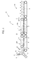
Figure 1 is a schematic side view of an apparatus according to the present invention; and -
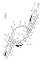
Figure 2 is a schematic perspective view of the part indicated by the arrow II inFigure 1 . - With reference to
Figure 1 , designated as a whole by 10 is an apparatus for feeding bottles B to a filling station (not illustrated). The bottles B have respective filling openings O and respective longitudinal axes A orthogonal to the filling openings O. - The
apparatus 10 comprises aconveyor 12 including abuffer 14 and aconveyor 16 for phasing and spacing bottles B, which is set in series to thebuffer 14. - The
conveyor 12 receives the bottles B set with the respective axes A oriented horizontally and with the filling openings O oriented in a mutually concordant way. - The bottles B are arranged with this orientation prior to entry into the
conveyor 12 by orientation systems of a known type. Theconveyor 12 causes the bottles B to advance in a direction of feed C, with the bottles arranged with their respective axes A aligned with one another and set horizontally. In the example illustrated, the bottles B are oriented with the respective filling openings O facing the opposite way with respect to the direction of feed C. In theconveyor 12, the bottles B maintain their initial orientation, i.e., with the filling openings O opposite to the direction of feed C in the embodiment illustrated in the figures. - The
conveyor 12 is schematically represented as being made up of various sections of belt conveyors. The constructional characteristics of theconveyor 12 are well known in the sector and do not require any indepth description. - The
buffer 14 receives a flow of bottles B at a non-regular rate and has the purpose of generating downstream a continuous flow at a constant rate, compensating for the variability in the number of bottles per minute that it receives from the feed upstream. - The phasing-and-
spacing conveyor 16 comprises twosections section first section 16A receives a continuous flow of bottles B from thebuffer 14 and supplies the bottles B to thesecond section 16B in a cadenced way. In thesecond section 16B, the bottles B are set at a distance apart from one another by a constant pitch in the direction of feed C. - The
apparatus 10 comprises atransfer wheel 18, which is able to turn about an axis D inclined with respect to the direction of feed C. The axis of rotation D of thewheel 18 is preferably inclined substantially at 45° with respect to the direction of feed C. With reference toFigure 2 , thewheel 18 is provided, on its periphery, with a plurality ofseats 20 designed to pick up and withhold the respective bottles B preferably by suction means. - The
wheel 18 and thesection 16B of theconveyor 12 are controlled in phase with one another in such a way that eachseat 20 of thewheel 18 will receive a respective bottle B. - The
wheel 18 picks up the bottles B set horizontally and at a distance apart from one another from thesection 16B of theconveyor 12 and releases the bottles after rotation through approximately 180°. Thewheel 18 releases the bottles B with the respective axes A oriented vertically and with the filling openings D facing upwards. Thewheel 18 releases the bottles B to anoutput conveyor 22. InFigure 2 , the output conveyor is schematically represented as a belt conveyor. In practice, the output conveyor may be made up of a series of wheels with a star-shaped profile designed to transfer the bottles B to a filling station in a cadenced way. - On the
output conveyor 22, the bottles B are set at a distance apart from one another by a constant pitch. The pitch between the bottles B on theoutput conveyor 22 is equal to the pitch with which the bottles B are to be supplied to the filling station. Thewheel 18 hence enables the bottles B to be set in the vertical position and automatically defines the pitch between the bottles on theoutput conveyor 22 in such a way that the bottles oriented vertically can be supplied to the filling station without any need for a subsequent repitching prior to entry into the filling station. - The solution according to the present invention is particularly advantageous in that it enables accumulation of the bottles B arranged horizontally. In this position, the bottles are much more stable, and this leads to a reduction in the number of machine jams and stoppages due to their instability.
- The system according to the present invention carries out cadencing and pitching of the bottles in the condition of maximum stability of the bottles themselves. A particularly important characteristic of the present invention is that in the pitching system according to the present invention, for families of bottles that have the same width (or thickness/height when they are laid in the horizontal position), it is possible to carry out the change of format of the bottles merely via software, modifying the speed ratios of the
conveyor 12 and of thewheel 18, without any need for modifications on the mechanisms and devices for change of format. - Downstream of the
wheel 18, the bottles B are already in phase with the processes downstream (filling, topping, etc.), and it is no longer necessary to modify the pitch between the bottles after their vertical arrangement. - In a variant, it is also possible to feed the bottles B with the filling openings oriented forwards. In this case, the axis of rotation D of the
transfer wheel 18 will be inclined in a direction opposite to what is illustrated for arranging the bottles vertically and with the openings O upwards. - Of course, without prejudice to the principle of the invention, the details of construction and the embodiments may vary widely, without thereby departing from the scope of the invention as defined by the ensuing claims.
Claims (3)
- An apparatus for feeding bottles (B) to a filling station, wherein said bottles (B) have respective filling openings (O) and a longitudinal axis (A) orthogonal to said filling openings (O), said apparatus comprising:- a conveyor (12) provided for feeding the bottles (B) in a direction of feed (C) so that they are arranged with their longitudinal axis (A) horizontal and with the filling openings (O) oriented in a mutually concordant way; and- a transfer wheel (18), which is able to turn about an axis (D) inclined with respect to said direction of feed (C) and is provided with a plurality of gripping seats (20) designed to pick up from said conveyor (12) the bottles (B) arranged with said axis (A) horizontal and to release the bottles (B) with said axis (A) oriented in the vertical direction,said apparatus being characterized in that said conveyor (12) comprises a buffer (14) and a phasing-and-spacing conveyor (16) designed to feed the bottles (B) set at a distance apart from one another by a constant pitch in said direction of feed (C) and in a phase relation with said transfer wheel (18).
- The apparatus according to Claim 1, characterized in that the axis of rotation (D) of said wheel (18) is inclined substantially at 45° with respect to said direction of feed (C).
- A method for feeding bottles (B) to a filling station, wherein said bottles have respective filling openings (O) and respective longitudinal axes (A) orthogonal to said filling openings (O), the method comprising the steps of:- feeding said bottles (B) in a direction of feed (C) so that they are arranged with said longitudinal axis (A) horizontal and with the filling openings (O) oriented in a mutually concordant way; and- picking up said bottles (B) by means of a transfer wheel (18), which is able to turn about an axis (D) inclined with respect to said direction of feed (C), said transfer wheel (18) being designed to pick up the bottles (B) with said axis (A) horizontal and to release the bottles (B) with said axis (A) oriented in the vertical direction,the method being characterized in that said bottles (B) supplied to said transfer wheel are set at a distance apart from one another in said direction of feed (C) by a constant pitch and are arranged in a phase relation with said transfer wheel (18).
Applications Claiming Priority (1)
| Application Number | Priority Date | Filing Date | Title |
|---|---|---|---|
| ITTO2010A000965A IT1403403B1 (en) | 2010-12-03 | 2010-12-03 | EQUIPMENT AND PROCEDURE FOR FEEDING BOTTLES AT A FILLING STATION |
Publications (3)
| Publication Number | Publication Date |
|---|---|
| EP2460747A1 true EP2460747A1 (en) | 2012-06-06 |
| EP2460747B1 EP2460747B1 (en) | 2013-05-29 |
| EP2460747B8 EP2460747B8 (en) | 2013-08-07 |
Family
ID=43737357
Family Applications (1)
| Application Number | Title | Priority Date | Filing Date |
|---|---|---|---|
| EP20110188610 Active EP2460747B8 (en) | 2010-12-03 | 2011-11-10 | Apparatus and method for feeding bottles to a filling station |
Country Status (4)
| Country | Link |
|---|---|
| EP (1) | EP2460747B8 (en) |
| DK (1) | DK2460747T3 (en) |
| ES (1) | ES2423659T3 (en) |
| IT (1) | IT1403403B1 (en) |
Cited By (7)
| Publication number | Priority date | Publication date | Assignee | Title |
|---|---|---|---|---|
| EP2628584B1 (en) * | 2012-02-16 | 2014-06-25 | Krones AG | Transporting apparatus and transporting method for container handling installation, and blowing machine |
| WO2014133610A3 (en) * | 2013-02-27 | 2014-12-11 | Graham Packaging Company, L.P. | Automatic rotary transfer apparatus and method |
| EP2720036A3 (en) * | 2012-10-12 | 2015-01-07 | Seidenader Maschinenbau GmbH | Device for inspecting products |
| CN104340599A (en) * | 2013-07-26 | 2015-02-11 | 克朗斯股份公司 | Conveyor belt for transporting bottles |
| CN108972685A (en) * | 2018-07-28 | 2018-12-11 | 滁州安阳智能科技有限公司 | A kind of tear-gas device bottle body recyclable device |
| EP3222532B1 (en) | 2016-03-21 | 2018-12-19 | G.D Societa' Per Azioni | Orientation unit and method for causing a change in orientation of a parallelepiped-shaped article in a packing machine |
| JP2019131362A (en) * | 2018-01-31 | 2019-08-08 | 大森機械工業株式会社 | Article take-out device |
Citations (3)
| Publication number | Priority date | Publication date | Assignee | Title |
|---|---|---|---|---|
| US2195625A (en) * | 1937-07-28 | 1940-04-02 | Anigraphic Process Inc | Machine for printing on jars |
| FR2499952A1 (en) * | 1981-02-17 | 1982-08-20 | Cugnart Pascal | Feed to tilt and lift line of bottles - has conical rotor with supports on periphery to hold bottles |
| US5421447A (en) * | 1992-04-07 | 1995-06-06 | Omega Design Corp. | High rate transfer wheel for orienting unscrambled containers |
-
2010
- 2010-12-03 IT ITTO2010A000965A patent/IT1403403B1/en active
-
2011
- 2011-11-10 DK DK11188610T patent/DK2460747T3/en active
- 2011-11-10 ES ES11188610T patent/ES2423659T3/en active Active
- 2011-11-10 EP EP20110188610 patent/EP2460747B8/en active Active
Patent Citations (3)
| Publication number | Priority date | Publication date | Assignee | Title |
|---|---|---|---|---|
| US2195625A (en) * | 1937-07-28 | 1940-04-02 | Anigraphic Process Inc | Machine for printing on jars |
| FR2499952A1 (en) * | 1981-02-17 | 1982-08-20 | Cugnart Pascal | Feed to tilt and lift line of bottles - has conical rotor with supports on periphery to hold bottles |
| US5421447A (en) * | 1992-04-07 | 1995-06-06 | Omega Design Corp. | High rate transfer wheel for orienting unscrambled containers |
Cited By (12)
| Publication number | Priority date | Publication date | Assignee | Title |
|---|---|---|---|---|
| EP2628584B1 (en) * | 2012-02-16 | 2014-06-25 | Krones AG | Transporting apparatus and transporting method for container handling installation, and blowing machine |
| US8926314B2 (en) | 2012-02-16 | 2015-01-06 | Krones Ag | Transport device and transport method for container treatment plant as well as blow molding machine |
| EP2720036A3 (en) * | 2012-10-12 | 2015-01-07 | Seidenader Maschinenbau GmbH | Device for inspecting products |
| WO2014133610A3 (en) * | 2013-02-27 | 2014-12-11 | Graham Packaging Company, L.P. | Automatic rotary transfer apparatus and method |
| US9181036B2 (en) | 2013-02-27 | 2015-11-10 | Graham Packaging Company, L.P. | Automatic rotary transfer apparatus and method |
| CN105050925A (en) * | 2013-02-27 | 2015-11-11 | 格莱汉姆包装公司 | Automatic rotary transfer apparatus and method |
| CN104340599A (en) * | 2013-07-26 | 2015-02-11 | 克朗斯股份公司 | Conveyor belt for transporting bottles |
| EP3222532B1 (en) | 2016-03-21 | 2018-12-19 | G.D Societa' Per Azioni | Orientation unit and method for causing a change in orientation of a parallelepiped-shaped article in a packing machine |
| EP3222532B2 (en) † | 2016-03-21 | 2023-08-16 | G.D Societa' Per Azioni | Orientation unit and method for causing a change in orientation of a parallelepiped-shaped article in a packing machine |
| JP2019131362A (en) * | 2018-01-31 | 2019-08-08 | 大森機械工業株式会社 | Article take-out device |
| WO2019150709A1 (en) * | 2018-01-31 | 2019-08-08 | 大森機械工業株式会社 | Article extraction device |
| CN108972685A (en) * | 2018-07-28 | 2018-12-11 | 滁州安阳智能科技有限公司 | A kind of tear-gas device bottle body recyclable device |
Also Published As
| Publication number | Publication date |
|---|---|
| EP2460747B8 (en) | 2013-08-07 |
| DK2460747T3 (en) | 2013-06-24 |
| EP2460747B1 (en) | 2013-05-29 |
| ES2423659T3 (en) | 2013-09-23 |
| ITTO20100965A1 (en) | 2011-03-04 |
| IT1403403B1 (en) | 2013-10-17 |
Similar Documents
| Publication | Publication Date | Title |
|---|---|---|
| EP2460747B1 (en) | Apparatus and method for feeding bottles to a filling station | |
| US8336700B2 (en) | Transport system for moving a plurality of containers through a plurality of work stations | |
| EP2107018B1 (en) | Method and device for compiling and aligning container groups | |
| CN108698771B (en) | Delivery system with multiple outlets | |
| US20130239525A1 (en) | Method and Device for Filling a Multi-Row Packaging Tray with Fragmented Products | |
| CN109863089B (en) | Method and device for portion packaging of flat products | |
| US9399529B2 (en) | Automated product engager, transporter and patterened depositor system | |
| DE102008055471A1 (en) | Method and device for assembling and aligning container groups | |
| US8939272B2 (en) | Article orienting machine | |
| CN110431095A (en) | For being layered the production of the product batches of stacking | |
| JP5359060B2 (en) | Container delivery device | |
| CN105164033A (en) | Method and system for transporting objects | |
| US10926961B2 (en) | Multiline transfer of product | |
| US10611584B2 (en) | Method and device for grouping product blanks | |
| US10336553B2 (en) | Method and handling device | |
| US10773842B2 (en) | Labeling machine and method of producing multipacks | |
| US10259660B2 (en) | Method and device for conveying and grouping fragmented products | |
| JP4960267B2 (en) | Article supply equipment | |
| JP7344901B2 (en) | Transfer of product between transit zone and collection surface | |
| JP6308887B2 (en) | Accumulator | |
| CN210116978U (en) | Confluence conveying device | |
| CN201472734U (en) | Cup discharging device of fill-seal packing machine | |
| CN101746602B (en) | Device and method for grouping items | |
| US20130174519A1 (en) | Apparatus and method for manoeuvring products | |
| JP2013541480A (en) | Mounting apparatus for pallets, and method for arranging package units in rows and / or columns on pallets for transportation |
Legal Events
| Date | Code | Title | Description |
|---|---|---|---|
| PUAI | Public reference made under article 153(3) epc to a published international application that has entered the european phase |
Free format text: ORIGINAL CODE: 0009012 |
|
| AK | Designated contracting states |
Kind code of ref document: A1 Designated state(s): AL AT BE BG CH CY CZ DE DK EE ES FI FR GB GR HR HU IE IS IT LI LT LU LV MC MK MT NL NO PL PT RO RS SE SI SK SM TR |
|
| AX | Request for extension of the european patent |
Extension state: BA ME |
|
| 17P | Request for examination filed |
Effective date: 20121123 |
|
| GRAP | Despatch of communication of intention to grant a patent |
Free format text: ORIGINAL CODE: EPIDOSNIGR1 |
|
| RIC1 | Information provided on ipc code assigned before grant |
Ipc: B65G 47/24 20060101ALI20121211BHEP Ipc: B65G 47/84 20060101ALI20121211BHEP Ipc: B65G 29/02 20060101AFI20121211BHEP |
|
| GRAS | Grant fee paid |
Free format text: ORIGINAL CODE: EPIDOSNIGR3 |
|
| GRAA | (expected) grant |
Free format text: ORIGINAL CODE: 0009210 |
|
| AK | Designated contracting states |
Kind code of ref document: B1 Designated state(s): AL AT BE BG CH CY CZ DE DK EE ES FI FR GB GR HR HU IE IS IT LI LT LU LV MC MK MT NL NO PL PT RO RS SE SI SK SM TR |
|
| REG | Reference to a national code |
Ref country code: GB Ref legal event code: FG4D |
|
| REG | Reference to a national code |
Ref country code: CH Ref legal event code: EP |
|
| REG | Reference to a national code |
Ref country code: AT Ref legal event code: REF Ref document number: 614261 Country of ref document: AT Kind code of ref document: T Effective date: 20130615 |
|
| REG | Reference to a national code |
Ref country code: DK Ref legal event code: T3 |
|
| REG | Reference to a national code |
Ref country code: IE Ref legal event code: FG4D |
|
| REG | Reference to a national code |
Ref country code: CH Ref legal event code: PK Free format text: RETTIFICA TITOLARE Ref country code: CH Ref legal event code: NV Representative=s name: ISLER AND PEDRAZZINI AG, CH |
|
| RAP2 | Party data changed (patent owner data changed or rights of a patent transferred) |
Owner name: FAMECCANICA.DATA S.P.A. |
|
| REG | Reference to a national code |
Ref country code: DE Ref legal event code: R096 Ref document number: 602011001822 Country of ref document: DE Effective date: 20130725 |
|
| REG | Reference to a national code |
Ref country code: SE Ref legal event code: TRGR |
|
| REG | Reference to a national code |
Ref country code: ES Ref legal event code: FG2A Ref document number: 2423659 Country of ref document: ES Kind code of ref document: T3 Effective date: 20130923 |
|
| REG | Reference to a national code |
Ref country code: AT Ref legal event code: MK05 Ref document number: 614261 Country of ref document: AT Kind code of ref document: T Effective date: 20130529 |
|
| REG | Reference to a national code |
Ref country code: LT Ref legal event code: MG4D |
|
| PG25 | Lapsed in a contracting state [announced via postgrant information from national office to epo] |
Ref country code: PT Free format text: LAPSE BECAUSE OF FAILURE TO SUBMIT A TRANSLATION OF THE DESCRIPTION OR TO PAY THE FEE WITHIN THE PRESCRIBED TIME-LIMIT Effective date: 20130930 Ref country code: SI Free format text: LAPSE BECAUSE OF FAILURE TO SUBMIT A TRANSLATION OF THE DESCRIPTION OR TO PAY THE FEE WITHIN THE PRESCRIBED TIME-LIMIT Effective date: 20130529 Ref country code: NO Free format text: LAPSE BECAUSE OF FAILURE TO SUBMIT A TRANSLATION OF THE DESCRIPTION OR TO PAY THE FEE WITHIN THE PRESCRIBED TIME-LIMIT Effective date: 20130829 Ref country code: AT Free format text: LAPSE BECAUSE OF FAILURE TO SUBMIT A TRANSLATION OF THE DESCRIPTION OR TO PAY THE FEE WITHIN THE PRESCRIBED TIME-LIMIT Effective date: 20130529 Ref country code: IS Free format text: LAPSE BECAUSE OF FAILURE TO SUBMIT A TRANSLATION OF THE DESCRIPTION OR TO PAY THE FEE WITHIN THE PRESCRIBED TIME-LIMIT Effective date: 20130929 Ref country code: GR Free format text: LAPSE BECAUSE OF FAILURE TO SUBMIT A TRANSLATION OF THE DESCRIPTION OR TO PAY THE FEE WITHIN THE PRESCRIBED TIME-LIMIT Effective date: 20130830 Ref country code: LT Free format text: LAPSE BECAUSE OF FAILURE TO SUBMIT A TRANSLATION OF THE DESCRIPTION OR TO PAY THE FEE WITHIN THE PRESCRIBED TIME-LIMIT Effective date: 20130529 Ref country code: FI Free format text: LAPSE BECAUSE OF FAILURE TO SUBMIT A TRANSLATION OF THE DESCRIPTION OR TO PAY THE FEE WITHIN THE PRESCRIBED TIME-LIMIT Effective date: 20130529 |
|
| REG | Reference to a national code |
Ref country code: NL Ref legal event code: VDEP Effective date: 20130529 |
|
| PG25 | Lapsed in a contracting state [announced via postgrant information from national office to epo] |
Ref country code: HR Free format text: LAPSE BECAUSE OF FAILURE TO SUBMIT A TRANSLATION OF THE DESCRIPTION OR TO PAY THE FEE WITHIN THE PRESCRIBED TIME-LIMIT Effective date: 20130529 Ref country code: PL Free format text: LAPSE BECAUSE OF FAILURE TO SUBMIT A TRANSLATION OF THE DESCRIPTION OR TO PAY THE FEE WITHIN THE PRESCRIBED TIME-LIMIT Effective date: 20130529 Ref country code: BG Free format text: LAPSE BECAUSE OF FAILURE TO SUBMIT A TRANSLATION OF THE DESCRIPTION OR TO PAY THE FEE WITHIN THE PRESCRIBED TIME-LIMIT Effective date: 20130829 Ref country code: RS Free format text: LAPSE BECAUSE OF FAILURE TO SUBMIT A TRANSLATION OF THE DESCRIPTION OR TO PAY THE FEE WITHIN THE PRESCRIBED TIME-LIMIT Effective date: 20130529 |
|
| PG25 | Lapsed in a contracting state [announced via postgrant information from national office to epo] |
Ref country code: LV Free format text: LAPSE BECAUSE OF FAILURE TO SUBMIT A TRANSLATION OF THE DESCRIPTION OR TO PAY THE FEE WITHIN THE PRESCRIBED TIME-LIMIT Effective date: 20130529 |
|
| PG25 | Lapsed in a contracting state [announced via postgrant information from national office to epo] |
Ref country code: SK Free format text: LAPSE BECAUSE OF FAILURE TO SUBMIT A TRANSLATION OF THE DESCRIPTION OR TO PAY THE FEE WITHIN THE PRESCRIBED TIME-LIMIT Effective date: 20130529 Ref country code: CZ Free format text: LAPSE BECAUSE OF FAILURE TO SUBMIT A TRANSLATION OF THE DESCRIPTION OR TO PAY THE FEE WITHIN THE PRESCRIBED TIME-LIMIT Effective date: 20130529 Ref country code: EE Free format text: LAPSE BECAUSE OF FAILURE TO SUBMIT A TRANSLATION OF THE DESCRIPTION OR TO PAY THE FEE WITHIN THE PRESCRIBED TIME-LIMIT Effective date: 20130529 |
|
| PG25 | Lapsed in a contracting state [announced via postgrant information from national office to epo] |
Ref country code: NL Free format text: LAPSE BECAUSE OF FAILURE TO SUBMIT A TRANSLATION OF THE DESCRIPTION OR TO PAY THE FEE WITHIN THE PRESCRIBED TIME-LIMIT Effective date: 20130529 Ref country code: RO Free format text: LAPSE BECAUSE OF FAILURE TO SUBMIT A TRANSLATION OF THE DESCRIPTION OR TO PAY THE FEE WITHIN THE PRESCRIBED TIME-LIMIT Effective date: 20130529 |
|
| PLBE | No opposition filed within time limit |
Free format text: ORIGINAL CODE: 0009261 |
|
| STAA | Information on the status of an ep patent application or granted ep patent |
Free format text: STATUS: NO OPPOSITION FILED WITHIN TIME LIMIT |
|
| 26N | No opposition filed |
Effective date: 20140303 |
|
| REG | Reference to a national code |
Ref country code: DE Ref legal event code: R097 Ref document number: 602011001822 Country of ref document: DE Effective date: 20140303 |
|
| REG | Reference to a national code |
Ref country code: IE Ref legal event code: MM4A |
|
| PG25 | Lapsed in a contracting state [announced via postgrant information from national office to epo] |
Ref country code: IE Free format text: LAPSE BECAUSE OF NON-PAYMENT OF DUE FEES Effective date: 20131110 |
|
| PG25 | Lapsed in a contracting state [announced via postgrant information from national office to epo] |
Ref country code: SM Free format text: LAPSE BECAUSE OF FAILURE TO SUBMIT A TRANSLATION OF THE DESCRIPTION OR TO PAY THE FEE WITHIN THE PRESCRIBED TIME-LIMIT Effective date: 20130529 |
|
| PG25 | Lapsed in a contracting state [announced via postgrant information from national office to epo] |
Ref country code: CY Free format text: LAPSE BECAUSE OF FAILURE TO SUBMIT A TRANSLATION OF THE DESCRIPTION OR TO PAY THE FEE WITHIN THE PRESCRIBED TIME-LIMIT Effective date: 20130529 Ref country code: TR Free format text: LAPSE BECAUSE OF FAILURE TO SUBMIT A TRANSLATION OF THE DESCRIPTION OR TO PAY THE FEE WITHIN THE PRESCRIBED TIME-LIMIT Effective date: 20130529 |
|
| PG25 | Lapsed in a contracting state [announced via postgrant information from national office to epo] |
Ref country code: MK Free format text: LAPSE BECAUSE OF FAILURE TO SUBMIT A TRANSLATION OF THE DESCRIPTION OR TO PAY THE FEE WITHIN THE PRESCRIBED TIME-LIMIT Effective date: 20130529 Ref country code: LU Free format text: LAPSE BECAUSE OF NON-PAYMENT OF DUE FEES Effective date: 20131110 Ref country code: MC Free format text: LAPSE BECAUSE OF FAILURE TO SUBMIT A TRANSLATION OF THE DESCRIPTION OR TO PAY THE FEE WITHIN THE PRESCRIBED TIME-LIMIT Effective date: 20130529 Ref country code: HU Free format text: LAPSE BECAUSE OF FAILURE TO SUBMIT A TRANSLATION OF THE DESCRIPTION OR TO PAY THE FEE WITHIN THE PRESCRIBED TIME-LIMIT; INVALID AB INITIO Effective date: 20111110 |
|
| PG25 | Lapsed in a contracting state [announced via postgrant information from national office to epo] |
Ref country code: MT Free format text: LAPSE BECAUSE OF FAILURE TO SUBMIT A TRANSLATION OF THE DESCRIPTION OR TO PAY THE FEE WITHIN THE PRESCRIBED TIME-LIMIT Effective date: 20130529 |
|
| REG | Reference to a national code |
Ref country code: FR Ref legal event code: PLFP Year of fee payment: 5 |
|
| REG | Reference to a national code |
Ref country code: FR Ref legal event code: PLFP Year of fee payment: 6 |
|
| REG | Reference to a national code |
Ref country code: FR Ref legal event code: PLFP Year of fee payment: 7 |
|
| PG25 | Lapsed in a contracting state [announced via postgrant information from national office to epo] |
Ref country code: AL Free format text: LAPSE BECAUSE OF FAILURE TO SUBMIT A TRANSLATION OF THE DESCRIPTION OR TO PAY THE FEE WITHIN THE PRESCRIBED TIME-LIMIT Effective date: 20130529 |
|
| PGFP | Annual fee paid to national office [announced via postgrant information from national office to epo] |
Ref country code: DK Payment date: 20181126 Year of fee payment: 8 |
|
| REG | Reference to a national code |
Ref country code: DK Ref legal event code: EBP Effective date: 20191130 |
|
| REG | Reference to a national code |
Ref country code: DE Ref legal event code: R082 Ref document number: 602011001822 Country of ref document: DE Representative=s name: BARDEHLE PAGENBERG PARTNERSCHAFT MBB PATENTANW, DE Ref country code: DE Ref legal event code: R081 Ref document number: 602011001822 Country of ref document: DE Owner name: FAMECCANICA.DATA S.P.A., SAN GIOVANNI TEATINO, IT Free format text: FORMER OWNER: FAMECCANICA.DATA S.P.A., PESCARA, IT |
|
| REG | Reference to a national code |
Ref country code: CH Ref legal event code: PCOW Free format text: NEW ADDRESS: VIA ATERNO, 136, 66020 SAN GIOVANNI TEATINO (CHIETI) (IT) |
|
| PG25 | Lapsed in a contracting state [announced via postgrant information from national office to epo] |
Ref country code: DK Free format text: LAPSE BECAUSE OF NON-PAYMENT OF DUE FEES Effective date: 20191130 |
|
| PGFP | Annual fee paid to national office [announced via postgrant information from national office to epo] |
Ref country code: BE Payment date: 20221128 Year of fee payment: 12 |
|
| PGFP | Annual fee paid to national office [announced via postgrant information from national office to epo] |
Ref country code: GB Payment date: 20231127 Year of fee payment: 13 |
|
| PGFP | Annual fee paid to national office [announced via postgrant information from national office to epo] |
Ref country code: ES Payment date: 20231201 Year of fee payment: 13 |
|
| PGFP | Annual fee paid to national office [announced via postgrant information from national office to epo] |
Ref country code: SE Payment date: 20231127 Year of fee payment: 13 Ref country code: IT Payment date: 20231122 Year of fee payment: 13 Ref country code: FR Payment date: 20231127 Year of fee payment: 13 Ref country code: DE Payment date: 20231129 Year of fee payment: 13 Ref country code: CH Payment date: 20231201 Year of fee payment: 13 |
|
| PGFP | Annual fee paid to national office [announced via postgrant information from national office to epo] |
Ref country code: BE Payment date: 20231127 Year of fee payment: 13 |