EP2460654A1 - Waterproof member and method of producing the same - Google Patents
Waterproof member and method of producing the same Download PDFInfo
- Publication number
- EP2460654A1 EP2460654A1 EP20110191689 EP11191689A EP2460654A1 EP 2460654 A1 EP2460654 A1 EP 2460654A1 EP 20110191689 EP20110191689 EP 20110191689 EP 11191689 A EP11191689 A EP 11191689A EP 2460654 A1 EP2460654 A1 EP 2460654A1
- Authority
- EP
- European Patent Office
- Prior art keywords
- polymer sheet
- resin
- waterproof member
- resin layer
- resin solution
- Prior art date
- Legal status (The legal status is an assumption and is not a legal conclusion. Google has not performed a legal analysis and makes no representation as to the accuracy of the status listed.)
- Withdrawn
Links
Images


Classifications
-
- B—PERFORMING OPERATIONS; TRANSPORTING
- B29—WORKING OF PLASTICS; WORKING OF SUBSTANCES IN A PLASTIC STATE IN GENERAL
- B29C—SHAPING OR JOINING OF PLASTICS; SHAPING OF MATERIAL IN A PLASTIC STATE, NOT OTHERWISE PROVIDED FOR; AFTER-TREATMENT OF THE SHAPED PRODUCTS, e.g. REPAIRING
- B29C45/00—Injection moulding, i.e. forcing the required volume of moulding material through a nozzle into a closed mould; Apparatus therefor
- B29C45/0053—Injection moulding, i.e. forcing the required volume of moulding material through a nozzle into a closed mould; Apparatus therefor combined with a final operation, e.g. shaping
- B29C45/006—Joining parts moulded in separate cavities
-
- B—PERFORMING OPERATIONS; TRANSPORTING
- B29—WORKING OF PLASTICS; WORKING OF SUBSTANCES IN A PLASTIC STATE IN GENERAL
- B29C—SHAPING OR JOINING OF PLASTICS; SHAPING OF MATERIAL IN A PLASTIC STATE, NOT OTHERWISE PROVIDED FOR; AFTER-TREATMENT OF THE SHAPED PRODUCTS, e.g. REPAIRING
- B29C43/00—Compression moulding, i.e. applying external pressure to flow the moulding material; Apparatus therefor
- B29C43/02—Compression moulding, i.e. applying external pressure to flow the moulding material; Apparatus therefor of articles of definite length, i.e. discrete articles
- B29C43/18—Compression moulding, i.e. applying external pressure to flow the moulding material; Apparatus therefor of articles of definite length, i.e. discrete articles incorporating preformed parts or layers, e.g. compression moulding around inserts or for coating articles
-
- B—PERFORMING OPERATIONS; TRANSPORTING
- B29—WORKING OF PLASTICS; WORKING OF SUBSTANCES IN A PLASTIC STATE IN GENERAL
- B29C—SHAPING OR JOINING OF PLASTICS; SHAPING OF MATERIAL IN A PLASTIC STATE, NOT OTHERWISE PROVIDED FOR; AFTER-TREATMENT OF THE SHAPED PRODUCTS, e.g. REPAIRING
- B29C35/00—Heating, cooling or curing, e.g. crosslinking or vulcanising; Apparatus therefor
- B29C35/02—Heating or curing, e.g. crosslinking or vulcanizing during moulding, e.g. in a mould
- B29C35/08—Heating or curing, e.g. crosslinking or vulcanizing during moulding, e.g. in a mould by wave energy or particle radiation
- B29C35/0805—Heating or curing, e.g. crosslinking or vulcanizing during moulding, e.g. in a mould by wave energy or particle radiation using electromagnetic radiation
- B29C2035/0827—Heating or curing, e.g. crosslinking or vulcanizing during moulding, e.g. in a mould by wave energy or particle radiation using electromagnetic radiation using UV radiation
-
- B—PERFORMING OPERATIONS; TRANSPORTING
- B29—WORKING OF PLASTICS; WORKING OF SUBSTANCES IN A PLASTIC STATE IN GENERAL
- B29C—SHAPING OR JOINING OF PLASTICS; SHAPING OF MATERIAL IN A PLASTIC STATE, NOT OTHERWISE PROVIDED FOR; AFTER-TREATMENT OF THE SHAPED PRODUCTS, e.g. REPAIRING
- B29C45/00—Injection moulding, i.e. forcing the required volume of moulding material through a nozzle into a closed mould; Apparatus therefor
- B29C45/0053—Injection moulding, i.e. forcing the required volume of moulding material through a nozzle into a closed mould; Apparatus therefor combined with a final operation, e.g. shaping
- B29C45/006—Joining parts moulded in separate cavities
- B29C2045/0067—Joining parts moulded in separate cavities interposing an insert between the parts to be assembled
-
- B—PERFORMING OPERATIONS; TRANSPORTING
- B29—WORKING OF PLASTICS; WORKING OF SUBSTANCES IN A PLASTIC STATE IN GENERAL
- B29C—SHAPING OR JOINING OF PLASTICS; SHAPING OF MATERIAL IN A PLASTIC STATE, NOT OTHERWISE PROVIDED FOR; AFTER-TREATMENT OF THE SHAPED PRODUCTS, e.g. REPAIRING
- B29C45/00—Injection moulding, i.e. forcing the required volume of moulding material through a nozzle into a closed mould; Apparatus therefor
- B29C45/0053—Injection moulding, i.e. forcing the required volume of moulding material through a nozzle into a closed mould; Apparatus therefor combined with a final operation, e.g. shaping
- B29C2045/0075—Injection moulding, i.e. forcing the required volume of moulding material through a nozzle into a closed mould; Apparatus therefor combined with a final operation, e.g. shaping curing or polymerising by irradiation
-
- B—PERFORMING OPERATIONS; TRANSPORTING
- B29—WORKING OF PLASTICS; WORKING OF SUBSTANCES IN A PLASTIC STATE IN GENERAL
- B29C—SHAPING OR JOINING OF PLASTICS; SHAPING OF MATERIAL IN A PLASTIC STATE, NOT OTHERWISE PROVIDED FOR; AFTER-TREATMENT OF THE SHAPED PRODUCTS, e.g. REPAIRING
- B29C65/00—Joining or sealing of preformed parts, e.g. welding of plastics materials; Apparatus therefor
- B29C65/02—Joining or sealing of preformed parts, e.g. welding of plastics materials; Apparatus therefor by heating, with or without pressure
- B29C65/14—Joining or sealing of preformed parts, e.g. welding of plastics materials; Apparatus therefor by heating, with or without pressure using wave energy, i.e. electromagnetic radiation, or particle radiation
- B29C65/1403—Joining or sealing of preformed parts, e.g. welding of plastics materials; Apparatus therefor by heating, with or without pressure using wave energy, i.e. electromagnetic radiation, or particle radiation characterised by the type of electromagnetic or particle radiation
- B29C65/1406—Ultraviolet [UV] radiation
-
- B—PERFORMING OPERATIONS; TRANSPORTING
- B29—WORKING OF PLASTICS; WORKING OF SUBSTANCES IN A PLASTIC STATE IN GENERAL
- B29C—SHAPING OR JOINING OF PLASTICS; SHAPING OF MATERIAL IN A PLASTIC STATE, NOT OTHERWISE PROVIDED FOR; AFTER-TREATMENT OF THE SHAPED PRODUCTS, e.g. REPAIRING
- B29C65/00—Joining or sealing of preformed parts, e.g. welding of plastics materials; Apparatus therefor
- B29C65/48—Joining or sealing of preformed parts, e.g. welding of plastics materials; Apparatus therefor using adhesives, i.e. using supplementary joining material; solvent bonding
- B29C65/50—Joining or sealing of preformed parts, e.g. welding of plastics materials; Apparatus therefor using adhesives, i.e. using supplementary joining material; solvent bonding using adhesive tape, e.g. thermoplastic tape; using threads or the like
- B29C65/5007—Joining or sealing of preformed parts, e.g. welding of plastics materials; Apparatus therefor using adhesives, i.e. using supplementary joining material; solvent bonding using adhesive tape, e.g. thermoplastic tape; using threads or the like characterised by the structure of said adhesive tape, threads or the like
- B29C65/5021—Joining or sealing of preformed parts, e.g. welding of plastics materials; Apparatus therefor using adhesives, i.e. using supplementary joining material; solvent bonding using adhesive tape, e.g. thermoplastic tape; using threads or the like characterised by the structure of said adhesive tape, threads or the like being multi-layered
-
- B—PERFORMING OPERATIONS; TRANSPORTING
- B29—WORKING OF PLASTICS; WORKING OF SUBSTANCES IN A PLASTIC STATE IN GENERAL
- B29C—SHAPING OR JOINING OF PLASTICS; SHAPING OF MATERIAL IN A PLASTIC STATE, NOT OTHERWISE PROVIDED FOR; AFTER-TREATMENT OF THE SHAPED PRODUCTS, e.g. REPAIRING
- B29C65/00—Joining or sealing of preformed parts, e.g. welding of plastics materials; Apparatus therefor
- B29C65/48—Joining or sealing of preformed parts, e.g. welding of plastics materials; Apparatus therefor using adhesives, i.e. using supplementary joining material; solvent bonding
- B29C65/50—Joining or sealing of preformed parts, e.g. welding of plastics materials; Apparatus therefor using adhesives, i.e. using supplementary joining material; solvent bonding using adhesive tape, e.g. thermoplastic tape; using threads or the like
- B29C65/5057—Joining or sealing of preformed parts, e.g. welding of plastics materials; Apparatus therefor using adhesives, i.e. using supplementary joining material; solvent bonding using adhesive tape, e.g. thermoplastic tape; using threads or the like positioned between the surfaces to be joined
-
- B—PERFORMING OPERATIONS; TRANSPORTING
- B29—WORKING OF PLASTICS; WORKING OF SUBSTANCES IN A PLASTIC STATE IN GENERAL
- B29C—SHAPING OR JOINING OF PLASTICS; SHAPING OF MATERIAL IN A PLASTIC STATE, NOT OTHERWISE PROVIDED FOR; AFTER-TREATMENT OF THE SHAPED PRODUCTS, e.g. REPAIRING
- B29C66/00—General aspects of processes or apparatus for joining preformed parts
- B29C66/01—General aspects dealing with the joint area or with the area to be joined
- B29C66/05—Particular design of joint configurations
- B29C66/10—Particular design of joint configurations particular design of the joint cross-sections
- B29C66/11—Joint cross-sections comprising a single joint-segment, i.e. one of the parts to be joined comprising a single joint-segment in the joint cross-section
- B29C66/112—Single lapped joints
- B29C66/1122—Single lap to lap joints, i.e. overlap joints
-
- B—PERFORMING OPERATIONS; TRANSPORTING
- B29—WORKING OF PLASTICS; WORKING OF SUBSTANCES IN A PLASTIC STATE IN GENERAL
- B29K—INDEXING SCHEME ASSOCIATED WITH SUBCLASSES B29B, B29C OR B29D, RELATING TO MOULDING MATERIALS OR TO MATERIALS FOR MOULDS, REINFORCEMENTS, FILLERS OR PREFORMED PARTS, e.g. INSERTS
- B29K2995/00—Properties of moulding materials, reinforcements, fillers, preformed parts or moulds
- B29K2995/0037—Other properties
- B29K2995/0068—Permeability to liquids; Adsorption
- B29K2995/0069—Permeability to liquids; Adsorption non-permeable
-
- Y—GENERAL TAGGING OF NEW TECHNOLOGICAL DEVELOPMENTS; GENERAL TAGGING OF CROSS-SECTIONAL TECHNOLOGIES SPANNING OVER SEVERAL SECTIONS OF THE IPC; TECHNICAL SUBJECTS COVERED BY FORMER USPC CROSS-REFERENCE ART COLLECTIONS [XRACs] AND DIGESTS
- Y10—TECHNICAL SUBJECTS COVERED BY FORMER USPC
- Y10T—TECHNICAL SUBJECTS COVERED BY FORMER US CLASSIFICATION
- Y10T428/00—Stock material or miscellaneous articles
- Y10T428/26—Web or sheet containing structurally defined element or component, the element or component having a specified physical dimension
- Y10T428/263—Coating layer not in excess of 5 mils thick or equivalent
-
- Y—GENERAL TAGGING OF NEW TECHNOLOGICAL DEVELOPMENTS; GENERAL TAGGING OF CROSS-SECTIONAL TECHNOLOGIES SPANNING OVER SEVERAL SECTIONS OF THE IPC; TECHNICAL SUBJECTS COVERED BY FORMER USPC CROSS-REFERENCE ART COLLECTIONS [XRACs] AND DIGESTS
- Y10—TECHNICAL SUBJECTS COVERED BY FORMER USPC
- Y10T—TECHNICAL SUBJECTS COVERED BY FORMER US CLASSIFICATION
- Y10T428/00—Stock material or miscellaneous articles
- Y10T428/26—Web or sheet containing structurally defined element or component, the element or component having a specified physical dimension
- Y10T428/266—Web or sheet containing structurally defined element or component, the element or component having a specified physical dimension of base or substrate
-
- Y—GENERAL TAGGING OF NEW TECHNOLOGICAL DEVELOPMENTS; GENERAL TAGGING OF CROSS-SECTIONAL TECHNOLOGIES SPANNING OVER SEVERAL SECTIONS OF THE IPC; TECHNICAL SUBJECTS COVERED BY FORMER USPC CROSS-REFERENCE ART COLLECTIONS [XRACs] AND DIGESTS
- Y10—TECHNICAL SUBJECTS COVERED BY FORMER USPC
- Y10T—TECHNICAL SUBJECTS COVERED BY FORMER US CLASSIFICATION
- Y10T428/00—Stock material or miscellaneous articles
- Y10T428/31504—Composite [nonstructural laminate]
- Y10T428/31507—Of polycarbonate
-
- Y—GENERAL TAGGING OF NEW TECHNOLOGICAL DEVELOPMENTS; GENERAL TAGGING OF CROSS-SECTIONAL TECHNOLOGIES SPANNING OVER SEVERAL SECTIONS OF THE IPC; TECHNICAL SUBJECTS COVERED BY FORMER USPC CROSS-REFERENCE ART COLLECTIONS [XRACs] AND DIGESTS
- Y10—TECHNICAL SUBJECTS COVERED BY FORMER USPC
- Y10T—TECHNICAL SUBJECTS COVERED BY FORMER US CLASSIFICATION
- Y10T428/00—Stock material or miscellaneous articles
- Y10T428/31504—Composite [nonstructural laminate]
- Y10T428/31855—Of addition polymer from unsaturated monomers
- Y10T428/31931—Polyene monomer-containing
Definitions
- the present invention relates to a waterproof member and a method of producing the same. More particularly, to a waterproof member and a method of producing the member for protecting internal components of a mobile terminal from moisture damage.
- the conventional rubber or silicon may have difficulty in maintaining its shape (regularity), and as a result, it may be difficult to perform assembling work with the conventional rubber or silicon. Accordingly, the assembling of the conventional waterproof members may result in poor operation efficiency.
- rubber or silicon may be lengthened due to its ductility, which may result in inconsistent shape. Accordingly, the waterproof capacity may gradually decrease for these reasons with a prolonged use.
- Exemplary embodiments of the present invention provide a water proofing member and a method for producing the same.
- Exemplary embodiments of the present invention provide a polymer sheet, and an ultraviolet (UV) resin layer adhered to a first surface and a second surface of the polymer sheet.
- UV ultraviolet
- Exemplary embodiments of the present invention provide a method for producing a waterproof member that including injecting a first ultraviolet (UV) resin solution into a first resin molding; placing a polymer sheet onto the first UV resin solution; compressing the polymer sheet and the first UV resin solution to be adhered to each other; and curing a first UV resin layer on the polymer sheet by irradiating UV into the first UV resin solution.
- UV ultraviolet
- Exemplary embodiments of the present invention provide a member to prevent liquid from entering into an area including a first material formed by ultraviolet (UV) irradiation; a second material; and a third material formed by UV irradiation, in which the first material and the third material sandwich the second material.
- a first material formed by ultraviolet (UV) irradiation a first material formed by ultraviolet (UV) irradiation
- a second material a second material
- a third material formed by UV irradiation in which the first material and the third material sandwich the second material.
- Exemplary embodiments of the present invention provide a terminal including a waterproof member to block liquid from entry, in which the waterproof member includes a polymer sheet, and an ultraviolet (UV) resin layer adhered to a first surface and a second surface of the polymer sheet.
- the waterproof member includes a polymer sheet, and an ultraviolet (UV) resin layer adhered to a first surface and a second surface of the polymer sheet.
- UV ultraviolet
- FIG. 1 is a schematic cross-sectional view of a conventional waterproof member.
- FIG. 2 is a cross-sectional view of a waterproof member according to an exemplary embodiment of the invention.
- FIG. 3 is a front view of the waterproof member shown in FIG. 2 according to an exemplary embodiment of the invention.
- FIG. 4 is a flow chart illustrating a method of producing a waterproof member according to an exemplary embodiment of the invention.
- FIG. 5 is a flow chart illustrating a method of producing a waterproof member according to an exemplary embodiment of the invention.
- FIG. 1 is a schematic cross-sectional view of a conventional waterproof member.
- the conventional waterproof member includes a rubber or silicone to act as a seal against moisture.
- FIG. 2 is a cross-sectional view of a waterproof member according to an exemplary embodiment of the invention.
- the waterproof member includes one or more layers of ultraviolet (UV) resin and a polymer sheet to provide protection against moisture. More specifically, the waterproof member includes a polymer sheet capable of maintaining regularity and materials having a compressive and restoring forces sandwiched on top and bottom of the polymer sheet. In addition, one or more layers of soft UV resin, which may exhibit compressive and restoring force, are provided on both sides of the polymer sheet.
- UV ultraviolet
- the waterproof member according to the exemplary embodiment of the invention includes a polymer sheet and soft UV resin layers assembled on top and bottom of the polymer sheet, the invention is not limited to such configuration or the number of resin layers and polymer sheets.
- the polymer sheet capable of maintaining regularity may be used in the water proof member. More specifically, a polymer sheet having high adhesiveness with respect to soft UV resin may be preferably used.
- a PC Polycarbonate
- PET Polyethylene Terephthalate
- a thickness of the polymer sheet may preferably be in a range of 150 to 300 ⁇ m. If the polymer sheet is too thin, it may be difficult to maintain regularity thereof. If the polymer sheet is too thick, the compressive strength thereof may be lowered, and may lower waterproofing efficiency.
- the soft UV resin used may be a resin that is commercially available or synthesized.
- the soft resins with a thickness of 300 ⁇ m to 500 ⁇ m may provide acceptable comprehensive strength.
- a curing agent may be added.
- the soft UV resin may be produced to further include functional additives, such as an anti-foaming agent, an extinction agent, or the like.
- a thickness of the soft UV resin layer is preferably in a range of 300 ⁇ m to 500 ⁇ m. If the UV resin layer is too thin, the compressive strength thereof may be lowered, thereby undesirably lowering waterproof efficiency. If the soft UV resin layer is too thick, the regularity thereof may deteriorate.
- a resin generally classified as a soft in view of the relative softness of UV resin may be used as the soft UV resin in the waterproof member.
- a resin layer resulting from curing preferably has Shore hardness in a range of 40° to 60°. If the waterproof member has an excessively high hardness, deformation may occur in the course of producing the waterproof member. In addition, if an external force is applied, cracks may be generated and compression may not be performed properly. If the waterproof member has an excessively low hardness, the waterproof member may be lengthened or may have poor restoration capacity after a prolonged use, thus causing the waterproof member to be deformed due to an external force applied thereto.
- the waterproof member according to the present invention can be applied to assembled machines and electronic devices.
- the waterproof member according to the present invention can be applied to a variety of devices that may benefit from waterproofing capabilities. Such devices may find difficulty in providing waterproofing due to a gap between assembled components, like a mobile communication terminals, such as PMP, PDA, cellular phones, and the like.
- the waterproof member sealing a gap created between upper and lower cases of a cellular phone as provided by the presently disclosed waterproof member may be shaped as connected rings, for example, as shown in FIG. 3 . More specifically, FIG. 3 provides a front view of the waterproof member shown in FIG. 2 according to an exemplary embodiment of the invention.
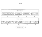
- FIG. 4 and FIG. 5 provide flow charts illustrating a method of producing a waterproof member according to an exemplary embodiment of the invention.
- a method of producing a waterproof member includes steps of (S1) injecting a first UV resin solution into a first mold, (S2) placing a polymer sheet onto the first UV resin solution, (S3) compressing the polymer sheet and the first UV resin solution to be closely adhered to each other, (S4) curing the first UV resin layer on the polymer sheet by irradiating UV into the first UV resin solution, (S5) injecting a second UV resin solution into a second mold, (S6) placing a polymer sheet having the first UV resin layer onto the second UV resin solution, (S7) compressing the polymer sheet and the second UV resin solution to be closely adhered to each other, and (S8) curing the second UV resin molding on the polymer sheet by irradiating UV into the second UV resin solution.
- the step (S1) and step (S5) may be performed simultaneously or sequentially.
- the first mold and the second mold may be shaped according to the shape of the device to which the waterproof member is to be applied, but not limited thereto.
- the waterproof member may be fabricated in a flat sheet-like shape and then cut and machined into a desired shape. In this manner, the fabrication cost of molds and raw material costs may be saved and the production process may be simplified.
- the waterproof member can be produced by modifying existing manufacturing equipment.
- the first UV resin solution and the second UV resin solution may be the same or different from each other.
- top and bottom resin layers are designed to have different restoring and compressive forces, different UV resin solutions may be used, or UV resin solution layers having different thicknesses may be used according to its desired use.
- step (S2) the polymer sheet is placed to cover the UV resin solution.
- step (S3) the compressive force and direction and the size of roller are determined according to the size and thickness of the waterproof member and detailed descriptions thereabout will not be given because they may be adjustably selected by one skilled in the art.
- step (S4) curing of UV resin can be appropriately selected and modified according to the UV resin solution used.
- the curing may be performed by irradiating a UV lamp of 700J to 1000J for 5 to 10 seconds.
- step (S6) a polymer sheet having the first UV resin molding is placed such that top and second moldings of the polymer sheet are symmetrical with each other.
- step (S7) the polymer sheet and the second UV resin solution are compressed to be adhered to each other.
- the first UV resin layer may be shaped by machining by shaping the flatly-shaped waterproof member, followed by cutting and machining.
- step (S8) the second UV resin layer is cured in the same condition as described in step (S4).
- the method of producing a waterproof member may further include the step (S9) of cutting and machining the waterproof member. That is to say, a flatly-shaped waterproof member may be produced in the desired shape without separately producing a mold according to the device using a waterproof member to then be subjected to machining through cutting and machining steps, thereby producing a waterproof member having a desired shape.
- the waterproof member having a desired shape can be produced simply by changing the program through, for example, NC (Numerical Control) machining, thereby easily producing the waterproof member having a more complex, smaller shape.
- a 140x60 mm shape was machined in a 220x200 mm mold to a depth of 0.5 mm in consideration of an NC machining width for a 125x47 shape and a UV resin solution (2004e commercially available from Mirae C&P, Korea) is injected into the mold.
- a 300 ⁇ m thick PC Sheet was placed to cover the UV resin solution and then compressed back and forth with a pressure of 2 kgf/cm 2 using a 250mm roller.
- a UV lamp of 900 J was irradiated onto the sheet for 10 seconds for curing, producing a top UV resin layer.
- the cured top UV resin layer was removed from the mold, followed by a second injection of the UV resin solution into the mold.
- the PC sheet having the UV resin layer was placed on the second UV resin solution then compressed, and the UV lamp was further irradiated for 10 seconds for curing, producing a bottom UV resin layer, thereby assembling a waterproof member having a sandwiched structure.
- the produced waterproof member was NC machined to seal a gap created between upper and lower cases of a cellular phone, thereby producing a ring-shaped waterproof member.
- Evaluation criteria of the waterproof member produced according to Example 1, including the moldability, production period, production cost, correcting convenience and correction cost of a mold, the work efficiency, and so on, are compared with those of the conventional waterproof ring (SILICON 40°, RUBBER PACK CASE, NOK Corporation), and the comparison results are summarized in Table 1.
- Table 1 Conventional waterproof ring Waterproof member of Example 1 Moldability Precision mold, not available in Korea Moldable in approximately 1 week Mold production period Approximately 7 weeks Approximately 1 week Mold production cost Approximately 80,000,000 (in Korean currency) Approximately 4,000,000 (in Korean currency) Mold correcting convenience Approximately 30 days Approximately 3 days Mold correction cost Approximately 3,000,000 (in Korean currency) Approximately 1,000,000 (in Korean currency) Operation efficiency Approximately 3 min for assembling Approximately 10 sec for assembling Production time required per piece Approximately 4 min/1piece Approximately 10 sec/1piece Raw material cost Approximately 1,200 (in Korean currency) Approximately 300 (in Korean currency)
- Example 2 As understood from Table 2, the waterproof member of Example 1 and the conventional waterproof ring were equal in view of the waterproofing level.
- Example 2 As understood from Table 2, the waterproof member of Example 1 and the conventional waterproof ring demonstrated similar waterproofing capabilities.
- a waterproof member includes a polymer sheet and a UV resin layer adhered to the polymer sheet.
- a method of producing a waterproof member includes injecting a first UV resin solution into a first resin molding, placing a polymer sheet onto the first UV resin solution, compressing the polymer sheet and the first UV resin solution to be closely adhered to each other, curing a first UV resin layer on the polymer sheet by irradiating UV into the first UV resin solution, injecting a second UV resin solution into a second resin molding, placing a polymer sheet having the first UV resin molding onto the second resin molding, compressing the polymer sheet and the second UV resin solution to be closely adhered to each other, and curing a second UV resin layer on the polymer sheet by irradiating UV into the second UV resin solution.
Landscapes
- Engineering & Computer Science (AREA)
- Mechanical Engineering (AREA)
- Manufacturing & Machinery (AREA)
- Casting Or Compression Moulding Of Plastics Or The Like (AREA)
- Telephone Set Structure (AREA)
- Coating Of Shaped Articles Made Of Macromolecular Substances (AREA)
- Laminated Bodies (AREA)
Abstract
A waterproof member includes a polymer sheet and a UV resin layer adhered to the polymer sheet. A method of producing a waterproof member includes injecting a first UV resin solution into a first resin molding, placing a polymer sheet onto the first UV resin solution, compressing the polymer sheet and the first UV resin solution to be closely adhered to each other, curing a first UV resin layer on the polymer sheet by irradiating UV into the first UV resin solution, injecting a second UV resin solution into a second resin molding, placing a polymer sheet having the first UV resin molding onto the second resin molding, compressing the polymer sheet and the second UV resin solution to be closely adhered to each other, and curing a second UV resin layer on the polymer sheet by irradiating UV into the second UV resin solution.
Description
- This application claims priority from and the benefit under 35 U.S.C. §119(a) of Korean Patent Application No.
10-2010-0122458, filed on December 3, 2010 - FIELD
- The present invention relates to a waterproof member and a method of producing the same. More particularly, to a waterproof member and a method of producing the member for protecting internal components of a mobile terminal from moisture damage.
- DISCUSSION OF THE BACKGROUND
- In general, electronic products, particularly mobile terminals, can be freely used regardless of location while a user moves. Owing to convenience in use, use of mobile communication terminals, such as mobile phones and personal digital assistants (PDAs) that are referred to as personal portable terminals, is gradually growing. However, since the mobile terminals are normally used while users are on the move, there may be an increased risk of being exposed to water or moisture. For example, mobile terminals may be at risk of being dropped into a pool of water, or getting wet by unexpected rain or spilled beverage. Electronic products, which are vulnerable to moisture, may be provided with a mechanism having waterproofing capacity. Accordingly, a variety of waterproof members have been developed. However, in existing waterproof members, as shown in
FIG. 1 , a gap between assembled products, that is, a gap between upper and lower cases in a cellular phone, is conventionally sealed with rubber or silicon. - In such a case, however, the conventional rubber or silicon may have difficulty in maintaining its shape (regularity), and as a result, it may be difficult to perform assembling work with the conventional rubber or silicon. Accordingly, the assembling of the conventional waterproof members may result in poor operation efficiency. In addition, rubber or silicon may be lengthened due to its ductility, which may result in inconsistent shape. Accordingly, the waterproof capacity may gradually decrease for these reasons with a prolonged use.
- Exemplary embodiments of the present invention provide a water proofing member and a method for producing the same.
- Additional features of the invention will be set forth in the description which follows, and in part will be apparent from the description, or may be learned by practice of the invention.
- Exemplary embodiments of the present invention provide a polymer sheet, and an ultraviolet (UV) resin layer adhered to a first surface and a second surface of the polymer sheet.
- Exemplary embodiments of the present invention provide a method for producing a waterproof member that including injecting a first ultraviolet (UV) resin solution into a first resin molding; placing a polymer sheet onto the first UV resin solution; compressing the polymer sheet and the first UV resin solution to be adhered to each other; and curing a first UV resin layer on the polymer sheet by irradiating UV into the first UV resin solution.
- Exemplary embodiments of the present invention provide a member to prevent liquid from entering into an area including a first material formed by ultraviolet (UV) irradiation; a second material; and a third material formed by UV irradiation, in which the first material and the third material sandwich the second material.
- Exemplary embodiments of the present invention provide a terminal including a waterproof member to block liquid from entry, in which the waterproof member includes a polymer sheet, and an ultraviolet (UV) resin layer adhered to a first surface and a second surface of the polymer sheet.
- It is to be understood that both foregoing general descriptions and the following detailed description are exemplary and explanatory and are intended to provide further explanation of the invention as claimed. Other features and aspects will be apparent from the following detailed description, the drawings, and the claims.
- The accompanying drawings, which are included to provide a further understanding of the invention and are incorporated in and constitute a part of this specification, illustrate embodiments of the invention, and together with the description serve to explain the principles of the invention.
-
FIG. 1 is a schematic cross-sectional view of a conventional waterproof member. -
FIG. 2 is a cross-sectional view of a waterproof member according to an exemplary embodiment of the invention. -
FIG. 3 is a front view of the waterproof member shown inFIG. 2 according to an exemplary embodiment of the invention. -
FIG. 4 is a flow chart illustrating a method of producing a waterproof member according to an exemplary embodiment of the invention. -
FIG. 5 is a flow chart illustrating a method of producing a waterproof member according to an exemplary embodiment of the invention. - The invention is described more fully hereinafter with references to the accompanying drawings, in which exemplary embodiments of the invention are shown. This invention may, however, be embodied in many different forms and should not be construed as limited to the embodiments set forth herein. Rather, these exemplary embodiments are provided so that this disclosure is thorough, and will fully convey the scope of the invention to those skilled in the art. It will be understood that when an element is referred to as being "adhered to" or "attached to" another element, it can be directly adhered or attached to the other element, or intervening elements may be present. Throughout the drawings and the detailed description, unless otherwise described, the same drawing reference numerals are understood to refer to the same elements, features, and structures. The relative size and depiction of these elements may be exaggerated for clarity, illustration, and convenience.
-
FIG. 1 is a schematic cross-sectional view of a conventional waterproof member. As shown inFIG. 1 , the conventional waterproof member includes a rubber or silicone to act as a seal against moisture. - Hereinafter, embodiments of the present invention will be described in detail with reference to the accompanying drawings.
-
FIG. 2 is a cross-sectional view of a waterproof member according to an exemplary embodiment of the invention. - As shown in
FIG. 2 , the waterproof member includes one or more layers of ultraviolet (UV) resin and a polymer sheet to provide protection against moisture. More specifically, the waterproof member includes a polymer sheet capable of maintaining regularity and materials having a compressive and restoring forces sandwiched on top and bottom of the polymer sheet. In addition, one or more layers of soft UV resin, which may exhibit compressive and restoring force, are provided on both sides of the polymer sheet. - While the waterproof member according to the exemplary embodiment of the invention includes a polymer sheet and soft UV resin layers assembled on top and bottom of the polymer sheet, the invention is not limited to such configuration or the number of resin layers and polymer sheets.
- In an example, the polymer sheet capable of maintaining regularity may be used in the water proof member. More specifically, a polymer sheet having high adhesiveness with respect to soft UV resin may be preferably used. For example, a PC (Polycarbonate) or PET (Polyethylene Terephthalate) sheet may be used as the polymer sheet, but not limited thereto.
- Further, a thickness of the polymer sheet may preferably be in a range of 150 to 300 µm. If the polymer sheet is too thin, it may be difficult to maintain regularity thereof. If the polymer sheet is too thick, the compressive strength thereof may be lowered, and may lower waterproofing efficiency.
- The soft UV resin used may be a resin that is commercially available or synthesized. In an example, the soft resins with a thickness of 300 µm to 500 µm may provide acceptable comprehensive strength. In addition to the raw material thereof, a curing agent may be added. In addition, the soft UV resin may be produced to further include functional additives, such as an anti-foaming agent, an extinction agent, or the like.
- A thickness of the soft UV resin layer is preferably in a range of 300 µm to 500 µm. If the UV resin layer is too thin, the compressive strength thereof may be lowered, thereby undesirably lowering waterproof efficiency. If the soft UV resin layer is too thick, the regularity thereof may deteriorate.
- A resin generally classified as a soft in view of the relative softness of UV resin may be used as the soft UV resin in the waterproof member. For example, a resin layer resulting from curing preferably has Shore hardness in a range of 40° to 60°. If the waterproof member has an excessively high hardness, deformation may occur in the course of producing the waterproof member. In addition, if an external force is applied, cracks may be generated and compression may not be performed properly. If the waterproof member has an excessively low hardness, the waterproof member may be lengthened or may have poor restoration capacity after a prolonged use, thus causing the waterproof member to be deformed due to an external force applied thereto.
- The waterproof member according to the present invention can be applied to assembled machines and electronic devices. For example, the waterproof member according to the present invention can be applied to a variety of devices that may benefit from waterproofing capabilities. Such devices may find difficulty in providing waterproofing due to a gap between assembled components, like a mobile communication terminals, such as PMP, PDA, cellular phones, and the like. The waterproof member sealing a gap created between upper and lower cases of a cellular phone as provided by the presently disclosed waterproof member may be shaped as connected rings, for example, as shown in
FIG. 3 . More specifically,FIG. 3 provides a front view of the waterproof member shown inFIG. 2 according to an exemplary embodiment of the invention. -
FIG. 4 andFIG. 5 provide flow charts illustrating a method of producing a waterproof member according to an exemplary embodiment of the invention. Referring toFIG. 4 andFIG. 5 , a method of producing a waterproof member includes steps of (S1) injecting a first UV resin solution into a first mold, (S2) placing a polymer sheet onto the first UV resin solution, (S3) compressing the polymer sheet and the first UV resin solution to be closely adhered to each other, (S4) curing the first UV resin layer on the polymer sheet by irradiating UV into the first UV resin solution, (S5) injecting a second UV resin solution into a second mold, (S6) placing a polymer sheet having the first UV resin layer onto the second UV resin solution, (S7) compressing the polymer sheet and the second UV resin solution to be closely adhered to each other, and (S8) curing the second UV resin molding on the polymer sheet by irradiating UV into the second UV resin solution. - In an example, the step (S1) and step (S5) may be performed simultaneously or sequentially. Also, in the step (S1) and step (S5), the first mold and the second mold may be shaped according to the shape of the device to which the waterproof member is to be applied, but not limited thereto. Alternatively, the waterproof member may be fabricated in a flat sheet-like shape and then cut and machined into a desired shape. In this manner, the fabrication cost of molds and raw material costs may be saved and the production process may be simplified. In addition, the waterproof member can be produced by modifying existing manufacturing equipment.
- The first UV resin solution and the second UV resin solution may be the same or different from each other.
- For example, if the top and bottom resin layers are designed to have different restoring and compressive forces, different UV resin solutions may be used, or UV resin solution layers having different thicknesses may be used according to its desired use.
- In step (S2), the polymer sheet is placed to cover the UV resin solution.
- In step (S3), the compressive force and direction and the size of roller are determined according to the size and thickness of the waterproof member and detailed descriptions thereabout will not be given because they may be adjustably selected by one skilled in the art.
- In step (S4), curing of UV resin can be appropriately selected and modified according to the UV resin solution used. For example, the curing may be performed by irradiating a UV lamp of 700J to 1000J for 5 to 10 seconds.
- In step (S6), a polymer sheet having the first UV resin molding is placed such that top and second moldings of the polymer sheet are symmetrical with each other.
- In step (S7), the polymer sheet and the second UV resin solution are compressed to be adhered to each other. In a case where compressing of the first UV resin layer may be difficult to achieve due to presence of a three-dimensional structure, the first UV resin layer may be shaped by machining by shaping the flatly-shaped waterproof member, followed by cutting and machining.
- In step (S8), the second UV resin layer is cured in the same condition as described in step (S4).
- In the illustrated embodiment of the present invention, the method of producing a waterproof member may further include the step (S9) of cutting and machining the waterproof member. That is to say, a flatly-shaped waterproof member may be produced in the desired shape without separately producing a mold according to the device using a waterproof member to then be subjected to machining through cutting and machining steps, thereby producing a waterproof member having a desired shape. The waterproof member having a desired shape can be produced simply by changing the program through, for example, NC (Numerical Control) machining, thereby easily producing the waterproof member having a more complex, smaller shape.
- Hereinafter, the present invention will be described in more detail through several embodiments. The following examples are given for purely illustrative and non-limiting purposes of the present invention.
- Example 1
- A 140x60 mm shape was machined in a 220x200 mm mold to a depth of 0.5 mm in consideration of an NC machining width for a 125x47 shape and a UV resin solution (2004e commercially available from Mirae C&P, Korea) is injected into the mold. A 300 µm thick PC Sheet was placed to cover the UV resin solution and then compressed back and forth with a pressure of 2 kgf/cm2 using a 250mm roller. A UV lamp of 900 J was irradiated onto the sheet for 10 seconds for curing, producing a top UV resin layer. The cured top UV resin layer was removed from the mold, followed by a second injection of the UV resin solution into the mold. The PC sheet having the UV resin layer was placed on the second UV resin solution then compressed, and the UV lamp was further irradiated for 10 seconds for curing, producing a bottom UV resin layer, thereby assembling a waterproof member having a sandwiched structure.
- The produced waterproof member was NC machined to seal a gap created between upper and lower cases of a cellular phone, thereby producing a ring-shaped waterproof member.
- Experimental Example 1
- Evaluation criteria of the waterproof member produced according to Example 1, including the moldability, production period, production cost, correcting convenience and correction cost of a mold, the work efficiency, and so on, are compared with those of the conventional waterproof ring (SILICON 40°, RUBBER PACK CASE, NOK Corporation), and the comparison results are summarized in Table 1.
-
Table 1 Conventional waterproof ring Waterproof member of Example 1 Moldability Precision mold, not available in Korea Moldable in approximately 1 week Mold production period Approximately 7 weeks Approximately 1 week Mold production cost Approximately 80,000,000 (in Korean currency)
Approximately 4,000,000 (in Korean currency)
Mold correcting convenience Approximately 30 days Approximately 3 days Mold correction cost Approximately 3,000,000 (in Korean currency)
Approximately 1,000,000 (in Korean currency)
Operation efficiency Approximately 3 min for assembling Approximately 10 sec for assembling Production time required per piece Approximately 4 min/1piece Approximately 10 sec/1piece Raw material cost Approximately 1,200 (in Korean currency)
Approximately 300 (in Korean currency)
- Experimental Example 2
- Cellular phones (PT001) employing the conventional waterproof ring and the waterproof member of Example 1 were submerged into a 1 m deep water basin for 30 minutes and taken out from the water basin. Then, the cellular phones were disassembled to confirm whether a paper indicator reacting to moisture or water was discolored or not. In an example, the paper indicator is a paper which changes color if it is exposed to moisture. The result of this experiment is summarized in Table 2.
- As understood from Table 2, the waterproof member of Example 1 and the conventional waterproof ring were equal in view of the waterproofing level.
-
Table 2 Type Conventional waterproof ring (SILICONE 40°) Waterproof member of Example 1 Medium (2000 series) Hard (3000 series) Air leak tester Displacement of 4 µm Displacement of 7 µm Displacement of 30 µm Fail IPX 7 grade TEST Submerged sheet was not discolored Submerged sheet was not discolored Submerged sheet was discolored Submerged sheet was discolored - * Remark:
- 1) Successful waterproofing levels of PT001 as measured using an air leak tester were 10 µm or less.
- 2)
IPX 7 grade test: It was confirmed whether cellular phones submerged to a depth of 1 m for 30 minutes (confirmed as 'OK' or 'Fail' by checking discoloration of the paper indicator). - As understood from Table 2, the waterproof member of Example 1 and the conventional waterproof ring demonstrated similar waterproofing capabilities.
- It will be apparent to those skilled in the art that various modifications and variations can be made in the present invention without departing from the spirit or scope of the invention. Thus, it is intended that the present invention cover the modifications and variations of this invention provided they come within the scope of the appended claims and their equivalents.
A waterproof member includes a polymer sheet and a UV resin layer adhered to the polymer sheet. A method of producing a waterproof member includes injecting a first UV resin solution into a first resin molding, placing a polymer sheet onto the first UV resin solution, compressing the polymer sheet and the first UV resin solution to be closely adhered to each other, curing a first UV resin layer on the polymer sheet by irradiating UV into the first UV resin solution, injecting a second UV resin solution into a second resin molding, placing a polymer sheet having the first UV resin molding onto the second resin molding, compressing the polymer sheet and the second UV resin solution to be closely adhered to each other, and curing a second UV resin layer on the polymer sheet by irradiating UV into the second UV resin solution.
Claims (15)
- A waterproof member, comprising:a polymer sheet; andan ultraviolet (UV) resin layer adhered to a first surface and a second surface of the polymer sheet.
- The waterproof member of claim 1, wherein the UV resin layer comprises a top resin layer adhered on the first surface of the polymer sheet, and a lower resin layer adhered to the second surface of the polymer sheet.
- The waterproof member of claim 1 or 2, wherein the polymer sheet is made of PC (Polycarbonate) or PET (Polyethylene Terephthalate).
- The waterproof member of any of claims 1 to 3, wherein the polymer sheet has a thickness of 150 µm to 300 µm.
- The waterproof member of any of claims 1 to 4, wherein the UV resin layer has a thickness of 300 µm to 500 µm and/or a Shore hardness of 40° to 60°.
- The waterproof member of any of claims 1 to 5, wherein the UV resin layer further comprises at least one of:• a UV resin and a curing agent,• an anti-foaming agent, and• an extinction agent.
- The waterproof member of any of claims 1 to 6, wherein the waterproof member is shaped as connected rings.
- A method for producing a waterproof member, comprising:injecting a first ultraviolet (UV) resin solution into a first resin molding;placing a polymer sheet onto the first UV resin solution;compressing the polymer sheet and the first UV resin solution to be adhered to each other; andcuring a first UV resin layer on the polymer sheet by irradiating UV into the first UV resin solution.
- The method of claim 8, further comprising:injecting a second UV resin solution into a second resin molding;placing a polymer sheet having the first UV resin molding onto the second resin molding;compressing the polymer sheet and the second UV resin solution to be adhered to each other; andcuring a second UV resin layer on the polymer sheet by irradiating UV into the second UV resin solution.
- The method of claim 9, further comprising cutting and machining the polymer sheet having the first UV resin layer and the second UV resin layer.
- The method of claim 9 or 10, wherein injecting the second UV resin solution is performed simultaneously with injecting the first UV resin solution.
- The method of any of claims 9 to 11, wherein curing the first UV resin layer and curing the second UV resin layer is performed by irradiating a UV lamp by a value of 700 J to 1000 J and/or for a duration between 5 to 10 seconds.
- A member to prevent liquid from entering into an area, the member comprising:a first material formed by ultraviolet (UV) irradiation;a second material; anda third material formed by UV irradiation;wherein the first material and the third material sandwich the second material.
- The member of claim 13, wherein the first material and the third material have different restoring and compressive forces from each other and/or different thicknesses from each other.
- A terminal, comprising:a waterproof member to block liquid from entry into the terminal, wherein the waterproof member comprises:a polymer sheet; andan ultraviolet (UV) resin layer adhered to a first surface and a second surface of the polymer sheet.
Applications Claiming Priority (1)
| Application Number | Priority Date | Filing Date | Title |
|---|---|---|---|
| KR1020100122458A KR20120061245A (en) | 2010-12-03 | 2010-12-03 | Waterproof member and Method of producing the same |
Publications (1)
| Publication Number | Publication Date |
|---|---|
| EP2460654A1 true EP2460654A1 (en) | 2012-06-06 |
Family
ID=45093523
Family Applications (1)
| Application Number | Title | Priority Date | Filing Date |
|---|---|---|---|
| EP20110191689 Withdrawn EP2460654A1 (en) | 2010-12-03 | 2011-12-02 | Waterproof member and method of producing the same |
Country Status (5)
| Country | Link |
|---|---|
| US (1) | US20120141782A1 (en) |
| EP (1) | EP2460654A1 (en) |
| JP (1) | JP2012116191A (en) |
| KR (1) | KR20120061245A (en) |
| CN (1) | CN102555378A (en) |
Citations (2)
| Publication number | Priority date | Publication date | Assignee | Title |
|---|---|---|---|---|
| WO2008007857A1 (en) * | 2006-07-10 | 2008-01-17 | Lg Chem, Ltd. | Melt-extrusion optical plastic sheet of improved dimension stability and liquid crystal device window including the same |
| EP2141015A2 (en) * | 2008-06-30 | 2010-01-06 | Nitto Denko Corporation | Gasket material |
Family Cites Families (25)
| Publication number | Priority date | Publication date | Assignee | Title |
|---|---|---|---|---|
| JPS60129469A (en) * | 1983-12-16 | 1985-07-10 | Ishikawa Gasket Kk | Manufacture of gasket |
| JPS63293044A (en) * | 1987-05-26 | 1988-11-30 | Nichias Corp | Manufacture of annular gasket |
| JPH03248341A (en) * | 1990-02-26 | 1991-11-06 | Nec Corp | Optical disk substrate |
| US5213893A (en) * | 1990-09-14 | 1993-05-25 | Nippon Shokubai Co., Ltd. | Waterproofing agent for cable |
| JP2929340B2 (en) * | 1991-09-20 | 1999-08-03 | 日本ラインツ株式会社 | gasket |
| US5380693A (en) * | 1993-04-02 | 1995-01-10 | Ricoh Company, Ltd. | Transparent thermosensitive recording medium |
| JPH06305066A (en) * | 1993-04-26 | 1994-11-01 | Dainippon Printing Co Ltd | Light directing film and manufacturing method thereof |
| JP3634592B2 (en) * | 1997-01-08 | 2005-03-30 | セイコーエプソン株式会社 | Bonding fixtures, electronic devices and watches |
| JP3894650B2 (en) * | 1998-02-23 | 2007-03-22 | 三郎 曽我 | Durable decorative body |
| US6770128B1 (en) * | 1999-04-13 | 2004-08-03 | Grace Gmbh & Co. Kg | Matting agent radiation for curing coatings |
| JP4429515B2 (en) * | 2000-03-09 | 2010-03-10 | 帝人株式会社 | Polymer resin laminate, method for producing the same, and molded article comprising the laminate |
| JP4518450B2 (en) * | 2000-12-14 | 2010-08-04 | 日東電工株式会社 | Photopolymerizable adhesive composition and adhesive sheet thereof |
| JP2002294182A (en) * | 2001-03-28 | 2002-10-09 | Okamoto Ind Inc | Waterproofing tape for building |
| EP1508423A3 (en) * | 2003-07-24 | 2005-04-27 | Fuji Photo Film Co., Ltd. | Process for producing an optical disc substrate |
| DE102004009437A1 (en) * | 2004-02-24 | 2005-09-15 | Basf Ag | Radiation curable composite layer plate or film |
| JP4021915B2 (en) * | 2005-11-25 | 2007-12-12 | 株式会社ブリヂストン | Photocurable liquid resin production method and photocurable liquid resin produced by the method |
| KR100815059B1 (en) * | 2006-08-11 | 2008-03-18 | 주식회사 엘지화학 | Waterproof sheet |
| KR100995509B1 (en) * | 2007-01-18 | 2010-11-19 | 주식회사 엘지화학 | Acrylic pressure-sensitive adhesive composition |
| JP2009151476A (en) * | 2007-12-19 | 2009-07-09 | Nof Corp | Surface material for pen input device and pen input device including the same |
| WO2009107537A1 (en) * | 2008-02-29 | 2009-09-03 | 株式会社カネカ | Curable composition |
| JP5227676B2 (en) * | 2008-06-20 | 2013-07-03 | 株式会社イノアックコーポレーション | Waterproof sealing material and manufacturing method thereof |
| JP5396951B2 (en) * | 2009-03-18 | 2014-01-22 | 三菱化学株式会社 | Active energy ray-curable composition and laminate |
| JP2010224113A (en) * | 2009-03-23 | 2010-10-07 | Jsr Corp | Lens film and backlight unit using the same |
| JP4906167B2 (en) * | 2009-03-25 | 2012-03-28 | 三菱樹脂株式会社 | Coating film |
| WO2010113605A1 (en) * | 2009-03-31 | 2010-10-07 | 株式会社 きもと | Surface protection film |
-
2010
- 2010-12-03 KR KR1020100122458A patent/KR20120061245A/en not_active Ceased
-
2011
- 2011-11-18 US US13/300,370 patent/US20120141782A1/en not_active Abandoned
- 2011-12-01 CN CN2011103929016A patent/CN102555378A/en active Pending
- 2011-12-02 EP EP20110191689 patent/EP2460654A1/en not_active Withdrawn
- 2011-12-02 JP JP2011264493A patent/JP2012116191A/en not_active Withdrawn
Patent Citations (2)
| Publication number | Priority date | Publication date | Assignee | Title |
|---|---|---|---|---|
| WO2008007857A1 (en) * | 2006-07-10 | 2008-01-17 | Lg Chem, Ltd. | Melt-extrusion optical plastic sheet of improved dimension stability and liquid crystal device window including the same |
| EP2141015A2 (en) * | 2008-06-30 | 2010-01-06 | Nitto Denko Corporation | Gasket material |
Also Published As
| Publication number | Publication date |
|---|---|
| CN102555378A (en) | 2012-07-11 |
| US20120141782A1 (en) | 2012-06-07 |
| JP2012116191A (en) | 2012-06-21 |
| KR20120061245A (en) | 2012-06-13 |
Similar Documents
| Publication | Publication Date | Title |
|---|---|---|
| KR200470939Y1 (en) | Flip type case for portable electronic device | |
| JP7771556B2 (en) | Films, films with release films, diaphragms, laminates, molded products and acoustic transducers | |
| CN107210236B (en) | The manufacturing method of film, its manufacturing method and the semiconductor element using the film | |
| EP3240304A1 (en) | Acoustic membrane | |
| CN101864807B (en) | Vibration-isolating rubber bearing for building and manufacturing method thereof | |
| WO2005079290A3 (en) | Hybrid contact lens system and method | |
| MXPA03006124A (en) | Plasticizer-containing polyvinylbutyrals, method for producing the same and the use thereof, especially for producing films for use in laminated safety glasses. | |
| US12200459B2 (en) | Vibrating diaphragm of sound-producing apparatus and sound-producing apparatus | |
| KR20050080733A (en) | Seal member and method for manufacturing the same | |
| US20140061070A1 (en) | Method for manufacturing a case for a portable electronic device, and case for a portable electronic device | |
| KR102373042B1 (en) | Manufacturing method of hyper soft neoprene foam rubber fabric and fabric manufactured by the method | |
| US20120141782A1 (en) | Waterproof member and method for producing the same | |
| KR102064325B1 (en) | Cross linked rubber foam sheet including polyvinylcloride, welded laminate and method of cross linked rubber foam sheet including polyvinylcloride | |
| KR101343415B1 (en) | Multi-layers polyurethane structures and method for menufacturing thereof | |
| CN111070531B (en) | A kind of preparation method of building seismic isolation rubber bearing and product thereof | |
| EP3360678B1 (en) | Real wood film and method of manufacturing injection-molded real wood product by using the same | |
| KR101944818B1 (en) | Adhesive Composition for Cell Pouch Film of Lithium Ion Cell and Method of Preparing The Same | |
| US20110318592A1 (en) | Molded article and method for making the same | |
| KR101726910B1 (en) | Adhesive sheet for encapsulating oled device and method for preparing the same | |
| JP2005047262A (en) | Manufacturing method of rubber member with base material and rubber member with base material | |
| KR101357424B1 (en) | Combi screen mask | |
| JP7779041B2 (en) | Films, films with release films, diaphragms, laminates, molded products and acoustic transducers | |
| JP7771555B2 (en) | Film for acoustic components, film for acoustic components with release film, acoustic components, laminate and acoustic transducer | |
| JP3903244B2 (en) | Method for producing sheet-like elastic body | |
| CN111864374B (en) | 5G base station millimeter wave antenna housing and manufacturing method thereof |
Legal Events
| Date | Code | Title | Description |
|---|---|---|---|
| PUAI | Public reference made under article 153(3) epc to a published international application that has entered the european phase |
Free format text: ORIGINAL CODE: 0009012 |
|
| AK | Designated contracting states |
Kind code of ref document: A1 Designated state(s): AL AT BE BG CH CY CZ DE DK EE ES FI FR GB GR HR HU IE IS IT LI LT LU LV MC MK MT NL NO PL PT RO RS SE SI SK SM TR |
|
| AX | Request for extension of the european patent |
Extension state: BA ME |
|
| STAA | Information on the status of an ep patent application or granted ep patent |
Free format text: STATUS: THE APPLICATION IS DEEMED TO BE WITHDRAWN |
|
| 18D | Application deemed to be withdrawn |
Effective date: 20121207 |