EP2460638A2 - Method for stretch blowing and stretch blowing machine - Google Patents
Method for stretch blowing and stretch blowing machine Download PDFInfo
- Publication number
- EP2460638A2 EP2460638A2 EP11189551A EP11189551A EP2460638A2 EP 2460638 A2 EP2460638 A2 EP 2460638A2 EP 11189551 A EP11189551 A EP 11189551A EP 11189551 A EP11189551 A EP 11189551A EP 2460638 A2 EP2460638 A2 EP 2460638A2
- Authority
- EP
- European Patent Office
- Prior art keywords
- force
- stretching
- reduced
- controlled
- time
- Prior art date
- Legal status (The legal status is an assumption and is not a legal conclusion. Google has not performed a legal analysis and makes no representation as to the accuracy of the status listed.)
- Granted
Links
- 238000000034 method Methods 0.000 title claims abstract description 52
- 238000007664 blowing Methods 0.000 title claims abstract description 29
- 230000008569 process Effects 0.000 claims description 24
- 230000009467 reduction Effects 0.000 claims description 24
- 238000000071 blow moulding Methods 0.000 claims description 17
- 230000008878 coupling Effects 0.000 description 5
- 238000010168 coupling process Methods 0.000 description 5
- 238000005859 coupling reaction Methods 0.000 description 5
- 230000000875 corresponding effect Effects 0.000 description 4
- 238000000465 moulding Methods 0.000 description 3
- 238000000418 atomic force spectrum Methods 0.000 description 2
- 238000004891 communication Methods 0.000 description 2
- 238000013461 design Methods 0.000 description 2
- 238000006073 displacement reaction Methods 0.000 description 2
- 239000000463 material Substances 0.000 description 2
- 230000007246 mechanism Effects 0.000 description 2
- 238000013459 approach Methods 0.000 description 1
- 239000000969 carrier Substances 0.000 description 1
- 230000001276 controlling effect Effects 0.000 description 1
- 238000001816 cooling Methods 0.000 description 1
- 230000002596 correlated effect Effects 0.000 description 1
- 230000001419 dependent effect Effects 0.000 description 1
- 238000001514 detection method Methods 0.000 description 1
- 238000011161 development Methods 0.000 description 1
- 230000006870 function Effects 0.000 description 1
- 239000000314 lubricant Substances 0.000 description 1
- 238000005461 lubrication Methods 0.000 description 1
- 238000005259 measurement Methods 0.000 description 1
- 238000003825 pressing Methods 0.000 description 1
- 230000000750 progressive effect Effects 0.000 description 1
- 230000004044 response Effects 0.000 description 1
- 238000012546 transfer Methods 0.000 description 1
Images

Classifications
-
- B—PERFORMING OPERATIONS; TRANSPORTING
- B29—WORKING OF PLASTICS; WORKING OF SUBSTANCES IN A PLASTIC STATE IN GENERAL
- B29C—SHAPING OR JOINING OF PLASTICS; SHAPING OF MATERIAL IN A PLASTIC STATE, NOT OTHERWISE PROVIDED FOR; AFTER-TREATMENT OF THE SHAPED PRODUCTS, e.g. REPAIRING
- B29C49/00—Blow-moulding, i.e. blowing a preform or parison to a desired shape within a mould; Apparatus therefor
- B29C49/08—Biaxial stretching during blow-moulding
- B29C49/10—Biaxial stretching during blow-moulding using mechanical means for prestretching
- B29C49/12—Stretching rods
-
- B—PERFORMING OPERATIONS; TRANSPORTING
- B29—WORKING OF PLASTICS; WORKING OF SUBSTANCES IN A PLASTIC STATE IN GENERAL
- B29C—SHAPING OR JOINING OF PLASTICS; SHAPING OF MATERIAL IN A PLASTIC STATE, NOT OTHERWISE PROVIDED FOR; AFTER-TREATMENT OF THE SHAPED PRODUCTS, e.g. REPAIRING
- B29C49/00—Blow-moulding, i.e. blowing a preform or parison to a desired shape within a mould; Apparatus therefor
- B29C49/02—Combined blow-moulding and manufacture of the preform or the parison
- B29C49/06—Injection blow-moulding
-
- B—PERFORMING OPERATIONS; TRANSPORTING
- B29—WORKING OF PLASTICS; WORKING OF SUBSTANCES IN A PLASTIC STATE IN GENERAL
- B29C—SHAPING OR JOINING OF PLASTICS; SHAPING OF MATERIAL IN A PLASTIC STATE, NOT OTHERWISE PROVIDED FOR; AFTER-TREATMENT OF THE SHAPED PRODUCTS, e.g. REPAIRING
- B29C49/00—Blow-moulding, i.e. blowing a preform or parison to a desired shape within a mould; Apparatus therefor
- B29C49/42—Component parts, details or accessories; Auxiliary operations
- B29C49/78—Measuring, controlling or regulating
-
- B—PERFORMING OPERATIONS; TRANSPORTING
- B29—WORKING OF PLASTICS; WORKING OF SUBSTANCES IN A PLASTIC STATE IN GENERAL
- B29C—SHAPING OR JOINING OF PLASTICS; SHAPING OF MATERIAL IN A PLASTIC STATE, NOT OTHERWISE PROVIDED FOR; AFTER-TREATMENT OF THE SHAPED PRODUCTS, e.g. REPAIRING
- B29C49/00—Blow-moulding, i.e. blowing a preform or parison to a desired shape within a mould; Apparatus therefor
- B29C49/02—Combined blow-moulding and manufacture of the preform or the parison
- B29C2049/023—Combined blow-moulding and manufacture of the preform or the parison using inherent heat of the preform, i.e. 1 step blow moulding
-
- B—PERFORMING OPERATIONS; TRANSPORTING
- B29—WORKING OF PLASTICS; WORKING OF SUBSTANCES IN A PLASTIC STATE IN GENERAL
- B29C—SHAPING OR JOINING OF PLASTICS; SHAPING OF MATERIAL IN A PLASTIC STATE, NOT OTHERWISE PROVIDED FOR; AFTER-TREATMENT OF THE SHAPED PRODUCTS, e.g. REPAIRING
- B29C49/00—Blow-moulding, i.e. blowing a preform or parison to a desired shape within a mould; Apparatus therefor
- B29C49/42—Component parts, details or accessories; Auxiliary operations
- B29C49/78—Measuring, controlling or regulating
- B29C2049/7879—Stretching, e.g. stretch rod
-
- B—PERFORMING OPERATIONS; TRANSPORTING
- B29—WORKING OF PLASTICS; WORKING OF SUBSTANCES IN A PLASTIC STATE IN GENERAL
- B29C—SHAPING OR JOINING OF PLASTICS; SHAPING OF MATERIAL IN A PLASTIC STATE, NOT OTHERWISE PROVIDED FOR; AFTER-TREATMENT OF THE SHAPED PRODUCTS, e.g. REPAIRING
- B29C49/00—Blow-moulding, i.e. blowing a preform or parison to a desired shape within a mould; Apparatus therefor
- B29C49/08—Biaxial stretching during blow-moulding
- B29C49/10—Biaxial stretching during blow-moulding using mechanical means for prestretching
- B29C49/122—Drive means therefor
- B29C49/123—Electric drives, e.g. linear motors
Definitions
- the invention relates to a method according to the preamble of patent claim 1 and to a stretch blow molding machine according to the preamble of patent claim 14.
- each stretching operation by an electric servomotor, z. B. a linear motor, controlled by the electronic programmable controller.
- a method is carried out in which the transmitted force from the servo motor to the stretch rod is variable z. B. to avoid damage to the mold cavity floor or Preformêts, in a control loop, wherein the force on the motor current and a donor position automatically results.
- the control unit predetermined force curves are controlled.
- a known stretch blow molding machine is a rigid stretching system on the stretch rod, an electric servomotor, z. As a linear motor, and provided a mechanical coupling.
- the control unit contains a controller for force-controlled stretching of the preform.
- the force transmitted to the stretching rod by the servomotor is measured by detecting the motor current and varied over the stretching path.
- the position of the stretch rod is determined in each case via encoders on the motor. Via the control unit predetermined force / displacement or force / time profiles are processed.
- the lower end of the stretch rod may press into the preform bottom to prevent the preform bottom from drifting away (off-center protection), otherwise resulting in uneven material thickness around the circumference of the container could.
- This so-called overpressure is easily controllable in pneumatic stretching rod drive systems, since the pneumatic cylinder goes to the stop and a pneumatic drive system is not rigid.
- stretch rod drive systems with an electric servomotor are rigid systems, wherein with each stretching operation there is a risk that the servomotor will try to approach a setpoint position with maximum force, but can not reach it, and is therefore thermally overloaded.
- the invention has for its object to provide a method of the type mentioned above and a suitable for performing the method stretch blow molding, with which the risk of thermal overloading of the electric servo motor is minimized or excluded.
- Part of the task is also, for example, in critical container shapes, despite minimizing or excluding thermal overloading of the electric servomotor, to achieve off center protection.
- the sequence of each stretching operation can be determined either fixedly or variably via the correspondingly designed input and display section in such a way that during a force control of the stretching bar adjustment the force transmitted by the servomotor to the stretching bar is reduced in a predetermined manner in the region of the end of the stretching process is, preferably after one or a predetermined time, to limit the thermal load of the servo motor and its servo to an allowable level, which minimizes or completely excludes the risk of thermal overload.
- the transmitted force is controlled controlled against a maximum force.
- the maximum force may be the maximum nominal force of the servomotor, or a force below the maximum nominal force, which, however, is generally greater than the residual force acting on the stretch rod after the force reduction.
- the force in the final phase of the stretching operation is reduced a predetermined period of time before the contact of the preform bottom with the mold cavity bottom and kept at least reduced over this time and kept to contact.
- the reduced force can also be maintained after the contact for a predetermined period of time, until the molding process of the container is completed or largely completed, and before the stretch rod is retracted again.
- the force at the end of the stretching process is reduced relatively precisely with the occurrence of the contact and then kept reduced over a predetermined period of time. Until contact, the stretch rod is driven with high force to ensure an optimally short cycle time. The power reduction will be reduced but only with completion of the entire stretching process.
- the force is reduced even after completion of the stretching process and only a predetermined waiting time after contact, and then kept reduced over a predetermined period of time.
- the waiting time is set so that a thermal overload of the servomotor or the servo inverter does not occur.
- the force is reduced by a fixed value, for example to a fixed percentage of the maximum force.
- the force is reduced by a variable value that is adapted to the respective process conditions and / or material parameters and / or container shape and the like.
- corresponding rotational angle ranges of a blow-molded blowing wheel are used in the force control, wherein the rotation angle of the blowing wheel is tapped via appropriate encoders and transmitted to the control unit.
- the force is expediently reduced to a residual force controlled with regard to thermal overload protection, at least of the servomotor.
- the time duration or waiting time with regard to a thermal overload protection is set. It may be expedient if the force is reduced only to a residual force controlled with respect to an off-center protection of the preform floor, and / or the time period or waiting time is set accordingly. Thus, for example, with a higher residual force, the time duration is set shorter, and vice versa with a lower residual force, the time duration is set longer.
- the force reduction can also be automatically calculated and controlled taking into account the current Servomotorbelastung, z. B. via a routine of the control unit or at least one servo inverter, z. B. by tracking a trend to a thermal limit load, and counteracted before reaching the limit load with the power reduction.
- the Force reduction can also be done here by a fixed value, or z. B. depending on the development of the trend (creeping or progressive) are variably controlled. The same applies to a set then waiting time and / or time duration.
- the stretching process is at least predominantly force-controlled, d. H. at least in the final phase.
- the stretching operation can be controlled away in an initial phase to achieve a short cycle time, and force controlled only in the final phase or at the end of the stretching operation, wherein, preferably, after switching from the path control to the force control, a fixed or variable waiting time is taken into account can until the force is reduced.
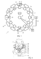
- Fig. 1 shows a stretch blow molding machine 1 for stretch blow molding of containers, in particular bottles of preforms.
- the stretch blow molding machine 1 here is a rotary machine with a blowing wheel 2 carrying blowing stations 4 on the one side, which represents a part 1a rotating in relation to a stationary part 1b.
- the concept according to the invention can also be used without restriction for stretch blow molding machines in which the blowing stations or a blowing station are or are arranged stationary (not shown).
- each control unit 20 is arranged at least for a blowing station 4 on the blowing wheel 2.
- the power supply of each control unit 20 is z. B. via connecting lines 11 and a rotary feedthrough 6, z.
- Each blowing station 4 comprises a stretch rod drive system A having an electric servomotor 16 and a servo inverter (not shown) and a valve section 12 optionally having a plurality of valves for controlling the supply of blown air in the stretch blown process on.
- at least one sensor 22 as encoder can be in communication with the respective control unit 20.
- an electronic timer 24 is provided, which can initiate a power stroke, for example, in response to a start signal, or can run times set for certain process phases.
- At least one sensor 30 may be provided as a position sensor for detecting an angular position during the rotation of the blowing wheel 2.
- These electronic components are connected, for example, to the respective control unit 20, or to a preferably programmable, electronic and central control unit 40 in the stationary part 1b, which communicates with the sensor 30 via an indicated connection 32, for example.
- a communication link 13 may be provided for transmitting a start signal to the respective control unit 20.
- a memory and / or input and / or display section 18 may be provided to store, read out, communicate, and the like.
- Each control unit 20 communicates via a connection 21 with the blowing station 4 or the stretching rod drive system A or the electric motor 16 for electric stretching.
- the input and / or display section 18 could alternatively or additionally be assigned to the central control unit 40.
- the respective input and / or display section 18 may, for. B. on the control unit 40 in the stationary part 1b, at least a portion 18a, 18b, z.
- a keyboard or a touch screen for entering or setting a z.
- the stretching force reduction (eg its extent or the residual force) and / or the duration or waiting time can be determined and taken into account automatically and / or additively by the control unit 20 or 40 or a servo converter provided there.
- the servo inverter often models internal servomotor models that are fed with operating parameters of the servomotor 16 such as motor current, temperature, etc., so that the current percentage motor load can be calculated. If the calculation exceeds a As soon as the thermal limit load has been detected, the servo inverter switches off as a precaution.
- This routine of the servo controller or the control unit 20, 40 can be used favorably to follow a trend to reach the thermal limit load and to reduce the stretching force in good time before reaching the thermal limit load, and possibly the corresponding thermal overload protection period and / or waiting time adjust.
- the electric servomotor 16 could be combined (not shown) with a force accumulator or pneumatic cylinder that assists or intervenes in each stretching operation, and which, if appropriate, is also controlled by the control unit 20.
- the control unit 20 can be used universally in various stretch blow molding machines and is optionally equipped with hardware and software technology to selectively control the respective blowing station 4 regardless of the type of stretch rod drive system A. Further, the control unit 20 may also control the pressurization in the stretch blown process and / or the required adjustments of a tuyere and other components bypassing the blowing pressure. Also, a central lubrication Z may be provided on the blowing wheel 2, the mechanical components on the blowing wheel 2, z. B. metering, supplied with lubricant.
- FIG. 2 to 4 are mutually associated views of an embodiment of a blowing station 4 with a stretch rod drive system A, although only main components are shown.
- a bearing block 3 mounted on the blowing wheel 2 above a split blow mold 26 (not shown in detail) carries the electric servomotor 16 and the control unit 20 embodied here as a rotary motor.
- the servo motor 16 and the control unit 20 can have a cooling body 5 on the head end of the bearing block 3 installed, the ( Fig. 4 ) is formed over a considerable part of its length as a U-profile.
- a stop 7 may be provided for a coupled to a stretching rod 15 Reckschlitten 14.
- the stopper 7 is, preferably, adjustable and / or cushioned.
- the stretch rod 15 is fixed via a releasable coupling 17 in the drawing carriage 14 and extends parallel to the bearing block 3 down to the blow mold 26, at the position of a preform P is shown, from the superposition of a stretching operation and a blowing process, a container with the shape the mold cavity of the blow mold 26 is formed.
- the stretch rod 15 passes through a slidably guided Blasschlitten 9, with which a tuyere 8 is connected, which is raised relative to the blow mold 26 and lowered to the seal, for example, on the mouth of a preform P used.
- the blow mold 26 has (not shown), for example, two mold halves and a mold cavity floor FB ( Fig. 4 ), wherein at least the mold halves are arranged in carriers, which can be moved by a mechanism, not shown, to open and close the blow mold 26 and to lock in the closed state and after introduction of the preform P.
- the tuyere 8 is placed on the Preformmündung B before the pressurization is carried out via the valve section 12, for example to perform a Vorblasphase lower pressure level and then a Fertigblasphase high pressure level, superimposed with the stretching operation by the stretch rod 15th , which is inserted into the blow mold 26 until at the end of the stretching process the preform bottom B is at least brought into contact or even overpressed with the mold cavity floor FB.
- the overpressing provides off center protection against lateral drift of the preform bottom B during the blow molding process.
- At least one drive rod 19 extends from the stretch carriage 16 to the blast carriage 9.
- the drive rod 19 can be coupled in a drive coupling 23 with the stretch carriage 14 in its return stroke direction of the stretch rod 15, for example to lift the blow carriage 9 or the stretch carriage 14 in relation to the then mechanically blocked Blasschlitten halt.
- the servo motor 16 is connected to the drawing carriage 14 via a threaded spindle 31, which is arranged in the interior of the U-profile 27 and may also be supported there.
- the stretching carriage 14 engages around the U-profile 27 and extends with a coupling 29 into the interior of the U-profile 27 and also in a linear guide 28 arranged there.
- the stretching rod 15 can be exchanged via the releasable coupling 17 from the drawing carriage 14.
- Fig. 4 indicates a jib 10 (see also FIGS. 2 and 3 ) on Blasschlitten 9.
- This lifting member 10 is, for example, a driving roller which cooperates with a not shown catching curve to lift the blast carriage 9, for example to vent the finished container in the tuyere 26, if an exhaust valve to a muffler 25 on the valve section 12 should not function properly ,
- the movement of the blow carriage is controlled by a cam control, not shown, or alternatively by a servomotor, and z. B. in time or path-dependent assignment to the mechanism that controls the locking phase of the blow mold 26.
- the control unit 20 controls during the stretching operation a precisely predetermined movement sequence of the stretching rod adjustment, so that the free end of the valve section 12 passing through the stretching rod 15 certain positions on and passes, for example, a first position in which the free end of the Stretching bar 15 the preform B of the not yet stretched preform P is approximated to about 1.0 mm, or the preform B already contacted, or even deeper position in the preform P is something vorgereckt. Thereafter, the stretch rod 15 is brought to an end position at the cavity bottom FB, but without touching the mold cavity floor FB. The stretch rod 15 can be moved away and / or force-controlled, wherein even during a working cycle of a displacement control can be switched to a force control, and vice versa. Also, the speed of the stretch rod without reversal during a stretching operation, for. B. at least twice, before after or shortly before completion of the molding of the container, the stretch rod 15 moves back again.
- the servomotor 16 may be a linear motor, preferably a linear motor of a tubular design or a flat design, and with its rotor form a direct drive of the stretch rod 15 (not shown).
- the electric servomotor 16 could be associated with a force storage device, for.
- a spring or a pneumatic cylinder that assists the servo motor 16 and / or generates predetermined force curves or absorbs or compensates forces, for example, the container produced by pressure at not yet vented blow mold 26 apply the stretch rod 15 in the return direction.
- the servomotor 16 could, as a rotary motor D, the rotational movement via a cable chain or a toothed belt, z. B. in an endless loop, on the stretch carriage 17 and the stretch rod 15 is transmitted (not shown).
- the stretching process is controlled in the electrical stretching of the preform P by means of the servo motor 16 so that the stretch rod 15 z. B. at the latest at the beginning of the locking phase or during the locking phase of the blow mold 26 is introduced, possibly even before the beginning of the locking phase, for example, when a not shown transfer to the preform P still open blow mold 26 moves in the same way as the blow mold 26th
- the stretching rod 15 is initially adjusted to approximately 1.0 mm towards the preform bottom B or even in contact therewith before the blowing nozzle 8 is sealingly placed on the preform opening 8 and the pre-blowing phase is introduced.
- the stretch rod 15 may be even further introduced by then, and have already begun to advance the preform P when the tuyere 8 touches down.
- the stretch rod 15 is still close in the Vorblasphase in which the container shape is blown to a predominant percentage the mold cavity bottom FB further adjusted until the preform B has at least contact with the mold cavity floor FB, wherein in the subsequent or superimposed Fertigblasphase with even higher blowing pressure, the stretch rod 15 continues to exert force and even a Nach conciseprints or overpressure of the preform B performs.
- the stretching bar adjustment is either controlled or force controlled by the control unit 20, and optionally correlated with the blast pressure control, wherein, as mentioned, during a stretching operation between a path control and a force control can be switched and different speeds can be controlled in different stretching phases.
- the positions of the stretch rod 15 during the stretching operation are set by the control unit 20, as well as the speed, which can be conveniently changed twice. Corresponding specifications are determined either by a preceding calibration process for obtaining parameter values for the control unit 20 and / or by inputting such parameter values, depending on the respective preform and / or container type.
- the respective position of the stretch rod 15 or the transmitted force are at least the determined stretching phases in the control unit 20 via corresponding signals and / or current values of the servomotor 16 can be determined, since the stretch rod drive system A is rigid.
- At least one frequency converter or servo converter is assigned to the servomotor 16, from which the servomotor 16 receives the supply voltage (eg approximately 600 to 900 V).
- the force transmitted to the stretch rod 15 by the servomotor 16 is reduced with respect to a maximum force (the maximum nominal force or a predetermined maximum force of the servo motor 16) in association with the final phase of the stretching operation, wherein expediently also a time duration or a waiting time is taken into account, and urgently as thermal overload protection for the servo motor 16 and its servo inverter.
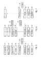
- the force reduction is controlled as needed so that either overpressing or pressing the Preformêts B as Offcenter protection is done or omitted. This is based on the Fig. 5 to 7 explained.
- Fig. 5 illustrates as a flow chart the flow of a stretching operation, in which initially carried out a path control and then switched to a force control.
- the locking phase of the blow mold 26 is completed.
- the stretching operation begins, as stated with a travel control 35, until at 36 the preform bottom B comes into contact with the mold cavity bottom FB.
- a force reduction ie, the transmitted from the servo motor 16 to the stretch rod 15 is compared to the maximum force to a reduced residual force reduced.
- a force reduction ie, the transmitted from the servo motor 16 to the stretch rod 15 is compared to the maximum force to a reduced residual force reduced.
- a predetermined waiting time at 39 may be set which is such that no thermal overload on the servomotor 16 can occur during this time.
- the force reduction or the residual force is maintained for a predetermined period of time 41, for example, until shortly before completion of the molding of the container, before at 42, the stretch rod 15 begins to go back again.
- the stretch rod 15 is adjusted from the beginning of the stretching operation at 34 with force control at 43 until 36 contact between the preform B and the mold cavity floor FB is formed.
- the force reduction is initiated at 38, which is then maintained at 41 for the predetermined period of time before the stretch rod begins its return motion at 42.
- the force control may not be active from the beginning 34 of the stretching operation, but it may be switched from the path control to the force control until the contact at 36, as indicated at 43 '.
- a waiting time at 39 may be set between the contact at 36 and the force reduction at 38.
- the process variants of Fig. 5, 6, 7 are not to be construed as limiting, but can be combined with each other.
- the force reduction can be controlled with a fixed force value, or the force value of the force reduction is individually varied.
- the wait time and / or duration may correspond to a first time, or may be varied as needed. Thereafter, alternatively, the waiting time and / or the time duration can be taken into account as a rotation angle range of a full revolution of the blowing wheel, so that the signals, for example, of the timer 24 in FIG Fig. 1 and / or the sensor 30 can be processed.
- the residual force can also be varied as needed after the force has been reduced.
Landscapes
- Engineering & Computer Science (AREA)
- Manufacturing & Machinery (AREA)
- Mechanical Engineering (AREA)
- Blow-Moulding Or Thermoforming Of Plastics Or The Like (AREA)
Abstract
Description
Die Erfindung betrifft ein Verfahren gemäß Oberbegriff des Patentanspruchs 1 sowie eine Streckblasmaschine gemäß Oberbegriff des Patentanspruchs 14.The invention relates to a method according to the preamble of
Bei einer aus
Bei einer aus
Nach Abschluss des Reckvorganges, d. h., sobald der Preform in seiner Länge komplett gereckt ist, kann das untere Ende der Reckstange in den Preformboden drücken, um ein Wegdriften des Preformbodens zur Seite zu verhindern (Offcenter-Schutz), was sonst in ungleichmäßiger Materialdicke über den Umfang des Behälters resultieren könnte. Dieses sogenannte Überdrücken ist bei pneumatischen Reckstangen-Antriebssystemen problemlos steuerbar, da der Pneumatikzylinder auf Anschlag geht und ein pneumatisches Antriebssystem nicht starr ist. Hingegen sind Reckstangen-Antriebssysteme mit einem elektrischen Servomotor starre Systeme, wobei bei jedem Reckvorgang die Gefahr auftritt, dass der Servomotor versucht, eine Sollposition mit maximaler Kraft anzufahren, diese aber nicht erreichen kann, und deshalb thermisch überlastet wird.After completion of the stretching process, d. that is, once the preform is fully stretched in length, the lower end of the stretch rod may press into the preform bottom to prevent the preform bottom from drifting away (off-center protection), otherwise resulting in uneven material thickness around the circumference of the container could. This so-called overpressure is easily controllable in pneumatic stretching rod drive systems, since the pneumatic cylinder goes to the stop and a pneumatic drive system is not rigid. By contrast, stretch rod drive systems with an electric servomotor are rigid systems, wherein with each stretching operation there is a risk that the servomotor will try to approach a setpoint position with maximum force, but can not reach it, and is therefore thermally overloaded.
Der Erfindung liegt die Aufgabe zugrunde, ein Verfahren der eingangs genannten Art sowie eine zum Durchführen des Verfahrens geeignete Streckblasmaschine anzugeben, mit denen die Gefahr einer thermischen Überlastung des elektrischen Servomotors minimiert oder ausgeschlossen wird. Teil der Aufgabe ist es ferner, beispielsweise bei kritischen Behälterformen, trotz Minimierens oder Ausschließens einer thermischen Überlastung des elektrischen Servomotors einen Offcenter-Schutz zu erzielen.The invention has for its object to provide a method of the type mentioned above and a suitable for performing the method stretch blow molding, with which the risk of thermal overloading of the electric servo motor is minimized or excluded. Part of the task is also, for example, in critical container shapes, despite minimizing or excluding thermal overloading of the electric servomotor, to achieve off center protection.
Die gestellte Aufgabe wird verfahrensgemäß mit den Merkmalen des Patentanspruchs 1 und mit einer Streckblasmaschine mit den Merkmalen des Patentanspruchs 14 gelöst.The stated object is achieved according to the method with the features of
Verfahrensgemäß wird trotz des starren Antriebssystems mit dem elektrischen Servomotor bei der Kraftsteuerung die vom Servomotor auf die Reckstange übertragene Kraft im Bereich des Endes des Reckvorgangs gezielt reduziert, so dass entweder gar kein Überdrücken oder nur ein gerade den Offcenter-Schutz sicherstellendes Überdrücken des Preformbodens erfolgt. Jedoch wird die Gefahr einer thermischen Überlastung des Servomotors minimiert oder ausgeschlossen, da der Servomotor nicht mit Maximalkraft versucht, eine Sollposition anzufahren, die er nicht erreichen kann, sondern mit der reduzierten Kraft und, vorzugsweise über eine begrenzte Dauer.According to the method, in spite of the rigid drive system with the electric servomotor in the force control transmitted by the servo motor on the stretch rod force in the range of the end of the stretching operation is deliberately reduced, so that either no overpressing or just the offcenter protection sicherstellendes overpressing the preform. However, the risk of thermal overload on the servomotor is minimized or eliminated because the servomotor does not attempt to travel to a desired position with maximum force, which it can not reach, but with the reduced force and, preferably, for a limited duration.
In der Streckblasmaschine lässt sich über die entsprechend konzipierte Eingabe- und Anzeigesektion der Ablauf jedes Reckvorgangs entweder mit festen Werten oder variabel so festlegen, dass bei einer Kraftsteuerung der Reckstangenverstellung die vom Servomotor auf die Reckstange übertragene Kraft im Bereich des Endes des Reckvorgangs auf vorbestimmte Weise reduziert wird, vorzugsweise nach einer oder über eine vorbestimmte Zeit, um die thermische Belastung des Servomotors und dessen Servoumrichters auf ein zulässiges Maß zu begrenzen, das die Gefahr einer thermischen Überlastung zumindest minimiert oder vollständig ausschließt.In the stretch blow molding machine, the sequence of each stretching operation can be determined either fixedly or variably via the correspondingly designed input and display section in such a way that during a force control of the stretching bar adjustment the force transmitted by the servomotor to the stretching bar is reduced in a predetermined manner in the region of the end of the stretching process is, preferably after one or a predetermined time, to limit the thermal load of the servo motor and its servo to an allowable level, which minimizes or completely excludes the risk of thermal overload.
Die übertragene Kraft wird gegenüber einer Maximalkraft gesteuert reduziert. Die Maximalkraft kann die maximale Nennkraft des Servomotors sein, oder eine unterhalb der maximalen Nennkraft liegende Kraft, die jedoch im Regelfall größer ist als die nach der Kraftreduktion an der Reckstange wirkende Restkraft.The transmitted force is controlled controlled against a maximum force. The maximum force may be the maximum nominal force of the servomotor, or a force below the maximum nominal force, which, however, is generally greater than the residual force acting on the stretch rod after the force reduction.
Bei einer zweckmäßigen Verfahrensvariante wird die Kraft in der Endphase des Reckvorgangs eine vorbestimmte Zeitdauer vor dem Kontakt des Preformbodens mit dem Formhohlraumboden reduziert und zumindest über diese Zeitdauer und bis zum Kontakt reduziert gehalten steuert. Vorzugsweise kann die reduzierte Kraft auch anschließend an den Kontakt noch über eine vorbestimmte Zeitdauer gehalten werden, bis der Ausformprozess des Behälters abgeschlossen oder weitestgehend abgeschlossen ist, und ehe die Reckstange wieder zurückgezogen wird.In an expedient variant of the method, the force in the final phase of the stretching operation is reduced a predetermined period of time before the contact of the preform bottom with the mold cavity bottom and kept at least reduced over this time and kept to contact. Preferably, the reduced force can also be maintained after the contact for a predetermined period of time, until the molding process of the container is completed or largely completed, and before the stretch rod is retracted again.
Bei einer anderen Verfahrensvariante wird die Kraft am Ende des Reckvorgangs relativ präzise mit Auftreten des Kontakts reduziert und anschließend über eine vorbestimmte Zeitdauer reduziert gehalten. Bis zum Kontakt wird die Reckstange mit hoher Kraft angetrieben, um eine optimal kurze Zykluszeit zu gewährleisten. Die Kraftreduktion wird aber erst mit Abschluss des gesamten Reckvorgangs reduziert.In another variant of the method, the force at the end of the stretching process is reduced relatively precisely with the occurrence of the contact and then kept reduced over a predetermined period of time. Until contact, the stretch rod is driven with high force to ensure an optimally short cycle time. The power reduction will be reduced but only with completion of the entire stretching process.
Bei einer weiteren Verfahrensvariante wird die Kraft sogar erst nach Abschluss des Reckvorgangs und erst eine vorbestimmte Wartezeit nach dem Kontakt reduziert, und anschließend über eine vorbestimmte Zeitdauer reduziert gehalten. Die Wartezeit wird so eingestellt, dass eine thermische Überlastung des Servomotors bzw. des Servoumrichters nicht auftritt.In a further variant of the method, the force is reduced even after completion of the stretching process and only a predetermined waiting time after contact, and then kept reduced over a predetermined period of time. The waiting time is set so that a thermal overload of the servomotor or the servo inverter does not occur.
Bei einer zweckmäßigen, einfach programmierenden Verfahrensvariante wird die Kraft um einen festen Wert reduziert, beispielsweise auf einen festen Prozentanteil der Maximalkraft.In an expedient, simply programming variant of the method, the force is reduced by a fixed value, for example to a fixed percentage of the maximum force.
Bei einer anderen Verfahrensvariante wird die Kraft um einen variablen Wert reduziert, der an die jeweiligen Prozessbedingungen und/oder Materialparameter und/oder Behälterform und dergleichen angepasst ist.In another variant of the method, the force is reduced by a variable value that is adapted to the respective process conditions and / or material parameters and / or container shape and the like.
Ferner ist es zweckmäßig, die Zeitdauer und/oder die Wartezeit entweder fest einzustellen oder individuell zu variieren.Furthermore, it is expedient to either permanently set the duration and / or the waiting time or to vary it individually.
Bei einer anderen Verfahrensvariante werden bei der Kraftsteuerung anstelle der Zeitdauer und/oder der Wartezeit korrespondierende Drehwinkelbereiche eines die Blasform aufweisenden, drehantreibbaren Blasrads verwendet, wobei der Drehwinkel des Blasrades über entsprechende Geber abgegriffen und an die Steuereinheit übermittelt wird.In another variant of the method, instead of the time duration and / or the waiting time, corresponding rotational angle ranges of a blow-molded blowing wheel are used in the force control, wherein the rotation angle of the blowing wheel is tapped via appropriate encoders and transmitted to the control unit.
Zweckmäßig wird die Kraft bis auf eine im Hinblick auf einen thermischen Überlastschutz zumindest des Servomotors gesteuerte Restkraft reduziert. Alternativ oder additiv wird auch die Zeitdauer bzw. Wartezeit im Hinblick auf einen thermischen Überlastschutz eingestellt. Dabei kann es zweckmäßig sein, wenn die Kraft nur bis auf eine im Hinblick auf einen Offcenter-Schutz des Preformbodens gesteuerte Restkraft reduziert wird, und/oder die Zeitdauer bzw. Wartezeit entsprechend eingestellt wird bzw. werden. So wird beispielsweise bei einer höheren Restkraft die Zeitdauer kürzer eingestellt, und umgekehrt bei einer niedrigeren Restkraft die Zeitdauer länger eingestellt.The force is expediently reduced to a residual force controlled with regard to thermal overload protection, at least of the servomotor. Alternatively or additionally, the time duration or waiting time with regard to a thermal overload protection is set. It may be expedient if the force is reduced only to a residual force controlled with respect to an off-center protection of the preform floor, and / or the time period or waiting time is set accordingly. Thus, for example, with a higher residual force, the time duration is set shorter, and vice versa with a lower residual force, the time duration is set longer.
Die Kraftreduktion kann ferner unter Berücksichtigung der aktuellen Servomotorbelastung automatisch errechnet und gesteuert werden, z. B. über eine Routine der Steuereinheit oder wenigstens eines Servoumrichters, z. B. indem ein Trend zu einer thermischen Grenzbelastung verfolgt, und vor Erreichen der Grenzbelastung mit der Kraftreduktion entgegengewirkt wird. Die Kraftreduktion kann auch hier um einen festen Wert erfolgen, oder z. B. abhängig von der Entwicklung des Trends (schleichend oder progressiv) variabel gesteuert werden. Gleiches gilt für eine dann eingestellte Wartezeit und/oder Zeitdauer.The force reduction can also be automatically calculated and controlled taking into account the current Servomotorbelastung, z. B. via a routine of the control unit or at least one servo inverter, z. B. by tracking a trend to a thermal limit load, and counteracted before reaching the limit load with the power reduction. The Force reduction can also be done here by a fixed value, or z. B. depending on the development of the trend (creeping or progressive) are variably controlled. The same applies to a set then waiting time and / or time duration.
Ferner ist es zweckmäßig sein, wenn der Reckvorgang zumindest überwiegend kraftgesteuert wird, d. h. zumindest in der Endphase.Furthermore, it is expedient if the stretching process is at least predominantly force-controlled, d. H. at least in the final phase.
Alternativ kann der Reckvorgang in einer Anfangsphase weggesteuert werden, um eine kurze Zykluszeit zu erzielen, und erst in der Endphase oder am Ende des Reckvorgangs kraftgesteuert werden, wobei, vorzugsweise, nach Umschalten von der Wegsteuerung auf die Kraftsteuerung zunächst eine feste oder variable Wartezeit berücksichtigt werden kann, bis die Kraft reduziert wird.Alternatively, the stretching operation can be controlled away in an initial phase to achieve a short cycle time, and force controlled only in the final phase or at the end of the stretching operation, wherein, preferably, after switching from the path control to the force control, a fixed or variable waiting time is taken into account can until the force is reduced.
Grundsätzlich ist es von Vorteil, wenn der Reckvorgang mit in verschiedenen Reckphasen unterschiedlichen Geschwindigkeiten gesteuert wird, weil dies für höhere Flexibilität bei der Steuerung des Reckvorgangs und hohe Qualität der Behälter sorgt.In principle, it is advantageous if the stretching operation is controlled with different speeds in different stretching phases, because this ensures greater flexibility in the control of the stretching process and high quality of the containers.
Ausführungsformen des Erfindungsgegenstandes werden anhand der Zeichnung erläutert.Embodiments of the subject invention will be explained with reference to the drawing.
Es zeigen
- Fig. 1
- eine Schemadraufsicht einer Streckblasmaschine (Rundläufer),
- Fig. 2
- eine Vorderansicht einer Blasstation,
- Fig. 3
- eine Seitenansicht der Blasstation von
Fig. 2 , - Fig. 4
- einen Querschnitt der Blasstation,
- Fig. 5
- ein Flussdiagramm zur Darstellung der Steuerung eines Reckvorgangs,
- Fig. 6
- ein Flussdiagramm zu einem anderen Reckvorgang, und
- Fig. 7
- einen Teil eines Flussdiagramms zu einem noch anderen Reckvorgang.
- Fig. 1
- a schematic top view of a stretch blower (rotary),
- Fig. 2
- a front view of a blowing station,
- Fig. 3
- a side view of the blowing station of
Fig. 2 . - Fig. 4
- a cross section of the blowing station,
- Fig. 5
- a flow chart illustrating the control of a stretching operation,
- Fig. 6
- a flow chart to another stretching process, and
- Fig. 7
- a part of a flowchart for yet another stretching process.
In
Die jeweilige Eingabe- und/oder Anzeigesektion 18 kann z. B. an der Steuereinheit 40 im stehenden Teil 1b, wenigstens einen Abschnitt 18a, 18b, z. B. eine Tastatur oder eine Touchscreen, zum Eingeben oder Einstellen einer z. B. prozentualen Reckkraftreduktion zu einer bestimmten Zeit eines Reckvorgangs oder ab einer bestimmten Position einer Reckstange 15, und einer der Reckkraftreduktion zugeordneten Zeitdauer und/oder Wartezeit aufweisen, wie dies später anhand der
Die Reckkraftreduktion (z. B. deren Ausmaß oder die Restkraft) und/oder die Zeitdauer bzw. Wartezeit können alternativ und/oder additiv von der Steuereinheit 20 oder 40 bzw. einem dort vorgesehenen Servoumrichter automatisch ermittelt und berücksichtigt werden. Speziell der Servoumrichter bildet häufig intern Servomotor-Modelle nach, die mit Betriebsparametern des Servomotors 16 wie Motorstrom, Temperatur, etc. gespeist werden, sodass die aktuelle prozentuale Motorbelastung errechnet werden kann. Wird bei der Berechnung ein Überschreiten einer gesetzten thermischen Grenzbelastung detektiert, schaltet der Servoumrichter sicherheitshalber ab. Diese Routine des Servoumrichters oder der Steuereinheit 20, 40 kann günstig benutzt werden, einen Trend zum Erreichen der thermischen Grenzbelastung mitzuverfolgen und rechtzeitig vor Erreichen der thermischen Grenzbelastung die Reckkraft entsprechend zu reduzieren, und ggf. dabei die einem thermischen Überlastschutz entsprechende Zeitdauer und/oder Wartezeit einzustellen.The stretching force reduction (eg its extent or the residual force) and / or the duration or waiting time can be determined and taken into account automatically and / or additively by the
Der elektrische Servomotor 16 könnte (nicht gezeigt) mit einem Kraftspeicher oder Pneumatikzylinder kombiniert sein, der bei jedem Reckvorgang assistiert oder eingreift, und der, gegebenenfalls, ebenfalls von der Steuereinheit 20 gesteuert wird.The
Die Steuereinheit 20 kann universell in verschiedenen Reckblasmaschinen verwendet werden und ist gegebenenfalls mit Hardware und Software-Technik ausgestattet, um wahlweise die jeweilige Blasstation 4 unabhängig von der Art des Reckstangen-Antriebssystem A zu steuern. Ferner kann die Steuereinheit 20 auch die Druckbeaufschlagung beim Streckblasprozess und/oder die erforderlichen Verstellungen einer Blasdüse und anderer, mit dem Blasdruck umgehender Komponenten steuern. Auch kann am Blasrad 2 eine Zentralschmiervorrichtung Z vorgesehen sein, die mechanische Komponenten am Blasrad 2, z. B. dosierend, mit Schmierstoff versorgt.The
Die
Ein am Blasrad 2 oberhalb einer geteilten Blasform 26 (nicht im Detail gezeigt) montierter Lagerbock 3 trägt den hier als Drehmotor ausgebildeten, elektrischen Servomotor 16 und die Steuereinheit 20. Der Servomotor 16 und die Steuereinheit 20 können über einen Kühlkörper 5 auf dem Kopfende des Lagerbocks 3 installiert sein, der (
Zum Beispiel nach Abschluss der Verriegelungsphase wird die Blasdüse 8 auf die Preformmündung B aufgesetzt, ehe über die Ventilsektion 12 die Druckbeaufschlagung vorgenommen wird, beispielsweise um eine Vorblasphase mit geringerem Druckniveau und anschließend eine Fertigblasphase mit hohem Druckniveau auszuführen, überlagert mit dem Reckvorgang durch die Reckstange 15, die in die Blasform 26 eingeschoben wird, bis am Ende des Reckvorgangs der Preformboden B mit dem Formhohlraumboden FB zumindest in Kontakt gebracht oder sogar noch überdrückt wird. Das Überdrücken bietet einen Offcenter-Schutz gegen seitliches Abdriften des Preformbodens B beim Blasformprozess.For example, after completion of the locking phase, the
Vom Reckschlitten 16 erstreckt mindestens eine Mitnehmerstange 19 zum Blasschlitten 9. Die Mitnehmerstange 19 ist in einer Mitnehmerkupplung 23 mit dem Reckschlitten 14 in dessen Rückhubrichtung der Reckstange 15 kuppelbar, beispielsweise um den Blasschlitten 9 anzuheben bzw. den Reckschlitten 14 in Relation zu dem dann mechanisch blockierten Blasschlitten anzuhalten.At least one
Der Servomotor 16 ist mit dem Reckschlitten 14 über eine Gewindespindel 31 verbunden, die im Inneren des U-Profils 27 angeordnet ist und dort auch abgestützt sein kann. Der Reckschlitten 14 greift um das U-Profil 27 und erstreckt sich mit einer Kopplung 29 ins Innere des U-Profils 27 und auch in eine dort angeordnete Linearführung 28. Die Reckstange 15 kann über die lösbare Kupplung 17 aus dem Reckschlitten 14 getauscht werden.The
Die Bewegung des Blasschlittens wird durch eine nicht dargestellte Kurvensteuerung gesteuert, oder alternativ durch einen Servomotor, und z. B. in zeitlicher oder wegabhängiger Zuordnung zu dem Mechanismus, der die Verriegelungsphase der Blasform 26 steuert.The movement of the blow carriage is controlled by a cam control, not shown, or alternatively by a servomotor, and z. B. in time or path-dependent assignment to the mechanism that controls the locking phase of the
Die Steuereinheit 20 (oder die Steuereinheit 40) steuert während des Reckvorgangs einen exakt vorherbestimmten Bewegungsablauf der Reckstangenverstellung, so dass das freie Ende der die Ventilsektion 12 durchsetzenden Reckstange 15 bestimmte Positionen an- und durchfährt, beispielsweise eine erste Position, in welcher das freie Ende der Reckstange 15 dem Preformboden B des noch nicht gereckten Preforms P bis auf etwa 1,0 mm angenähert ist, oder den Preformboden B schon kontaktiert, oder eine noch tiefere Position, in der Preform P etwas vorgereckt ist. Danach wird die Reckstange 15 bis in eine Endposition bei dem Formhohlraumboden FB gebracht, ohne jedoch den Formhohlraumboden FB zu berühren. Die Reckstange 15 kann weggesteuert und/oder kraftgesteuert verstellt werden, wobei sogar während eines Arbeitstakts von einer Wegsteuerung auf eine Kraftsteuerung umgeschaltet werden kann, und umgekehrt. Auch kann die Geschwindigkeit der Reckstange ohne Bewegungsumkehr während eines Reckvorgangs, z. B. mindestens zweimal, geändert werden, ehe nach oder kurz vor Abschluss des Ausformens des Behälters die Reckstange 15 wieder zurückfährt.The control unit 20 (or the control unit 40) controls during the stretching operation a precisely predetermined movement sequence of the stretching rod adjustment, so that the free end of the
Alternativ kann der Servomotor 16 ein Linearmotor sein, vorzugsweise ein Linearmotor in tubularer Bauweise oder flacher Bauform, und mit seinem Läufer einen Direktantrieb der Reckstange 15 bilden (nicht gezeigt). Ferner könnte dem elektrischen Servomotor 16 ein Kraftspeicher zugeordnet sein, z. B. eine Feder oder ein Pneumatikzylinder, der den Servomotor 16 assistiert und/oder vorbestimmte Kraftverläufe erzeugt oder Kräfte aufnimmt oder kompensiert, die beispielsweise vom Druck hergestellten Behälter bei noch nicht entlüfteter Blasform 26 die Reckstange 15 in Rückfahrrichtung beaufschlagen.Alternatively, the
Der Servomotor 16 könnte als Drehmotor D die Drehbewegung über eine Seilkette oder einen Zahnriemen, z. B. in einer endlosen Schlaufe, auf den Reckschlitten 17 und die Reckstange 15 übertragen (nicht gezeigt).The
Der Reckvorgang wird beim elektrischen Recken des Preforms P mittels des Servomotors 16 so gesteuert, dass die Reckstange 15 z. B. spätestens mit Beginn der Verriegelungsphase oder während der Verriegelungsphase der Blasform 26 eingeführt wird, gegebenenfalls sogar schon vor Beginn der Verriegelungsphase, beispielsweise wenn sich ein nicht gezeigter Übergabe an mit dem Preform P noch geöffneter Blasform 26 auf dem gleichen Weg bewegt wie die Blasform 26. Die Reckstange 15 wird zunächst bis etwa 1,0 mm zum Preformboden B hin oder sogar in Kontakt mit diesem verstellt, ehe die Blasdüse 8 auf die Preformmündung 8 abdichtend aufgesetzt ist und die Vorblasphase eingeleitet wird. Die Reckstange 15 kann bis dahin sogar noch weiter eingeführt werden, und bereits mit dem Vorrecken des Preforms P begonnen haben, wenn die Blasdüse 8 aufsetzt. Danach wird die Reckstange 15 noch in der Vorblasphase, in der die Behälterform bis zu einem überwiegenden Prozentanteil fertig geblasen wird, bis nahe zum Formhohlraumboden FB weiter verstellt, bis der Preformboden B zumindest Kontakt mit dem Formhohlraumboden FB hat, wobei in der anschließenden oder überlagerten Fertigblasphase mit noch höherem Blasdruck die Reckstange 15 weiterhin Kraft ausübt und sogar noch ein Nachdrücken oder Überdrücken des Preformbodens B durchführt. Die Reckstangenverstellung wird von der Steuereinheit 20 entweder weggesteuert oder kraftgesteuert, und gegebenenfalls korreliert mit der Blasdrucksteuerung, wobei, wie erwähnt, während eines Reckvorgangs zwischen einer Wegsteuerung und einer Kraftsteuerung umgeschaltet werden kann und in unterschiedlichen Reckphasen unterschiedliche Geschwindigkeiten gesteuert werden können.The stretching process is controlled in the electrical stretching of the preform P by means of the
Die Positionen der Reckstange 15 während des Reckvorgangs werden von der Steuereinheit 20 vorgegeben, wie auch die Geschwindigkeit, die zweckmäßig zweimal geändert werden kann. Entsprechende Vorgaben werden entweder durch einen vorhergehenden Kalibriervorgang zum Beschaffen von Parameterwerten für die Steuereinheit 20 und/oder durch Eingeben solcher Parameterwerte, abhängig von der jeweiligen Preform- und/oder Behältersorte, festgelegt. Die jeweilige Position der Reckstange 15 oder die übertragene Kraft sind zumindest die bestimmten Reckphasen in der Steuereinheit 20 über entsprechende Signale und/oder Stromwerte des Servomotors 16 ermittelbar, da das Reckstangen-Antriebssystem A starr ist.The positions of the
Dem Servomotor 16 ist zumindest ein Frequenzumrichter oder Servoumrichter zugeordnet, von dem der Servomotor 16 die Versorgungsspannung erhält (z. B. etwa 600 bis 900 V).At least one frequency converter or servo converter is assigned to the
Erfindungsgemäß wird bei jedem Reckvorgang die vom Servomotor 16 auf die Reckstange 15 übertragene Kraft gegenüber einer Maximalkraft (der maximalen Nennkraft oder einer vorbestimmten Maximalkraft des Servomotors 16) in Zuordnung zur Endphase des Reckvorgangs reduziert, wobei zweckmäßig auch eine Zeitdauer bzw. eine Wartezeit berücksichtigt wird, und zwar vordringlich als thermischer Überlastschutz für den Servomotor 16 und dessen Servoumrichter. Die Kraftreduktion wird nach Bedarf so gesteuert, dass entweder ein Überdrücken oder Nachdrücken des Preformbodens B als Offcenter-Schutz erfolgt oder unterbleibt. Dies wird anhand der
In der in
Als Alternative in
In der Verfahrensvariante in
Die Verfahrensvarianten der
Claims (14)
Applications Claiming Priority (1)
| Application Number | Priority Date | Filing Date | Title |
|---|---|---|---|
| DE102010062424.1A DE102010062424B4 (en) | 2010-12-03 | 2010-12-03 | Process for stretch blow molding and stretch blow molding machine |
Publications (3)
| Publication Number | Publication Date |
|---|---|
| EP2460638A2 true EP2460638A2 (en) | 2012-06-06 |
| EP2460638A3 EP2460638A3 (en) | 2016-05-11 |
| EP2460638B1 EP2460638B1 (en) | 2020-03-11 |
Family
ID=44992777
Family Applications (1)
| Application Number | Title | Priority Date | Filing Date |
|---|---|---|---|
| EP11189551.2A Active EP2460638B1 (en) | 2010-12-03 | 2011-11-17 | Method for stretch blowing and stretch blowing machine |
Country Status (4)
| Country | Link |
|---|---|
| US (1) | US8865036B2 (en) |
| EP (1) | EP2460638B1 (en) |
| CN (1) | CN102485469B (en) |
| DE (1) | DE102010062424B4 (en) |
Cited By (4)
| Publication number | Priority date | Publication date | Assignee | Title |
|---|---|---|---|---|
| EP2735429A1 (en) * | 2012-11-23 | 2014-05-28 | Krones AG | Container treatment device with stretching device |
| WO2016012706A1 (en) * | 2014-07-25 | 2016-01-28 | Sidel Participations | Method for controlling a method for the blow-moulding of plastic containers |
| EP3375591A1 (en) * | 2017-03-17 | 2018-09-19 | Sidel Participations | Method for automatic adjustment of the travel of a stretching rod of a device for forming hollow bodies |
| WO2019101743A1 (en) * | 2017-11-27 | 2019-05-31 | Khs Corpoplast Gmbh | Temperature control device for the thermal conditioning of preforms and method for operating such a temperature control device |
Families Citing this family (7)
| Publication number | Priority date | Publication date | Assignee | Title |
|---|---|---|---|---|
| FR2998207B1 (en) * | 2012-11-20 | 2015-01-16 | Sidel Participations | METHOD OF STRETCH BLOWING A CONTAINER, COMPRISING A MEASUREMENT OF THE SHIFT OF THE STRETCH ROD DURING A BOXING OPERATION |
| DE102013108789A1 (en) * | 2013-08-14 | 2015-02-19 | Krones Ag | Blow molding machine with controlled stretch rod and tuyere movement |
| DE102017109112A1 (en) * | 2017-04-27 | 2018-10-31 | Norgren Ag | Device for compressed air control |
| DE102017120161A1 (en) * | 2017-09-01 | 2019-03-07 | Krones Aktiengesellschaft | System and method for condition monitoring of linear drives of stretching / blowing machines |
| FR3062591B1 (en) * | 2017-09-08 | 2019-04-05 | Sidel Participations | DEVICE AND METHOD FOR BLOWING |
| FR3062590B1 (en) * | 2017-09-08 | 2019-04-05 | Sidel Participations | APPLICATION OF A LINEAR MOTOR TO A CONTAINER BLOWING DEVICE |
| CN116985383A (en) * | 2019-03-22 | 2023-11-03 | 欧根赛驰股份公司 | Blow valve device of blow molding device |
Citations (2)
| Publication number | Priority date | Publication date | Assignee | Title |
|---|---|---|---|---|
| EP1066149A1 (en) | 1998-03-25 | 2001-01-10 | Tetra Laval Holdings & Finance SA | Machine and process for moulding by stretching and blowing |
| WO2008098565A2 (en) | 2007-02-15 | 2008-08-21 | Khs Corpoplast Gmbh & Co. Kg | Method and device for blow moulding containers using a servo motor for the drawing bar |
Family Cites Families (3)
| Publication number | Priority date | Publication date | Assignee | Title |
|---|---|---|---|---|
| DE2717365A1 (en) * | 1977-04-20 | 1978-10-26 | Bekum Maschf Gmbh | METHOD FOR MANUFACTURING HOLLOW BODIES FROM THERMOPLASTIC PLASTIC |
| DE102007008023A1 (en) * | 2007-02-15 | 2008-08-21 | Sig Technology Ag | Container molding method for blow station, involves positioning horizontal bar by using electro-mechanical horizontal bar drive, and transforming rotary movement of motor shaft into stroke movement of horizontal bar by coupling device |
| DE102007015105B4 (en) * | 2007-03-29 | 2022-03-10 | Krones Aktiengesellschaft | Blow molding device |
-
2010
- 2010-12-03 DE DE102010062424.1A patent/DE102010062424B4/en active Active
-
2011
- 2011-11-17 EP EP11189551.2A patent/EP2460638B1/en active Active
- 2011-12-02 US US13/309,947 patent/US8865036B2/en active Active
- 2011-12-05 CN CN201110400340.XA patent/CN102485469B/en active Active
Patent Citations (2)
| Publication number | Priority date | Publication date | Assignee | Title |
|---|---|---|---|---|
| EP1066149A1 (en) | 1998-03-25 | 2001-01-10 | Tetra Laval Holdings & Finance SA | Machine and process for moulding by stretching and blowing |
| WO2008098565A2 (en) | 2007-02-15 | 2008-08-21 | Khs Corpoplast Gmbh & Co. Kg | Method and device for blow moulding containers using a servo motor for the drawing bar |
Cited By (9)
| Publication number | Priority date | Publication date | Assignee | Title |
|---|---|---|---|---|
| EP2735429A1 (en) * | 2012-11-23 | 2014-05-28 | Krones AG | Container treatment device with stretching device |
| US8998603B2 (en) | 2012-11-23 | 2015-04-07 | Krones Ag | Container treatment device with stretching device |
| WO2016012706A1 (en) * | 2014-07-25 | 2016-01-28 | Sidel Participations | Method for controlling a method for the blow-moulding of plastic containers |
| FR3024071A1 (en) * | 2014-07-25 | 2016-01-29 | Sidel Participations | METHOD FOR CONTROLLING A PROCESS FOR BLOWING PLASTIC CONTAINERS |
| US10751927B2 (en) | 2014-07-25 | 2020-08-25 | Sidel Participations | Method for controlling a process for the blow-molding of plastic containers |
| EP3375591A1 (en) * | 2017-03-17 | 2018-09-19 | Sidel Participations | Method for automatic adjustment of the travel of a stretching rod of a device for forming hollow bodies |
| FR3063926A1 (en) * | 2017-03-17 | 2018-09-21 | Sidel Participations | METHOD FOR AUTOMATICALLY ADJUSTING THE RUNNING OF A STRETCH ROD OF A HOLLOW BODY FORMING DEVICE |
| US10543634B2 (en) | 2017-03-17 | 2020-01-28 | Sidel Participations | Method for automatic adjustment of the travel of a stretching rod of a device for forming hollow bodies |
| WO2019101743A1 (en) * | 2017-11-27 | 2019-05-31 | Khs Corpoplast Gmbh | Temperature control device for the thermal conditioning of preforms and method for operating such a temperature control device |
Also Published As
| Publication number | Publication date |
|---|---|
| CN102485469B (en) | 2015-02-25 |
| US20120139169A1 (en) | 2012-06-07 |
| CN102485469A (en) | 2012-06-06 |
| US8865036B2 (en) | 2014-10-21 |
| DE102010062424A1 (en) | 2012-06-06 |
| EP2460638B1 (en) | 2020-03-11 |
| EP2460638A3 (en) | 2016-05-11 |
| DE102010062424B4 (en) | 2023-10-05 |
Similar Documents
| Publication | Publication Date | Title |
|---|---|---|
| EP2460638B1 (en) | Method for stretch blowing and stretch blowing machine | |
| EP2263854B1 (en) | Electrically operated blow-moulding machine and the method | |
| EP3308942B1 (en) | Stretch blowing machine | |
| EP2218575B1 (en) | Packaging machine with a work station comprising an electrical lifting unit with a coarse and a fine stroke | |
| EP2460746B1 (en) | Conveyor device for containers | |
| WO2015154880A1 (en) | Device and method for transporting and handling containers | |
| EP2848384B1 (en) | Device for reforming plastic pre-forms with a clean room | |
| DE102010047104A1 (en) | Device for forming plastic preforms into plastic containers with variable output | |
| EP2740582B1 (en) | Blow moulding machine and related method. | |
| EP3789180B1 (en) | Method and device for producing containers filled with a liquid filling material and sealed by means of a sealing cap | |
| EP2917019B1 (en) | Method and device for blow molding containers, comprising a drive device and coupled movement procedures | |
| WO2012130374A1 (en) | Process and device for producing containers | |
| WO2003091001A1 (en) | Thermoforming installation and method for producing moulded bodies consisting of plastic film | |
| DE102012103957B4 (en) | Device for producing hollow bodies from a molten glass | |
| EP3825097B1 (en) | Device for forming plastic preforms into plastic containers with proportional valve | |
| DE102010019576A1 (en) | Packaging machine has thermoforming station, sealing station and cutting unit, where one of these stations or cutting unit has lifting table with lifting unit | |
| EP2735428A1 (en) | Stretch blow-moulding and stretch blow-moulding machine | |
| DE19922684C2 (en) | Blow molding machine for low-waste blowing | |
| EP3530446B1 (en) | Powder press with toggle drive and electrical drive | |
| EP2930154A1 (en) | Device for pressing and depositing of glass pre-forms | |
| EP2913174A1 (en) | Blow-moulding machine with centering of the blow-moulding base | |
| EP1613461B1 (en) | Moulding device | |
| EP3580035A2 (en) | Device and method for transforming plastic preforms into plastic bottles with a moveable base | |
| DE102009042788A1 (en) | Blowing device for blow-molding container, has blow-mold supports including movable base part and blow-mold support parts, and base section whose movement is hydraulically or pneumatically linked with movement of blow-mold support parts | |
| EP3645237B1 (en) | Method, device, working wheel, and molding station for producing filled containers from temperature-conditioned preforms |
Legal Events
| Date | Code | Title | Description |
|---|---|---|---|
| PUAI | Public reference made under article 153(3) epc to a published international application that has entered the european phase |
Free format text: ORIGINAL CODE: 0009012 |
|
| AK | Designated contracting states |
Kind code of ref document: A2 Designated state(s): AL AT BE BG CH CY CZ DE DK EE ES FI FR GB GR HR HU IE IS IT LI LT LU LV MC MK MT NL NO PL PT RO RS SE SI SK SM TR |
|
| AX | Request for extension of the european patent |
Extension state: BA ME |
|
| PUAL | Search report despatched |
Free format text: ORIGINAL CODE: 0009013 |
|
| AK | Designated contracting states |
Kind code of ref document: A3 Designated state(s): AL AT BE BG CH CY CZ DE DK EE ES FI FR GB GR HR HU IE IS IT LI LT LU LV MC MK MT NL NO PL PT RO RS SE SI SK SM TR |
|
| AX | Request for extension of the european patent |
Extension state: BA ME |
|
| RIC1 | Information provided on ipc code assigned before grant |
Ipc: B29C 49/12 20060101AFI20160401BHEP Ipc: B29C 49/06 20060101ALI20160401BHEP Ipc: B29C 49/78 20060101ALI20160401BHEP |
|
| 17P | Request for examination filed |
Effective date: 20160602 |
|
| RBV | Designated contracting states (corrected) |
Designated state(s): AL AT BE BG CH CY CZ DE DK EE ES FI FR GB GR HR HU IE IS IT LI LT LU LV MC MK MT NL NO PL PT RO RS SE SI SK SM TR |
|
| STAA | Information on the status of an ep patent application or granted ep patent |
Free format text: STATUS: EXAMINATION IS IN PROGRESS |
|
| 17Q | First examination report despatched |
Effective date: 20170927 |
|
| GRAP | Despatch of communication of intention to grant a patent |
Free format text: ORIGINAL CODE: EPIDOSNIGR1 |
|
| STAA | Information on the status of an ep patent application or granted ep patent |
Free format text: STATUS: GRANT OF PATENT IS INTENDED |
|
| INTG | Intention to grant announced |
Effective date: 20191030 |
|
| RIN1 | Information on inventor provided before grant (corrected) |
Inventor name: FINGER, DIETER |
|
| GRAS | Grant fee paid |
Free format text: ORIGINAL CODE: EPIDOSNIGR3 |
|
| GRAA | (expected) grant |
Free format text: ORIGINAL CODE: 0009210 |
|
| STAA | Information on the status of an ep patent application or granted ep patent |
Free format text: STATUS: THE PATENT HAS BEEN GRANTED |
|
| AK | Designated contracting states |
Kind code of ref document: B1 Designated state(s): AL AT BE BG CH CY CZ DE DK EE ES FI FR GB GR HR HU IE IS IT LI LT LU LV MC MK MT NL NO PL PT RO RS SE SI SK SM TR |
|
| REG | Reference to a national code |
Ref country code: GB Ref legal event code: FG4D Free format text: NOT ENGLISH |
|
| REG | Reference to a national code |
Ref country code: CH Ref legal event code: EP |
|
| REG | Reference to a national code |
Ref country code: AT Ref legal event code: REF Ref document number: 1242584 Country of ref document: AT Kind code of ref document: T Effective date: 20200315 |
|
| REG | Reference to a national code |
Ref country code: IE Ref legal event code: FG4D Free format text: LANGUAGE OF EP DOCUMENT: GERMAN |
|
| REG | Reference to a national code |
Ref country code: DE Ref legal event code: R096 Ref document number: 502011016530 Country of ref document: DE |
|
| PG25 | Lapsed in a contracting state [announced via postgrant information from national office to epo] |
Ref country code: NO Free format text: LAPSE BECAUSE OF FAILURE TO SUBMIT A TRANSLATION OF THE DESCRIPTION OR TO PAY THE FEE WITHIN THE PRESCRIBED TIME-LIMIT Effective date: 20200611 Ref country code: FI Free format text: LAPSE BECAUSE OF FAILURE TO SUBMIT A TRANSLATION OF THE DESCRIPTION OR TO PAY THE FEE WITHIN THE PRESCRIBED TIME-LIMIT Effective date: 20200311 Ref country code: RS Free format text: LAPSE BECAUSE OF FAILURE TO SUBMIT A TRANSLATION OF THE DESCRIPTION OR TO PAY THE FEE WITHIN THE PRESCRIBED TIME-LIMIT Effective date: 20200311 |
|
| REG | Reference to a national code |
Ref country code: NL Ref legal event code: MP Effective date: 20200311 |
|
| PG25 | Lapsed in a contracting state [announced via postgrant information from national office to epo] |
Ref country code: GR Free format text: LAPSE BECAUSE OF FAILURE TO SUBMIT A TRANSLATION OF THE DESCRIPTION OR TO PAY THE FEE WITHIN THE PRESCRIBED TIME-LIMIT Effective date: 20200612 Ref country code: BG Free format text: LAPSE BECAUSE OF FAILURE TO SUBMIT A TRANSLATION OF THE DESCRIPTION OR TO PAY THE FEE WITHIN THE PRESCRIBED TIME-LIMIT Effective date: 20200611 Ref country code: LV Free format text: LAPSE BECAUSE OF FAILURE TO SUBMIT A TRANSLATION OF THE DESCRIPTION OR TO PAY THE FEE WITHIN THE PRESCRIBED TIME-LIMIT Effective date: 20200311 Ref country code: SE Free format text: LAPSE BECAUSE OF FAILURE TO SUBMIT A TRANSLATION OF THE DESCRIPTION OR TO PAY THE FEE WITHIN THE PRESCRIBED TIME-LIMIT Effective date: 20200311 Ref country code: HR Free format text: LAPSE BECAUSE OF FAILURE TO SUBMIT A TRANSLATION OF THE DESCRIPTION OR TO PAY THE FEE WITHIN THE PRESCRIBED TIME-LIMIT Effective date: 20200311 |
|
| REG | Reference to a national code |
Ref country code: LT Ref legal event code: MG4D |
|
| PG25 | Lapsed in a contracting state [announced via postgrant information from national office to epo] |
Ref country code: NL Free format text: LAPSE BECAUSE OF FAILURE TO SUBMIT A TRANSLATION OF THE DESCRIPTION OR TO PAY THE FEE WITHIN THE PRESCRIBED TIME-LIMIT Effective date: 20200311 |
|
| PG25 | Lapsed in a contracting state [announced via postgrant information from national office to epo] |
Ref country code: LT Free format text: LAPSE BECAUSE OF FAILURE TO SUBMIT A TRANSLATION OF THE DESCRIPTION OR TO PAY THE FEE WITHIN THE PRESCRIBED TIME-LIMIT Effective date: 20200311 Ref country code: SK Free format text: LAPSE BECAUSE OF FAILURE TO SUBMIT A TRANSLATION OF THE DESCRIPTION OR TO PAY THE FEE WITHIN THE PRESCRIBED TIME-LIMIT Effective date: 20200311 Ref country code: PT Free format text: LAPSE BECAUSE OF FAILURE TO SUBMIT A TRANSLATION OF THE DESCRIPTION OR TO PAY THE FEE WITHIN THE PRESCRIBED TIME-LIMIT Effective date: 20200805 Ref country code: IS Free format text: LAPSE BECAUSE OF FAILURE TO SUBMIT A TRANSLATION OF THE DESCRIPTION OR TO PAY THE FEE WITHIN THE PRESCRIBED TIME-LIMIT Effective date: 20200711 Ref country code: CZ Free format text: LAPSE BECAUSE OF FAILURE TO SUBMIT A TRANSLATION OF THE DESCRIPTION OR TO PAY THE FEE WITHIN THE PRESCRIBED TIME-LIMIT Effective date: 20200311 Ref country code: RO Free format text: LAPSE BECAUSE OF FAILURE TO SUBMIT A TRANSLATION OF THE DESCRIPTION OR TO PAY THE FEE WITHIN THE PRESCRIBED TIME-LIMIT Effective date: 20200311 Ref country code: SM Free format text: LAPSE BECAUSE OF FAILURE TO SUBMIT A TRANSLATION OF THE DESCRIPTION OR TO PAY THE FEE WITHIN THE PRESCRIBED TIME-LIMIT Effective date: 20200311 Ref country code: EE Free format text: LAPSE BECAUSE OF FAILURE TO SUBMIT A TRANSLATION OF THE DESCRIPTION OR TO PAY THE FEE WITHIN THE PRESCRIBED TIME-LIMIT Effective date: 20200311 |
|
| REG | Reference to a national code |
Ref country code: DE Ref legal event code: R097 Ref document number: 502011016530 Country of ref document: DE |
|
| PLBE | No opposition filed within time limit |
Free format text: ORIGINAL CODE: 0009261 |
|
| STAA | Information on the status of an ep patent application or granted ep patent |
Free format text: STATUS: NO OPPOSITION FILED WITHIN TIME LIMIT |
|
| PG25 | Lapsed in a contracting state [announced via postgrant information from national office to epo] |
Ref country code: IT Free format text: LAPSE BECAUSE OF FAILURE TO SUBMIT A TRANSLATION OF THE DESCRIPTION OR TO PAY THE FEE WITHIN THE PRESCRIBED TIME-LIMIT Effective date: 20200311 Ref country code: ES Free format text: LAPSE BECAUSE OF FAILURE TO SUBMIT A TRANSLATION OF THE DESCRIPTION OR TO PAY THE FEE WITHIN THE PRESCRIBED TIME-LIMIT Effective date: 20200311 Ref country code: DK Free format text: LAPSE BECAUSE OF FAILURE TO SUBMIT A TRANSLATION OF THE DESCRIPTION OR TO PAY THE FEE WITHIN THE PRESCRIBED TIME-LIMIT Effective date: 20200311 |
|
| 26N | No opposition filed |
Effective date: 20201214 |
|
| PG25 | Lapsed in a contracting state [announced via postgrant information from national office to epo] |
Ref country code: SI Free format text: LAPSE BECAUSE OF FAILURE TO SUBMIT A TRANSLATION OF THE DESCRIPTION OR TO PAY THE FEE WITHIN THE PRESCRIBED TIME-LIMIT Effective date: 20200311 Ref country code: PL Free format text: LAPSE BECAUSE OF FAILURE TO SUBMIT A TRANSLATION OF THE DESCRIPTION OR TO PAY THE FEE WITHIN THE PRESCRIBED TIME-LIMIT Effective date: 20200311 |
|
| PG25 | Lapsed in a contracting state [announced via postgrant information from national office to epo] |
Ref country code: MC Free format text: LAPSE BECAUSE OF FAILURE TO SUBMIT A TRANSLATION OF THE DESCRIPTION OR TO PAY THE FEE WITHIN THE PRESCRIBED TIME-LIMIT Effective date: 20200311 |
|
| REG | Reference to a national code |
Ref country code: CH Ref legal event code: PL |
|
| GBPC | Gb: european patent ceased through non-payment of renewal fee |
Effective date: 20201117 |
|
| PG25 | Lapsed in a contracting state [announced via postgrant information from national office to epo] |
Ref country code: LU Free format text: LAPSE BECAUSE OF NON-PAYMENT OF DUE FEES Effective date: 20201117 |
|
| REG | Reference to a national code |
Ref country code: BE Ref legal event code: MM Effective date: 20201130 |
|
| PG25 | Lapsed in a contracting state [announced via postgrant information from national office to epo] |
Ref country code: CH Free format text: LAPSE BECAUSE OF NON-PAYMENT OF DUE FEES Effective date: 20201130 Ref country code: LI Free format text: LAPSE BECAUSE OF NON-PAYMENT OF DUE FEES Effective date: 20201130 |
|
| PG25 | Lapsed in a contracting state [announced via postgrant information from national office to epo] |
Ref country code: IE Free format text: LAPSE BECAUSE OF NON-PAYMENT OF DUE FEES Effective date: 20201117 Ref country code: FR Free format text: LAPSE BECAUSE OF NON-PAYMENT OF DUE FEES Effective date: 20201130 |
|
| PG25 | Lapsed in a contracting state [announced via postgrant information from national office to epo] |
Ref country code: GB Free format text: LAPSE BECAUSE OF NON-PAYMENT OF DUE FEES Effective date: 20201117 |
|
| REG | Reference to a national code |
Ref country code: AT Ref legal event code: MM01 Ref document number: 1242584 Country of ref document: AT Kind code of ref document: T Effective date: 20201117 |
|
| PG25 | Lapsed in a contracting state [announced via postgrant information from national office to epo] |
Ref country code: AT Free format text: LAPSE BECAUSE OF NON-PAYMENT OF DUE FEES Effective date: 20201117 |
|
| PG25 | Lapsed in a contracting state [announced via postgrant information from national office to epo] |
Ref country code: TR Free format text: LAPSE BECAUSE OF FAILURE TO SUBMIT A TRANSLATION OF THE DESCRIPTION OR TO PAY THE FEE WITHIN THE PRESCRIBED TIME-LIMIT Effective date: 20200311 Ref country code: MT Free format text: LAPSE BECAUSE OF FAILURE TO SUBMIT A TRANSLATION OF THE DESCRIPTION OR TO PAY THE FEE WITHIN THE PRESCRIBED TIME-LIMIT Effective date: 20200311 Ref country code: CY Free format text: LAPSE BECAUSE OF FAILURE TO SUBMIT A TRANSLATION OF THE DESCRIPTION OR TO PAY THE FEE WITHIN THE PRESCRIBED TIME-LIMIT Effective date: 20200311 |
|
| PG25 | Lapsed in a contracting state [announced via postgrant information from national office to epo] |
Ref country code: MK Free format text: LAPSE BECAUSE OF FAILURE TO SUBMIT A TRANSLATION OF THE DESCRIPTION OR TO PAY THE FEE WITHIN THE PRESCRIBED TIME-LIMIT Effective date: 20200311 Ref country code: AL Free format text: LAPSE BECAUSE OF FAILURE TO SUBMIT A TRANSLATION OF THE DESCRIPTION OR TO PAY THE FEE WITHIN THE PRESCRIBED TIME-LIMIT Effective date: 20200311 |
|
| PG25 | Lapsed in a contracting state [announced via postgrant information from national office to epo] |
Ref country code: BE Free format text: LAPSE BECAUSE OF NON-PAYMENT OF DUE FEES Effective date: 20201130 |
|
| P01 | Opt-out of the competence of the unified patent court (upc) registered |
Effective date: 20230523 |
|
| PGFP | Annual fee paid to national office [announced via postgrant information from national office to epo] |
Ref country code: DE Payment date: 20230929 Year of fee payment: 13 |