EP2460557A1 - Magnetic resonance imaging compatible catheter - Google Patents
Magnetic resonance imaging compatible catheter Download PDFInfo
- Publication number
- EP2460557A1 EP2460557A1 EP11191572A EP11191572A EP2460557A1 EP 2460557 A1 EP2460557 A1 EP 2460557A1 EP 11191572 A EP11191572 A EP 11191572A EP 11191572 A EP11191572 A EP 11191572A EP 2460557 A1 EP2460557 A1 EP 2460557A1
- Authority
- EP
- European Patent Office
- Prior art keywords
- braid
- probe
- flexible
- ribbon
- cylindrical
- Prior art date
- Legal status (The legal status is an assumption and is not a legal conclusion. Google has not performed a legal analysis and makes no representation as to the accuracy of the status listed.)
- Granted
Links
- 238000002595 magnetic resonance imaging Methods 0.000 title claims description 18
- 239000000523 sample Substances 0.000 claims abstract description 47
- 238000000034 method Methods 0.000 claims abstract description 29
- 229920000049 Carbon (fiber) Polymers 0.000 claims abstract description 16
- 239000004917 carbon fiber Substances 0.000 claims abstract description 16
- VNWKTOKETHGBQD-UHFFFAOYSA-N methane Chemical compound C VNWKTOKETHGBQD-UHFFFAOYSA-N 0.000 claims abstract description 16
- 238000009941 weaving Methods 0.000 claims abstract description 6
- OKTJSMMVPCPJKN-UHFFFAOYSA-N Carbon Chemical compound [C] OKTJSMMVPCPJKN-UHFFFAOYSA-N 0.000 claims description 25
- 229910052799 carbon Inorganic materials 0.000 claims description 25
- 239000000696 magnetic material Substances 0.000 claims description 7
- 238000009954 braiding Methods 0.000 description 8
- BASFCYQUMIYNBI-UHFFFAOYSA-N platinum Chemical compound [Pt] BASFCYQUMIYNBI-UHFFFAOYSA-N 0.000 description 4
- 229910000575 Ir alloy Inorganic materials 0.000 description 2
- 229910001260 Pt alloy Inorganic materials 0.000 description 2
- 229910000831 Steel Inorganic materials 0.000 description 2
- 238000010586 diagram Methods 0.000 description 2
- 230000000694 effects Effects 0.000 description 2
- 230000005672 electromagnetic field Effects 0.000 description 2
- 230000002787 reinforcement Effects 0.000 description 2
- 239000010959 steel Substances 0.000 description 2
- 210000001519 tissue Anatomy 0.000 description 2
- 239000000560 biocompatible material Substances 0.000 description 1
- 230000000747 cardiac effect Effects 0.000 description 1
- 230000006835 compression Effects 0.000 description 1
- 238000007906 compression Methods 0.000 description 1
- 230000007423 decrease Effects 0.000 description 1
- 229910003460 diamond Inorganic materials 0.000 description 1
- 239000010432 diamond Substances 0.000 description 1
- 229920002457 flexible plastic Polymers 0.000 description 1
- 210000005003 heart tissue Anatomy 0.000 description 1
- 239000007943 implant Substances 0.000 description 1
- 208000014674 injury Diseases 0.000 description 1
- 239000000463 material Substances 0.000 description 1
- 238000005259 measurement Methods 0.000 description 1
- 239000007769 metal material Substances 0.000 description 1
- 238000012986 modification Methods 0.000 description 1
- 230000004048 modification Effects 0.000 description 1
- 229920003023 plastic Polymers 0.000 description 1
- 230000003014 reinforcing effect Effects 0.000 description 1
- 230000008733 trauma Effects 0.000 description 1
Images


Classifications
-
- A—HUMAN NECESSITIES
- A61—MEDICAL OR VETERINARY SCIENCE; HYGIENE
- A61M—DEVICES FOR INTRODUCING MEDIA INTO, OR ONTO, THE BODY; DEVICES FOR TRANSDUCING BODY MEDIA OR FOR TAKING MEDIA FROM THE BODY; DEVICES FOR PRODUCING OR ENDING SLEEP OR STUPOR
- A61M25/00—Catheters; Hollow probes
- A61M25/0009—Making of catheters or other medical or surgical tubes
- A61M25/0012—Making of catheters or other medical or surgical tubes with embedded structures, e.g. coils, braids, meshes, strands or radiopaque coils
-
- A—HUMAN NECESSITIES
- A61—MEDICAL OR VETERINARY SCIENCE; HYGIENE
- A61B—DIAGNOSIS; SURGERY; IDENTIFICATION
- A61B5/00—Measuring for diagnostic purposes; Identification of persons
- A61B5/06—Devices, other than using radiation, for detecting or locating foreign bodies ; Determining position of diagnostic devices within or on the body of the patient
- A61B5/065—Determining position of the probe employing exclusively positioning means located on or in the probe, e.g. using position sensors arranged on the probe
-
- A—HUMAN NECESSITIES
- A61—MEDICAL OR VETERINARY SCIENCE; HYGIENE
- A61B—DIAGNOSIS; SURGERY; IDENTIFICATION
- A61B5/00—Measuring for diagnostic purposes; Identification of persons
- A61B5/24—Detecting, measuring or recording bioelectric or biomagnetic signals of the body or parts thereof
- A61B5/25—Bioelectric electrodes therefor
- A61B5/279—Bioelectric electrodes therefor specially adapted for particular uses
- A61B5/28—Bioelectric electrodes therefor specially adapted for particular uses for electrocardiography [ECG]
- A61B5/283—Invasive
- A61B5/287—Holders for multiple electrodes, e.g. electrode catheters for electrophysiological study [EPS]
-
- A—HUMAN NECESSITIES
- A61—MEDICAL OR VETERINARY SCIENCE; HYGIENE
- A61B—DIAGNOSIS; SURGERY; IDENTIFICATION
- A61B5/00—Measuring for diagnostic purposes; Identification of persons
- A61B5/68—Arrangements of detecting, measuring or recording means, e.g. sensors, in relation to patient
- A61B5/6846—Arrangements of detecting, measuring or recording means, e.g. sensors, in relation to patient specially adapted to be brought in contact with an internal body part, i.e. invasive
- A61B5/6847—Arrangements of detecting, measuring or recording means, e.g. sensors, in relation to patient specially adapted to be brought in contact with an internal body part, i.e. invasive mounted on an invasive device
- A61B5/6852—Catheters
-
- A—HUMAN NECESSITIES
- A61—MEDICAL OR VETERINARY SCIENCE; HYGIENE
- A61B—DIAGNOSIS; SURGERY; IDENTIFICATION
- A61B5/00—Measuring for diagnostic purposes; Identification of persons
- A61B5/68—Arrangements of detecting, measuring or recording means, e.g. sensors, in relation to patient
- A61B5/6846—Arrangements of detecting, measuring or recording means, e.g. sensors, in relation to patient specially adapted to be brought in contact with an internal body part, i.e. invasive
- A61B5/6885—Monitoring or controlling sensor contact pressure
-
- A—HUMAN NECESSITIES
- A61—MEDICAL OR VETERINARY SCIENCE; HYGIENE
- A61M—DEVICES FOR INTRODUCING MEDIA INTO, OR ONTO, THE BODY; DEVICES FOR TRANSDUCING BODY MEDIA OR FOR TAKING MEDIA FROM THE BODY; DEVICES FOR PRODUCING OR ENDING SLEEP OR STUPOR
- A61M25/00—Catheters; Hollow probes
- A61M25/0043—Catheters; Hollow probes characterised by structural features
- A61M25/005—Catheters; Hollow probes characterised by structural features with embedded materials for reinforcement, e.g. wires, coils, braids
-
- A—HUMAN NECESSITIES
- A61—MEDICAL OR VETERINARY SCIENCE; HYGIENE
- A61M—DEVICES FOR INTRODUCING MEDIA INTO, OR ONTO, THE BODY; DEVICES FOR TRANSDUCING BODY MEDIA OR FOR TAKING MEDIA FROM THE BODY; DEVICES FOR PRODUCING OR ENDING SLEEP OR STUPOR
- A61M25/00—Catheters; Hollow probes
- A61M25/01—Introducing, guiding, advancing, emplacing or holding catheters
- A61M25/0105—Steering means as part of the catheter or advancing means; Markers for positioning
- A61M25/0108—Steering means as part of the catheter or advancing means; Markers for positioning using radio-opaque or ultrasound markers
-
- A—HUMAN NECESSITIES
- A61—MEDICAL OR VETERINARY SCIENCE; HYGIENE
- A61M—DEVICES FOR INTRODUCING MEDIA INTO, OR ONTO, THE BODY; DEVICES FOR TRANSDUCING BODY MEDIA OR FOR TAKING MEDIA FROM THE BODY; DEVICES FOR PRODUCING OR ENDING SLEEP OR STUPOR
- A61M25/00—Catheters; Hollow probes
- A61M25/01—Introducing, guiding, advancing, emplacing or holding catheters
- A61M25/0105—Steering means as part of the catheter or advancing means; Markers for positioning
- A61M25/0127—Magnetic means; Magnetic markers
-
- D—TEXTILES; PAPER
- D04—BRAIDING; LACE-MAKING; KNITTING; TRIMMINGS; NON-WOVEN FABRICS
- D04C—BRAIDING OR MANUFACTURE OF LACE, INCLUDING BOBBIN-NET OR CARBONISED LACE; BRAIDING MACHINES; BRAID; LACE
- D04C1/00—Braid or lace, e.g. pillow-lace; Processes for the manufacture thereof
- D04C1/06—Braid or lace serving particular purposes
-
- D—TEXTILES; PAPER
- D04—BRAIDING; LACE-MAKING; KNITTING; TRIMMINGS; NON-WOVEN FABRICS
- D04C—BRAIDING OR MANUFACTURE OF LACE, INCLUDING BOBBIN-NET OR CARBONISED LACE; BRAIDING MACHINES; BRAID; LACE
- D04C3/00—Braiding or lacing machines
- D04C3/40—Braiding or lacing machines for making tubular braids by circulating strand supplies around braiding centre at equal distances
-
- G—PHYSICS
- G01—MEASURING; TESTING
- G01R—MEASURING ELECTRIC VARIABLES; MEASURING MAGNETIC VARIABLES
- G01R33/00—Arrangements or instruments for measuring magnetic variables
- G01R33/20—Arrangements or instruments for measuring magnetic variables involving magnetic resonance
- G01R33/28—Details of apparatus provided for in groups G01R33/44 - G01R33/64
- G01R33/285—Invasive instruments, e.g. catheters or biopsy needles, specially adapted for tracking, guiding or visualization by NMR
- G01R33/287—Invasive instruments, e.g. catheters or biopsy needles, specially adapted for tracking, guiding or visualization by NMR involving active visualization of interventional instruments, e.g. using active tracking RF coils or coils for intentionally creating magnetic field inhomogeneities
-
- A—HUMAN NECESSITIES
- A61—MEDICAL OR VETERINARY SCIENCE; HYGIENE
- A61B—DIAGNOSIS; SURGERY; IDENTIFICATION
- A61B2562/00—Details of sensors; Constructional details of sensor housings or probes; Accessories for sensors
- A61B2562/12—Manufacturing methods specially adapted for producing sensors for in-vivo measurements
-
- A—HUMAN NECESSITIES
- A61—MEDICAL OR VETERINARY SCIENCE; HYGIENE
- A61B—DIAGNOSIS; SURGERY; IDENTIFICATION
- A61B5/00—Measuring for diagnostic purposes; Identification of persons
- A61B5/05—Detecting, measuring or recording for diagnosis by means of electric currents or magnetic fields; Measuring using microwaves or radio waves
- A61B5/055—Detecting, measuring or recording for diagnosis by means of electric currents or magnetic fields; Measuring using microwaves or radio waves involving electronic [EMR] or nuclear [NMR] magnetic resonance, e.g. magnetic resonance imaging
-
- A—HUMAN NECESSITIES
- A61—MEDICAL OR VETERINARY SCIENCE; HYGIENE
- A61M—DEVICES FOR INTRODUCING MEDIA INTO, OR ONTO, THE BODY; DEVICES FOR TRANSDUCING BODY MEDIA OR FOR TAKING MEDIA FROM THE BODY; DEVICES FOR PRODUCING OR ENDING SLEEP OR STUPOR
- A61M2205/00—General characteristics of the apparatus
- A61M2205/02—General characteristics of the apparatus characterised by a particular materials
-
- A—HUMAN NECESSITIES
- A61—MEDICAL OR VETERINARY SCIENCE; HYGIENE
- A61M—DEVICES FOR INTRODUCING MEDIA INTO, OR ONTO, THE BODY; DEVICES FOR TRANSDUCING BODY MEDIA OR FOR TAKING MEDIA FROM THE BODY; DEVICES FOR PRODUCING OR ENDING SLEEP OR STUPOR
- A61M2205/00—General characteristics of the apparatus
- A61M2205/33—Controlling, regulating or measuring
- A61M2205/332—Force measuring means
-
- A—HUMAN NECESSITIES
- A61—MEDICAL OR VETERINARY SCIENCE; HYGIENE
- A61M—DEVICES FOR INTRODUCING MEDIA INTO, OR ONTO, THE BODY; DEVICES FOR TRANSDUCING BODY MEDIA OR FOR TAKING MEDIA FROM THE BODY; DEVICES FOR PRODUCING OR ENDING SLEEP OR STUPOR
- A61M2207/00—Methods of manufacture, assembly or production
- A61M2207/10—Device therefor
Definitions
- the present invention relates generally to invasive probes, and specifically to producing a magnetic resonance imaging compatible catheter.
- a wide range of medical procedures involve placing objects, such as sensors, tubes, catheters, dispensing devices, and implants, within the body.
- objects such as sensors, tubes, catheters, dispensing devices, and implants
- a reference image of the body cavity being treated is typically presented on a display. The reference image assists a medical professional in positioning the probe to the appropriate location(s).
- An embodiment of the present invention provides a method, including,
- the press includes a roller press.
- the carbon fiber has a diameter no greater than 500 ⁇ m.
- the method includes repeating passing the cylindrical carbon fiber through the press one or more times until the flat ribbon meets defined dimensional specifications.
- the dimensional specifications define a rectangle having a width no greater than 500 ⁇ m, and a thickness no greater than 500 ⁇ m.
- the cylindrical braid is flexible.
- the method includes cutting the flexible cylindrical braid to a pre-defined cut length, thereby creating a section; covering the section with a flexible biocompatible sheath; and positioning one or more functional elements within the cut length of the braid, thereby producing a magnetic resonance imaging compatible medical probe.
- Each of the one or more functional elements may be selected from a list consisting of an electrode, a position sensor, a force sensor, cabling and tubing.
- the magnetic resonance imaging compatible probe typically consists of only non-magnetic materials.
- a medical probe which has proximal and distal ends and includes:
- one or more functional elements running within the braid between the proximal and the distal end of the probe.
- the probe includes only non-magnetic materials.
- Each of the one or more functional elements may be selected from a list consisting of an electrode, a position sensor, a force sensor, cabling and tubing.
- the flat carbon ribbon has dimensional specifications defining a rectangle having a width no greater than 500 ⁇ m, and a thickness no greater than 500 ⁇ m.
- a method including:
- a method including:
- Figure 1A is a pictorial illustration of an apparatus for producing a carbon ribbon, in accordance with an embodiment of the present invention
- Figure 1B is a pictorial illustration of a braiding apparatus used for producing a braid of the carbon ribbon, in accordance with an embodiment of the present invention
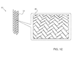
- Figure 1C is a magnified pictorial illustration of the braid produced by the braiding apparatus, in accordance with an embodiment of the present invention.
- FIG. 2 is a flow diagram that schematically illustrates a method of producing a magnetic resonance imaging (MRI) compatible probe, in accordance with an embodiment of the present invention.
- MRI magnetic resonance imaging
- Figure 3 is a schematic detail view showing a distal end of the MRI-compatible probe, in accordance with an embodiment of the present invention.
- MRI magnetic resonance imaging
- a radio frequency transmitter in an MRI system transmits an electromagnetic field.
- cells in the body transmit electromagnetic signals, which are detected by a scanner.
- the MRI image is then produced based on the received electromagnetic signals.
- any magnetic material in the area being visualized may distort the MRI image.
- exposing a magnetic object within the body to the MRI's strong magnetic field may cause a trauma to the patient due to movement of the magnetic object exposed to the magnetic field.
- Medical probes such as catheters, commonly contain a braided steel reinforcing layer for mechanical strength. This sort of steel layer, however, may create problematic effects when exposed to the strong magnetic field from the MRI system as described supra.
- Embodiments of the present invention provide a method and apparatus for producing a carbon ribbon, which when braided, can be used to produce a medical probe with a cylindrical carbon braid as reinforcement.
- a cylindrical carbon fiber is conveyed through a press such as a roller press, producing a flat, thin carbon ribbon.
- the ribbon is then woven into a cylindrical braid, which can be used as a reinforcement layer for a carbon-braided probe.
- Carbon-braided probes produced using embodiments of the present invention are typically comparable in both strength and flexibility to steel-braided probes, and are unaffected by the MRI's magnetic field. Furthermore, a carbon-braided probe can be used in other applications, in addition to procedures using MRI. For example, in multi-catheter procedures, the non-magnetic carbon braid in the catheter may be helpful in reducing magnetic field disturbance, which can otherwise affect position and force measurements made by other catheters.
- FIG. 1A is a pictorial illustration of an apparatus 20 for producing a carbon ribbon 36, in accordance with an embodiment of the present invention.
- An operator 24 inserts a cylindrical carbon fiber 26 into a roller press 28, and rotates a handle 30 to advance the carbon fiber through the roller press.
- carbon fiber 26 may have a diameter between approximately 50 ⁇ m and approximately 500 ⁇ m.
- Roller press 28 comprises two rollers 32, handle 30 and a pressure dial 34. Rotating pressure dial 34 increases or decreases the distance between the two rollers.
- Handle 30 is coupled to one or both of rollers 32.
- Operator 24 rotating handle 30 (counter-clockwise, in the example shown in Figure 1A ) conveys the carbon fiber between the two rollers, thereby producing flat, thin carbon ribbon 36.
- roller press 28 may include a motor coupled to one or both of rollers 32 in order to convey carbon fiber 26 between the two rollers.
- the dimensional specifications of ribbon 38 produced by roller press 28 has a width between 50 ⁇ m and 500 ⁇ m, and a thickness between 50 ⁇ m and 500 ⁇ m.
- operator 24 may insert multiple carbon fibers 26 simultaneously into roller press 28 thereby producing multiple flat carbon ribbons 36.
- Fig. 1B is a pictorial illustration of a braiding apparatus 38
- Fig 1C is a magnified pictorial illustration of a braid 48 produced by the braiding apparatus, in accordance with embodiments of the present invention.
- Braiding apparatus 38 is configured to create a cylindrical carbon braid 22 from ribbon 36.
- a braiding mechanism 44 conveys multiple ribbons 36 from multiple spools 46, and weaves braid 48 ( Fig. 1C ) surrounding the plastic tubing, thereby producing cylindrical carbon braid 22.
- FIG. 2 is a flow diagram that schematically illustrates a method of producing a magnetic resonance imaging (MRI) compatible probe in accordance with an embodiment of the present invention.
- operator 24 defines a range of dimensional specifications (i.e., length and width) for carbon ribbon 36.
- the ranges are typically based on the specifications of carbon ribbon 36, which may include ribbons of different dimensions. It will be appreciated that one of ordinary skill in the art may determine suitable dimensional ranges for the ribbon without undue experimentation.
- a compression step 51 operator 24 inserts cylindrical carbon fiber 26 into roller press 28, where rollers 32 compress the carbon fiber, thereby creating carbon ribbon 36.
- a comparison step 52 if ribbon 36 does not meet the dimensional specifications defined in step 50 (i.e., width and thickness), then the method returns to step 51. Typically, several passes through press 28 may be required to meet the defined dimensional specifications.
- a weaving step 54 operator 24 loads the ribbon to spools 46 of braiding apparatus 38, which then weaves the ribbon into cylindrical carbon braid 22.
- operator 24 cuts braid 22 to a pre-defined cut length to create a section of the braid and covers the section with a flexible, insulating, biocompatible material (also referred to herein as a sheath).
- a second probe producing step 58 operator 24 positions functional elements, such as cabling and/or tubing, within the braid, thereby producing an MRI-compatible probe, where the functional elements typically run between proximal and distal ends of the probe.
- Figure 3 is a schematic side view of an MRI-compatible probe 60, in accordance with an embodiment of the present invention. Specifically, Figure 3 shows functional elements of probe 60 used in creating a map of cardiac electrical activity.
- An electrode 64 at a distal tip 66 of the probe senses electrical signals in cardiac tissue. Alternatively, multiple electrodes (not shown) along the length of the probe may be used for this purpose.
- Electrode 64 is typically made of a metallic material, such as a platinum/iridium alloy or another suitable material.
- a position sensor 68 generates a signal that is indicative of the location coordinates of distal tip 66.
- Position sensor 68 may comprise an electrode, wherein impedances between the electrode and additional electrodes positioned outside a patient's body are measured to determine the position of the electrode.
- position sensor 68 may comprise a tri-coil position sensor (for example, as is implemented in the CARTOTM system produced by Biosense Webster, Inc., Diamond Bar, California) or an ultrasonic position sensor.
- Figure 3 shows a probe with a single position sensor, embodiments of the present invention may utilize probes with more than one position sensors.
- a force sensor 70 senses contact between distal tip 66 and endocardial tissue, by generating a signal that is indicative of the pressure exerted by distal tip 66 on the tissue.
- Probe 60 is covered by a biocompatible, flexible sheath 72.
- Sheath 72 is shown cut away in Figure 3 in order to expose cylindrical carbon braid 22, which is covered by the sheath.
- functional elements e.g., electrode 64, position sensor 68, force sensor 70, and any cabling
- the functional elements are typically constructed using non-magnetic materials. Using non-magnetic materials such as the platinum/iridium alloy described supra enables probe 60 to be MRI-compatible.
Landscapes
- Health & Medical Sciences (AREA)
- Life Sciences & Earth Sciences (AREA)
- Engineering & Computer Science (AREA)
- General Health & Medical Sciences (AREA)
- Veterinary Medicine (AREA)
- Animal Behavior & Ethology (AREA)
- Biomedical Technology (AREA)
- Heart & Thoracic Surgery (AREA)
- Public Health (AREA)
- Biophysics (AREA)
- Physics & Mathematics (AREA)
- Pathology (AREA)
- Surgery (AREA)
- Molecular Biology (AREA)
- Medical Informatics (AREA)
- Anesthesiology (AREA)
- Hematology (AREA)
- Pulmonology (AREA)
- Textile Engineering (AREA)
- Human Computer Interaction (AREA)
- Manufacturing & Machinery (AREA)
- General Physics & Mathematics (AREA)
- Condensed Matter Physics & Semiconductors (AREA)
- Physiology (AREA)
- Cardiology (AREA)
- Media Introduction/Drainage Providing Device (AREA)
- Magnetic Resonance Imaging Apparatus (AREA)
- Braiding, Manufacturing Of Bobbin-Net Or Lace, And Manufacturing Of Nets By Knotting (AREA)
- Electrotherapy Devices (AREA)
- Surgical Instruments (AREA)
- Materials For Medical Uses (AREA)
Abstract
Description
- The present invention relates generally to invasive probes, and specifically to producing a magnetic resonance imaging compatible catheter.
- A wide range of medical procedures involve placing objects, such as sensors, tubes, catheters, dispensing devices, and implants, within the body. When placing a medical probe fitted with position sensors within the body, a reference image of the body cavity being treated is typically presented on a display. The reference image assists a medical professional in positioning the probe to the appropriate location(s).
- An embodiment of the present invention provides a method, including,
- passing a cylindrical carbon fiber through a press so as to produce a flat ribbon; and
- weaving multiple strands of the flat ribbon together to create a cylindrical braid.
- Typically, the press includes a roller press. In one embodiment the carbon fiber has a diameter no greater than 500 µm.
- In a disclosed embodiment the method includes repeating passing the cylindrical carbon fiber through the press one or more times until the flat ribbon meets defined dimensional specifications. Typically, the dimensional specifications define a rectangle having a width no greater than 500 µm, and a thickness no greater than 500 µm.
- In an alternative embodiment the cylindrical braid is flexible. Typically, the method includes cutting the flexible cylindrical braid to a pre-defined cut length, thereby creating a section; covering the section with a flexible biocompatible sheath; and positioning one or more functional elements within the cut length of the braid, thereby producing a magnetic resonance imaging compatible medical probe.
- Each of the one or more functional elements may be selected from a list consisting of an electrode, a position sensor, a force sensor, cabling and tubing. The magnetic resonance imaging compatible probe typically consists of only non-magnetic materials.
- There is further provided, according to an embodiment of the present invention, a medical probe, which has proximal and distal ends and includes:
- a flexible cylindrical braid woven from multiple strands of a flat carbon ribbon;
- a flexible biocompatible sheath that is formed over the braid; and
- one or more functional elements running within the braid between the proximal and the distal end of the probe.
- Typically, the probe includes only non-magnetic materials.
- Each of the one or more functional elements may be selected from a list consisting of an electrode, a position sensor, a force sensor, cabling and tubing. Typically, the flat carbon ribbon has dimensional specifications defining a rectangle having a width no greater than 500 µm, and a thickness no greater than 500 µm.
- There is further provided, according to an embodiment of the present invention, a method, including:
- weaving a flexible cylindrical braid from multiple strands of a flat carbon ribbon;
- forming a flexible biocompatible sheath over the braid so as to produce a probe having proximal and distal ends; and
- running one or more functional elements within the braid between the proximal and the distal ends of the probe.
- There is further provided, according to an embodiment of the present invention, a method, including:
- forming a flexible biocompatible sheath over a flexible cylindrical braid woven from multiple strands of a flat carbon ribbon, so as to produce a probe having proximal and distal ends; and
- running one or more functional elements within the braid between the proximal and the distal ends of the probe.
- The disclosure is herein described, by way of example only, with reference to the accompanying drawings, wherein:
-
Figure 1A is a pictorial illustration of an apparatus for producing a carbon ribbon, in accordance with an embodiment of the present invention; -
Figure 1B is a pictorial illustration of a braiding apparatus used for producing a braid of the carbon ribbon, in accordance with an embodiment of the present invention; -
Figure 1C is a magnified pictorial illustration of the braid produced by the braiding apparatus, in accordance with an embodiment of the present invention; -
Figure 2 is a flow diagram that schematically illustrates a method of producing a magnetic resonance imaging (MRI) compatible probe, in accordance with an embodiment of the present invention; and -
Figure 3 is a schematic detail view showing a distal end of the MRI-compatible probe, in accordance with an embodiment of the present invention. - During some medical procedures, magnetic resonance imaging (MRI) is used to assist in visualizing detailed internal structures of the body. To produce an image using MRI, a radio frequency transmitter in an MRI system transmits an electromagnetic field. In response to the electromagnetic field, cells in the body transmit electromagnetic signals, which are detected by a scanner. The MRI image is then produced based on the received electromagnetic signals.
- Since MRI uses strong magnetic fields, any magnetic material in the area being visualized may distort the MRI image. In some instances, exposing a magnetic object within the body to the MRI's strong magnetic field may cause a trauma to the patient due to movement of the magnetic object exposed to the magnetic field.
- Medical probes, such as catheters, commonly contain a braided steel reinforcing layer for mechanical strength. This sort of steel layer, however, may create problematic effects when exposed to the strong magnetic field from the MRI system as described supra.
- Embodiments of the present invention provide a method and apparatus for producing a carbon ribbon, which when braided, can be used to produce a medical probe with a cylindrical carbon braid as reinforcement. In some embodiments, a cylindrical carbon fiber is conveyed through a press such as a roller press, producing a flat, thin carbon ribbon. The ribbon is then woven into a cylindrical braid, which can be used as a reinforcement layer for a carbon-braided probe.
- Carbon-braided probes produced using embodiments of the present invention are typically comparable in both strength and flexibility to steel-braided probes, and are unaffected by the MRI's magnetic field. Furthermore, a carbon-braided probe can be used in other applications, in addition to procedures using MRI. For example, in multi-catheter procedures, the non-magnetic carbon braid in the catheter may be helpful in reducing magnetic field disturbance, which can otherwise affect position and force measurements made by other catheters.
-
Figure 1A is a pictorial illustration of anapparatus 20 for producing acarbon ribbon 36, in accordance with an embodiment of the present invention. Anoperator 24 inserts a cylindrical carbon fiber 26 into aroller press 28, and rotates a handle 30 to advance the carbon fiber through the roller press. In some embodiments, carbon fiber 26 may have a diameter between approximately 50 µm and approximately 500 µm. -
Roller press 28 comprises tworollers 32, handle 30 and apressure dial 34. Rotatingpressure dial 34 increases or decreases the distance between the two rollers. Handle 30 is coupled to one or both ofrollers 32.Operator 24 rotating handle 30 (counter-clockwise, in the example shown inFigure 1A ) conveys the carbon fiber between the two rollers, thereby producing flat,thin carbon ribbon 36. Alternatively,roller press 28 may include a motor coupled to one or both ofrollers 32 in order to convey carbon fiber 26 between the two rollers. Using the carbon ribbon whose dimensions are described supra, the dimensional specifications ofribbon 38 produced byroller press 28 has a width between 50 µm and 500 µm, and a thickness between 50 µm and 500 µm. In some embodiments,operator 24 may insert multiple carbon fibers 26 simultaneously intoroller press 28 thereby producing multipleflat carbon ribbons 36. -
Fig. 1B is a pictorial illustration of abraiding apparatus 38, andFig 1C is a magnified pictorial illustration of abraid 48 produced by the braiding apparatus, in accordance with embodiments of the present invention.Braiding apparatus 38 is configured to create acylindrical carbon braid 22 fromribbon 36. As arotating wheel 40 conveys a flexibleplastic tubing 42 through the braiding machine, abraiding mechanism 44 conveysmultiple ribbons 36 frommultiple spools 46, and weaves braid 48 (Fig. 1C ) surrounding the plastic tubing, thereby producingcylindrical carbon braid 22. -
Figure 2 is a flow diagram that schematically illustrates a method of producing a magnetic resonance imaging (MRI) compatible probe in accordance with an embodiment of the present invention. In aninitial step 50,operator 24 defines a range of dimensional specifications (i.e., length and width) forcarbon ribbon 36. The ranges are typically based on the specifications ofcarbon ribbon 36, which may include ribbons of different dimensions. It will be appreciated that one of ordinary skill in the art may determine suitable dimensional ranges for the ribbon without undue experimentation. - In a
compression step 51,operator 24 inserts cylindrical carbon fiber 26 intoroller press 28, whererollers 32 compress the carbon fiber, thereby creatingcarbon ribbon 36. In acomparison step 52, ifribbon 36 does not meet the dimensional specifications defined in step 50 (i.e., width and thickness), then the method returns to step 51. Typically, several passes throughpress 28 may be required to meet the defined dimensional specifications. - If, however,
ribbon 36 meets the defined dimensional specifications, then in a weavingstep 54,operator 24 loads the ribbon tospools 46 ofbraiding apparatus 38, which then weaves the ribbon intocylindrical carbon braid 22. In a firstprobe producing step 56,operator 24 cuts braid 22 to a pre-defined cut length to create a section of the braid and covers the section with a flexible, insulating, biocompatible material (also referred to herein as a sheath). Finally, in a secondprobe producing step 58,operator 24 positions functional elements, such as cabling and/or tubing, within the braid, thereby producing an MRI-compatible probe, where the functional elements typically run between proximal and distal ends of the probe. -
Figure 3 is a schematic side view of an MRI-compatible probe 60, in accordance with an embodiment of the present invention. Specifically,Figure 3 shows functional elements ofprobe 60 used in creating a map of cardiac electrical activity. Anelectrode 64 at adistal tip 66 of the probe senses electrical signals in cardiac tissue. Alternatively, multiple electrodes (not shown) along the length of the probe may be used for this purpose.Electrode 64 is typically made of a metallic material, such as a platinum/iridium alloy or another suitable material. - A
position sensor 68 generates a signal that is indicative of the location coordinates ofdistal tip 66.Position sensor 68 may comprise an electrode, wherein impedances between the electrode and additional electrodes positioned outside a patient's body are measured to determine the position of the electrode. In alternative embodiments,position sensor 68 may comprise a tri-coil position sensor (for example, as is implemented in the CARTO™ system produced by Biosense Webster, Inc., Diamond Bar, California) or an ultrasonic position sensor. AlthoughFigure 3 shows a probe with a single position sensor, embodiments of the present invention may utilize probes with more than one position sensors. - A
force sensor 70 senses contact betweendistal tip 66 and endocardial tissue, by generating a signal that is indicative of the pressure exerted bydistal tip 66 on the tissue. -
Probe 60 is covered by a biocompatible,flexible sheath 72.Sheath 72 is shown cut away inFigure 3 in order to exposecylindrical carbon braid 22, which is covered by the sheath. In embodiments of the present invention, functional elements (e.g.,electrode 64,position sensor 68,force sensor 70, and any cabling) are withinsheath 72 and run between adistal end 62 and aproximal end 74 of the probe. The functional elements are typically constructed using non-magnetic materials. Using non-magnetic materials such as the platinum/iridium alloy described supra enablesprobe 60 to be MRI-compatible. - It will be appreciated that the embodiments described above are cited by way of example, and that the present invention is not limited to what has been particularly shown and described hereinabove. Rather, the scope of the present invention includes both combinations and subcombinations of the various features described hereinabove, as well as variations and modifications thereof which would occur to persons skilled in the art upon reading the foregoing description and which are not disclosed in the prior art.
Claims (15)
- A method, comprising,
passing a cylindrical carbon fiber through a press so as to produce a flat ribbon; and
weaving multiple strands of the flat ribbon together to create a cylindrical braid. - The method according to claim 1, wherein the press comprises a roller press.
- The method according to claim 1, wherein the carbon fiber has a diameter no greater than 500 µm.
- The method according to claim 1, and comprising repeating passing the cylindrical carbon fiber through the press one or more times until the flat ribbon meets defined dimensional specifications.
- The method according to claim 4, wherein the dimensional specifications define a rectangle having a width no greater than 500 µm, and a thickness no greater than 500 µm.
- The method according to claim 1, wherein the cylindrical braid is flexible.
- The method according to claim 6, and comprising:cutting the flexible cylindrical braid to a pre-defined cut length, thereby creating a section;covering the section with a flexible biocompatible sheath; andpositioning one or more functional elements within the cut length of the braid, thereby producing a magnetic resonance imaging compatible medical probe.
- The method according to claim 7, wherein each of the one or more functional elements is selected from a list consisting of an electrode, a position sensor, a force sensor, cabling and tubing.
- The method according to claim 7, wherein the magnetic resonance imaging compatible probe comprises only non-magnetic materials.
- A medical probe, which has proximal and distal ends and comprises:a flexible cylindrical braid woven from multiple strands of a flat carbon ribbon;a flexible biocompatible sheath that is formed over the braid; andone or more functional elements running within the braid between the proximal and the distal end of the probe.
- A method, comprising:weaving a flexible cylindrical braid from multiple strands of a flat carbon ribbon;forming a flexible biocompatible sheath over the braid so as to produce a probe having proximal and distal ends; andrunning one or more functional elements within the braid between the proximal and the distal ends of the probe.
- The medical probe according to claim 10 or the method according to claim 11, wherein the probe comprises only non-magnetic materials.
- The medical probe according to claim 10 or the method according to claim 11, wherein each of the one or more functional elements is selected from a list consisting of an electrode, a position sensor, a force sensor, cabling and tubing.
- The medical probe according to claim 10 or the method according to claim 11, wherein the flat carbon ribbon has dimensional specifications defining a rectangle having a width no greater than 500 µm, and a thickness no greater than 500 µm.
- A method, comprising:forming a flexible biocompatible sheath over a flexible cylindrical braid woven from multiple strands of a flat carbon ribbon, so as to produce a probe having proximal and distal ends; andrunning one or more functional elements within the braid between the proximal and the distal ends of the probe.
Applications Claiming Priority (1)
| Application Number | Priority Date | Filing Date | Title |
|---|---|---|---|
| US12/958,679 US8857304B2 (en) | 2010-12-02 | 2010-12-02 | Magnetic resonance imaging compatible catheter |
Publications (2)
| Publication Number | Publication Date |
|---|---|
| EP2460557A1 true EP2460557A1 (en) | 2012-06-06 |
| EP2460557B1 EP2460557B1 (en) | 2020-11-18 |
Family
ID=45094538
Family Applications (1)
| Application Number | Title | Priority Date | Filing Date |
|---|---|---|---|
| EP11191572.4A Active EP2460557B1 (en) | 2010-12-02 | 2011-12-01 | Magnetic resonance imaging compatible catheter |
Country Status (7)
| Country | Link |
|---|---|
| US (2) | US8857304B2 (en) |
| EP (1) | EP2460557B1 (en) |
| JP (1) | JP6430093B2 (en) |
| CN (1) | CN102560878B (en) |
| AU (1) | AU2011253709B2 (en) |
| CA (1) | CA2759995C (en) |
| IL (1) | IL216506A (en) |
Families Citing this family (14)
| Publication number | Priority date | Publication date | Assignee | Title |
|---|---|---|---|---|
| US8857304B2 (en) * | 2010-12-02 | 2014-10-14 | Biosense Webster (Israel), Ltd. | Magnetic resonance imaging compatible catheter |
| JP6084057B2 (en) * | 2013-02-07 | 2017-02-22 | 株式会社市川鉄工 | Torsion racing machine |
| JP6084058B2 (en) * | 2013-02-07 | 2017-02-22 | 株式会社市川鉄工 | Torsion racing machine |
| US9289265B2 (en) * | 2013-07-10 | 2016-03-22 | The Johns Hopkins University | MRI-compatible, integrated force and torque sensors and systems that incorporate the sensors |
| US8956394B1 (en) | 2014-08-05 | 2015-02-17 | Woven Orthopedic Technologies, Llc | Woven retention devices, systems and methods |
| US9907593B2 (en) | 2014-08-05 | 2018-03-06 | Woven Orthopedic Technologies, Llc | Woven retention devices, systems and methods |
| US20160074071A1 (en) | 2014-09-16 | 2016-03-17 | Woven Orthopedic Technologies, Llc | Methods of using woven retention devices and systems |
| US20160168769A1 (en) * | 2014-12-12 | 2016-06-16 | Woven Orthopedic Technologies, Llc | Methods and systems for manufacturing woven retention devices |
| EP3331459A4 (en) | 2015-08-05 | 2019-08-14 | Woven Orthopedic Technologies, LLC | Tapping devices, systems and methods for use in bone tissue |
| US10575754B2 (en) | 2015-09-23 | 2020-03-03 | Covidien Lp | Catheter having a sensor and an extended working channel |
| EP3551105A4 (en) | 2016-12-09 | 2020-07-29 | Woven Orthopedic Technologies, LLC | Retention devices, lattices and related systems and methods |
| US10773051B2 (en) | 2018-01-24 | 2020-09-15 | Covidien Lp | Methods of manufacturing a catheter having a sensor |
| US10773053B2 (en) | 2018-01-24 | 2020-09-15 | Covidien Lp | Methods of manufacturing a catheter having a sensor |
| JP7325047B2 (en) * | 2020-01-17 | 2023-08-14 | オリンパス株式会社 | Circular braid-making machine for waveguide outer conductor and method for manufacturing flexible waveguide |
Citations (7)
| Publication number | Priority date | Publication date | Assignee | Title |
|---|---|---|---|---|
| EP0444728A1 (en) * | 1990-02-26 | 1991-09-04 | Cordis Europa N.V. | Method and device for manufacturing a catheter with braided sheath |
| EP0806596A1 (en) * | 1996-04-30 | 1997-11-12 | Target Therapeutics, Inc. | Super-elastic alloy braid structure |
| US5906606A (en) * | 1995-12-04 | 1999-05-25 | Target Therapuetics, Inc. | Braided body balloon catheter |
| US20030216642A1 (en) * | 2002-05-16 | 2003-11-20 | Pepin Henry J. | Radiopaque and MRI compatible catheter braid |
| EP1374717A2 (en) * | 2002-06-25 | 2004-01-02 | Orocinque S.P.A. | A process for the production of bi-coloured ornamental items |
| US20060095050A1 (en) * | 2004-09-14 | 2006-05-04 | William A. Cook Australia Pty. Ltd. | Large diameter sheath |
| EP2213325A1 (en) * | 2007-10-26 | 2010-08-04 | Terumo Kabushiki Kaisha | Catheter |
Family Cites Families (30)
| Publication number | Priority date | Publication date | Assignee | Title |
|---|---|---|---|---|
| US5411527A (en) * | 1989-05-03 | 1995-05-02 | Intermedics, Inc. | Difibrillation electrodes and implantation |
| JPH048751A (en) | 1990-04-26 | 1992-01-13 | Sekisui Chem Co Ltd | Acrylic resin composition |
| US5569220A (en) * | 1991-01-24 | 1996-10-29 | Cordis Webster, Inc. | Cardiovascular catheter having high torsional stiffness |
| JPH0613846U (en) * | 1992-02-26 | 1994-02-22 | 富士システムズ株式会社 | Medical catheter |
| JP3114908B2 (en) * | 1992-11-16 | 2000-12-04 | 三菱電線工業株式会社 | Rigid inclined torque tube, method for manufacturing the same, and catheter using the torque tube |
| US5633074A (en) | 1993-06-07 | 1997-05-27 | Yamaha Corporation | Prepreg available for fiber reinforced thermoplastic resin and process of producing sporting goods using the same |
| JPH06346337A (en) * | 1993-06-07 | 1994-12-20 | Yamaha Corp | Sleeve for fiber-reinforced thermoplastic resin |
| US5454795A (en) * | 1994-06-27 | 1995-10-03 | Target Therapeutics, Inc. | Kink-free spiral-wound catheter |
| US5701905A (en) * | 1995-11-13 | 1997-12-30 | Localmed, Inc. | Guide catheter with sensing element |
| US6110591A (en) * | 1997-04-23 | 2000-08-29 | Slade Group, Llc | Compressed high temperature non-asbestos sheet and method for making the same |
| US5891114A (en) * | 1997-09-30 | 1999-04-06 | Target Therapeutics, Inc. | Soft-tip high performance braided catheter |
| US5954649A (en) * | 1997-10-20 | 1999-09-21 | Irvine Biomedical, Inc. | Catheter system having ultrasound locating capabilities |
| US20030208252A1 (en) * | 2001-05-14 | 2003-11-06 | O' Boyle Gary S. | Mri ablation catheter |
| US20030144718A1 (en) * | 2002-01-29 | 2003-07-31 | Zeijlemaker Volkert A. | Method and apparatus for shielding coating for MRI resistant electrode systems |
| US7182898B2 (en) * | 2002-05-13 | 2007-02-27 | Advanced Energy Technology Inc. | Process for complex shape formation using flexible graphite sheets |
| NO20025711D0 (en) * | 2002-11-27 | 2002-11-27 | Amersham Health As | Magnetic resonance method |
| US8636714B2 (en) | 2003-09-22 | 2014-01-28 | Boston Scientific Scimed, Inc. | Microcatheter with sleeved guidewire port |
| US7998112B2 (en) | 2003-09-30 | 2011-08-16 | Abbott Cardiovascular Systems Inc. | Deflectable catheter assembly and method of making same |
| US20070021667A1 (en) * | 2005-05-19 | 2007-01-25 | Biophan Technologies, Inc. | Electromagnetic resonant circuit sleeve for implantable medical device |
| US8639311B2 (en) * | 2005-09-08 | 2014-01-28 | Philadelphia Health & Education Corporation | Sensing probe comprising multiple, spatially separate, sensing sites |
| JP4842615B2 (en) * | 2005-10-28 | 2011-12-21 | 金井 宏彰 | Catheter reinforcement |
| JP2007307070A (en) * | 2006-05-17 | 2007-11-29 | Terumo Corp | Medical apparatus and catheter for removing intravascular foreign matter |
| EP2080535A4 (en) * | 2006-11-07 | 2012-10-17 | Kaneka Corp | Catheter tube for medical use |
| US8182466B2 (en) * | 2006-12-29 | 2012-05-22 | St. Jude Medical, Atrial Fibrillation Division, Inc. | Dual braided catheter shaft |
| US8357152B2 (en) * | 2007-10-08 | 2013-01-22 | Biosense Webster (Israel), Ltd. | Catheter with pressure sensing |
| US8684999B2 (en) * | 2007-12-31 | 2014-04-01 | St. Jude Medical, Atrial Fibrillation Division, Inc. | Catheter shaft and method of manufacture |
| US20090282802A1 (en) * | 2008-05-15 | 2009-11-19 | Cooper Christopher H | Carbon nanotube yarn, thread, rope, fabric and composite and methods of making the same |
| US20100126985A1 (en) * | 2008-06-13 | 2010-05-27 | Tsinghua University | Carbon nanotube heater |
| US8594761B2 (en) * | 2010-03-03 | 2013-11-26 | Pacesetter, Inc. | Crimp terminations for conductors in implantable medical lead and method of making same |
| US8857304B2 (en) * | 2010-12-02 | 2014-10-14 | Biosense Webster (Israel), Ltd. | Magnetic resonance imaging compatible catheter |
-
2010
- 2010-12-02 US US12/958,679 patent/US8857304B2/en active Active
-
2011
- 2011-11-21 IL IL216506A patent/IL216506A/en active IP Right Grant
- 2011-11-28 AU AU2011253709A patent/AU2011253709B2/en not_active Ceased
- 2011-11-30 CA CA2759995A patent/CA2759995C/en not_active Expired - Fee Related
- 2011-12-01 JP JP2011263377A patent/JP6430093B2/en not_active Expired - Fee Related
- 2011-12-01 EP EP11191572.4A patent/EP2460557B1/en active Active
- 2011-12-02 CN CN201110411347.1A patent/CN102560878B/en not_active Expired - Fee Related
-
2014
- 2014-09-12 US US14/484,461 patent/US10173028B2/en active Active
Patent Citations (7)
| Publication number | Priority date | Publication date | Assignee | Title |
|---|---|---|---|---|
| EP0444728A1 (en) * | 1990-02-26 | 1991-09-04 | Cordis Europa N.V. | Method and device for manufacturing a catheter with braided sheath |
| US5906606A (en) * | 1995-12-04 | 1999-05-25 | Target Therapuetics, Inc. | Braided body balloon catheter |
| EP0806596A1 (en) * | 1996-04-30 | 1997-11-12 | Target Therapeutics, Inc. | Super-elastic alloy braid structure |
| US20030216642A1 (en) * | 2002-05-16 | 2003-11-20 | Pepin Henry J. | Radiopaque and MRI compatible catheter braid |
| EP1374717A2 (en) * | 2002-06-25 | 2004-01-02 | Orocinque S.P.A. | A process for the production of bi-coloured ornamental items |
| US20060095050A1 (en) * | 2004-09-14 | 2006-05-04 | William A. Cook Australia Pty. Ltd. | Large diameter sheath |
| EP2213325A1 (en) * | 2007-10-26 | 2010-08-04 | Terumo Kabushiki Kaisha | Catheter |
Also Published As
| Publication number | Publication date |
|---|---|
| US20140378806A1 (en) | 2014-12-25 |
| AU2011253709B2 (en) | 2014-09-11 |
| US20120143044A1 (en) | 2012-06-07 |
| JP6430093B2 (en) | 2018-11-28 |
| CN102560878B (en) | 2016-05-11 |
| CA2759995C (en) | 2019-03-05 |
| AU2011253709A1 (en) | 2012-06-21 |
| JP2012115678A (en) | 2012-06-21 |
| IL216506A (en) | 2017-02-28 |
| CN102560878A (en) | 2012-07-11 |
| US8857304B2 (en) | 2014-10-14 |
| US10173028B2 (en) | 2019-01-08 |
| EP2460557B1 (en) | 2020-11-18 |
| CA2759995A1 (en) | 2012-06-02 |
| IL216506A0 (en) | 2012-01-31 |
Similar Documents
| Publication | Publication Date | Title |
|---|---|---|
| US8857304B2 (en) | Magnetic resonance imaging compatible catheter | |
| JP7193875B2 (en) | Magnetic markers for surgical guidance | |
| US9375549B2 (en) | Reducing mechanical stress on conductors and connection points in a position determinable interventional medical device | |
| CN101416874B (en) | Catheter with pressure sensing | |
| JP2955484B2 (en) | Magnetic resonance imaging device for tracking medical instruments | |
| EP3958774B1 (en) | Reduced impedance electrode design | |
| EP3344134B1 (en) | Multi-layer body surface electrodes | |
| JP2005508718A (en) | Ceramic reinforcement for MRI equipment | |
| CN103298392A (en) | Medical devices having an electroanatomical system imaging element mounted thereon | |
| JP2018069061A (en) | Guide wire with improved mechanical strength and electromagnetic shielding | |
| US20160276739A1 (en) | Field concentrating antennas for magnetic position sensors | |
| CN105431194A (en) | Actively tracked medical devices | |
| US9383421B2 (en) | Intra-body medical devices for use in MRI environments | |
| EP3056139A1 (en) | Navigation of an angioplasty guidewire | |
| EP2358287B1 (en) | Stylet for use with image guided systems | |
| WO2012094365A2 (en) | Single channel mri guidewire | |
| US20230329577A1 (en) | Magnetic Position Sensor and Cable | |
| US20210244483A1 (en) | Guidewire |
Legal Events
| Date | Code | Title | Description |
|---|---|---|---|
| PUAI | Public reference made under article 153(3) epc to a published international application that has entered the european phase |
Free format text: ORIGINAL CODE: 0009012 |
|
| AK | Designated contracting states |
Kind code of ref document: A1 Designated state(s): AL AT BE BG CH CY CZ DE DK EE ES FI FR GB GR HR HU IE IS IT LI LT LU LV MC MK MT NL NO PL PT RO RS SE SI SK SM TR |
|
| AX | Request for extension of the european patent |
Extension state: BA ME |
|
| 17P | Request for examination filed |
Effective date: 20121106 |
|
| STAA | Information on the status of an ep patent application or granted ep patent |
Free format text: STATUS: EXAMINATION IS IN PROGRESS |
|
| 17Q | First examination report despatched |
Effective date: 20170405 |
|
| RIC1 | Information provided on ipc code assigned before grant |
Ipc: A61M 25/00 20060101AFI20200109BHEP Ipc: A61B 5/055 20060101ALN20200109BHEP Ipc: A61B 5/06 20060101ALI20200109BHEP Ipc: A61B 5/00 20060101ALI20200109BHEP |
|
| GRAP | Despatch of communication of intention to grant a patent |
Free format text: ORIGINAL CODE: EPIDOSNIGR1 |
|
| STAA | Information on the status of an ep patent application or granted ep patent |
Free format text: STATUS: GRANT OF PATENT IS INTENDED |
|
| INTG | Intention to grant announced |
Effective date: 20200226 |
|
| GRAJ | Information related to disapproval of communication of intention to grant by the applicant or resumption of examination proceedings by the epo deleted |
Free format text: ORIGINAL CODE: EPIDOSDIGR1 |
|
| STAA | Information on the status of an ep patent application or granted ep patent |
Free format text: STATUS: EXAMINATION IS IN PROGRESS |
|
| RAP1 | Party data changed (applicant data changed or rights of an application transferred) |
Owner name: BIOSENSE WEBSTER (ISRAEL) LTD. |
|
| INTC | Intention to grant announced (deleted) | ||
| RIC1 | Information provided on ipc code assigned before grant |
Ipc: A61B 5/06 20060101ALI20200610BHEP Ipc: A61B 5/00 20060101ALI20200610BHEP Ipc: A61B 5/055 20060101ALN20200610BHEP Ipc: A61M 25/00 20060101AFI20200610BHEP |
|
| GRAP | Despatch of communication of intention to grant a patent |
Free format text: ORIGINAL CODE: EPIDOSNIGR1 |
|
| STAA | Information on the status of an ep patent application or granted ep patent |
Free format text: STATUS: GRANT OF PATENT IS INTENDED |
|
| INTG | Intention to grant announced |
Effective date: 20200730 |
|
| GRAS | Grant fee paid |
Free format text: ORIGINAL CODE: EPIDOSNIGR3 |
|
| GRAA | (expected) grant |
Free format text: ORIGINAL CODE: 0009210 |
|
| STAA | Information on the status of an ep patent application or granted ep patent |
Free format text: STATUS: THE PATENT HAS BEEN GRANTED |
|
| AK | Designated contracting states |
Kind code of ref document: B1 Designated state(s): AL AT BE BG CH CY CZ DE DK EE ES FI FR GB GR HR HU IE IS IT LI LT LU LV MC MK MT NL NO PL PT RO RS SE SI SK SM TR |
|
| RAP1 | Party data changed (applicant data changed or rights of an application transferred) |
Owner name: BIOSENSE WEBSTER (ISRAEL) LTD. |
|
| REG | Reference to a national code |
Ref country code: GB Ref legal event code: FG4D |
|
| REG | Reference to a national code |
Ref country code: CH Ref legal event code: EP |
|
| REG | Reference to a national code |
Ref country code: IE Ref legal event code: FG4D |
|
| REG | Reference to a national code |
Ref country code: DE Ref legal event code: R096 Ref document number: 602011069329 Country of ref document: DE |
|
| REG | Reference to a national code |
Ref country code: AT Ref legal event code: REF Ref document number: 1335074 Country of ref document: AT Kind code of ref document: T Effective date: 20201215 |
|
| REG | Reference to a national code |
Ref country code: NL Ref legal event code: FP |
|
| REG | Reference to a national code |
Ref country code: AT Ref legal event code: MK05 Ref document number: 1335074 Country of ref document: AT Kind code of ref document: T Effective date: 20201118 |
|
| PG25 | Lapsed in a contracting state [announced via postgrant information from national office to epo] |
Ref country code: GR Free format text: LAPSE BECAUSE OF FAILURE TO SUBMIT A TRANSLATION OF THE DESCRIPTION OR TO PAY THE FEE WITHIN THE PRESCRIBED TIME-LIMIT Effective date: 20210219 Ref country code: PT Free format text: LAPSE BECAUSE OF FAILURE TO SUBMIT A TRANSLATION OF THE DESCRIPTION OR TO PAY THE FEE WITHIN THE PRESCRIBED TIME-LIMIT Effective date: 20210318 Ref country code: NO Free format text: LAPSE BECAUSE OF FAILURE TO SUBMIT A TRANSLATION OF THE DESCRIPTION OR TO PAY THE FEE WITHIN THE PRESCRIBED TIME-LIMIT Effective date: 20210218 Ref country code: FI Free format text: LAPSE BECAUSE OF FAILURE TO SUBMIT A TRANSLATION OF THE DESCRIPTION OR TO PAY THE FEE WITHIN THE PRESCRIBED TIME-LIMIT Effective date: 20201118 Ref country code: RS Free format text: LAPSE BECAUSE OF FAILURE TO SUBMIT A TRANSLATION OF THE DESCRIPTION OR TO PAY THE FEE WITHIN THE PRESCRIBED TIME-LIMIT Effective date: 20201118 |
|
| PG25 | Lapsed in a contracting state [announced via postgrant information from national office to epo] |
Ref country code: LV Free format text: LAPSE BECAUSE OF FAILURE TO SUBMIT A TRANSLATION OF THE DESCRIPTION OR TO PAY THE FEE WITHIN THE PRESCRIBED TIME-LIMIT Effective date: 20201118 Ref country code: SE Free format text: LAPSE BECAUSE OF FAILURE TO SUBMIT A TRANSLATION OF THE DESCRIPTION OR TO PAY THE FEE WITHIN THE PRESCRIBED TIME-LIMIT Effective date: 20201118 Ref country code: PL Free format text: LAPSE BECAUSE OF FAILURE TO SUBMIT A TRANSLATION OF THE DESCRIPTION OR TO PAY THE FEE WITHIN THE PRESCRIBED TIME-LIMIT Effective date: 20201118 Ref country code: IS Free format text: LAPSE BECAUSE OF FAILURE TO SUBMIT A TRANSLATION OF THE DESCRIPTION OR TO PAY THE FEE WITHIN THE PRESCRIBED TIME-LIMIT Effective date: 20210318 Ref country code: BG Free format text: LAPSE BECAUSE OF FAILURE TO SUBMIT A TRANSLATION OF THE DESCRIPTION OR TO PAY THE FEE WITHIN THE PRESCRIBED TIME-LIMIT Effective date: 20210218 Ref country code: AT Free format text: LAPSE BECAUSE OF FAILURE TO SUBMIT A TRANSLATION OF THE DESCRIPTION OR TO PAY THE FEE WITHIN THE PRESCRIBED TIME-LIMIT Effective date: 20201118 |
|
| REG | Reference to a national code |
Ref country code: LT Ref legal event code: MG9D |
|
| PG25 | Lapsed in a contracting state [announced via postgrant information from national office to epo] |
Ref country code: HR Free format text: LAPSE BECAUSE OF FAILURE TO SUBMIT A TRANSLATION OF THE DESCRIPTION OR TO PAY THE FEE WITHIN THE PRESCRIBED TIME-LIMIT Effective date: 20201118 |
|
| PG25 | Lapsed in a contracting state [announced via postgrant information from national office to epo] |
Ref country code: LT Free format text: LAPSE BECAUSE OF FAILURE TO SUBMIT A TRANSLATION OF THE DESCRIPTION OR TO PAY THE FEE WITHIN THE PRESCRIBED TIME-LIMIT Effective date: 20201118 Ref country code: SK Free format text: LAPSE BECAUSE OF FAILURE TO SUBMIT A TRANSLATION OF THE DESCRIPTION OR TO PAY THE FEE WITHIN THE PRESCRIBED TIME-LIMIT Effective date: 20201118 Ref country code: RO Free format text: LAPSE BECAUSE OF FAILURE TO SUBMIT A TRANSLATION OF THE DESCRIPTION OR TO PAY THE FEE WITHIN THE PRESCRIBED TIME-LIMIT Effective date: 20201118 Ref country code: CZ Free format text: LAPSE BECAUSE OF FAILURE TO SUBMIT A TRANSLATION OF THE DESCRIPTION OR TO PAY THE FEE WITHIN THE PRESCRIBED TIME-LIMIT Effective date: 20201118 Ref country code: EE Free format text: LAPSE BECAUSE OF FAILURE TO SUBMIT A TRANSLATION OF THE DESCRIPTION OR TO PAY THE FEE WITHIN THE PRESCRIBED TIME-LIMIT Effective date: 20201118 Ref country code: SM Free format text: LAPSE BECAUSE OF FAILURE TO SUBMIT A TRANSLATION OF THE DESCRIPTION OR TO PAY THE FEE WITHIN THE PRESCRIBED TIME-LIMIT Effective date: 20201118 |
|
| REG | Reference to a national code |
Ref country code: CH Ref legal event code: PL |
|
| REG | Reference to a national code |
Ref country code: DE Ref legal event code: R097 Ref document number: 602011069329 Country of ref document: DE |
|
| PG25 | Lapsed in a contracting state [announced via postgrant information from national office to epo] |
Ref country code: DK Free format text: LAPSE BECAUSE OF FAILURE TO SUBMIT A TRANSLATION OF THE DESCRIPTION OR TO PAY THE FEE WITHIN THE PRESCRIBED TIME-LIMIT Effective date: 20201118 Ref country code: MC Free format text: LAPSE BECAUSE OF FAILURE TO SUBMIT A TRANSLATION OF THE DESCRIPTION OR TO PAY THE FEE WITHIN THE PRESCRIBED TIME-LIMIT Effective date: 20201118 |
|
| REG | Reference to a national code |
Ref country code: BE Ref legal event code: MM Effective date: 20201231 |
|
| PLBE | No opposition filed within time limit |
Free format text: ORIGINAL CODE: 0009261 |
|
| STAA | Information on the status of an ep patent application or granted ep patent |
Free format text: STATUS: NO OPPOSITION FILED WITHIN TIME LIMIT |
|
| 26N | No opposition filed |
Effective date: 20210819 |
|
| PG25 | Lapsed in a contracting state [announced via postgrant information from national office to epo] |
Ref country code: LU Free format text: LAPSE BECAUSE OF NON-PAYMENT OF DUE FEES Effective date: 20201201 Ref country code: AL Free format text: LAPSE BECAUSE OF FAILURE TO SUBMIT A TRANSLATION OF THE DESCRIPTION OR TO PAY THE FEE WITHIN THE PRESCRIBED TIME-LIMIT Effective date: 20201118 Ref country code: IE Free format text: LAPSE BECAUSE OF NON-PAYMENT OF DUE FEES Effective date: 20201201 |
|
| PG25 | Lapsed in a contracting state [announced via postgrant information from national office to epo] |
Ref country code: ES Free format text: LAPSE BECAUSE OF FAILURE TO SUBMIT A TRANSLATION OF THE DESCRIPTION OR TO PAY THE FEE WITHIN THE PRESCRIBED TIME-LIMIT Effective date: 20201118 Ref country code: CH Free format text: LAPSE BECAUSE OF NON-PAYMENT OF DUE FEES Effective date: 20201231 Ref country code: SI Free format text: LAPSE BECAUSE OF FAILURE TO SUBMIT A TRANSLATION OF THE DESCRIPTION OR TO PAY THE FEE WITHIN THE PRESCRIBED TIME-LIMIT Effective date: 20201118 Ref country code: LI Free format text: LAPSE BECAUSE OF NON-PAYMENT OF DUE FEES Effective date: 20201231 |
|
| PG25 | Lapsed in a contracting state [announced via postgrant information from national office to epo] |
Ref country code: IS Free format text: LAPSE BECAUSE OF FAILURE TO SUBMIT A TRANSLATION OF THE DESCRIPTION OR TO PAY THE FEE WITHIN THE PRESCRIBED TIME-LIMIT Effective date: 20210318 Ref country code: TR Free format text: LAPSE BECAUSE OF FAILURE TO SUBMIT A TRANSLATION OF THE DESCRIPTION OR TO PAY THE FEE WITHIN THE PRESCRIBED TIME-LIMIT Effective date: 20201118 Ref country code: MT Free format text: LAPSE BECAUSE OF FAILURE TO SUBMIT A TRANSLATION OF THE DESCRIPTION OR TO PAY THE FEE WITHIN THE PRESCRIBED TIME-LIMIT Effective date: 20201118 Ref country code: CY Free format text: LAPSE BECAUSE OF FAILURE TO SUBMIT A TRANSLATION OF THE DESCRIPTION OR TO PAY THE FEE WITHIN THE PRESCRIBED TIME-LIMIT Effective date: 20201118 |
|
| PG25 | Lapsed in a contracting state [announced via postgrant information from national office to epo] |
Ref country code: MK Free format text: LAPSE BECAUSE OF FAILURE TO SUBMIT A TRANSLATION OF THE DESCRIPTION OR TO PAY THE FEE WITHIN THE PRESCRIBED TIME-LIMIT Effective date: 20201118 |
|
| PG25 | Lapsed in a contracting state [announced via postgrant information from national office to epo] |
Ref country code: BE Free format text: LAPSE BECAUSE OF NON-PAYMENT OF DUE FEES Effective date: 20201231 |
|
| PGFP | Annual fee paid to national office [announced via postgrant information from national office to epo] |
Ref country code: NL Payment date: 20221114 Year of fee payment: 12 Ref country code: IT Payment date: 20221111 Year of fee payment: 12 Ref country code: GB Payment date: 20221103 Year of fee payment: 12 Ref country code: FR Payment date: 20221110 Year of fee payment: 12 Ref country code: DE Payment date: 20220622 Year of fee payment: 12 |
|
| REG | Reference to a national code |
Ref country code: DE Ref legal event code: R119 Ref document number: 602011069329 Country of ref document: DE |
|
| REG | Reference to a national code |
Ref country code: NL Ref legal event code: MM Effective date: 20240101 |
|
| GBPC | Gb: european patent ceased through non-payment of renewal fee |
Effective date: 20231201 |
|
| PG25 | Lapsed in a contracting state [announced via postgrant information from national office to epo] |
Ref country code: NL Free format text: LAPSE BECAUSE OF NON-PAYMENT OF DUE FEES Effective date: 20240101 |
|
| PG25 | Lapsed in a contracting state [announced via postgrant information from national office to epo] |
Ref country code: NL Free format text: LAPSE BECAUSE OF NON-PAYMENT OF DUE FEES Effective date: 20240101 |
|
| PG25 | Lapsed in a contracting state [announced via postgrant information from national office to epo] |
Ref country code: DE Free format text: LAPSE BECAUSE OF NON-PAYMENT OF DUE FEES Effective date: 20240702 |
|
| PG25 | Lapsed in a contracting state [announced via postgrant information from national office to epo] |
Ref country code: GB Free format text: LAPSE BECAUSE OF NON-PAYMENT OF DUE FEES Effective date: 20231201 |
|
| PG25 | Lapsed in a contracting state [announced via postgrant information from national office to epo] |
Ref country code: FR Free format text: LAPSE BECAUSE OF NON-PAYMENT OF DUE FEES Effective date: 20231231 |
|
| PG25 | Lapsed in a contracting state [announced via postgrant information from national office to epo] |
Ref country code: GB Free format text: LAPSE BECAUSE OF NON-PAYMENT OF DUE FEES Effective date: 20231201 Ref country code: FR Free format text: LAPSE BECAUSE OF NON-PAYMENT OF DUE FEES Effective date: 20231231 Ref country code: DE Free format text: LAPSE BECAUSE OF NON-PAYMENT OF DUE FEES Effective date: 20240702 |