EP2459143B1 - Système optique pour laser de chirurgie ophtalmique - Google Patents
Système optique pour laser de chirurgie ophtalmique Download PDFInfo
- Publication number
- EP2459143B1 EP2459143B1 EP10806847.9A EP10806847A EP2459143B1 EP 2459143 B1 EP2459143 B1 EP 2459143B1 EP 10806847 A EP10806847 A EP 10806847A EP 2459143 B1 EP2459143 B1 EP 2459143B1
- Authority
- EP
- European Patent Office
- Prior art keywords
- scanner
- focal
- laser
- lens
- implementations
- Prior art date
- Legal status (The legal status is an assumption and is not a legal conclusion. Google has not performed a legal analysis and makes no representation as to the accuracy of the status listed.)
- Active
Links
- 230000003287 optical effect Effects 0.000 title claims description 106
- 230000004075 alteration Effects 0.000 claims description 191
- 238000001356 surgical procedure Methods 0.000 claims description 60
- 238000000034 method Methods 0.000 claims description 34
- 239000011159 matrix material Substances 0.000 claims description 31
- 238000012546 transfer Methods 0.000 claims description 11
- 241000226585 Antennaria plantaginifolia Species 0.000 claims description 3
- 230000008569 process Effects 0.000 claims description 3
- 210000000695 crystalline len Anatomy 0.000 description 202
- 238000013461 design Methods 0.000 description 53
- 210000001519 tissue Anatomy 0.000 description 38
- 238000003384 imaging method Methods 0.000 description 29
- 210000001747 pupil Anatomy 0.000 description 26
- 210000004087 cornea Anatomy 0.000 description 22
- 230000006870 function Effects 0.000 description 19
- 230000037361 pathway Effects 0.000 description 16
- 230000008859 change Effects 0.000 description 15
- 230000007423 decrease Effects 0.000 description 11
- 230000006378 damage Effects 0.000 description 9
- 208000014674 injury Diseases 0.000 description 9
- 208000027418 Wounds and injury Diseases 0.000 description 8
- 230000000694 effects Effects 0.000 description 8
- 230000003116 impacting effect Effects 0.000 description 8
- 230000009467 reduction Effects 0.000 description 6
- 230000000007 visual effect Effects 0.000 description 6
- 230000015556 catabolic process Effects 0.000 description 5
- 238000012014 optical coherence tomography Methods 0.000 description 5
- 230000001902 propagating effect Effects 0.000 description 5
- 206010010071 Coma Diseases 0.000 description 4
- 208000028006 Corneal injury Diseases 0.000 description 4
- 201000009310 astigmatism Diseases 0.000 description 4
- 230000008901 benefit Effects 0.000 description 4
- 230000001419 dependent effect Effects 0.000 description 4
- 238000013467 fragmentation Methods 0.000 description 4
- 238000006062 fragmentation reaction Methods 0.000 description 4
- 238000002430 laser surgery Methods 0.000 description 4
- 230000002093 peripheral effect Effects 0.000 description 4
- 238000000926 separation method Methods 0.000 description 4
- 238000005259 measurement Methods 0.000 description 3
- 239000003607 modifier Substances 0.000 description 3
- 230000004044 response Effects 0.000 description 3
- 230000003595 spectral effect Effects 0.000 description 3
- XLYOFNOQVPJJNP-UHFFFAOYSA-N water Substances O XLYOFNOQVPJJNP-UHFFFAOYSA-N 0.000 description 3
- 210000001742 aqueous humor Anatomy 0.000 description 2
- 210000004204 blood vessel Anatomy 0.000 description 2
- 238000004364 calculation method Methods 0.000 description 2
- 238000011960 computer-aided design Methods 0.000 description 2
- 230000003750 conditioning effect Effects 0.000 description 2
- 230000003247 decreasing effect Effects 0.000 description 2
- 238000012938 design process Methods 0.000 description 2
- 238000005516 engineering process Methods 0.000 description 2
- 230000001747 exhibiting effect Effects 0.000 description 2
- 239000012634 fragment Substances 0.000 description 2
- 239000011521 glass Substances 0.000 description 2
- 230000005499 meniscus Effects 0.000 description 2
- 238000005457 optimization Methods 0.000 description 2
- 210000001525 retina Anatomy 0.000 description 2
- 239000000523 sample Substances 0.000 description 2
- 208000002177 Cataract Diseases 0.000 description 1
- 206010010984 Corneal abrasion Diseases 0.000 description 1
- 208000020564 Eye injury Diseases 0.000 description 1
- 206010057430 Retinal injury Diseases 0.000 description 1
- 238000002679 ablation Methods 0.000 description 1
- 230000004308 accommodation Effects 0.000 description 1
- 230000003044 adaptive effect Effects 0.000 description 1
- 238000013459 approach Methods 0.000 description 1
- 239000003795 chemical substances by application Substances 0.000 description 1
- 230000000295 complement effect Effects 0.000 description 1
- 150000001875 compounds Chemical class 0.000 description 1
- 238000000205 computational method Methods 0.000 description 1
- 238000010276 construction Methods 0.000 description 1
- 238000005314 correlation function Methods 0.000 description 1
- 230000009089 cytolysis Effects 0.000 description 1
- 230000006866 deterioration Effects 0.000 description 1
- 238000011161 development Methods 0.000 description 1
- 238000006073 displacement reaction Methods 0.000 description 1
- 230000004438 eyesight Effects 0.000 description 1
- 239000012530 fluid Substances 0.000 description 1
- 238000005286 illumination Methods 0.000 description 1
- 238000003780 insertion Methods 0.000 description 1
- 230000037431 insertion Effects 0.000 description 1
- 201000000245 lens subluxation Diseases 0.000 description 1
- 210000001232 limbus corneae Anatomy 0.000 description 1
- 239000000463 material Substances 0.000 description 1
- 239000002184 metal Substances 0.000 description 1
- 229910052751 metal Inorganic materials 0.000 description 1
- 238000003032 molecular docking Methods 0.000 description 1
- 238000012634 optical imaging Methods 0.000 description 1
- 210000005259 peripheral blood Anatomy 0.000 description 1
- 239000011886 peripheral blood Substances 0.000 description 1
- 238000010882 preoperative diagnosis Methods 0.000 description 1
- 238000012545 processing Methods 0.000 description 1
- 230000000644 propagated effect Effects 0.000 description 1
- 230000002040 relaxant effect Effects 0.000 description 1
- 238000011160 research Methods 0.000 description 1
- 230000004253 retinal exposure Effects 0.000 description 1
- 238000012552 review Methods 0.000 description 1
- 150000003839 salts Chemical class 0.000 description 1
- 230000008685 targeting Effects 0.000 description 1
- 230000002123 temporal effect Effects 0.000 description 1
- 230000007704 transition Effects 0.000 description 1
- 230000008733 trauma Effects 0.000 description 1
- 238000011282 treatment Methods 0.000 description 1
- 238000002604 ultrasonography Methods 0.000 description 1
- 230000002792 vascular Effects 0.000 description 1
- 210000003462 vein Anatomy 0.000 description 1
Images


Classifications
-
- A—HUMAN NECESSITIES
- A61—MEDICAL OR VETERINARY SCIENCE; HYGIENE
- A61F—FILTERS IMPLANTABLE INTO BLOOD VESSELS; PROSTHESES; DEVICES PROVIDING PATENCY TO, OR PREVENTING COLLAPSING OF, TUBULAR STRUCTURES OF THE BODY, e.g. STENTS; ORTHOPAEDIC, NURSING OR CONTRACEPTIVE DEVICES; FOMENTATION; TREATMENT OR PROTECTION OF EYES OR EARS; BANDAGES, DRESSINGS OR ABSORBENT PADS; FIRST-AID KITS
- A61F9/00—Methods or devices for treatment of the eyes; Devices for putting-in contact lenses; Devices to correct squinting; Apparatus to guide the blind; Protective devices for the eyes, carried on the body or in the hand
- A61F9/007—Methods or devices for eye surgery
- A61F9/008—Methods or devices for eye surgery using laser
- A61F9/00825—Methods or devices for eye surgery using laser for photodisruption
-
- G—PHYSICS
- G02—OPTICS
- G02B—OPTICAL ELEMENTS, SYSTEMS OR APPARATUS
- G02B26/00—Optical devices or arrangements for the control of light using movable or deformable optical elements
- G02B26/08—Optical devices or arrangements for the control of light using movable or deformable optical elements for controlling the direction of light
-
- G—PHYSICS
- G02—OPTICS
- G02B—OPTICAL ELEMENTS, SYSTEMS OR APPARATUS
- G02B27/00—Optical systems or apparatus not provided for by any of the groups G02B1/00 - G02B26/00, G02B30/00
- G02B27/0025—Optical systems or apparatus not provided for by any of the groups G02B1/00 - G02B26/00, G02B30/00 for optical correction, e.g. distorsion, aberration
-
- G—PHYSICS
- G02—OPTICS
- G02B—OPTICAL ELEMENTS, SYSTEMS OR APPARATUS
- G02B27/00—Optical systems or apparatus not provided for by any of the groups G02B1/00 - G02B26/00, G02B30/00
- G02B27/0075—Optical systems or apparatus not provided for by any of the groups G02B1/00 - G02B26/00, G02B30/00 with means for altering, e.g. increasing, the depth of field or depth of focus
-
- A—HUMAN NECESSITIES
- A61—MEDICAL OR VETERINARY SCIENCE; HYGIENE
- A61F—FILTERS IMPLANTABLE INTO BLOOD VESSELS; PROSTHESES; DEVICES PROVIDING PATENCY TO, OR PREVENTING COLLAPSING OF, TUBULAR STRUCTURES OF THE BODY, e.g. STENTS; ORTHOPAEDIC, NURSING OR CONTRACEPTIVE DEVICES; FOMENTATION; TREATMENT OR PROTECTION OF EYES OR EARS; BANDAGES, DRESSINGS OR ABSORBENT PADS; FIRST-AID KITS
- A61F9/00—Methods or devices for treatment of the eyes; Devices for putting-in contact lenses; Devices to correct squinting; Apparatus to guide the blind; Protective devices for the eyes, carried on the body or in the hand
- A61F9/007—Methods or devices for eye surgery
- A61F9/008—Methods or devices for eye surgery using laser
- A61F2009/00844—Feedback systems
- A61F2009/00848—Feedback systems based on wavefront
-
- A—HUMAN NECESSITIES
- A61—MEDICAL OR VETERINARY SCIENCE; HYGIENE
- A61F—FILTERS IMPLANTABLE INTO BLOOD VESSELS; PROSTHESES; DEVICES PROVIDING PATENCY TO, OR PREVENTING COLLAPSING OF, TUBULAR STRUCTURES OF THE BODY, e.g. STENTS; ORTHOPAEDIC, NURSING OR CONTRACEPTIVE DEVICES; FOMENTATION; TREATMENT OR PROTECTION OF EYES OR EARS; BANDAGES, DRESSINGS OR ABSORBENT PADS; FIRST-AID KITS
- A61F9/00—Methods or devices for treatment of the eyes; Devices for putting-in contact lenses; Devices to correct squinting; Apparatus to guide the blind; Protective devices for the eyes, carried on the body or in the hand
- A61F9/007—Methods or devices for eye surgery
- A61F9/008—Methods or devices for eye surgery using laser
- A61F2009/00855—Calibration of the laser system
- A61F2009/00859—Calibration of the laser system considering nomograms
-
- A—HUMAN NECESSITIES
- A61—MEDICAL OR VETERINARY SCIENCE; HYGIENE
- A61F—FILTERS IMPLANTABLE INTO BLOOD VESSELS; PROSTHESES; DEVICES PROVIDING PATENCY TO, OR PREVENTING COLLAPSING OF, TUBULAR STRUCTURES OF THE BODY, e.g. STENTS; ORTHOPAEDIC, NURSING OR CONTRACEPTIVE DEVICES; FOMENTATION; TREATMENT OR PROTECTION OF EYES OR EARS; BANDAGES, DRESSINGS OR ABSORBENT PADS; FIRST-AID KITS
- A61F9/00—Methods or devices for treatment of the eyes; Devices for putting-in contact lenses; Devices to correct squinting; Apparatus to guide the blind; Protective devices for the eyes, carried on the body or in the hand
- A61F9/007—Methods or devices for eye surgery
- A61F9/008—Methods or devices for eye surgery using laser
- A61F2009/00861—Methods or devices for eye surgery using laser adapted for treatment at a particular location
- A61F2009/0087—Lens
-
- A—HUMAN NECESSITIES
- A61—MEDICAL OR VETERINARY SCIENCE; HYGIENE
- A61F—FILTERS IMPLANTABLE INTO BLOOD VESSELS; PROSTHESES; DEVICES PROVIDING PATENCY TO, OR PREVENTING COLLAPSING OF, TUBULAR STRUCTURES OF THE BODY, e.g. STENTS; ORTHOPAEDIC, NURSING OR CONTRACEPTIVE DEVICES; FOMENTATION; TREATMENT OR PROTECTION OF EYES OR EARS; BANDAGES, DRESSINGS OR ABSORBENT PADS; FIRST-AID KITS
- A61F9/00—Methods or devices for treatment of the eyes; Devices for putting-in contact lenses; Devices to correct squinting; Apparatus to guide the blind; Protective devices for the eyes, carried on the body or in the hand
- A61F9/007—Methods or devices for eye surgery
- A61F9/008—Methods or devices for eye surgery using laser
- A61F2009/00861—Methods or devices for eye surgery using laser adapted for treatment at a particular location
- A61F2009/00872—Cornea
-
- A—HUMAN NECESSITIES
- A61—MEDICAL OR VETERINARY SCIENCE; HYGIENE
- A61F—FILTERS IMPLANTABLE INTO BLOOD VESSELS; PROSTHESES; DEVICES PROVIDING PATENCY TO, OR PREVENTING COLLAPSING OF, TUBULAR STRUCTURES OF THE BODY, e.g. STENTS; ORTHOPAEDIC, NURSING OR CONTRACEPTIVE DEVICES; FOMENTATION; TREATMENT OR PROTECTION OF EYES OR EARS; BANDAGES, DRESSINGS OR ABSORBENT PADS; FIRST-AID KITS
- A61F9/00—Methods or devices for treatment of the eyes; Devices for putting-in contact lenses; Devices to correct squinting; Apparatus to guide the blind; Protective devices for the eyes, carried on the body or in the hand
- A61F9/007—Methods or devices for eye surgery
- A61F9/008—Methods or devices for eye surgery using laser
- A61F2009/00897—Scanning mechanisms or algorithms
Definitions
- This invention relates to a system for surgery of the anterior segment of the eye with a femtosecond laser, more particularly to embodiments minimizing optical distortions of the laser beam while scanning and focusing the laser beam into the eye.
- This application describes examples and embodiments of techniques and systems for laser surgery within the anterior segment of the eye the crystalline lens via photodisruption caused by laser pulses.
- Various lens surgical procedures for removal of the crystalline lens utilize various techniques to break up the lens into small fragments that can be removed from the eye through small incisions. These procedures use manual instruments, ultrasound, heated fluids or lasers and tend to have significant drawbacks, including the need to enter the eye with probes in order to accomplish the fragmentation, and the limited precision associated with such lens fragmentation techniques.
- Photodisruptive laser technology can deliver laser pulses into the lens to optically fragment the lens without insertion of a probe and thus can offer the potential for improved lens removal.
- Laser-induced photodisruption has been widely used in laser ophthalmic surgery and Nd:YAG lasers have been frequently used as the laser sources, including lens fragmentation via laser induced photodisruption.
- Some existing systems utilize nanosecond lasers with pulse energies of several mJ ( E. H. Ryan et al. American Journal of Ophthalmology 104: 382-386, October 1987 ; R. R. Kruger et al. Ophthalmology 108: 2122-2129, 2001 ), and picosecond lasers with several tens of ⁇ J ( A. Gwon et al. J. Cataract Refract Surg. 21, 282-286, 1995 ). These relatively long pulses deposit relatively large amounts of energy into the surgical spots, resulting in considerable limitations on the precision and control of the procedure, while creating a relatively high level of risk of unwanted
- the depth range of the laser focus is typically less than about 1 mm, the thickness of the cornea.
- these designs do not offer solutions for the considerable challenges of performing surgery on the lens of the eye.
- Some embodiments of the present invention include systems for surgery in the lens of the eye, utilizing femtosecond laser pulses. Some integrated embodiments are also capable of performing both corneal and lens surgical procedures. Performing ophthalmic surgery in the lens of the eye is associated with qualitatively different requirements than corneal procedures.
- the differences 1-11 illustrate through several examples that ophthalmic laser surgery (i) on the lens (ii) with femtosecond pulses introduces requirements which are qualitatively different from those of corneal surgery and even from lens surgery, using only nanosecond or picosecond laser pulses.
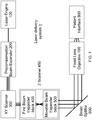
- FIG. 1 illustrates a laser delivery system 1.
- eye trackers establish positional references of the eye by visual clues such an identification of the center of the iris by imaging and image processing algorithms, typically on the surface of the eye.
- existing eye trackers recognize and analyze features in a two-dimensional space, lacking depth information, since the surgical procedures are performed on the cornea, the outermost layer of the eye. Often, the cornea is even flattened to make the surface truly two dimensional.
- the situation is quite different when focusing a laser beam in the lens, deep inside the eye.
- the crystalline lens can change its position, shape, thickness and diameter during accommodation, not only between prior measurement and surgery but also during surgery.
- Attaching the eye to the surgical instrument by mechanical means can also change the shape of the eye in an ill-defined manner.
- Such attaching devices can include fixating the eye with a suction ring, or aplanating the eye with a flat or curved lens.
- the movement of the patient during surgery can introduce additional changes. These changes can add up to as much as a few millimeters of displacement of visual clues within the eye. Therefore, mechanically referencing and fixating the surface of the eye such as the anterior surface of the cornea or limbus are unsatisfactory when performing precision laser surgery on the lens or other internal portions of the eye.
- laser delivery system 1 can be combined with an imaging system, as described in co-pending application serial number US Patent Application 12/205,844 to R.M. Kurtz, F. Raksi and M. Karavitis .
- the imaging system is configured to image portions of a surgical region to establish three dimensional positional references based on the internal features of the eye. These images can be created before the surgery and updated in parallel with the surgical procedure to account for individual variations and changes. The images can be used to direct the laser beam safely to the desired location with high precision and control.
- the imaging system can be an Optical Coherence Tomography (OCT) system.
- OCT Optical Coherence Tomography
- the imaging beam of the imaging system can have a separate imaging optical path, or an optical path partially or fully shared with the surgical beam. Imaging systems with a partially or fully shared optical path reduce the cost and simplify the calibration of the imaging and surgical systems.
- the imaging system can also use the same or a different light source as the laser of the laser delivery system 1.
- the imaging system can also have its own beam scanning subsystems, or can make use of the scanning subsystems of the laser delivery system 1.
- the laser delivery system 1 can be also implemented in combination with a visual observation optics.
- the observation optics can help the operator of the surgical laser to observe the effects of the surgical laser beam and control the beam in response to the observations.
- an additional tracking laser may be employed operating at visible frequencies.
- the visible tracking laser maybe implemented to track the path of the infrared surgical laser.
- the tracking laser may be operated at a low enough energy not to cause any disruption of the target tissue.
- the observation optics may be configured to direct the tracking laser, reflected from the target tissue, to the operator of the laser delivery system 1.
- the beams associated with the imaging system and the visual observation optics can be coupled into the laser delivery system 1 e.g. through a beam splitter/dichroic mirror 600.
- the present application will not discuss extensively the various combinations of the laser delivery system 1 with the imaging, observational and tracking systems.
- FIG. 1 illustrates a laser delivery system 1, which includes a Laser Engine 100, a Precompensator 200, an XY Scanner 300, a First Beam Expander block 400, a Movable Beam Expander block 500, a Beam Splitter/dichroic mirror 600, an Objective 700 and a Patient Interface 800, wherein the First Beam Expander block 400 and the Movable Beam Expander block 500 will be jointly referred to as Z Scanner 450.
- the Z direction is the direction essentially along the optical path of the laser beam, or along the optical axis of the optical element.
- the directions transverse to the Z direction are referred to as XY directions.
- the term transverse is used in a broader sense to include that in some implementations the transverse and Z directions may not be strictly perpendicular to each other. In some implementations the transverse directions can be better described in terms of radial coordinates. Thus the terms transverse, XY, or radial directions denote analogous directions in the described implementations, all approximately (but necessarily precisely) perpendicular to the Z direction.
- the Laser Engine 100 1. The Laser Engine 100
- the laser engine 100 can include a laser to emit laser pulses with predetermined laser parameters. These laser parameters may include pulse duration in the 1 femtosecond to 100 picosecond range, or within the 10 femtosecond to 10 picosecond range, or in some embodiments the 100 femtosecond to 1 picosecond range.
- the laser pulses can have an energy per pulse in the 0.1 microJoule to 1000 microJoule range, in other embodiments in the 1 microJoule to 100 microJoule range.
- the pulses can have a repeat frequency in the 10 kHz to 100 MHz range, in other embodiments in the 100 kHz to 1 MHz range.
- laser parameters which fall within a combination of these range limits, such as a range of pulse duration of 1-1000 femtosecond.
- the laser parameters for a particular procedure can be selected within these wide ranges e.g. during a pre-operational procedure, or based on a calculation which is based on certain data of the patient, such as his/her age.
- Examples of the laser engine 100 can include Nd:glass and Nd:Yag lasers, and other lasers of a wide variety.
- the operating wavelength of the laser engine can be in the infrared or in the visible range. In some embodiments the operating wavelength can be in the 700 nm - 2 micron range. In some cases the operating wavelength can be in the 1.0-1.1 micron range, e.g. in infrared lasers based on Yb or Nd.
- the laser parameters of the laser pulses may be adjustable and variable.
- the laser parameters may be adjustable with a short switch time, thus enabling the operator of the surgical laser delivery system 1 to change laser parameters during a complex surgery. Such a change of parameters can be initiated in response to a reading by a sensing or imaging subsystem of the laser delivery system 1.
- Other parameter changes can be performed as part of a multi-step procedure during which the laser delivery system may be first used for a first surgical procedure, followed by a second, different surgical procedure. Examples include first performing one or more surgical steps in a region of a lens of an eye, such as a capsulotomy step, followed by a second surgical procedure in a corneal region of the eye. These procedures can be performed in various sequences.
- High repetition rate pulsed lasers operating at a pulse repetition rate of tens to hundreds of thousands of shots per second or higher with relatively low energy per pulse can be used for surgical applications to achieve certain advantages.
- Such lasers use relatively low energy per pulse to localize the tissue effect caused by the laser-induced photodisruption.
- the extent of the disrupted tissue can be limited to a few microns or a few tens of microns. This localized tissue effect can improve the precision of the laser surgery and can be desirable in certain surgical procedures.
- many hundreds, thousands or millions of pulses can be delivered to a sequence of spots which are contiguous, nearly contiguous, or are separated by controlled distances. These implementations can achieve certain desired surgical effects, such as tissue incisions, separations or fragmentation.
- the parameters of the pulses and the scan pattern can be selected by various methods. For example, they can be based on a preoperative measurement of the optical or structural properties of the lens.
- the laser energy and the spot separation can also be selected based on a preoperative measurement of optical or structural properties of the lens or on an age-dependent algorithm.
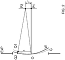
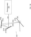
- FIG. 2 illustrates that the wavefront of the laser beam can deviate from an ideal behavior in several different ways and for several different reasons. A large group of these deviations are called aberrations. Aberrations (and the other wavefront distortions) displace real image points from the ideal paraxial Gaussian image points.
- FIG. 2 illustrates wavefronts of light exiting through an exit pupil ExP.
- the undistorted spherical wavefront G emanates from the pupil and converges to a point P1 at the center of curvature of the wavefront G. G is also called the Gaussian reference sphere.
- An aberrated wavefront W deviates from G and converges to a different point P2.
- the aberration ⁇ W depends on the coordinates both at the exit pupil as well as at the focal plane. Therefore, this aberration ⁇ W can be also thought of as a correlation function: it represents that the set of points whose image converges to P2, removed from P1 on the optical axis by r', are located on a surface W , which deviates from the reference sphere G by an amount of ⁇ W at the radial distance r at the Exit pupil ExP.
- r' is the radial coordinate of the image point P2 in the focal plane and r is the radial coordinate of point Q1 at the pupil.
- the angular dependence is represented by ⁇ , the spherical angle.
- n 2p + m is a positive integer and 2l + m a nm are the expansion coefficients of the aberrated wavefront W.
- i 2l + m + n.
- the actual relations between these primary aberrations and the 2l + m a nm aberration coefficients are documented in the literature.
- the aberration coefficients a nm all have the dimension of length and represent the maximum value of the corresponding aberration at the exit pupil.
- the spherical aberration is characterized by the aberration coefficient a 40 .
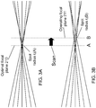
- FIGS. 3A-C illustrate a second measure of aberrations.
- the laser delivery system 1 which was configured to focus a beam at a focal plane 210 at depth A, can cause a spherical aberration if it is operated to focus the beam at an operating focal plane 211 at depth B instead.
- Such a situation can occur, for example, during a three dimensional scanning procedure, when the focal point of the laser beam is moved from focal plane 210 to focal plane 211.
- FIG. 3A illustrates the case when the laser delivery system 1 focuses the rays to their optimal focal plane 210.
- the rays pass through a spot at the optimal focal plane 210 (a "focal spot") of very narrow radial extent, or radius, r f (A).
- This radial extent r f (A) can be greater than zero for a variety of reasons, such as the diffraction of the light beam.
- the radius of the focal spot can be defined in more than one ways.
- a common definition of r f (A) is the minimal radius of the light spot on a screen as the screen's position is varied along the axial, or Z, direction. This Z depth is often called the "point of least confusion". This definition is further refined in relation to FIG. 3C .
- FIG. 3B illustrates the case when the laser delivery system 1 scans the focus by some distance, such as a few millimeters, off the optimal focal plane 210, to an operating focal plane 211.
- the rays pass through a focal spot of a radius r f (B) larger than r f (A) , causing a spherical aberration.
- Mathematical formulae of various accuracy have been developed connecting the aberration coefficients a nm and the focal spot radius r f .
- the focal spot radius r f is an experimentally more accessible measure to quantify the aberrations than the a mn aberration coefficients.
- FIG. 3C illustrates a more quantitative definition of the focal spot radius r f .
- FIG. 3C illustrates the energy contained in a spot of radius r , measured from a centroid of the beam.
- a widely accepted definition of the focal spot radius r f is the radius, within which 50% of the beam's energy is contained.
- LIOB laser induced optical breakdown
- Surgical procedures based on laser induced optical breakdown can have higher precision and efficiency and smaller undesirable effects if the laser beam's energy is deposited in a well or sharply defined focal spot.
- LIOB is a highly nonlinear process with an intensity (plasma-) threshold: typically, tissue exposed to a beam with intensity higher than the plasma threshold turns into plasma, whereas tissue exposed to a beam with intensity below the plasma threshold does not undergo the plasma transition. Therefore, a broadening of the focal spot by aberration reduces the fraction of the beam which achieves intensity at the focal plane higher than the plasma threshold and increases the fraction of the beam whose intensity remains below the threshold. This latter fraction of the beam is not absorbed effectively by the target tissue and continues to propagate through the eye tissue, in most cases to the retina, potentially causing undesirable retinal exposure.
- the focal plane is typically scanned, or shifted, in the Z direction (along the optical axis) only by about 0.6 mm from its optimal or nominal depth, since the thickness of the cornea is essentially 0.6 mm, in rare case thicker but still does not exceed 1 mm.
- the Strehl ratio S of a system can be defined referring to a beam which emanates from a point source, as a peak intensity of the beam at the focal plane of the system divided by the theoretical maximum peak intensity of an equivalent perfect imaging system, which works at the diffraction limit. Equivalent definitions are also known in the literature and are within the scope of the definition of the Strehl ratio S.
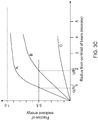
- a fourth definition of the aberrations is ⁇ , a root-mean-square, or RMS, wavefront error which expresses the deviation ⁇ W of the aberrated wavefront W from the undistorted wavefront G of FIG. 2 , averaged over the entire wavefront at the Exit pupil ExP.
- ⁇ is expressed in units of the wavelength of the beam, making it a dimensionless quantity.
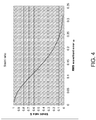
- FIG. 4 illustrates that for relatively small aberrations ⁇ and S are related by the following empirical formula: S ⁇ e ⁇ 2 ⁇ 2 regardless of the type of aberration, where e is the base of natural logarithm.
- aberration measure can refer to any one of these measures, or their equivalents.
- increasing aberration is captured by an increase of the aberration coefficients a mn , focal spot radius r f and RMS wavefront error ⁇ , but by a decrease of the Strehl ratio S.
- the surgical laser system focuses the laser beam in an ocular tissue at different depths below its surface.
- the numbers of this example can be analogous to the effects of adding a plan parallel plate of thickness equal to the scanned depth near the focal plane of the system, and carrying out the calculation for salty water.
- the surface of the tissue introduces aberrations in the beam, characterized by Equations (2) and (3).
- LASIK surgeries typically form flaps in a depth of 0.1 mm. At these depths, the Strehl ratio S is reduced to about 0.996, only a small decrease. Even at 0.6 mm depth, approximately at the posterior surface of the cornea, S is about 0.85. While this is a non-negligible decrease of peak intensity, but still can be compensated by adjusting the laser beam intensity.
- the beam intensity is reduced considerably below the plasma-threshold, and thus the beam is unable to generate LIOB.
- This drastic loss of peak intensity cannot be compensated by increasing the laser power without undesirable effects such as a serious over-exposure of the retina or excessively increased bubble size.
- Table 1 illustrates the spherical aberration a 40 , corresponding to the just-described Strehl ratios. Visibly, the spherical aberration increases approximately linearly with the tissue-depth, whereas the Strehl ratio S behaves in a non-linear manner: Table 1 Depth in tissue [mm] Spherical aberration a 40 [micron] Strehl ratio S 0 0.00 1.000 0.1 -0.04 0.996 0.6 -0.24 0.856 5 -2.00 0.054 10 -3.99 0.041
- the focal plane is often scanned across the entire depth of the lens, which can be as much as 5mm. Moreover, in integrated cornea-lens systems, the total scanning depth can extend from the cornea to the posterior surface of the lens, about 10 mm.
- the optimal focal plane can be chosen to lie halfway in the depth-scanning range and the laser beam maybe scanned in a plus/minus 5mm depth range. In this case r f (C) can be reduced to 10 microns.
- some embodiments include the Precompensator 200 to precompensate the spherical aberration and improve the aberration measures. These aberrations can be developed in the target tissue, or along a portion of the optical pathway within the laser delivery system 1, or along the entire optical pathway.
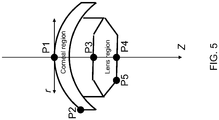
- FIG. 5 illustrates (not to scale) that, since the aberration measures r f (C) , a 40 , S and ⁇ depend on the focal spot's depth z and its radial distance r from the optical axis, in what follows when it is described that an aberration measure assumes a value, this will refer to the aberration measure assuming the described value at some selected reference points.
- P1 is a typical point for a centrally located corneal procedure
- P2 is typical for peripheral corneal procedures
- P3 is related to the anterior region of the lens
- P4 is related to the posterior of the lens
- P5 is a peripheral lens reference point.
- Other reference points can be adopted to characterize the aberrations of a laser delivery system as well.
- an aberration measure can refer to the aberration measure averaged over the operational wavefront, or illuminated area.
- the aberration measures can be determined in several different ways.
- a wavefront of the laser beam can be tracked in a computer-aided design (CAD) process through a selected section of the optical pathway, such as a model of the target tissue, or a section of the laser delivery system 1.
- CAD computer-aided design
- the aberration of the laser beam can be measured in an actual laser delivery system, or a combination of these two procedures.
- the precompensation, introduced by the Precompensator 200 may be selected by determining, calculating or measuring an aberration measure along a selected portion of the optical pathway, which may include the target tissue itself and then determining an amount of precompensation which is needed to compensate a preselected portion of the determined/calculated/measured aberration.
- the Precompensator 200 can correct, or precompensate, the spherical aberration efficiently, because the spherical aberrations dominantly affect axial rays.
- Other types of aberrations such as transverse aberrations, astigmatism and coma, affect non-zero angle rays as well as field rays, including rays being offset from the optical axis.
- the laser beam, generated by the laser engine 100 is an essentially axial beam
- the various blocks in the optical pathway, most notably the XY Scanner 300 transform this axial beam into a non-zero angle beam, having field rays.
- the field rays of the beam can develop several different aberrations.
- This emergence of different aberrations poses great design challenges because (i) the optimization of the beam may require compensating several of the aberrations, and (ii) the different types of aberrations are not independent from each other. Thus, compensating one type of aberration typically induces unwanted other types of aberration.
- the spherical aberrations are typically compensated only to a limited degree and at the expense of introducing other types of unwanted aberrations.
- embodiments of the present laser delivery system 1 can have the Precompensator 200 before the XY Scanner 300. This design allows the Precompensator 200 to precompensate a spherical aberration without introducing other types of unwanted aberrations.
- Some implementations can even exploit the above mentioned interdependence of the on-axis and the off-axis aberrations by introducing an on-axis precompensation by the Precompensator 200 to precompensate an off-axis aberration, caused by a subsequent segment of the laser delivery system or the target tissue.
- FIGS. 6A-B illustrate schematically an idealized operation of the Precompensator 200.
- FIG. 6A illustrates a laser delivery system 1 without a precompensator.
- an optical pathway segment 301 can introduce some level of spherical aberration. This is shown by an undistorted wavefront entering the optical pathway segment 301 and a wavefront with aberration leaving the optical pathway segment 301.
- This segment can be any segment of the optical pathway, such as a portion of the target tissue, or the entire target tissue, or a portion of the pathway within the laser delivery system 1.
- FIG. 6B illustrates that the Precompensator 200 can introduce a compensating (or complementary) distortion of the wavefront. This precompensated wavefront then enters the optical pathway segment 301, causing it to output a wavefront with reduced distortion, or even without distortion.
- Some existing systems do not have a dedicated compensator at all.
- Other systems may compensate the spherical aberration only in a distributed manner by the lenses of lens groups which have other functions as well and are positioned after the XY scanner.
- the parameters of the lenses are chosen as a result of making compromises between different functionalities, leading to limitations on their performance.
- embodiments of the laser delivery system 1 can have the dedicated Precompensator 200 disposed before the XY Scanner 300.
- the Precompensator 200 is the first optical unit, or lens group, which receives the laser beam from the laser engine 100. Since because of its location the laser beam reaches the Precompensator 200 without developing non-zero angle rays or field rays (which could be caused by the XY Scanner 300), these embodiments can achieve a high level of precompensation.
- the precompensation is also efficient because it is a primary function of the Precompensator 200 and thus design compromises can be kept very limited, as opposed to existing systems, which compensate with lenses serving additional functions.
- the spherical aberration of a compound lens system is approximately the sum of spherical aberrations of individual components. Therefore, in some implementations of the laser delivery system 1, an unwanted amount of spherical aberration can be precompensated by designing the Precompensator 200 to introduce an equal amount of aberration, but with the opposite sign.
- installing the Precompensator 200 can increase the Strehl ratio from a value S ⁇ S(precomp) of the non-precompensated laser delivery system 1 to a value S>S(precomp) for the precompensated laser delivery system 1.
- S(precomp) can be 0.6, 0.7, 0.8 or 0.9, for example.
- this Strehl ratio S here and below can refer to any one of the Strehl ratios S (P1), ... S (P5) at the five reference points P1-P5 above, or to the Strehl ratio at some other predetermined reference points, or to an average of the Strehl ratios over the five reference points, or to an average over the operational wavefront.
- the Strehl ratio can refer to the entire laser delivery system 1, receiving the laser beam from Laser Engine 100, ending with the Objective 700 and forming the focal spot in an ophthalmic target tissue.
- the term can refer to other targets, including air.
- the term can refer to a subsystem of the laser delivery system 1.
- S(precomp) can be 0.6, 0.7, 0.8, or 0.9, for example.
- S(precomp) can be 0.6, 0.7, 0.8, or 0.9, for example.
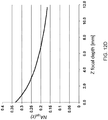
- NA NA(precomp)
- the value of NA(precomp) can be 0.2, 0.25, 0.3 or 0.35, for example.
- adding the Precompensator 200 to a laser delivery system 1 without one can decrease the focal spot radius r f in a target tissue from a non-precompensated value above r f (precomp) to a precompensated value below r f (precomp), corresponding to the laser delivery system 1 with the Precompensator 200.
- r f (precomp) can be 2, 3 or 4 microns.
- installing the Precompensator 200 can increase the RMS wavefront error from a value ⁇ > ⁇ (precomp) of the non-precompensated laser delivery system 1 to a value ⁇ (precomp) for the precompensated laser delivery system 1.
- ⁇ (precomp) can be 0.06, 0.07, 0.08 or 0.09, all in units of the wavelength of the laser beam, for example.
- installing the Precompensator 200 can increase the spherical aberration coefficient from a value a 40 >a 40 (precomp) of the non-precompensated laser delivery system 1 to a value a 40 >a 40 (precomp) for the precompensated laser delivery system 1.
- a 40 (precomp) can be 2, 3, or 4 micrometers, for example.
- installing the Precompensator 200 into a non-precompensated laser delivery system 1 can reduce at least one of the following aberration measures: the RMS wavefront error ⁇ , the spherical aberration measure a 40 and the focal spot radius r f from a non-precompensated value by at least a precompensation percentage P(precomp), or increase a Strehl ratio S by at least the precompensation percentage P(precomp).
- P(precomp) can be 10%, or 20%, or 30%, or 40%, for example.
- any one of these aberration measures can belong to any one of the reference points P1, ... P5, or to some other predetermined reference points, or to an average of values at reference points, or can be an average over the wavefront.
- the Precompensator 200 can compensate non-spherical aberrations, such as first, or higher order aberrations as well. In some cases it can perform precompensation of off-axis rays too.
- the Precompensator 200 precompensates other types of aberrations, while not increasing the RMS wavefront error by more than 0.075, or by keeping the Strehl ratio above S(precomp), having a value of e.g. 0.8.
- Position actuators can move the movable lens or lenses, changing the distance between some of the lenses of the Precompensator 200.
- the movable lens of the Precompensator 200 can move the focal plane or spot of the laser delivery system 1 along the optical axis by 0.3-4.0 mm. In some other implementations, by 0.5-2.0 mm.
- S(movable) can be 0.6, 0.7, 0.8 or 0.9.
- the movable lens can be moved to vary the Strehl ratio S in the range 0.6-0.9. In other implementation in the range 0.70-0.85.
- the Precompensator 200 is located before the XY Scanner 300 or other beam expanders, the beam radius is still small. Therefore, the movable lens can be small. And since the movable lens is small, the position actuators can move it very fast, allowing for a very quick changing of the focal depth. This feature speeds up the depth scanning, or Z scanning in these embodiments and can make the Z scanning speed comparable to the typically faster XY scanning speed.
- the aberrations are compensated dominantly by optical means, such as lenses.
- the presently described movable lens Precompensator 200 can utilize the fast movable lens or lenses to carry out this function well.
- the movable lens or lenses can be moved with a sufficiently high speed so that the aberrations associated with the XY scanning get compensated to a desired level.
- FIG. 7A illustrates that this aspect can be useful when a transverse surgical cut 206 is performed essentially tracking the contact surface of a planar or curved patient interface 208.
- the speed of the small movable lens makes it possible that the Z scanning is performed at the speed required by the XY scanning, forming the desired curved cut.
- a curvature, or radius, of the curved cut, or curved target line can be smaller than 1 mm, 10 mm, and 100mm.
- FIG. 7B illustrates another useful aspect of a high Z scanning speed.
- the focal plane of most optical systems is somewhat curved. If it is desired to create an essentially straight transversal cut, which therefore does not track the curvature of the focal plane, the focal depth needs to be continuously re-adjusted, synchronously with the fast transverse XY scanning to compensate for the curvature of the focal plane. For example, for radial cuts or planar cuts with a raster scan pattern the change of the radial, or XY coordinate, can be very fast. In these procedures a fast Z scanning speed can help forming the desired straight cut.
- the high Z scanning speed can be also useful to perform some surgical procedures fast, such as corneal procedures.
- the movable lens Precompensator 200 can change the depth of the focal spot of the laser delivery system with an axial speed at least 5% of the maximum transversal scanning speed of the focal spot. In some implementations with an axial speed at least 10% of the maximum transversal scanning speed of the focal spot. In other embodiments with an axial speed at least 20% of the maximum transversal scanning speed of the focal spot.
- the movable lens Precompensator 200 can change the Z coordinate of the focal spot by 0.5 - 1 millimeter in a Z scanning time.
- this Z scanning time can be in the range of 10-100 nanoseconds, 100 nanoseconds - 1 millisecond, 1 millisecond - 10 milliseconds and 10 milliseconds - 100 milliseconds.
- the movable lens of the lens group is movable in a Z moving range to reduce a first aberration measure by at least a movable percentage P(movable).
- the first aberration measure can be a spherical aberration coefficient a 40 , an RMS wavefront error ⁇ , and a focal spot radius r f ; and the movable percentage P(movable) can be 10%, 20%, 30% and 40%.
- the movable lens of the lens group is movable in a Z moving range to increase a Strehl ratio S by at least a movable percentage P(movable), which can be 10%, 20%, 30% and 40%.
- the movable lens Precompensator 200 is capable of changing a numerical aperture NA of the laser delivery system 1, a Z depth of the focal spot, any one of the aberration measures and a beam diameter essentially independently by moving the movable lens.
- moving the movable lens is capable of varying any one of these four characteristics of the laser delivery system 1 without changing the other two characteristics.
- Precompensator 200 Some of the functions of the Precompensator 200 are sometimes referred to as beam conditioning or beam expanding. Correspondingly, in some existing systems blocks with analogous functions are referred to as beam conditioner or beam expanders.
- the Precompensator 200 includes just one lens to achieve the above functionalities.
- the Precompensator 200 includes two to five lenses to achieve the above functionalities.
- FIG. 8A illustrates a three lens embodiment of Precompensator 200, including lens 221, lens 222 and lens 223.
- FIG. 8B illustrates a three lens embodiment of movable lens Precompensator 200', including lens 221', movable lens 222' and lens 223'.
- FIG. 8C illustrates a four lens embodiment of Precompensator 200", including lenses 231-234.
- FIG. 8D illustrates a four lens embodiment of movable lens Precompensator 200''', including lens 231', movable lens 232', lens 233' and lens 234'.
- Tables 2-4 illustrate various three lens implementations of the Precompensators 200 and 200' of FIGS. 8A-B.
- Embodiments of the Precompensator 200 can be implemented using thin lenses. Therefore, they can be described in terms of refractive powers of the individual lenses and their distances from the next lens.
- Table 2 illustrates a three fixed lens embodiment of Precompensator 200, also shown in FIG. 8A .
- column 1 shows the lens number
- Table 3 illustrates a possible implementation of Precompensator 200' with two movable lenses 222' and 223', as in FIG. 8B , showing lens spacings diA and diB in two configurations A and B in columns 3 and 4.
- the lens spacings di can vary continuously between diA and diB.
- Table 4 illustrates that in various implementations the above parameters Di and di can assume values in broad intervals, depending on a large number of design considerations, such as different beam sizes and available space.
- Some of the parameters of these implementations can be connected to the embodiments of Tables 2-3 by scaling: the refractive powers with a scaling factor a , and the distances with a corresponding scaling factor 1 / a.
- the refractive powers can be additionally modified by tolerance factors t1 trough t3 to allow for differences in tolerances and design implementations.
- the scaling factor a can be in a range of 0.3 to 3
- the tolerance factors t1, t2, and t3 can be in a range of 0.8 to 1.2.
- Table 5 illustrates various four lens implementations of the Precompensator 200", wherein the lenses 231, 232, 233 and 234 are fixed, as shown in FIG. 8C .
- Table 6 illustrates a four lens implementation of the Precompensator 200''' of FIG. 8D , with one movable lens 232'.
- the parameters of the four lens Precompensators 200" and 200''' can assume values in broad ranges. Parameters of some of these implementations again can be related to each other by scaling factors a , 1 / a, t1, t2, t3, and t4, respectively, in analogy to Table 4.
- the scaling factor a can be in the range of 0.2 to 5 and the tolerance factors t1, ... t4 can be in a range of 0.7 to 1.3.
- the moving lens can change one of the laser system's characteristics essentially independently. These parameters include the Z focal depth, the numerical aperture NA, any one of the aberration measures, and a diameter of the exit beam. For example, these implementations allow the operator to change e.g. the numerical aperture of the laser delivery system 1, without changing e.g. the Z focal depth.
- the Precompensator 200 has two independently moving elements. Such implementations allow the operator to independently control two characteristics of the laser beam, such as e.g. the beam diameter and the numerical aperture NA, while keeping the aberrations fixed.
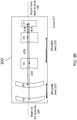
- FIG. 9 illustrates an embodiment of the laser delivery system 1', where a Z scanning functionality of various optical blocks is highlighted.
- the laser engine 100 generates a laser beam, which is received by a first Z Scanner 250.
- the first Z Scanner 250 receives the laser beam from the laser engine 100 and scans a focal point of the laser delivery system 1' over a first Z interval along an optical axis of the laser delivery system 1'.
- the beam, outputted by the first Z Scanner 250 is received by the XY Scanner 300, which scans the laser beam in a direction essentially transverse to the optical axis of the laser system.
- the outputted XY scanned laser beam is then received by a second Z Scanner 450, which scans the focal point of the laser system over a second Z interval along the optical axis of the laser system.
- the first Z Scanner 250 is configured so that the first Z interval is suitable for a corneal surgical procedure
- the second Z Scanner 450 is configured so that the second Z interval is suitable for an anterior segment surgical procedure.
- the first Z interval is within the range of 0.05-1 mm and the second Z interval is within the range of 1-5 mm.
- the first Z interval is within the range of 1-5 mm and the second Z interval is within the range of 5-10 mm.
- the first Z Scanner 250 is configured to scan the focal point over the first Z interval of 0.05 mm-1 mm in a first Z scanning time.
- the first Z scanning time can be in one of the ranges of 10-100 nanoseconds, 100 nanoseconds - 1 millisecond, 1 millisecond - 10 milliseconds, and 10 milliseconds - 100 milliseconds.
- the second Z Scanner 450 is configured to scan the focal point over the second Z interval of 1 mm - 5 mm in a second Z scanning time.
- the second Z scanning time can be in one of the ranges of 10-100 milliseconds, and 100 milliseconds - 1second.
- the first Z Scanner 250 is configured to change the numerical aperture of the laser beam by more than 10%.
- the second Z Scanner 450 is configured to change the numerical aperture of the laser beam by more than 10 %.
- the first Z Scanner 250 is configured to change the numerical aperture of the laser beam by more than 25%.
- the second Z Scanner 450 is configured to change the numerical aperture of the laser beam by more than 25%.
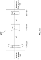
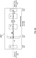
- FIG. 10 shows a summary table of the many variations of the above described elements. As shown, some implementations can have 0 Z depth scanners, 1 Z depth scanner before the XY Scanner 300, 1 Z depth scanner after the XY Scanner 300 and 2 Z depth scanners, one before and one after the XY Scanner 300.
- some implementations can have 0 NA controller, 1 NA controller before the XY Scanner 300, 1 NA controller after the XY Scanner 300 and 2 NA controllers, one before and one after the XY Scanner 300.
- the Z Scanners and NA controllers quite generally refer to a single lens or a lens group, which can modify the Z depth and the numerical aperture NA, respectively.
- these modifiers can be activated, or controlled by a single electric actuator, which makes the lenses of the modifier move synchronously to modify the NA or the Z depth of the beam.
- Both the Z Scanners and the NA controllers can be housed in the first Z Scanner 250 and the second Z Scanner 450 of FIG. 9 .
- the corresponding optical elements are distinct, in other implementations the Z Scanner and the NA controller which are housed in the same Z Scanner block 250 or 450, can share one or more lenses, movable lenses, or electric actuators.
- 0 Z scanners and one or two NA controllers operate at fixed Z depth, but can control NA during the XY scanning.
- 1 Z Scanner and 0 NA controller can perform the Z scanning.
- 1 Z Scanner and 1 or 2 NA controllers can perform, in addition to the Z scanning, a control of the NA.
- 2 Z Scanners can perform Z scanning at two speeds and also control the NA, when combined with 1 or 2 NA controllers.
- Non-lens optical elements are also used in some implementations, such as variable apertures and pupils.
- most of the illustrated 16 combinations can be further configured to precompensate a selected aberration, such as the spherical aberration.
- FIG. 10 illustrates that the various system characteristics, such as the Z depth of the beam, its numerical aperture NA and its aberration, represented by its aberration measure such as the Strehl ratio S, can be controlled or adjusted independently of each other.
- Such embodiments offer a great control and precision to the operator of laser delivery system 1.
- such double beam conditioning can be performed for other pairings of beam characteristics.
- 0, 1, or 2 aberration controllers can be paired in all possible combinations with 0, 1 or 2 beam diameter controllers.
- the list of beam characteristics includes: Z depth of the focal spot, the numerical aperture NA, the beam radius, and any aberration measure, such as the Strehl ratio S , the focal spot radius r f , the RMS wavefront error ⁇ and the spherical aberration measure a 40 .
- the XY Scanner 300 may receive the precompensated beam from the Precompensator 200, either directly of indirectly, having passed through some intermediate optical elements.
- a function of the XY Scanner 300 may be to scan the beam received from the Precompensator 200 in a direction essentially transverse to an optical axis of the laser delivery system 1.
- the "transverse" direction is not necessarily perpendicular to the optical axis, and can include any direction which makes a substantial angle with the optical axis.
- the XY Scanner 300 outputs a scanning laser beam, which, having propagated through the laser delivery system 1 and having reached the surgical region, scans in a transverse direction from zero to a maximum of an XY scanning range of 5-14 mm. In some implementations maximum of the XY scanning range is between 8 and 12 mm.
- FIG. 11A illustrates that the XY Scanner 300 can include an X scanner and a Y scanner.
- the X and the Y scanner each include one mirror: a single X scanning mirror 310 and a single Y scanning mirror 320.
- the beam deflected by the X scanning mirror 310 hits the Y scanning mirror 320 at different points depending on the orientation of the X scanning mirror 310.
- the incident beam 331 is reflected as beam 332a
- the incident beam is reflected as beam 332b.
- a pivot point of a scanning optical element can be as the point through which essentially all rays go through, having exited from the optical scanning element.
- This notion is the analogue of the focal point of non-moving refractive elements, as applied for moving optical elements, such as scanners.
- FIG. 11B illustrates an existing three mirror XY Scanner 300', where the X scanner 310 includes two mirrors 311 and 312 to address this problem. For clarity, the mirrors are shown from the side.
- X scanning mirrors 311 and 312 perform the X scanning function in a coordinated manner.
- the first X scanning mirror 311 changes its orientation from 311a to 311b
- the second X scanning mirror 312 can be rotated in a coordinated manner from 312a to 312b.
- These coordinated scanning rotations make it possible that the deflected beams 332a and 332b in the two rotational states go through a pivot point 315X, which is lifted off the X scanning mirrors.
- the X scanner pivot point 315X has been lifted from the X scanning mirror itself, its location can be adjusted.
- the X scanning mirrors are designed to place the pivot point 315X essentially onto the Y scanning mirror 320. In such designs the problem of the X scanner 310 in FIG. 11A is essentially resolved and the corresponding aberrations are much reduced.
- the entrance pupil of an optical system is the image of the aperture stop when viewed from the front of the system.
- the exit pupil is the image of the aperture stop in the image space.
- the locations of the entrance and exit pupils are often carefully adjusted.
- the exit pupil of one lens group matches the entrance pupil of the following lens group.
- the pivot point can be regarded as the exit pupil.
- this exit pupil matches the entrance pupil of the following lens group, such as the Z Scanner 450.
- the entrance pupil of that lens group may be inside the physical boundaries of the lens group, where a scanner block cannot be placed. In that case a scanner block is desirable for which the pivot point is outside the physical boundaries of the scanner block, at a location which can be arbitrarily chosen.
- FIG. 11C illustrates a four mirror design to address this problem.
- the X scanner 310 again includes two X scanning mirrors 311 and 312.
- the Y scanner also includes two Y scanning mirrors, 321 and 322.
- XY Scanner 300" removes the Y scanner pivot point 315Y from the Y scanning mirror. Accordingly, XY Scanner 300" can control the Y scanner, or output, pivot point 315Y to a predetermined location. An example is to move the Y scanning-output pivot point 315Y onto the entry pupil 340 of a subsequent lens group. In some implementations the X pivot point 315X can be also moved to the same location as well.
- XY Scanner 300" can control essentially independently (i) an angle ⁇ between the outputted scanned beam and an optical axis of the laser delivery system 1, and (ii) a location where the scanning beam impacts the entrance pupil of the subsequent optical element, characterized by a distance d from the optical axis. Because of the approximate independence of these controls, the XY Scanner 300" can provide a scanning beam with minimized aberrations, as well as can control astigmatism and coma in the peripheral regions, including the peripheral regions of the surgical region.
- XY Scanner 300''' include only one X scanning mirror 310 and one Y scanning mirror 320, each of them of the "fast steering" type.
- An individual fast steering mirror is capable of angular motion around two axes of rotation.
- a pair of these fast steering mirrors can also control the beam angle and the beam position in the plane transversal to the optical axis.
- the XY Scanner 300''' is configured to scan the laser beam over an XY scanning range whose maximum is longer than 5 millimeter and shorter than 15 millimeter at the focal plane of the laser system.
- the X pivot point generated by the first and second XY fast steering mirrors and the Y pivot point generated by the first and second XY fast steering mirrors coincide.
- ophthalmic surgical systems are configured to perform anterior segment surgery, or lens surgery by having a design which allows scanning a focal point over an interval much larger than the scanned interval in corneal procedures.
- the Z scanning is performed over a Z scanning path within the Z scanning range of 5 mm to 10 mm, or 0 mm to 15 mm.
- the term "scanning within a range of x mm to y mm" refers to a scanning path whose initial value is x mm or more and ending value is y mm or less, encompassing all scanning paths which do not extend across the entire scanning range.
- Z typically denotes an optical axis, which can be close to a geometrical axis. But the Z direction inside a target tissue, such as the eye, may not be fully parallel to the optical axis of the laser delivery system 1. Any compromise axis between these two can be also referred to as the Z direction.
- the X, Y directions are not necessarily perpendicular to the Z axis. They can refer to any direction making a substantial angle with the Z direction.
- a radial coordinate system may be more suitable to describe the scanning of the laser delivery system 1. In those implementations, the XY scanning refers to any scanning not parallel to the Z axis, parametrized by suitable radial coordinates.
- FIG. 1 illustrates that some implementations of the laser delivery system 1 achieve these challenging large Z scanning ranges by including the First Beam Expander block 400 and the Movable Beam Expander block 500 in the Z Scanner 450.
- the First Beam Expander block 400 can be a movable block or a fixed block.
- the distance between the First Beam Expander block 400 and the Movable Beam Expander block 500 can be adjusted e.g. by a position actuator.
- the aberrations increase. These aberrations are typically called “geometric aberrations", as they can be understood from tracing geometric rays, and originate from the finite extent of the lenses. These geometric aberrations can be limited by making a numerical aperture of the Z Scanner 450 smaller. As such, the geometric aberrations depend both on the Z focal depth and the numerical aperture NA.
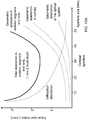
- FIGS. 12A-B illustrate the geometric and diffraction aberrations in an anterior segment of an eye as a function of the aperture size of the Z Scanner 450, characterized by one of the above aberration measures: the focal spot radius r f . Since the geometric aberration increases with the aperture size while the diffraction aberration decreases, a total aberration, defined as a sum of these two aberrations, exhibits an optimal minimum value at an optimal aberration and corresponding optimal numerical aberration NA opt .
- NA n * Sin ArTan (aperture size / (2 * focal length)), where n is the refractive index of the material in which the image is formed.
- FIGS. 12A-B also illustrate that the aberration exhibits a broad flat optimum for the typical corneal Z focal depths of 1 mm, while it exhibits a narrower, sharper minimum for Z focal depths typical for lens-surgery.
- the aberration can be also characterized by the other three aberration measures S, ⁇ , or a 40 as well, all yielding curves exhibiting an optimum.
- Any of the above four aberration measures can correspond to any of the five reference points P(1), ... P(5) described above, or can be an average taken over some or all of these reference points, or may correspond to other reference points.
- the aperture size and the corresponding NA can be adjusted to essentially the optimal numerical aperture NA opt (z), minimizing the total aberration, measured by an aberration measure.
- NA opt essentially the optimal numerical aperture NA opt (z)
- This functionality allows a strong reduction of the total aberration.
- the aberrations can be measured by one of the four aberration measures r f , S, ⁇ , or a 40 , at any one of the above five reference points P1, ... P5.
- the optimal aberration corresponds to a minimum of aberration measures r f , ⁇ , or a 40 , or a maximum of the Strehl ratio S.
- the Movable Beam Expander Block 500 can still decrease the values of the aberration measures r f , ⁇ , or a 40 by at least a P(MovableExpander) percentage, or correspondingly increase the value of the Strehl ratio S by at least a P(MovableExpander) percentage, compared to the aberration measures of an essentially identical laser system where the second block of the Z Scanner 450 is not movable and thus the numerical aperture is not adjustable.
- P(MovableExpander) can be 20%, 30%, 40%, or 50%.
- the aberration measures r f , S, ⁇ , or a 40 can be measured at any one of the five reference points P1, ... P5.
- laser systems having the Z Scanner 450 with the adjustable numerical aperture NA can increase the Strehl ratio S above 0.8, relative to essentially identical laser systems where the Z scanner does not have an adjustable numerical aperture, having a Strehl ratio S below 0.8.
- An additional design challenge is not only to minimize the total aberration at a fixed Z focal depth by adjusting the laser delivery system to its optimal aperture size and corresponding numerical aperture NA opt (z), but also to keep the system at least close to the Z dependent optimal numerical aperture NA opt (z) as the Z focal depth is scanned.
- the optimal numerical aperture decreases as the focal depth increases.
- implementations of the laser delivery system 1 have the capability of changing the numerical aperture NA(z) as a separate parameter of the Z Scanner 450, essentially independently from varying the Z focal depth itself.
- Implementations where two quantities are controlled essentially independently, as presently the Z focal depth and the numerical aperture NA, typically have a pair of control parameters to achieve this modality. Examples include the pairing of a controllable distance between the First Beam Expander block 400 and the Movable Beam Expander block 500 and a position of a movable lens in either of these blocks, which can be adjusted by a secondary optical controller. Another example includes two movable lenses in any combination in the two blocks of the Z Scanner 450. It is recalled that the First Beam Expander block 400 can be implemented as a fixed block or a movable block.
- the numerical aperture NA can be adjusted to a sequence of optimal numerical aperture values NA opt (z), yielding a sequence of optimal total aberration values at a sequence of Z focal depth as the Z focal depth is scanned.
- the optimal total aberration can be captured by the minimum of any of the above aberration measures r f , ⁇ , or a 40 , or the maximum of the Strehl ratio S.
- the Z scanning ranges can be e.g. 5-10 mm or 0-15 mm.
- Table 7 illustrates an example, where the second column describes the scanning of the Z focal depth within a Z scanning range of (-0.14 mm, 11.65 mm) in an ocular target tissue and the third column shows the corresponding values of NA opt (z). Implementations of the Z Scanner 450 are capable of adjusting the Z focal depth in this range and adjusting the numerical aperture NA to its optimal value NA opt (z) at these focal depths.
- the Z focal depth maybe scanned within a Z scanning range of 0 mm to 10 mm.
- the numerical aperture may vary within a range of 0.4 to 0.1, in some other embodiments from 0.35 to 0.15.
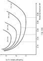
- FIG. 12C illustrates an analogous sequence of aberration curves, corresponding to a sequence of Z focal depths of 8 mm, 4 mm , 2 mm, and 0 mm, exhibiting a sequence of corresponding optimal numerical apertures N opt (z).
- FIG. 12D illustrates explicitly the optimal numerical apertures N opt (z) as a function of the corresponding Z focal depths.
- the separate adjustability of the Z focal depth and the numerical aperture NA typically requires two independently adjustable control parameters. Some implementations, however, may not offer the separate and independent adjustability of Z and NA. Instead, for every Z focal depth, these implementations adjust automatically the numerical aperture to either its optimal value NA opt (z), or at least to a vicinity of NA opt (z), without a separate NA adjusting step by an operator. For example, NA can track NA opt (z) within a P(track) percent, where P(track) can be 10%, 20%, or 30%.
- this integrated controller may only display to a user of the system that it controls the Z focal depth in the target region.
- the controller may contain a coupled aperture adjuster, which simultaneously adjusts the numerical aperture NA to track NA opt (z) without a separate tuning step performed by the user of the laser delivery system 1.
- adjusting the distance between the First Beam Expander 400 and the Movable Beam Expander 500 may perform this functionality adequately.
- a single movable lens can offer this modality.
- a combination of two adjusters may be employed.
- implementations offer a simplified control function for the operator of the laser delivery system 1. Since achieving such a single, integrated control function is a design challenge, some implementations perform these integrated control functions in combination with the other blocks, such as the Precompensator 200, the XY Scanner 300 and the Objective 700.
- the numerical aperture NA can be adjusted to a sequence of numerical aperture values at a sequence of Z focal depths along the Z scanning path within the Z scanning range to reduce the total aberration by at least a P(scan) percentage relative to laser systems whose Z Scanner 450 does not have an adjustable numerical aperture NA.
- P(scan) can be 20, 30, 40, or 50 percent.
- the total aberration can be characterized by any on of the previously introduced aberration measures r f , ⁇ , or a 40 .
- the reduction of the aberration can be characterized by a corresponding increase of the Strehl ratio S.
- the total aberration can be measured in several different ways.
- the total aberration can refer to a total aberration averaged over the Z scanning path, or to the maximum or minimal value of the total aberration along the scanning path.
- the reduction of the total aberration can refer to any one of these possibilities.
- the numerical aperture NA can be adjusted from a first value when a corneal procedure is performed to a second value when an anterior segment procedure is performed.
- the first value is in the range of 0.2-0.5 and the second value is in the range of 0.1-0.3.
- the first value can be in the range of 0.25-0.35 and the second value can be in the range of 0.15-0.25.
- the present implementation of the Z Scanner 450 is different from existing corneal laser delivery systems in several other ways, including the following.
- laser delivery systems which include an imaging sub-system or a visual observational optics sub-system, have the beams associated with either of these sub-systems coupled into the laser delivery system 1 through the mirror 600.
- the mirror 600 can be a dichroic mirror, for example.
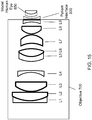
- the Objective 700 refers to the lens group which is positioned after the mirror 600 in the optical pathway.
- Tables 8-9 illustrate ranges of some relevant parameters for various embodiments of the First Beam Expander block 400 and the Movable Beam Expander block 500.
- the Beam Expander blocks each can have 2-10 lenses, in some embodiments 3-5 lenses, which are configured to carry out the above functionalities.
- Table 8 illustrates a five lens embodiment of the First Beam Expander block 400 using an industry standard convention, describing groups of thick lenses in terms of the individual surfaces.
- First Beam Expander block 400 can include lenses 411, 412, 413, 414 and 415 with parameters in the following ranges (indicated by brackets): Table 8 Surface Curvature [1/m] Distance [mm] Refractive Index n 1 (0, 1.5) (5, 25) (1.6, 1.93) 2 (22, 28) (12, 22) (1.6, 1.7) 3 (-17, -14) (0.5, 12) 1 4 (7.0, 8.5) (15, 29) (1.65, 1.8) 5 (-19, -13) (3, 14) 1 6 (14, 18) (8, 12) (1.6, 1.7) 7 (0, 9.3) (6, 12) 1 8 (-28, -21) (1, 5) (1.65, 1.75) 9 (-15, -6)
- the First Beam Expander block 400 includes, sequentially from an input side facing the XY Scanner 300: a first lens group with a positive refractive power, a meniscus lens, having a convex surface facing the input side, and a second lens, having a concave surface facing the input side.
- Table 9 illustrates a four lens embodiment of the Moving Beam Expander block 500, including lenses 511, 512, 513, and 514, with parameters in the following ranges: Table 9 Surface Curvature [1/m] Distance [mm] Refractive Index n 1 (-25, -10) (3, 7) (1.7, 1.8) 2 (-25, -28) (0, 2) 1 3 (-43, -24) (1.5, 5) (1.5, 1.62) 4 (8.5, 19.4) (26, 31) 1 5 (-6.2, -4.6) (10, 16) (1.53, 1.6) 6 (-18.4, -14.7) (34, 49) 1 7 (1.9, 4.2) (8, 14) (1.58, 1.61) 8 (-11, -9.0)
- Some implementations of the Movable Beam Expander block 500 include, sequentially from an input side facing the First Beam Expander block 400: a meniscus lens, having a concave surface facing the input side, a negative lens with a negative refractive power, and a positive lens group with a positive refractive power.
- a scale factor a having four scaled lenses, having the curvatures of the second column being multiplied by a , the distances of the third column multiplied by 1 / a, and having unchanged indices of refraction n.
- the scale factor a can assume values between 0.3 and 3.
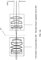
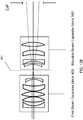
- FIGS. 13A-B illustrate embodiments of Tables 8-9 in two configurations with different distances between the First Beam Expander block 400 and the Moving Beam Expander block 500.
- FIG. 13A illustrates the case when the Movable Beam Expander block 500 is in a position relatively far from the First Beam Expander block 400.
- the beam exiting the combined assembly has (i) convergent rays, (ii) a relatively large diameter at an exit pupil ExP, (iii) a shallower Z-depth of the focal spot when a fixed focal length objective is placed near the exit pupil of the Z Scanner 450, and thus (iv) the focal spot is formed by a beam with a higher numerical aperture NA.
- FIG. 13B illustrates the case when Movable Beam Expander block 500 is closer to the First Beam Expander 400 than in the case of FIG. 13A .
- the beam has (i) divergent rays, (ii) a smaller diameter at the exit pupil ExP, (iii) a deeper Z-depth of the focal spot when a fixed focal length objective is placed at the exit pupil of the Z Scanner 450, and thus (iv) the focal spot is formed by a beam with a smaller numerical aperture NA.
- the focal spot is created by a large NA beam
- the numerical aperture NA decreases.
- the relative change in the numerical aperture NA can be optimized by optimizing the location of the exit pupil ExP of the Beam Expander blocks 400 and 500 and the location of the entrance pupil of the focusing Objective 700.
- the numerical aperture NA can be extensively adjusted with or without the Precompensator 200.
- the numerical aperture NA can be adjusted by controlling the Precompensator 200, the First Beam Expander block 400 or the Movable Beam Expander block 500, or by controlling these blocks in combination.
- the actual choice of implementation in practice depends on other higher level system level requirements, such as scanning range, scanning speed, and complexity. Implementations with other numerical ranges can also be configured to perform some or all of the above described functionalities.
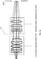
- FIG. 14 illustrates a further aspect of the Z Scanner 450.
- Three different characteristic beams are shown, emanating from an exit pivot point PP(XY) of the XY Scanner 300.
- all three characteristic beams are focused into an entrance pivot point PP(O) of the Objective 700 by the Z Scanner 450.
- the position of PP(O) can be adjusted e.g. by moving the Movable Beam Expander 500.
- laser delivery systems which generate a pivot point PP(O) located off the mirrors of the XY Scanner 300 have useful features e.g. in embodiments where the PP(O) pivot point falls inside the Objective 700.
- the XY Scanner 300 has an exit pivot point PP(XY) farther than the distance to the Z Scanner 450.
- the Z Scanner 450 only modifies the exit pivot point PP(XY) of the XY Scanner 300 into the entrance pivot point PP(O) of the Objective 700.
- the laser beam outputted by the Z Scanner 450 is deflected by the Beam Splitter/Dichroic Mirror 600 onto the Objective 700. Through this mirror 600 various auxiliary lights can also be coupled into the laser delivery system 1.
- the auxiliary light sources can include light associated with an optical coherence tomography imaging (OCT) system, an illumination system and a visual observational block.
- OCT optical coherence tomography imaging
- the Objective 700 can provide a shared optical pathway for an XYZ scanned laser beam, propagating from the laser engine 100 through the XY Scanner 300 and the Z Scanner 450, and the auxiliary light into the surgical target region.
- the Objective 700 may include objective lens groups.
- the lenses of the objective lens groups do not move relative to each other. As such, while the Objective 700 is an integral part of the Z scanning functionality, it does not contribute to the Z scanning in a variable or dynamic manner. In these implementations no lens position is adjusted in the Objective 700 to move the Z focal depth of the focal spot.
- Implementations of the Objective 700 can control at least one of a spherical aberration, coma, and higher order aberrations of the surgical pulsed laser beam.
- implementations of the Objective 700 use achromatized lens groups.
- the wavelength of the auxiliary light can be e.g. in the range of 0.4 micron to 0.9 micron, and the wavelength of the surgical light can be in the 1.0-1.1 micron range.
- Implementations of the Objective 700 keep the chromatic aberrations below a predetermined value throughout the range of wavelengths of the used lights, such as 0.4 micron to 1.1 micron in the above example.
- the weight or mass of the Objective 700 is an important consideration.
- the objective is in mechanical contact with the eye of the patient. As such, it exerts pressure on the eye. This pressure can distort the eye from its relaxed configuration, making it more difficult to select targets and direct the surgical laser beam accurately.
- the objective can move with the smallest resistance in response to the patient's movement.
- the weight of the objective can be statically balanced with a spring system or counterbalance, these measures may not reduce the dynamic or inertial forces. In fact, these forces may be increased by such measures. All of these considerations point toward the usefulness of reducing the weight or mass of the Objective 700.
- the paper also assigned a probability of injury, from (ii) low, representing a few percent chance, to medium, representing an about 50% chance, to high, referring to a near certainty of injury.
- the paper further classified (iii) the impact scenarios according to the shape of the impacting object, categorizing according to total impacting energy and impacting energy normalized by the impact area.
- the Objective 700 can be mounted on a vertical sliding stage to provide a safe and reliable docking of the laser delivery system 1 by a gantry to the eye. Such designs ease precision and force requirements on the gantry because the vertical gantry accommodates the Objective 700 to be positioned within the vertical travel range. Further, once the eye is docked, these designs allow the eye to move vertically relative to laser source 100 without breaking the attachment of the eye to the laser delivery system 1. These movements may occur due to movement of the patient or movement of the surgical bed. A vertical travel range of 20 to 25 mm of the Objective 700 mitigates effectively and safely against gantry forces and patient motion within this range.
- a design consideration also influences the critical masses in the sense that the ("optical") mass of the optical elements of the Objective 700, such as the glass lenses alone in the objective lens groups define a lower bound on the mass of the entire objective, as there are numerous ways to reduce the mass of the housing and the control systems of the objective, while it is much harder to reduce the mass of the lenses. In present systems the total mass of the objective can be two-three times the "optical" mass of the lenses alone.
- a mass of various embodiments of the Objective 700 can fall in any of the above four mass ranges: 0-400 grams, 400-750 grams, 750-1,350 grams, and 1,350-3,300 grams.
- the mass can be either the optical or the total mass.
- the lenses in an implementation of the Objective 700 can have a mass of less than 130 grams. It is feasible to mount these lenses in a precision metal housing for a total assembly mass of 400 grams.
- Embodiments of the Objective 700 achieve such a remarkable mass reduction to below 400 grams, 750 grams, 1,350 grams and 3,300 grams by removing the Z scanning functionality to the separate Z Scanner 450, housing it in a separate functional or mechanical housing.
- functional or mechanical housing refers to the fact that overall, non-functional design considerations may result in disposing the separate Z Scanner 450 into the same general container as the Objective 700, but such a general container does not serve an optical function or mechanical purpose.
- a mass of the Objective 700 can be reduced by a P(mass) percentage in comparison to analogous objectives, which perform at least some of the dynamic Z scanning functionality by adjusting an optical characteristic of the Objective 700.
- Such characteristic can be the entire Z Scanner 450 being integrated into the Objective 700, or the Movable Beam Expander block 500 being integrated into the Objective 700, or one or more movable scanning lens being integrated into the Objective 700.
- P(mass) can be 10%, 50%, or 100%.
- FIG. 14 Another related aspect of the Objective 700 and the corresponding design of the surgical laser system 1 was described in relation to FIG. 14 , where it was shown that embodiments of the Z Scanner 450 can focus the XYZ scanned laser beam onto the objective's entrance pivot point PP(O).
- Embodiments, which have the entrance pivot point PP(O) inside the Objective 700 have a much-reduced beam radius rb over a large fraction of the optical pathway, as the beam converges towards this internal pivot point PP(O).
- a beam with a reduced beam radius rb can be controlled by smaller lenses, resulting in significant reduction of the overall mass of the Objective 700.
- Implementations of the Objective 700 include a first lens group, to receive the surgical pulsed laser beam from the Z Scanner 450, and a second lens group, to receive the surgical pulsed laser beam from the first lens group and to focus the surgical laser beam onto a target region.
- Table 10 illustrates the Objective 700 of FIG. 15 in more detail via surfaces 1 trough 16.
- the Objective 700 has nine lenses L1-L9 and interfaces with the Patient Interface 800 via surface 17.
- the brackets indicate the ranges the corresponding parameters can assume.
- (Surfaces 1 and 2 define a doublet of lenses L1/L2 and surfaces 8 and 9 define a doublet of lenses L5/L6, hence the 16 surface instead of 18.)
- Table 10 Surface Curvature [1/m] Distance [mm] Index of refraction n 1 (-1.5, 4.5) (1, 6) (1.7, 1.9) 2 (7.8, 45) (6.4, 13) 1.56, 1.8) 3 (-4.2, 3.2) (0, 3.2) 1 4 (22, 36) (10.5, 14) (1.47, 1.62) 5 (-10, 5) (0, 6.8) 1 6 (-27.2, -12.6) (8.0, 11.6) (1.58, 1.63) 7 (-30.3, 2.5) (0, 6.7) 1 8 (-3.1, 18.9) (4.0, 8.3) (1
- the Objective 700 can be described in terms of lens groups.
- the Objective 700 can include a first lens group, to receive the XYZ scanned laser beam from the Z Scanner 450, and a second lens group, to receive a laser beam from the first lens group.
- the second lens group can include a first lens with an index of refraction in the range of 1.54 to 1.72, an entry surface with a curvature in the range of 37.9 to 65 1/m and an exit surface with a curvature in the range of -15.4 to 5.2 1/m.
- the second lens group can also include a second lens, separated from the first lens by a distance in the range of 0 to 6.5 mm, with an index of refraction in the range of 1.56 to 1.85, an entry surface with a curvature in the range of -55.1 to -21.8 1/m and an exit surface with a curvature in the range of 11.4 to 26.8 1/m.
- the Objective 700 can output the laser beam onto the patient interface 800 through the second lens.
- an effective focal length of the Objective 700 is less than 70 mm.
- a distance from the Objective 700 to the patient interface 800 is less than 20 mm.
- a curvature of a focal plane of the laser delivery system 1 is larger than 20 1/m.
- the parameters of the subsystems Precompensator 200, XY Scanner 300, Z Scanner 450 and Objective 700 can be optimized in an interdependent manner so that the optical performance of the overall laser delivery system 1 may exhibit properties which are uniquely useful for e.g. ophthalmic surgical applications.
- Tables 11A-B summarize the optical performance of the overall laser delivery system 1 in a first and a second implementation in terms of the numerical aperture NA and the Strehl ratio S.
- the optical performance is again characterized at reference points, in analogy to the above reference points P1, ... P5.
- Tables 11A-B show the optical performance of the laser delivery system 1 with its components in configurations A, B, C, and D, delivering the laser beam to a center of the cornea (A), a periphery of the cornea (B), a center of the lens (C) and a periphery of the lens (D), respectively.
- These reference points represent a large surgical volume, associated with the challenge of performing ophthalmic surgery on the crystalline lens.
- NA and S fall in only one of their three respective ranges listed for the B, C, and D configurations. In some other embodiments, NA and S fall into two of their three respective ranges, listed for the B, C, and D configurations in Tables 11A-B.
- focal spot radius r f can be also used besides the Strehl ratio S to characterize the overall optical performance of the laser delivery system 1. Since large Strehl ratios combined with large numerical apertures NAs translate to small focal spot radii r f , throughout the configurations A-D the focal spot radius r f can stay below 2 microns in some implementations, in others below 4 microns, in yet others below 10 microns in the ocular target region.
- the NA and S values of Tables 11A-B have been derived by designing the system including the eye as an integral part of the optical design. In some designs, the eye is modeled in its natural form. In others, a degree of applanation of the eye is included, to represent authentic surgical condition.
- Table 12 summarizes a simple model of the relevant ocular tissues, as shown by Model human eye 850 in FIG. 15 .
- the numbering of the surfaces was chosen to continue the numbering of Table 10 , starting with surface 18, the surface connecting the Patient Interface 800 to the corneal tissue.
- the ocular tissue can be modeled by a 0.6 mm thick cornea (entered from the Patient Interface via shared surface 18), aqueous humor (entered from the cornea via surface 19) and the crystalline lens (entered from the aqueous humor via surface 20).
- the separations of the ocular surfaces are treated similarly to the separations of the lens surfaces 1-16.
- optical design of the entire laser delivery system 1 can be simplified by leaving some of the distortions and field curvatures uncorrected by optical means.
- FIG. 16 illustrates that in some systems this design principle would render the positional accuracy of the surgical system less advantageous.
- the square dots indicate the position of the focal spot as a mirror of the XY Scanner 300 scans in 1 degree steps and the Z Scanner 450 scans the Z focal depth by moving the Movable Beam Expander 500 in 5 mm steps.
- the "focal plane" defined as the XY scanned locations of the focal spot while the keeping the Z focal depth constant, is curved. At the lateral periphery the cutting depth is shallower, consistent with the known behavior of lenses with uncorrected field curvature.
- the lateral position of the focal spot changes. Further complicating the design, neither the radial lateral XY position nor the Z focal depth exhibits a linear dependence on the respective scanner positions. In the XY plane these distortions are called barrel or pincushion distortions. (In many implementations, the third coordinate, the azimuth angle of the XY Scanner 300 transfers unchanged to the azimuth angle of the focal positions, and hence will be suppressed.)
- FIG. 17 illustrates how some implementations of the laser delivery system 1 offer new, computational solutions to the described challenges.
- the scanner coordinates are given in spherical coordinates ( ⁇ , ⁇ , ⁇ ), where ⁇ is the position of the Z Scanner 450, ⁇ is an inclination angle of the XY Scanner 300 from the optical axis, and ⁇ is the azimuth angle.
- the focal spot positions are given by the cylindrical focal coordinates ( z, r, ⁇ ), z being the Z focal depth, r the radial distance from the optical axis, and ⁇ the azimuth angle.
- the azimuth angle of the focal position can be essentially the same as the azimuth angle of the scanners and thus is not shown.
- the focal spot positions can be characterized by a two dimensional focal matrix S kl , where S kl is related to the discretized radial and Z depth focal coordinates (z k , r l ).
- S kl is related to the discretized radial and Z depth focal coordinates (z k , r l ).
- transfer matrix T ijkl represents a linear connection between the scanner matrix C ij and focal matrix S kl
- a non-linear relationship may exist between the scanner matrix C ij and focal matrix S kl .
- Eq. (5) is replaced by a non-linear connection.
- the laser delivery system 1 can be designed to optimize the elements of the transfer matrix T by computational ray tracing, physical calibration, or a combination of both.
- An implementation of a physical calibration method is described in US Patent Application US20090131921 , which could be used for such a purpose.
- the transfer matrix T is invertible and can be used to create the inverse transfer matrix, T -1 , which connects elements of the focal matrix S kl to the scanner matrix C ij .
- the inverse transfer matrix T -1 can be determined directly by starting a computational design process with the desired focal matrix S kl in the target region and use e.g. ray tracing to reconstruct the corresponding scanner matrix C ij .
- FIGS. 17-18 illustrate such relations. These FIGS. are nomograms, illustrating which ( ⁇ i , ⁇ j ) scanner coordinates the XY Scanner 300 or the Z Scanner 450 can be tuned to in order to focus the beam to the (z k , r l ) focal coordinates, shown on the z and r axes.
- FIG. 17 shows the ⁇ inclination angle of the XY Scanner 300, corresponding to the ( z, r ) focal coordinates.
- the nomograms can be stored in a computer memory as look-up tables. Values in between stored look-up coordinates can be quickly determined by two dimensional linear or quadratic interpolation.
- Knowledge of the transfer matrix T and its inverse T -1 allow embodiments of the laser delivery system 1 to correct the aberrations of FIG. 16 by computational methods instead of optical methods.
- These embodiments may include a computational controller, which can control at least one of the XY Scanner 300 and the Z Scanner 450 to control an optical distortion of the laser delivery system 1.
- FIG. 19 illustrates that, for example, if scanning along a scanning pattern with reduced optical distortion is desired in a target region, e.g. along a flat focal plane at a predetermined Z focal depth z , the computational controller can perform the steps of the following computational control method 900:
- Laser delivery systems having such a computational controller can reduce an optical distortion relative to the same or similar laser systems without such controllers.
- the degree of reduction may be as much as 10% in some embodiments, and as much as 30% in other embodiments.
- the reduced optical distortion can be any one of an aberration, a field curvature, a barrel distortion, a pincushion distortion, a curved focal plane, and a bent scanning line, intended to be parallel to the Z axis.
- the computational controller performs these functions in cooperation with the other blocks of the laser delivery system, including the Precompensator 200, the XY Scanner 300, the Z Scanner 450 and the Objective 700, possibly utilizing any of their above described features.
- the computational controller in some embodiments can be capable to scan the focal spot over a focal plane with a curvature below a critical curvature value.
- surfaces with predetermined shapes can be scanned with an appropriate operation of the computational controller.
- imaging-guided laser surgical techniques, apparatus and systems are disclosed. However, variations and enhancements of the described implementations, and other implementations can be made based on what is described.
Claims (14)
- Système laser pour chirurgie ophtalmique, comprenant :une source laser (100) pour produire un faisceau laser pulsé chirurgical ;un dispositif de balayage XY (300) pour balayer le faisceau laser pulsé chirurgical dans des directions transversales XY par rapport à l'axe optique ;un dispositif de balayage Z (250, 450), pour balayer le faisceau laser balayé XY le long d'un axe Z, le dispositif de balayage Z comprenant une unité de commande d'ouverture numérique configurée pour modifier une ouverture numérique (NA) du faisceau laser balayé ;un objectif (700), pour focaliser le faisceau balayé XYZ en un point focal dans une région cible ; etune unité de commande informatique pour utiliser un processus informatique seulement pour commander au moins l'un parmi le dispositif de balayage Z et le dispositif de balayage XY, pour commander une distorsion optique du faisceau balayé focalisé,l'unité de commande informatique étant configuréepour calculer des coordonnées de dispositif de balayage d'au moins l'un parmi le dispositif de balayage Z et le dispositif de balayage XY qui correspondent à des coordonnées focales le long d'un motif de balayage par l'intermédiaire d'un algorithme de matrice de transfert pour réduire la distorsion optique à un point focal du faisceau laser ; etcaractérisé en ce que le dispositif de balayage Z est en outre configuré pour modifier l'ouverture numérique (NA) du faisceau laser balayé en une ouverture numérique prédéterminée NA(Z) en fonction d'une profondeur focale Z, ainsi générant un faisceau laser limité de diffraction.
- Système laser selon la revendication 1, dans lequel :l'unité de commande informatique est configurée pour réduire l'aberration optique par rapport à la distorsion optique du même système laser ne possédant pas l'unité de commande informatique selon au moins un pourcentage P(control) ; dans lequel
P(control) est 10 %. - Système laser selon la revendication 1, dans lequel :l'unité de commande informatique est configurée pour réduire l'aberration optique selon au moins un pourcentage P(control) ; dans lequel
P(control) est 30 %. - Système laser selon la revendication 1, dans lequel :la distorsion optique est l'une parmi une aberration, une courbure de champ, une distorsion de barillet, une distorsion en coussinet, un plan focal incurvé, et une ligne de balayage courbée.
- Système laser selon la revendication 1, dans lequel :l'unité de commande informatique est configurée pour recevoir des coordonnées focales d'entrée (zk, rl ) et/ou des éléments d'entrée d'une matrice focale Skl,correspondant à un motif de balayage dans la région cible avec une distorsion optique réduite.
- Système laser selon la revendication 5, dans lequel :l'unité de commande informatique est configurée pour calculer des coordonnées de dispositif de balayage (ζi, χj ) et/ou des éléments d'une matrice de dispositif de balayage Cij , en utilisant une matrice de transfert inverse prédéterminée (T-1)ijkl,correspondant aux coordonnées focales d'entrée (zk, rl ) ou éléments de la matrice focale Skl.
- Système laser selon la revendication 6, dans lequel :l'unité de commande informatique est configurée pour commander au moins l'un parmi le dispositif de balayage XY et le dispositif de balayage Z (250, 450) selon les coordonnées de dispositif de balayage calculées (ζi , χj ),pour balayer le point focal selon les coordonnées focales d'entrée (zk , rl ) ou éléments de la matrice focale Skl.
- Système laser selon la revendication 5, dans lequel :l'unité de commande informatique est configuréepour recevoir des coordonnées focales d'entrée (zk, rl ) correspondant à un plan focal avec une courbure en dessous d'une courbure critique ; etpour commander au moins l'un parmi le dispositif de balayage XY (300) et le dispositif de balayage Z (250, 450) selon des coordonnées de dispositif de balayage (ζi , χj ), calculées à partir des coordonnées focales d'entrée (zk, rl ).
- Système laser selon la revendication 5, dans lequel :l'unité de commande informatique est configurée pour recevoir des coordonnées focales d'entrée (zk, rl ) correspondant à un plan focal avec une forme prédéterminée ; etpour commander au moins l'un parmi le dispositif de balayage XY (300) et le dispositif de balayage Z (250, 450) selon des coordonnées de dispositif de balayage (ζi , χj ), calculées à partir des coordonnées focales d'entrée (zk, rl ).
- Système laser selon la revendication 1, comprenant en outre :un pré-compensateur (200), disposé entre la source laser et le dispositif de balayage XY (300).
- Système laser selon la revendication 10, dans lequel :le pré-compensateur (200) possède une lentille mobile pour réaliser un balayage Z partiel du faisceau laser pulsé avant que le faisceau laser pulsé entre dans le dispositif de balayage XY (300).
- Système laser selon la revendication 1, le dispositif de balayage Z comprenant en outre :un premier dilatateur de faisceau (400) ; etun dispositif de balayage de faisceau mobile.
- Système laser selon la revendication 1, dans lequel l'utilisation de la mesure de distorsion comprend le maintien d'un rapport de Strehl supérieur à 0,7 dans la totalité d'un motif de balayage.
- Système laser selon la revendication 1, dans lequel l'unité de commande informatique est configurée pour accomplir le faisceau laser limité de diffraction à un point focal en calculant des ouvertures numériques correspondant aux coordonnées de dispositif de balayage.
Applications Claiming Priority (2)
| Application Number | Priority Date | Filing Date | Title |
|---|---|---|---|
| US12/511,961 US8920407B2 (en) | 2009-07-29 | 2009-07-29 | Optical system for ophthalmic surgical laser |
| PCT/US2010/042964 WO2011017020A2 (fr) | 2009-07-29 | 2010-07-22 | Système optique pour laser de chirurgie ophtalmique |
Publications (3)
| Publication Number | Publication Date |
|---|---|
| EP2459143A2 EP2459143A2 (fr) | 2012-06-06 |
| EP2459143A4 EP2459143A4 (fr) | 2012-12-12 |
| EP2459143B1 true EP2459143B1 (fr) | 2018-04-18 |
Family
ID=45804339
Family Applications (1)
| Application Number | Title | Priority Date | Filing Date |
|---|---|---|---|
| EP10806847.9A Active EP2459143B1 (fr) | 2009-07-29 | 2010-07-22 | Système optique pour laser de chirurgie ophtalmique |
Country Status (10)
| Country | Link |
|---|---|
| EP (1) | EP2459143B1 (fr) |
| JP (1) | JP5711229B2 (fr) |
| KR (1) | KR101701968B1 (fr) |
| CN (1) | CN102596129B (fr) |
| AU (1) | AU2010281514B2 (fr) |
| BR (1) | BR112012002085A2 (fr) |
| CA (1) | CA2769089C (fr) |
| ES (1) | ES2675570T3 (fr) |
| MX (1) | MX2012001325A (fr) |
| RU (1) | RU2546405C2 (fr) |
Cited By (1)
| Publication number | Priority date | Publication date | Assignee | Title |
|---|---|---|---|---|
| EP4084752A4 (fr) * | 2020-01-03 | 2024-01-10 | Lensar Inc | Systèmes intégrés pour polythérapies prédéterminées de laser-phacoémulsification |
Families Citing this family (11)
| Publication number | Priority date | Publication date | Assignee | Title |
|---|---|---|---|---|
| KR101374293B1 (ko) * | 2012-07-13 | 2014-03-17 | 주식회사 루트로닉 | 안과용 치료장치 |
| BR112015030160A2 (pt) * | 2013-07-08 | 2017-07-25 | Wavelight Gmbh | métodos de determinação de um padrão de ablação da córnea para tratar a presbiopia de um olho humano, de tratamento de presbiopia de um olho humano e de geração de um programa de controle para um aparelho de laser oftálmico, e, programa de computador |
| DE102013222834A1 (de) * | 2013-11-11 | 2015-05-13 | Robert Bosch Gmbh | Vorrichtung und Verfahren zur Führung eines Laserstrahls |
| CN106621068A (zh) * | 2016-10-17 | 2017-05-10 | 镭蒙(苏州)微光学科技有限公司 | 一种用于无创医疗的半导体激光器模块及方法 |
| US20200054485A1 (en) * | 2017-03-31 | 2020-02-20 | University Of Rochester | Beam multiplexer for writing refractive index changes in optical materials |
| US10632014B2 (en) * | 2017-06-15 | 2020-04-28 | Alcon Inc. | Birefringent lens for laser beam delivery |
| JP2020531102A (ja) * | 2017-08-18 | 2020-11-05 | エレックス メディカル プロプライエタリー リミテッドEllex Medical Pty Ltd | 眼科用マルチスポットレーザ |
| CN108606774B (zh) * | 2018-05-16 | 2023-12-26 | 视微如著科技(上海)有限公司 | 一种适用于眼科光学扫描成像装置的自动安全防护装置和方法 |
| DE102020112583B4 (de) * | 2020-05-08 | 2024-02-15 | Schwind Eye-Tech-Solutions Gmbh | Verfahren zur Steuerung eines augenchirurgischen Lasers und Behandlungsvorrichtung |
| CN112859359B (zh) * | 2021-02-05 | 2022-02-08 | 中国工程物理研究院激光聚变研究中心 | 一种焦斑控制方法 |
| CN114145908B (zh) * | 2021-11-05 | 2023-03-24 | 华中科技大学 | 一种使用聚焦线光斑产生曲面扫描面的方法和装置 |
Family Cites Families (12)
| Publication number | Priority date | Publication date | Assignee | Title |
|---|---|---|---|---|
| RU2183107C2 (ru) * | 2000-09-07 | 2002-06-10 | Государственное учреждение "Межотраслевой научно-технический комплекс "Микрохирургия глаза" | Устройство для формирования профиля лазерного излучения |
| DE10307741A1 (de) * | 2003-02-24 | 2004-09-02 | Carl Zeiss Meditec Ag | Anordnung zur Bildfeldverbesserung bei ophthalmologischen Geräten |
| JP2004317676A (ja) * | 2003-04-14 | 2004-11-11 | Nano Photon Kk | レーザ顕微鏡、レーザ光走査装置、レーザ光走査方法、画像データ生成方法 |
| JP4467333B2 (ja) * | 2004-03-01 | 2010-05-26 | 住友重機械工業株式会社 | レーザ加工装置及び加工方法 |
| US20070106285A1 (en) * | 2005-11-09 | 2007-05-10 | Ferenc Raksi | Laser scanner |
| US8262646B2 (en) * | 2006-01-20 | 2012-09-11 | Lensar, Inc. | System and method for providing the shaped structural weakening of the human lens with a laser |
| US8057463B2 (en) * | 2006-04-07 | 2011-11-15 | Amo Development, Llc. | Adaptive pattern correction for laser scanners |
| US8685006B2 (en) * | 2006-11-10 | 2014-04-01 | Carl Zeiss Meditec Ag | Treatment apparatus for surgical correction of defective eyesight, method of generating control data therefore, and method for surgical correction of defective eyesight |
| US8518026B2 (en) * | 2007-03-13 | 2013-08-27 | Optimedica Corporation | Apparatus for creating incisions to improve intraocular lens placement |
| US8623038B2 (en) * | 2007-04-26 | 2014-01-07 | Carl Zeiss Meditec Ag | Re-treatment for ophthalmic correction of refraction |
| ES2673575T3 (es) * | 2007-09-06 | 2018-06-22 | Alcon Lensx, Inc. | Fijación de objetivo precisa de foto-disrupción quirúrgica |
| JP2010538704A (ja) * | 2007-09-10 | 2010-12-16 | アルコン レンゼックス, インコーポレーテッド | 重力場における有効なレーザ光破壊手術 |
-
2010
- 2010-07-22 ES ES10806847.9T patent/ES2675570T3/es active Active
- 2010-07-22 MX MX2012001325A patent/MX2012001325A/es active IP Right Grant
- 2010-07-22 CN CN201080043241.4A patent/CN102596129B/zh active Active
- 2010-07-22 BR BR112012002085A patent/BR112012002085A2/pt active Search and Examination
- 2010-07-22 CA CA2769089A patent/CA2769089C/fr active Active
- 2010-07-22 KR KR1020127002737A patent/KR101701968B1/ko active IP Right Grant
- 2010-07-22 JP JP2012522913A patent/JP5711229B2/ja active Active
- 2010-07-22 AU AU2010281514A patent/AU2010281514B2/en active Active
- 2010-07-22 EP EP10806847.9A patent/EP2459143B1/fr active Active
- 2010-07-22 RU RU2012107311/14A patent/RU2546405C2/ru not_active IP Right Cessation
Non-Patent Citations (1)
| Title |
|---|
| None * |
Cited By (1)
| Publication number | Priority date | Publication date | Assignee | Title |
|---|---|---|---|---|
| EP4084752A4 (fr) * | 2020-01-03 | 2024-01-10 | Lensar Inc | Systèmes intégrés pour polythérapies prédéterminées de laser-phacoémulsification |
Also Published As
| Publication number | Publication date |
|---|---|
| CA2769089C (fr) | 2018-04-24 |
| CN102596129A (zh) | 2012-07-18 |
| KR20120065318A (ko) | 2012-06-20 |
| EP2459143A4 (fr) | 2012-12-12 |
| JP2013500769A (ja) | 2013-01-10 |
| AU2010281514B2 (en) | 2015-01-22 |
| MX2012001325A (es) | 2012-08-15 |
| JP5711229B2 (ja) | 2015-04-30 |
| EP2459143A2 (fr) | 2012-06-06 |
| RU2546405C2 (ru) | 2015-04-10 |
| CN102596129B (zh) | 2016-08-03 |
| CA2769089A1 (fr) | 2011-02-10 |
| AU2010281514A1 (en) | 2012-02-16 |
| RU2012107311A (ru) | 2013-09-10 |
| KR101701968B1 (ko) | 2017-02-02 |
| ES2675570T3 (es) | 2018-07-11 |
| BR112012002085A2 (pt) | 2016-05-24 |
Similar Documents
| Publication | Publication Date | Title |
|---|---|---|
| EP2459139B1 (fr) | Système optique pour laser de chirurgie ophtalmique | |
| CA2769106C (fr) | Systeme optique pour laser de chirurgie ophtalmique | |
| US8500725B2 (en) | Optical system for ophthalmic surgical laser | |
| CA2769101C (fr) | Systeme optique avec lentille mobile pour laser de chirurgie ophtalmique | |
| EP2459143B1 (fr) | Système optique pour laser de chirurgie ophtalmique | |
| EP2459141A2 (fr) | Système optique pour laser de chirurgie ophtalmique | |
| EP2459140B1 (fr) | Système optique pour laser de chirurgie ophtalmique | |
| EP2459135A2 (fr) | Système optique pour laser de chirurgie ophtalmique | |
| AU2015203132B2 (en) | Optical system with movable lens for ophthalmic surgical laser | |
| EP2459136B1 (fr) | Système optique avec dispositifs de balayage multiples pour laser de chirurgie ophtalmique | |
| EP2459142A2 (fr) | Système optique pour laser de chirurgie ophtalmique | |
| EP2459134A2 (fr) | Système optique pour laser de chirurgie ophtalmique |
Legal Events
| Date | Code | Title | Description |
|---|---|---|---|
| PUAI | Public reference made under article 153(3) epc to a published international application that has entered the european phase |
Free format text: ORIGINAL CODE: 0009012 |
|
| 17P | Request for examination filed |
Effective date: 20120229 |
|
| AK | Designated contracting states |
Kind code of ref document: A2 Designated state(s): AL AT BE BG CH CY CZ DE DK EE ES FI FR GB GR HR HU IE IS IT LI LT LU LV MC MK MT NL NO PL PT RO SE SI SK SM TR |
|
| DAX | Request for extension of the european patent (deleted) | ||
| A4 | Supplementary search report drawn up and despatched |
Effective date: 20121112 |
|
| RIC1 | Information provided on ipc code assigned before grant |
Ipc: G02B 26/08 20060101ALI20121106BHEP Ipc: A61N 5/067 20060101ALI20121106BHEP Ipc: G02B 27/00 20060101ALI20121106BHEP Ipc: A61F 9/008 20060101AFI20121106BHEP Ipc: G02F 1/29 20060101ALI20121106BHEP |
|
| 17Q | First examination report despatched |
Effective date: 20130918 |
|
| GRAP | Despatch of communication of intention to grant a patent |
Free format text: ORIGINAL CODE: EPIDOSNIGR1 |
|
| INTG | Intention to grant announced |
Effective date: 20171123 |
|
| GRAS | Grant fee paid |
Free format text: ORIGINAL CODE: EPIDOSNIGR3 |
|
| GRAA | (expected) grant |
Free format text: ORIGINAL CODE: 0009210 |
|
| AK | Designated contracting states |
Kind code of ref document: B1 Designated state(s): AL AT BE BG CH CY CZ DE DK EE ES FI FR GB GR HR HU IE IS IT LI LT LU LV MC MK MT NL NO PL PT RO SE SI SK SM TR |
|
| REG | Reference to a national code |
Ref country code: GB Ref legal event code: FG4D |
|
| REG | Reference to a national code |
Ref country code: CH Ref legal event code: EP |
|
| REG | Reference to a national code |
Ref country code: AT Ref legal event code: REF Ref document number: 989640 Country of ref document: AT Kind code of ref document: T Effective date: 20180515 |
|
| REG | Reference to a national code |
Ref country code: IE Ref legal event code: FG4D |
|
| REG | Reference to a national code |
Ref country code: DE Ref legal event code: R096 Ref document number: 602010050061 Country of ref document: DE |
|
| REG | Reference to a national code |
Ref country code: FR Ref legal event code: PLFP Year of fee payment: 9 |
|
| REG | Reference to a national code |
Ref country code: ES Ref legal event code: FG2A Ref document number: 2675570 Country of ref document: ES Kind code of ref document: T3 Effective date: 20180711 |
|
| REG | Reference to a national code |
Ref country code: NL Ref legal event code: MP Effective date: 20180418 |
|
| REG | Reference to a national code |
Ref country code: LT Ref legal event code: MG4D |
|
| PG25 | Lapsed in a contracting state [announced via postgrant information from national office to epo] |
Ref country code: NL Free format text: LAPSE BECAUSE OF FAILURE TO SUBMIT A TRANSLATION OF THE DESCRIPTION OR TO PAY THE FEE WITHIN THE PRESCRIBED TIME-LIMIT Effective date: 20180418 |
|
| PG25 | Lapsed in a contracting state [announced via postgrant information from national office to epo] |
Ref country code: AL Free format text: LAPSE BECAUSE OF FAILURE TO SUBMIT A TRANSLATION OF THE DESCRIPTION OR TO PAY THE FEE WITHIN THE PRESCRIBED TIME-LIMIT Effective date: 20180418 Ref country code: SE Free format text: LAPSE BECAUSE OF FAILURE TO SUBMIT A TRANSLATION OF THE DESCRIPTION OR TO PAY THE FEE WITHIN THE PRESCRIBED TIME-LIMIT Effective date: 20180418 Ref country code: FI Free format text: LAPSE BECAUSE OF FAILURE TO SUBMIT A TRANSLATION OF THE DESCRIPTION OR TO PAY THE FEE WITHIN THE PRESCRIBED TIME-LIMIT Effective date: 20180418 Ref country code: BG Free format text: LAPSE BECAUSE OF FAILURE TO SUBMIT A TRANSLATION OF THE DESCRIPTION OR TO PAY THE FEE WITHIN THE PRESCRIBED TIME-LIMIT Effective date: 20180718 Ref country code: NO Free format text: LAPSE BECAUSE OF FAILURE TO SUBMIT A TRANSLATION OF THE DESCRIPTION OR TO PAY THE FEE WITHIN THE PRESCRIBED TIME-LIMIT Effective date: 20180718 Ref country code: PL Free format text: LAPSE BECAUSE OF FAILURE TO SUBMIT A TRANSLATION OF THE DESCRIPTION OR TO PAY THE FEE WITHIN THE PRESCRIBED TIME-LIMIT Effective date: 20180418 Ref country code: LT Free format text: LAPSE BECAUSE OF FAILURE TO SUBMIT A TRANSLATION OF THE DESCRIPTION OR TO PAY THE FEE WITHIN THE PRESCRIBED TIME-LIMIT Effective date: 20180418 |
|
| PG25 | Lapsed in a contracting state [announced via postgrant information from national office to epo] |
Ref country code: GR Free format text: LAPSE BECAUSE OF FAILURE TO SUBMIT A TRANSLATION OF THE DESCRIPTION OR TO PAY THE FEE WITHIN THE PRESCRIBED TIME-LIMIT Effective date: 20180719 Ref country code: HR Free format text: LAPSE BECAUSE OF FAILURE TO SUBMIT A TRANSLATION OF THE DESCRIPTION OR TO PAY THE FEE WITHIN THE PRESCRIBED TIME-LIMIT Effective date: 20180418 Ref country code: LV Free format text: LAPSE BECAUSE OF FAILURE TO SUBMIT A TRANSLATION OF THE DESCRIPTION OR TO PAY THE FEE WITHIN THE PRESCRIBED TIME-LIMIT Effective date: 20180418 |
|
| REG | Reference to a national code |
Ref country code: AT Ref legal event code: MK05 Ref document number: 989640 Country of ref document: AT Kind code of ref document: T Effective date: 20180418 |
|
| PG25 | Lapsed in a contracting state [announced via postgrant information from national office to epo] |
Ref country code: PT Free format text: LAPSE BECAUSE OF FAILURE TO SUBMIT A TRANSLATION OF THE DESCRIPTION OR TO PAY THE FEE WITHIN THE PRESCRIBED TIME-LIMIT Effective date: 20180820 |
|
| REG | Reference to a national code |
Ref country code: DE Ref legal event code: R097 Ref document number: 602010050061 Country of ref document: DE |
|
| PG25 | Lapsed in a contracting state [announced via postgrant information from national office to epo] |
Ref country code: CZ Free format text: LAPSE BECAUSE OF FAILURE TO SUBMIT A TRANSLATION OF THE DESCRIPTION OR TO PAY THE FEE WITHIN THE PRESCRIBED TIME-LIMIT Effective date: 20180418 Ref country code: RO Free format text: LAPSE BECAUSE OF FAILURE TO SUBMIT A TRANSLATION OF THE DESCRIPTION OR TO PAY THE FEE WITHIN THE PRESCRIBED TIME-LIMIT Effective date: 20180418 Ref country code: EE Free format text: LAPSE BECAUSE OF FAILURE TO SUBMIT A TRANSLATION OF THE DESCRIPTION OR TO PAY THE FEE WITHIN THE PRESCRIBED TIME-LIMIT Effective date: 20180418 Ref country code: AT Free format text: LAPSE BECAUSE OF FAILURE TO SUBMIT A TRANSLATION OF THE DESCRIPTION OR TO PAY THE FEE WITHIN THE PRESCRIBED TIME-LIMIT Effective date: 20180418 Ref country code: DK Free format text: LAPSE BECAUSE OF FAILURE TO SUBMIT A TRANSLATION OF THE DESCRIPTION OR TO PAY THE FEE WITHIN THE PRESCRIBED TIME-LIMIT Effective date: 20180418 Ref country code: SK Free format text: LAPSE BECAUSE OF FAILURE TO SUBMIT A TRANSLATION OF THE DESCRIPTION OR TO PAY THE FEE WITHIN THE PRESCRIBED TIME-LIMIT Effective date: 20180418 |
|
| PLBE | No opposition filed within time limit |
Free format text: ORIGINAL CODE: 0009261 |
|
| STAA | Information on the status of an ep patent application or granted ep patent |
Free format text: STATUS: NO OPPOSITION FILED WITHIN TIME LIMIT |
|
| PG25 | Lapsed in a contracting state [announced via postgrant information from national office to epo] |
Ref country code: SM Free format text: LAPSE BECAUSE OF FAILURE TO SUBMIT A TRANSLATION OF THE DESCRIPTION OR TO PAY THE FEE WITHIN THE PRESCRIBED TIME-LIMIT Effective date: 20180418 |
|
| REG | Reference to a national code |
Ref country code: CH Ref legal event code: PL |
|
| 26N | No opposition filed |
Effective date: 20190121 |
|
| PG25 | Lapsed in a contracting state [announced via postgrant information from national office to epo] |
Ref country code: MC Free format text: LAPSE BECAUSE OF FAILURE TO SUBMIT A TRANSLATION OF THE DESCRIPTION OR TO PAY THE FEE WITHIN THE PRESCRIBED TIME-LIMIT Effective date: 20180418 Ref country code: LU Free format text: LAPSE BECAUSE OF NON-PAYMENT OF DUE FEES Effective date: 20180722 |
|
| REG | Reference to a national code |
Ref country code: BE Ref legal event code: MM Effective date: 20180731 |
|
| REG | Reference to a national code |
Ref country code: IE Ref legal event code: MM4A |
|
| PG25 | Lapsed in a contracting state [announced via postgrant information from national office to epo] |
Ref country code: LI Free format text: LAPSE BECAUSE OF NON-PAYMENT OF DUE FEES Effective date: 20180731 Ref country code: CH Free format text: LAPSE BECAUSE OF NON-PAYMENT OF DUE FEES Effective date: 20180731 Ref country code: IE Free format text: LAPSE BECAUSE OF NON-PAYMENT OF DUE FEES Effective date: 20180722 |
|
| PG25 | Lapsed in a contracting state [announced via postgrant information from national office to epo] |
Ref country code: BE Free format text: LAPSE BECAUSE OF NON-PAYMENT OF DUE FEES Effective date: 20180731 Ref country code: SI Free format text: LAPSE BECAUSE OF FAILURE TO SUBMIT A TRANSLATION OF THE DESCRIPTION OR TO PAY THE FEE WITHIN THE PRESCRIBED TIME-LIMIT Effective date: 20180418 |
|
| PG25 | Lapsed in a contracting state [announced via postgrant information from national office to epo] |
Ref country code: MT Free format text: LAPSE BECAUSE OF NON-PAYMENT OF DUE FEES Effective date: 20180722 |
|
| REG | Reference to a national code |
Ref country code: GB Ref legal event code: 732E Free format text: REGISTERED BETWEEN 20200213 AND 20200219 |
|
| PG25 | Lapsed in a contracting state [announced via postgrant information from national office to epo] |
Ref country code: TR Free format text: LAPSE BECAUSE OF FAILURE TO SUBMIT A TRANSLATION OF THE DESCRIPTION OR TO PAY THE FEE WITHIN THE PRESCRIBED TIME-LIMIT Effective date: 20180418 |
|
| REG | Reference to a national code |
Ref country code: ES Ref legal event code: PC2A Owner name: ALCON INC. Effective date: 20200430 |
|
| PG25 | Lapsed in a contracting state [announced via postgrant information from national office to epo] |
Ref country code: HU Free format text: LAPSE BECAUSE OF FAILURE TO SUBMIT A TRANSLATION OF THE DESCRIPTION OR TO PAY THE FEE WITHIN THE PRESCRIBED TIME-LIMIT; INVALID AB INITIO Effective date: 20100722 |
|
| REG | Reference to a national code |
Ref country code: DE Ref legal event code: R081 Ref document number: 602010050061 Country of ref document: DE Owner name: ALCON INC., CH Free format text: FORMER OWNER: ALCON LENSX, INC., ALISO VIEJO, CALIF., US |
|
| PG25 | Lapsed in a contracting state [announced via postgrant information from national office to epo] |
Ref country code: CY Free format text: LAPSE BECAUSE OF FAILURE TO SUBMIT A TRANSLATION OF THE DESCRIPTION OR TO PAY THE FEE WITHIN THE PRESCRIBED TIME-LIMIT Effective date: 20180418 Ref country code: MK Free format text: LAPSE BECAUSE OF NON-PAYMENT OF DUE FEES Effective date: 20180418 |
|
| PG25 | Lapsed in a contracting state [announced via postgrant information from national office to epo] |
Ref country code: IS Free format text: LAPSE BECAUSE OF FAILURE TO SUBMIT A TRANSLATION OF THE DESCRIPTION OR TO PAY THE FEE WITHIN THE PRESCRIBED TIME-LIMIT Effective date: 20180818 |
|
| P01 | Opt-out of the competence of the unified patent court (upc) registered |
Effective date: 20230504 |
|
| PGFP | Annual fee paid to national office [announced via postgrant information from national office to epo] |
Ref country code: FR Payment date: 20230622 Year of fee payment: 14 |
|
| PGFP | Annual fee paid to national office [announced via postgrant information from national office to epo] |
Ref country code: IT Payment date: 20230627 Year of fee payment: 14 Ref country code: GB Payment date: 20230622 Year of fee payment: 14 Ref country code: ES Payment date: 20230808 Year of fee payment: 14 |
|
| PGFP | Annual fee paid to national office [announced via postgrant information from national office to epo] |
Ref country code: DE Payment date: 20230620 Year of fee payment: 14 |