EP2458419A1 - Zoom lens system - Google Patents
Zoom lens system Download PDFInfo
- Publication number
- EP2458419A1 EP2458419A1 EP11009065A EP11009065A EP2458419A1 EP 2458419 A1 EP2458419 A1 EP 2458419A1 EP 11009065 A EP11009065 A EP 11009065A EP 11009065 A EP11009065 A EP 11009065A EP 2458419 A1 EP2458419 A1 EP 2458419A1
- Authority
- EP
- European Patent Office
- Prior art keywords
- lens unit
- denoted
- refractive power
- positive
- lens
- Prior art date
- Legal status (The legal status is an assumption and is not a legal conclusion. Google has not performed a legal analysis and makes no representation as to the accuracy of the status listed.)
- Granted
Links
Images



Classifications
-
- G—PHYSICS
- G02—OPTICS
- G02B—OPTICAL ELEMENTS, SYSTEMS OR APPARATUS
- G02B27/00—Optical systems or apparatus not provided for by any of the groups G02B1/00 - G02B26/00, G02B30/00
- G02B27/0025—Optical systems or apparatus not provided for by any of the groups G02B1/00 - G02B26/00, G02B30/00 for optical correction, e.g. distorsion, aberration
- G02B27/005—Optical systems or apparatus not provided for by any of the groups G02B1/00 - G02B26/00, G02B30/00 for optical correction, e.g. distorsion, aberration for correction of secondary colour or higher-order chromatic aberrations
- G02B27/0062—Optical systems or apparatus not provided for by any of the groups G02B1/00 - G02B26/00, G02B30/00 for optical correction, e.g. distorsion, aberration for correction of secondary colour or higher-order chromatic aberrations by controlling the dispersion of a lens material, e.g. adapting the relative partial dispersion
-
- G—PHYSICS
- G02—OPTICS
- G02B—OPTICAL ELEMENTS, SYSTEMS OR APPARATUS
- G02B15/00—Optical objectives with means for varying the magnification
- G02B15/14—Optical objectives with means for varying the magnification by axial movement of one or more lenses or groups of lenses relative to the image plane for continuously varying the equivalent focal length of the objective
- G02B15/144—Optical objectives with means for varying the magnification by axial movement of one or more lenses or groups of lenses relative to the image plane for continuously varying the equivalent focal length of the objective having four groups only
- G02B15/1441—Optical objectives with means for varying the magnification by axial movement of one or more lenses or groups of lenses relative to the image plane for continuously varying the equivalent focal length of the objective having four groups only the first group being positive
- G02B15/144109—Optical objectives with means for varying the magnification by axial movement of one or more lenses or groups of lenses relative to the image plane for continuously varying the equivalent focal length of the objective having four groups only the first group being positive arranged +--+
-
- G—PHYSICS
- G02—OPTICS
- G02B—OPTICAL ELEMENTS, SYSTEMS OR APPARATUS
- G02B15/00—Optical objectives with means for varying the magnification
- G02B15/14—Optical objectives with means for varying the magnification by axial movement of one or more lenses or groups of lenses relative to the image plane for continuously varying the equivalent focal length of the objective
- G02B15/144—Optical objectives with means for varying the magnification by axial movement of one or more lenses or groups of lenses relative to the image plane for continuously varying the equivalent focal length of the objective having four groups only
- G02B15/1441—Optical objectives with means for varying the magnification by axial movement of one or more lenses or groups of lenses relative to the image plane for continuously varying the equivalent focal length of the objective having four groups only the first group being positive
- G02B15/144113—Optical objectives with means for varying the magnification by axial movement of one or more lenses or groups of lenses relative to the image plane for continuously varying the equivalent focal length of the objective having four groups only the first group being positive arranged +-++
Definitions
- the present invention relates to a zoom lens system which is suitable for use in a broadcasting television camera, a video camera, a digital still camera, and a silver-halide camera, and also to an image pickup apparatus including the zoom lens system.
- a zoom lens system used for an image pickup apparatus such as a television camera, a silver halide film camera, a digital camera, and a video camera
- a zoom lens system including, in order from the object side, a first lens unit having positive refractive power and including a focus unit, a second lens unit having negative refractive power for magnification-varying, a third lens unit having positive or negative refractive power for correcting image plane variation due to the magnification-varying, and a fourth lens unit having positive refractive power for image formation.
- Japanese Patent Application Laid-Open No. 2004-264458 discloses a zoom lens system in which the third lens unit has a positive refractive power.
- Japanese Patent Application Laid-Open No. H09-005628 discloses a zoom lens system in which the third lens unit has a negative refractive power.
- Japanese Patent Application Laid-Open No. 2004-264458 discloses a technology for appropriately correcting longitudinal chromatic aberration in particular by defining a refractive index, an Abbe constant, a shape, or the like of the first lens.
- Japanese Patent Application Laid-Open No. H09-005628 discloses a technology for realizing a zoom lens system with small spherical aberration and chromatic aberration in particular by defining a structure of positive and negative lenses in the first lens unit and an Abbe constant thereof.
- an object of the present invention is to provide a zoom lens system that is optimal for a high magnification zoom lens system for broadcasting in particular, and can appropriately correct secondary spectrum of longitudinal chromatic aberration on a telephoto side while achieving a small size and light weight, and to provide an image pickup apparatus including the zoom lens system.
- a zoom lens system including, in order from an object side; a first lens unit having a positive refractive power, a second lens unit having a negative refractive power that moves for magnification-varying, a third lens unit having one of a positive refractive power and a negative refractive power that moves for magnification-varying, and a fourth lens unit having a positive refractive power, in which when an Abbe constant of a positive lens Lp having a smallest Abbe constant among lenses constituting the first lens unit is denoted by vp, a partial dispersion ratio thereof is denoted by ⁇ p, a refractive power thereof is denoted by ⁇ p, an average value of Abbe constants of positive lenses except the positive lens Lp is denoted by vap, an average value of partial dispersion ratios of negative lenses of the first lens unit is denoted by ⁇ an, a refractive power of the first lens unit
- conditional expressions may be satisfied.
- Ng a refractive index for g-line
- NF a refractive index for F-line
- Nd a refractive index for d-line
- NC a refractive index for C-line
- the zoom lens system having a high magnification of zoom ratio that can appropriately correct secondary spectrum of longitudinal chromatic aberration at the telephoto end while achieving a small size and light weight.
- FIG. 1 is a schematic diagram illustrating dichroic achromatism and remaining secondary spectrum of a positive lens unit.
- FIG. 2 is a schematic diagram of distribution of an Abbe constant ⁇ and a partial dispersion ratio ⁇ of optical materials.
- FIG. 3 is a cross sectional view at a wide angle end and in focus at infinity according to Numerical Embodiment 1.
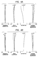
- FIG. 4A is an aberration diagram at the wide angle end and in focus at 3.0 m according to Numerical Embodiment 1.
- FIG. 4B is an aberration diagram at a telephoto end and in focus at 3.0 m according to Numerical Embodiment 1.
- FIG. 5 is a cross sectional view at the wide angle end and in focus at infinity according to Numerical Embodiment 2.
- FIG. 6A is an aberration diagram at the wide angle end and in focus at 3.0 m according to Numerical Embodiment 2.
- FIG. 6B is an aberration diagram at the telephoto end and in focus at 3.0 m according to Numerical Embodiment 2.
- FIG. 7 is a cross sectional view at the wide angle end and in focus at infinity according to Numerical Embodiment 3.
- FIG. 8A is an aberration diagram at the wide angle end and in focus at 3.0 m according to Numerical Embodiment 3.
- FIG. 8B is an aberration diagram at the telephoto end and in focus at 3.0 m according to Numerical Embodiment 3.
- FIG. 9 is a cross sectional view at the wide angle end and in focus at infinity according to Numerical Embodiment 4.
- FIG. 10A is an aberration diagram at the wide angle end and in focus at 13 m according to Numerical Embodiment 4.
- FIG. 10B is an aberration diagram at the telephoto end and in focus at 13 m according to Numerical Embodiment 4.
- FIG. 11 is a cross sectional view at the wide angle end and in focus at infinity according to Numerical Embodiment 5.
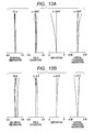
- FIG. 12A is an aberration diagram at the wide angle end and in focus at 13 m according to Numerical Embodiment 5.
- FIG. 12B is an aberration diagram at the telephoto end and in focus at 13 m according to Numerical Embodiment 5.
- the zoom lens system of the present invention includes at least, in order from an object side, a first lens unit having a positive refractive power that does not move for magnification-varying, a second lens unit having a negative refractive power that moves for magnification-varying, a third lens unit having a positive or negative refractive power for correcting image plane variation due to magnification-varying, and a fourth lens unit having a positive refractive power that does not move for magnification-varying but moves for image formation.
- the first lens unit includes, in order from the object side, a first sub lens unit that does not move for focusing, and a second sub lens unit having a positive refractive power that moves for focusing.
- an Abbe constant of a positive lens Lp having a smallest Abbe constant among lenses of the first lens unit is denoted by vp
- a partial dispersion ratio thereof is denoted by ⁇ p
- a refractive power thereof is denoted by ⁇ p
- an average value of Abbe constants of positive lenses except the positive lens Lp is denoted by ⁇ ap
- an average value of partial dispersion ratios of negative lenses of the first lens unit is denoted by ⁇ an
- a refractive power of the first lens unit is denoted by ⁇ 1
- a refractive power of the entire zoom lens system at the telephoto end is denoted by ⁇ tele.
- conditional expressions (6) and (7) may be satisfied.
- Ng a refractive index for g-line
- NF a refractive index for F-line
- Nd a refractive index for d-line
- NC a refractive index for C-line
- a structure of the zoom lens system, dispersion characteristic of lens material, and condition of refractive power are defined, to thereby define a condition for correcting secondary spectrum of longitudinal chromatic aberration at the telephoto end and for realizing good optical performance.
- conditional expressions (1) to (8) define the conditions for reducing a remaining secondary spectrum amount of longitudinal chromatic aberration in the first lens unit and for appropriately correcting the secondary spectrum of the longitudinal chromatic aberration at the telephoto end. An outline of the conditions is described with reference to FIGS. 1 and 2 .
- FIG. 1 illustrates a schematic diagram illustrating dichroic achromatism and remaining secondary spectrum of the positive lens unit.
- FIG. 2 illustrates a schematic diagram of distribution of an Abbe constant ⁇ and a partial dispersion ratio ⁇ of existing optical materials.
- the existing optical material is distributed in the region having narrow partial dispersion ratio ⁇ with respect to the Abbe constant v, and there is a tendency that the partial dispersion ratio ⁇ increases as the Abbe constant ⁇ decreases.
- a correction condition of chromatic aberration of a thin lens system which has a predetermined refractive power ⁇ and is constituted of two lenses 1 and 2 having refractive powers ⁇ 1 and ⁇ 2 and Abbe constants ⁇ 1 and v2, respectively, is expressed by the following equation.
- ⁇ is expressed as follows.
- the refractive powers ⁇ 1 and ⁇ 2 are expressed by the following equations by solving the equations (11) and (12).
- ⁇ ⁇ 1 ⁇ ⁇ ⁇ ⁇ 1 / ⁇ ⁇ 1 - ⁇ ⁇ 2
- ⁇ ⁇ 2 - ⁇ ⁇ ⁇ ⁇ 2 / ⁇ ⁇ 1 - ⁇ ⁇ 2
- the positive lens 1 has a small partial dispersion ratio ⁇ 1
- the negative lens 2 has a large partial dispersion ratio ⁇ 2 as illustrated in FIG. 2 .
- This deviation amount defined as a secondary spectrum amount ⁇ is expressed by the following equation.
- the secondary spectrum amounts of the first sub lens unit, the second sub lens unit, and the lens units after the magnification-varying system are denoted by ⁇ 1a, ⁇ 1b, and ⁇ Z, respectively.
- Image formation zooming factors of the second sub lens unit and the lens units after the magnification-varying system are denoted by ⁇ 1b and ⁇ Z, respectively.
- the secondary spectrum amount ⁇ of the entire lens system is expressed by the following equation.
- ⁇ ⁇ ⁇ 1 ⁇ a ⁇ ⁇ ⁇ 1 ⁇ b 2 ⁇ ⁇ Z 2 + ⁇ ⁇ 1 ⁇ b ⁇ 1 - ⁇ ⁇ 1 ⁇ b ⁇ ⁇ Z 2 + ⁇ Z ⁇ 1 - ⁇ Z
- the secondary spectrum amount ⁇ becomes significant in the first sub lens unit and the second sub lens unit in which an axial marginal light beam passes through at a high position on the telephoto side. Therefore, the secondary spectrum amount ⁇ of the longitudinal chromatic aberration may be reduced on the telephoto side by suppressing the sum of the secondary spectrum amounts ⁇ 1a and ⁇ 1b of the longitudinal chromatic aberration generated in the first sub lens unit and the second sub lens unit.
- conditional expression (1) defines a relationship of partial dispersion ratios ⁇ of positive and negative lenses for appropriately correcting the secondary spectrum of the longitudinal chromatic aberration at the telephoto end.
- the secondary spectrum of the longitudinal chromatic aberration at the telephoto end is corrected excessively, and it becomes difficult to maintain performance balance between the longitudinal chromatic aberration and lateral chromatic aberration in the entire zoom range.
- the lower limit condition of the conditional expression (1) is not satisfied, it becomes difficult to suppress the secondary spectrum of the longitudinal chromatic aberrations at the telephoto end.
- conditional expression (2) defines a relationship between the Abbe constant ⁇ of the positive lenses and the refractive power ⁇ tele at the telephoto end, in order to satisfy both achromatism for the C-line and the F-line and the correction of the secondary spectrum at the telephoto end.
- the secondary spectrum of the longitudinal chromatic aberration at the telephoto end is corrected excessively, and it becomes difficult to maintain performance balance between the longitudinal chromatic aberration and the lateral chromatic aberration in the entire zoom range.
- the refractive power ⁇ tele increases and the focal length decreases, it becomes difficult to achieve high magnification ratio.
- the lower limit condition of the conditional expression (2) is not satisfied, it becomes difficult to achieve both the achromatism for the C-line and the F-line and the correction of the secondary spectrum.
- the refractive power of each lens increases, and hence it is difficult to maintain good optical performance.
- the number of lenses increases, and hence it becomes difficult to achieve a small size and light weight.
- the expression (2) is more preferred to satisfy the following conditional expression.
- the conditional expression (3) defines a ratio between the refractive power ⁇ p of the positive lens Lp and the refractive power ⁇ 1 of the first lens unit, in order to achieve both the achromatism for the C-line and the F-line and the correction of the secondary spectrum at the telephoto end. If the upper limit condition of the conditional expression (3) is not satisfied, it becomes difficult to achieve the achromatism for the C-line and the F-line. In order to achieve the achromatism, the refractive power of each lens increases, and hence it becomes difficult to maintain good optical performance. In another case, the number of lenses increases, and hence it becomes difficult to achieve a small size and light weight. In addition, if the lower limit condition of the conditional expression (3) is not satisfied, the correction effect of the secondary spectrum is decreased.
- the conditional expression (4) defines a relationship between the refractive power ⁇ p, and the average value of Abbe constants of the positive lenses except the positive lens Lp and the average value of Abbe constants of the negative lenses, in order to achieve both the achromatism for the C-line and the F-line and the correction of the secondary spectrum at the telephoto end. If the upper limit condition of the conditional expression (4) is not satisfied, the secondary spectrum correction effect is decreased. If the lower limit condition of the conditional expression (4) is not satisfied, the achromatism for the C-line and the F-line becomes difficult to achieve. In order to achieve the achromatism for the C-line and the F-line, the refractive power of each lens increases, and hence it becomes difficult to maintain good optical performance. In another case, the number of lenses increases, and hence it becomes difficult to achieve a small size and light weight.
- the conditional expression (4) is more preferred to satisfy the following conditional expression.
- the conditional expression (5) defines a ratio between the sum ⁇ n of refractive powers of negative lenses of the first lens unit and the refractive power ⁇ 1, in order to realize the achromatism for the C-line and the F-line and good optical performance. If the upper limit condition of the conditional expression (5) is not satisfied, it becomes difficult to realize good optical performance. In another case, the number of lenses increases, and hence it becomes difficult to achieve a small size and light weight. In addition, if the lower limit condition of the conditional expression (5) is not satisfied, the achromatism for the C-line and the F-line becomes difficult to achieve.
- the conditional expression (6) and the conditional expression (7) define a relationship among the refractive power ⁇ p, the Abbe constant vp of the positive lens Lp, the sum ⁇ n of refractive powers of negative lenses of the first lens unit, and the average value ⁇ an of Abbe constants of the negative lenses of the first lens unit, in order to achieve both the achromatism for the C-line and the F-line and the correction of the secondary spectrum, and to realize good optical performance. If the upper limit condition of the conditional expression (6) is not satisfied, the achromatism for the C-line and the F-line becomes difficult to achieve. If the lower limit condition of the conditional expression (6) is not satisfied, the secondary spectrum correction effect is decreased. In another case, the refractive power of the negative lens is increased, and hence it becomes difficult to realize good optical performance. In still another case, the number of lenses increases, and hence it becomes difficult to achieve a small size and light weight.
- conditional expression (7) if the value of vp is larger than the value of ⁇ an so that the upper limit condition is not satisfied, the secondary spectrum correction effect is decreased. In addition, if the value of vp is smaller than the value of ⁇ an so that the upper limit condition is not satisfied, the achromatism for the C-line and the F-line becomes difficult to achieve.
- the conditional expression (7) is more preferred to satisfy the following condition.
- conditional expression (8) defines a ratio between the refractive power ⁇ 2 of the second lens unit and the refractive power ⁇ p, in order to achieve both the high magnification ratio and the correction of the secondary spectrum.
- the upper limit condition of the conditional expression (8) If the upper limit condition of the conditional expression (8) is not satisfied, it becomes difficult to achieve the high magnification ratio. In addition, the focal length at the telephoto end decreases, and hence the secondary spectrum at the telephoto end can be corrected by a known method. In addition, if the lower limit condition of the conditional expression (8) is not satisfied, the refractive power of the second lens unit increases, and hence it becomes difficult to maintain good optical performance over the entire zoom range. In another case, the number of lenses increases, and hence it becomes difficult to achieve a small size and light weight.
- conditional expressions (1) to (8) use the average value for defining. If a lens having an extremely small refractive power like a flat glass plate is included, the range of the conditional expression may be exceeded. Therefore, it is supposed that using any number of lenses having an extremely small refractive power is included in the present invention.
- FIG. 3 is a cross sectional view of lenses at a wide angle end and in focus at an object distance of infinity according to Numerical Embodiment 1 as a first embodiment of the present invention.
- FIGS. 4A and 4B illustrate aberration diagrams at the wide angle end and the telephoto end, respectively, in focus at an object distance of 3 m according to Numerical Embodiment 1.
- a solid line indicates an e-line
- a chain double-dashed line indicates a g-line
- a dashed dotted line indicates a C-line
- a dotted line indicates an F-line.
- aspheric coefficients are denoted by A3 to A12.
- the aspheric coefficients are expressed by the following expression.
- a paraxial curvature radius is denoted by R
- a conic constant is denoted by K.
- a front lens unit F has a positive refractive power as the first lens unit and does not move in the optical axis direction for magnification-varying.
- the first lens unit F includes a first sub lens unit that is disposed closest to the object side and does not move in the optical axis direction for focusing, and a second sub lens unit that is disposed on an image side and moves in the optical axis direction for focusing.
- a variator V as the second lens unit has a negative refractive power for magnification-varying and performs the magnification-varying from the wide angle end to the telephoto end by monotonously moving to the image plane side on the optical axis.
- a compensator C as the third lens unit has a negative refractive power and moves along the optical axis in a non-linear manner in order to correct image plane variation due to the magnification-varying.
- the variator V and the compensator C constitute the magnification-varying system.
- the zoom lens system further includes an aperture stop SP, and a relay lens unit R as the fourth lens unit, which has a positive refractive power for image formation action and does not move in the optical axis direction for the magnification-varying.
- the zoom lens system further includes a color separating prism or an optical filter P, which is illustrated as a glass block in FIG. 3 , and an imaging plane I.
- the first lens unit corresponds to first to twelfth surfaces, and includes the first sub lens unit having the first to the sixth surfaces and the second sub lens unit having the seventh to the twelfth surfaces.
- the first sub lens unit includes, in order from the object side, a negative lens, a positive lens, and a positive lens.
- the second sub lens unit includes three positive lenses.
- the positive lens having the smallest Abbe constant in the first lens unit is constituted of the fifth surface and the sixth surface.
- Table 1 shows correspondence values of the conditional expressions in this embodiment.
- This embodiment has a feature that the expressions (1), (4), (6), and (8) are close to the lower limit, the expression (3) is close to the upper limit, and an absolute value in the expression (7) is small.
- This numerical embodiment satisfies all the conditional expressions, and hence achieves high magnification zoom, a small size, and light weight while appropriately correcting the longitudinal chromatic aberration at the telephoto end.
- FIG. 5 is a cross sectional view of lenses at the wide angle end and in focus at an object distance of infinity according to Numerical Embodiment 2 as a second embodiment of the present invention.
- FIGS. 6A and 6B illustrate aberration diagrams at the wide angle end and the telephoto end, respectively, in focus at an object distance of 3 m according to Numerical Embodiment 2.
- a full line indicates an e-line
- a chain double-dashed line indicates a g-line
- a dashed dotted line indicates a C-line
- a dotted line indicates an F-line.
- a front lens unit F has a positive refractive power as the first lens unit and does not move in the optical axis direction for magnification-varying.
- the first sub lens unit 1a is a partial lens system disposed closest to the object side in the first lens unit F and does not move in the optical axis direction for focusing.
- the second sub lens unit 1b is a positive partial lens system disposed on the image side in the first lens unit F and moves for focusing.
- a variator V as the second lens unit has a negative refractive power for magnification-varying and performs the magnification-varying from the wide angle end to the telephoto end by monotonously moving to the image plane side on the optical axis.
- a compensator C as the third lens unit has a negative refractive power and moves along the optical axis in a non-linear manner in order to correct image plane variation due to the magnification-varying.
- the variator V and the compensator C constitute the magnification-varying system.
- the zoom lens system further includes an aperture stop SP, and a relay lens unit R as the fourth lens unit, which has a positive refractive power for image formation action and does not move in the optical axis direction for the magnification-varying.
- the zoom lens system further includes a color separating prism or an optical filter P, which is illustrated as a glass block in FIG. 5 , and an imaging plane I.
- the first lens unit corresponds to the first to the twelfth surfaces, and includes the first sub lens unit having the first to the sixth surfaces and the second sub lens unit having the seventh to the twelfth surfaces.
- the first sub lens unit includes, in order from the object side, a negative lens, a positive lens, and a positive lens.
- the second sub lens unit includes three positive lenses.
- the positive lens having the smallest Abbe constant in the first lens unit is constituted of the seventh surface and the eighth surface.
- Table 1 shows correspondence values of the conditional expressions in this embodiment.
- This embodiment has a feature that the expressions (1), (2), (4), (5), (6), and (8) are close to the upper limit, and that an absolute value in the expression (7) is relatively large.
- This numerical embodiment satisfies all the conditional expressions, and hence achieves high magnification zoom, a small size, and light weight while appropriately correcting the longitudinal chromatic aberration at the telephoto end.
- FIG. 7 is a cross sectional view of lenses at a wide angle end and in focus at an object distance of infinity according to Numerical Embodiment 3 as a third embodiment of the present invention.
- FIGS. 8A and 8B illustrate aberration diagrams at the wide angle end and the telephoto end, respectively, in focus at an object distance of 3 m according to Numerical Embodiment 3.
- a full line indicates an e-line
- a chain double-dashed line indicates a g-line
- a dashed dotted line indicates a C-line
- a dotted line indicates an F-line.
- a front lens unit F has a positive refractive power as the first lens unit and does not move in the optical axis direction for magnification-varying.
- the first sub lens unit 1a is a partial lens system 1a disposed closest to the object side in the first lens unit F and does not move in the optical axis direction for focusing.
- the second sub lens unit 1b is a positive partial lens system disposed on the image side in the first lens unit F and moves in the optical axis direction for focusing.
- a variator V as the second lens unit has a negative refractive power for magnification-varying and performs the magnification-varying from the wide angle end to the telephoto end by monotonously moving to the image plane side on the optical axis.
- a compensator C as the third lens unit has a negative refractive power and moves along the optical axis in a non-linear manner in order to correct image plane variation due to the magnification-varying.
- the variator V and the compensator C constitute the magnification-varying system.
- the zoom lens system further includes an aperture stop SP, and a relay lens unit R as the fourth lens unit, which has a positive refractive power for image formation action and does not move in the optical axis direction for the magnification-varying.
- the zoom lens system further includes a color separating prism or an optical filter P, which is illustrated as a glass block in FIG. 7 , and an imaging plane I.
- the first lens unit corresponds to the first to the thirteenth surfaces, and includes the first sub lens unit having the first to the seventh surfaces and the second sub lens unit having the eighth to the thirteenth surfaces.
- the first sub lens unit includes, in order from the object side, a negative lens, a negative lens, a positive lens, and a positive lens.
- the second sub lens unit includes three positive lenses.
- the positive lens having the smallest Abbe constant in the first lens unit is constituted of the sixth surface and the seventh surface.
- Table 1 shows correspondence values of the conditional expressions in this embodiment.
- This embodiment has a feature that the expression (5) is close to the lower limit, the expression (2) is close to the upper limit, and an absolute value in the expression (7) is relatively large.
- This numerical embodiment satisfies all the conditional expressions, and hence achieves high magnification zoom, a small size, and light weight while appropriately correcting the longitudinal chromatic aberration at the telephoto end.
- FIG. 9 is a cross sectional view of lenses at a wide angle end and in focus at an object distance of infinity according to Numerical Embodiment 4 as a fourth embodiment of the present invention.
- FIGS. 10A and 10B illustrate aberration diagrams at the wide angle end and the telephoto end, respectively, in focus at an object distance of 13 m according to Numerical Embodiment 4.
- a full line indicates an e-line
- a chain double-dashed line indicates a g-line
- a dashed dotted line indicates a C-line
- a dotted line indicates an F-line.
- a front lens unit F has a positive refractive power as the first lens unit and does not move in the optical axis direction for magnification-varying.
- the first sub lens unit 1a is a partial lens system disposed closest to the object side in the first lens unit F and does not move in the optical axis direction for focusing.
- the second sub lens unit 1b is a positive partial lens system disposed on the image side in the first lens unit F and moves in the optical axis direction for focusing.
- a variator V as the second lens unit has a negative refractive power for magnification-varying and performs the magnification-varying from the wide angle end to the telephoto end by monotonously moving to the image plane side on the optical axis.
- a compensator C as the third lens unit has a positive refractive power and moves along the optical axis in a non-linear manner in order to correct image plane variation due to the magnification-varying.
- the variator V and the compensator C constitute the magnification-varying system.
- the zoom lens system further includes an aperture stop SP, and a relay lens unit R as the fourth lens unit, which has a positive refractive power for image formation action and does not move in the optical axis direction for the magnification-varying.
- the zoom lens system further includes a color separating prism or an optical filter P, which is illustrated as a glass block in FIG. 9 , and an imaging plane I.
- the first lens unit corresponds to the first to the twelfth surfaces, and includes the first sub lens unit having the first to the sixth surfaces and the second sub lens unit having the seventh to the twelfth surfaces.
- the first sub lens unit includes, in order from the object side, a negative lens, a positive lens, and a positive lens.
- the second sub lens unit includes three positive lenses.
- the positive lens having the smallest Abbe constant in the first lens unit is constituted of the fifth surface and the sixth surface.
- Table 1 shows correspondence values of the conditional expressions in this embodiment.
- This embodiment is has a feature that an absolute value in the expression (7) is relatively large.
- This numerical embodiment satisfies all the conditional expressions, and hence achieves high magnification zoom, a small size, and light weight while appropriately correcting the longitudinal chromatic aberration at the telephoto end.
- FIG. 11 is a cross sectional view of lenses at the wide angle end and in focus at an object distance of infinity according to Numerical Embodiment 5 as a fifth embodiment of the present invention.
- FIGS. 12A and 12B illustrate aberration diagrams at the wide angle end and the telephoto end, respectively, in focus at an object distance of 13 m according to Numerical Embodiment 5.
- a full line indicates an e-line
- a chain double-dashed line indicates a g-line
- a dashed dotted line indicates a C-line
- a dotted line indicates an F-line.
- a front lens unit F has a positive refractive power as the first lens unit and does not move in the optical axis direction for magnification-varying.
- the first sub lens unit 1a is a partial lens system disposed closest to the object side in the first lens unit F and does not move in the optical axis direction for focusing.
- the second sub lens unit 1b is a positive partial lens system disposed on the image side in the first lens unit F and moves in the optical axis direction for focusing.
- a variator V as the second lens unit has a negative refractive power for magnification-varying and performs the magnification-varying from the wide angle end to the telephoto end by monotonously moving to the image plane side on the optical axis.
- a compensator C as the third lens unit has a positive refractive power and moves along the optical axis in a non-linear manner in order to correct image plane variation due to the magnification-varying.
- the variator V and the compensator C constitute the magnification-varying system.
- the zoom lens system further includes an aperture stop SP, and a relay lens unit R as the fourth lens unit, which has a positive refractive power for image formation action and does not move in the optical axis direction for the magnification-varying.
- the zoom lens system further includes a color separating prism or an optical filter P, which is illustrated as a glass block in FIG. 11 , and an imaging plane I.
- the first lens unit corresponds to the first to the twelfth surfaces, and includes the first sub lens unit having the first to the sixth surfaces and the second lens unit having the seventh to the twelfth surfaces.
- the first sub lens unit includes, in order from the object side, a negative lens, a positive lens, and a positive lens.
- the second sub lens unit includes three positive lenses.
- the positive lens having the smallest Abbe constant in the first lens unit is constituted of the seventh surface and the eighth surface.
- Table 1 shows correspondence values of the conditional expressions in this embodiment.
- This embodiment has a feature that the expression (2) is close to the lower limit.
- This numerical embodiment satisfies all the conditional expressions, and hence achieves high magnification zoom, a small size, and light weight while appropriately correcting the longitudinal chromatic aberration at the telephoto end.
- An image pickup apparatus is constituted of the zoom lens system according to any one of the above-mentioned embodiments, and a camera that is coupled to the zoom lens system for photographing a subject whose image is formed by the zoom lens system.
- the image pickup apparatus can appropriately correct the secondary spectrum of the longitudinal chromatic aberration on the telephoto side and can realize a small size and light weight.
Landscapes
- Physics & Mathematics (AREA)
- General Physics & Mathematics (AREA)
- Optics & Photonics (AREA)
- Chemical & Material Sciences (AREA)
- Dispersion Chemistry (AREA)
- Lenses (AREA)
Abstract



Description
- The present invention relates to a zoom lens system which is suitable for use in a broadcasting television camera, a video camera, a digital still camera, and a silver-halide camera, and also to an image pickup apparatus including the zoom lens system.
- Conventionally, as a zoom lens system used for an image pickup apparatus such as a television camera, a silver halide film camera, a digital camera, and a video camera, there is proposed a zoom lens system including, in order from the object side, a first lens unit having positive refractive power and including a focus unit, a second lens unit having negative refractive power for magnification-varying, a third lens unit having positive or negative refractive power for correcting image plane variation due to the magnification-varying, and a fourth lens unit having positive refractive power for image formation.
- Japanese Patent Application Laid-Open No.
2004-264458 H09-005628 - Japanese Patent Application Laid-Open No.
2004-264458 - Japanese Patent Application Laid-Open No.
H09-005628 - However, there is a problem that if it is intended to correct longitudinal chromatic aberration due to an increase in a focal length at a telephoto end because of a higher magnification ratio or to correct further longitudinal chromatic aberration on the telephoto side in the already disclosed zoom lens system, it is difficult to correct the longitudinal chromatic aberration sufficiently by the conventional technology.
- In view of the above, an object of the present invention is to provide a zoom lens system that is optimal for a high magnification zoom lens system for broadcasting in particular, and can appropriately correct secondary spectrum of longitudinal chromatic aberration on a telephoto side while achieving a small size and light weight, and to provide an image pickup apparatus including the zoom lens system.
- In order to attain the above-mentioned object, according to the present invention, there is provided a zoom lens system, including, in order from an object side; a first lens unit having a positive refractive power, a second lens unit having a negative refractive power that moves for magnification-varying, a third lens unit having one of a positive refractive power and a negative refractive power that moves for magnification-varying, and a fourth lens unit having a positive refractive power, in which when an Abbe constant of a positive lens Lp having a smallest Abbe constant among lenses constituting the first lens unit is denoted by vp, a partial dispersion ratio thereof is denoted by θp, a refractive power thereof is denoted by ϕp, an average value of Abbe constants of positive lenses except the positive lens Lp is denoted by vap, an average value of partial dispersion ratios of negative lenses of the first lens unit is denoted by θan, a refractive power of the first lens unit is denoted by ϕ1, and a refractive power of an entire zoom lens system at a telephoto end is denoted by ϕtele, the following conditional expressions are satisfied:


and
- Further, preferably, when an average value of Abbe constants of the negative lenses among the lenses constituting the first lens unit is denoted by van, and a sum of refractive powers of the negative lenses is denoted by ϕn, the following conditional expressions may be satisfied.
-

-

- More preferably, the following conditional expressions may be satisfied.
-

-

- Further, when a refractive power of the second lens unit is denoted by ϕ2, the following conditional expression is satisfied.
-

- Here, when a refractive index for g-line is denoted by Ng, a refractive index for F-line is denoted by NF, a refractive index for d-line is denoted by Nd, and a refractive index for C-line is denoted by NC, an Abbe constant ν and a partial dispersion ratio θ satisfy the following expressions, respectively.
-

-

- Further objects or other features of the present invention become apparent from the following description of exemplary embodiments and the like described with reference to the attached drawings.
- According to the present invention, it is possible to provide the zoom lens system having a high magnification of zoom ratio that can appropriately correct secondary spectrum of longitudinal chromatic aberration at the telephoto end while achieving a small size and light weight.
- Further features of the present invention will become apparent from the following description of exemplary embodiments with reference to the attached drawings.
-
FIG. 1 is a schematic diagram illustrating dichroic achromatism and remaining secondary spectrum of a positive lens unit. -
FIG. 2 is a schematic diagram of distribution of an Abbe constant ν and a partial dispersion ratio θ of optical materials. -
FIG. 3 is a cross sectional view at a wide angle end and in focus at infinity according to Numerical Embodiment 1. -
FIG. 4A is an aberration diagram at the wide angle end and in focus at 3.0 m according to Numerical Embodiment 1. -
FIG. 4B is an aberration diagram at a telephoto end and in focus at 3.0 m according to Numerical Embodiment 1. -
FIG. 5 is a cross sectional view at the wide angle end and in focus at infinity according to Numerical Embodiment 2. -
FIG. 6A is an aberration diagram at the wide angle end and in focus at 3.0 m according to Numerical Embodiment 2. -
FIG. 6B is an aberration diagram at the telephoto end and in focus at 3.0 m according to Numerical Embodiment 2. -
FIG. 7 is a cross sectional view at the wide angle end and in focus at infinity according to Numerical Embodiment 3. -
FIG. 8A is an aberration diagram at the wide angle end and in focus at 3.0 m according to Numerical Embodiment 3. -
FIG. 8B is an aberration diagram at the telephoto end and in focus at 3.0 m according to Numerical Embodiment 3. -
FIG. 9 is a cross sectional view at the wide angle end and in focus at infinity according to Numerical Embodiment 4. -
FIG. 10A is an aberration diagram at the wide angle end and in focus at 13 m according to Numerical Embodiment 4. -
FIG. 10B is an aberration diagram at the telephoto end and in focus at 13 m according to Numerical Embodiment 4. -
FIG. 11 is a cross sectional view at the wide angle end and in focus at infinity according toNumerical Embodiment 5. -
FIG. 12A is an aberration diagram at the wide angle end and in focus at 13 m according toNumerical Embodiment 5. -
FIG. 12B is an aberration diagram at the telephoto end and in focus at 13 m according toNumerical Embodiment 5. - An outline of a zoom lens system according to the present invention is described below.
- The zoom lens system of the present invention includes at least, in order from an object side, a first lens unit having a positive refractive power that does not move for magnification-varying, a second lens unit having a negative refractive power that moves for magnification-varying, a third lens unit having a positive or negative refractive power for correcting image plane variation due to magnification-varying, and a fourth lens unit having a positive refractive power that does not move for magnification-varying but moves for image formation.
- The first lens unit includes, in order from the object side, a first sub lens unit that does not move for focusing, and a second sub lens unit having a positive refractive power that moves for focusing.
- Conditional expressions in the present invention are described.
- It is defined that an Abbe constant of a positive lens Lp having a smallest Abbe constant among lenses of the first lens unit is denoted by vp, a partial dispersion ratio thereof is denoted by θp, a refractive power thereof is denoted by ϕp, an average value of Abbe constants of positive lenses except the positive lens Lp is denoted by νap, an average value of partial dispersion ratios of negative lenses of the first lens unit is denoted by θan, a refractive power of the first lens unit is denoted by ϕ1, and a refractive power of the entire zoom lens system at the telephoto end is denoted by ϕtele. Then, it suffices that the following conditional expressions (1) to (3) be satisfied.
-

-

-

- Preferably, when an average value of Abbe constants of negative lenses among the lenses constituting the first lens unit is denoted by νan, and a sum of refractive powers of the negative lenses is denoted by ϕn, the following conditional expressions (4) and (5) may be satisfied.
-

-

- More preferably, the following conditional expressions (6) and (7) may be satisfied.
-

-

- In addition, when a refractive power of the second lens unit is denoted by ϕ2, it suffices that the following conditional expression (8) be satisfied.
-

- Here, when a refractive index for g-line is denoted by Ng, a refractive index for F-line is denoted by NF, a refractive index for d-line is denoted by Nd, and a refractive index for C-line is denoted by NC, an Abbe constant ν and a partial dispersion ratio θ satisfy the following expressions (9) and (10), respectively.
-

-

- In each conditional expression, a structure of the zoom lens system, dispersion characteristic of lens material, and condition of refractive power are defined, to thereby define a condition for correcting secondary spectrum of longitudinal chromatic aberration at the telephoto end and for realizing good optical performance.
- The conditional expressions (1) to (8) define the conditions for reducing a remaining secondary spectrum amount of longitudinal chromatic aberration in the first lens unit and for appropriately correcting the secondary spectrum of the longitudinal chromatic aberration at the telephoto end. An outline of the conditions is described with reference to
FIGS. 1 and 2 . -
FIG. 1 illustrates a schematic diagram illustrating dichroic achromatism and remaining secondary spectrum of the positive lens unit. -
FIG. 2 illustrates a schematic diagram of distribution of an Abbe constant ν and a partial dispersion ratio θ of existing optical materials. - As illustrated in
FIG. 2 , the existing optical material is distributed in the region having narrow partial dispersion ratio θ with respect to the Abbe constant v, and there is a tendency that the partial dispersion ratio θ increases as the Abbe constant ν decreases. - A correction condition of chromatic aberration of a thin lens system which has a predetermined refractive power ϕ and is constituted of two lenses 1 and 2 having refractive powers ϕ1 and ϕ2 and Abbe constants ν1 and v2, respectively, is expressed by the following equation.
-

- Here, ϕ is expressed as follows.
-

- If the equation (11) is satisfied, an image formation position is identical between the C-line and the F-line.
- In this case, the refractive powers ϕ1 and ϕ2 are expressed by the following equations by solving the equations (11) and (12).
-

-

- In
FIG. 1 , as to the achromatism for the positive lens unit, a material having a large Abbe constant ν1 is used for the positive lens 1, and a material having a small Abbe constant ν2 is used for the negative lens 2. Therefore, the positive lens 1 has a small partial dispersion ratio θ1, and the negative lens 2 has a large partial dispersion ratio θ2 as illustrated inFIG. 2 . Thus, if the chromatic aberration is corrected at the F-line and the C-line, the image formation point at the g-line is shifted to the image side. This deviation amount defined as a secondary spectrum amount Δ is expressed by the following equation. -

- Here, it is defined that the secondary spectrum amounts of the first sub lens unit, the second sub lens unit, and the lens units after the magnification-varying system are denoted by Δ1a, Δ1b, and ΔZ, respectively. Image formation zooming factors of the second sub lens unit and the lens units after the magnification-varying system are denoted by β1b and βZ, respectively. Then, the secondary spectrum amount Δ of the entire lens system is expressed by the following equation.
-

- The secondary spectrum amount Δ becomes significant in the first sub lens unit and the second sub lens unit in which an axial marginal light beam passes through at a high position on the telephoto side. Therefore, the secondary spectrum amount Δ of the longitudinal chromatic aberration may be reduced on the telephoto side by suppressing the sum of the secondary spectrum amounts Δ1a and Δ1b of the longitudinal chromatic aberration generated in the first sub lens unit and the second sub lens unit.
- The conditional expression (1) defines a relationship of partial dispersion ratios θ of positive and negative lenses for appropriately correcting the secondary spectrum of the longitudinal chromatic aberration at the telephoto end.
- If the upper limit condition of the conditional expression (1) is not satisfied, the secondary spectrum of the longitudinal chromatic aberration at the telephoto end is corrected excessively, and it becomes difficult to maintain performance balance between the longitudinal chromatic aberration and lateral chromatic aberration in the entire zoom range. In addition, if the lower limit condition of the conditional expression (1) is not satisfied, it becomes difficult to suppress the secondary spectrum of the longitudinal chromatic aberrations at the telephoto end.
- The conditional expression (2) defines a relationship between the Abbe constant ν of the positive lenses and the refractive power ϕtele at the telephoto end, in order to satisfy both achromatism for the C-line and the F-line and the correction of the secondary spectrum at the telephoto end.
- If the upper limit condition of the conditional expression (2) is not satisfied, the secondary spectrum of the longitudinal chromatic aberration at the telephoto end is corrected excessively, and it becomes difficult to maintain performance balance between the longitudinal chromatic aberration and the lateral chromatic aberration in the entire zoom range. In addition, because the refractive power ϕtele increases and the focal length decreases, it becomes difficult to achieve high magnification ratio. If the lower limit condition of the conditional expression (2) is not satisfied, it becomes difficult to achieve both the achromatism for the C-line and the F-line and the correction of the secondary spectrum. In addition, in order to achieve the achromatism for the C-line and the F-line, the refractive power of each lens increases, and hence it is difficult to maintain good optical performance. In another case, the number of lenses increases, and hence it becomes difficult to achieve a small size and light weight. The expression (2) is more preferred to satisfy the following conditional expression.
-

- The conditional expression (3) defines a ratio between the refractive power ϕp of the positive lens Lp and the refractive power ϕ1 of the first lens unit, in order to achieve both the achromatism for the C-line and the F-line and the correction of the secondary spectrum at the telephoto end. If the upper limit condition of the conditional expression (3) is not satisfied, it becomes difficult to achieve the achromatism for the C-line and the F-line. In order to achieve the achromatism, the refractive power of each lens increases, and hence it becomes difficult to maintain good optical performance. In another case, the number of lenses increases, and hence it becomes difficult to achieve a small size and light weight. In addition, if the lower limit condition of the conditional expression (3) is not satisfied, the correction effect of the secondary spectrum is decreased.
- The conditional expression (4) defines a relationship between the refractive power ϕp, and the average value of Abbe constants of the positive lenses except the positive lens Lp and the average value of Abbe constants of the negative lenses, in order to achieve both the achromatism for the C-line and the F-line and the correction of the secondary spectrum at the telephoto end. If the upper limit condition of the conditional expression (4) is not satisfied, the secondary spectrum correction effect is decreased. If the lower limit condition of the conditional expression (4) is not satisfied, the achromatism for the C-line and the F-line becomes difficult to achieve. In order to achieve the achromatism for the C-line and the F-line, the refractive power of each lens increases, and hence it becomes difficult to maintain good optical performance. In another case, the number of lenses increases, and hence it becomes difficult to achieve a small size and light weight. The conditional expression (4) is more preferred to satisfy the following conditional expression.
-

- The conditional expression (5) defines a ratio between the sum ϕn of refractive powers of negative lenses of the first lens unit and the refractive power ϕ1, in order to realize the achromatism for the C-line and the F-line and good optical performance. If the upper limit condition of the conditional expression (5) is not satisfied, it becomes difficult to realize good optical performance. In another case, the number of lenses increases, and hence it becomes difficult to achieve a small size and light weight. In addition, if the lower limit condition of the conditional expression (5) is not satisfied, the achromatism for the C-line and the F-line becomes difficult to achieve.
- The conditional expression (6) and the conditional expression (7) define a relationship among the refractive power ϕp, the Abbe constant vp of the positive lens Lp, the sum ϕn of refractive powers of negative lenses of the first lens unit, and the average value νan of Abbe constants of the negative lenses of the first lens unit, in order to achieve both the achromatism for the C-line and the F-line and the correction of the secondary spectrum, and to realize good optical performance. If the upper limit condition of the conditional expression (6) is not satisfied, the achromatism for the C-line and the F-line becomes difficult to achieve. If the lower limit condition of the conditional expression (6) is not satisfied, the secondary spectrum correction effect is decreased. In another case, the refractive power of the negative lens is increased, and hence it becomes difficult to realize good optical performance. In still another case, the number of lenses increases, and hence it becomes difficult to achieve a small size and light weight.
- In the conditional expression (7), if the value of vp is larger than the value of νan so that the upper limit condition is not satisfied, the secondary spectrum correction effect is decreased. In addition, if the value of vp is smaller than the value of νan so that the upper limit condition is not satisfied, the achromatism for the C-line and the F-line becomes difficult to achieve. The conditional expression (7) is more preferred to satisfy the following condition.
-

- The conditional expression (8) defines a ratio between the refractive power ϕ2 of the second lens unit and the refractive power ϕp, in order to achieve both the high magnification ratio and the correction of the secondary spectrum.
- If the upper limit condition of the conditional expression (8) is not satisfied, it becomes difficult to achieve the high magnification ratio. In addition, the focal length at the telephoto end decreases, and hence the secondary spectrum at the telephoto end can be corrected by a known method. In addition, if the lower limit condition of the conditional expression (8) is not satisfied, the refractive power of the second lens unit increases, and hence it becomes difficult to maintain good optical performance over the entire zoom range. In another case, the number of lenses increases, and hence it becomes difficult to achieve a small size and light weight.
- In addition, some of the conditional expressions (1) to (8) use the average value for defining. If a lens having an extremely small refractive power like a flat glass plate is included, the range of the conditional expression may be exceeded. Therefore, it is supposed that using any number of lenses having an extremely small refractive power is included in the present invention.
-
FIG. 3 is a cross sectional view of lenses at a wide angle end and in focus at an object distance of infinity according to Numerical Embodiment 1 as a first embodiment of the present invention.FIGS. 4A and 4B illustrate aberration diagrams at the wide angle end and the telephoto end, respectively, in focus at an object distance of 3 m according to Numerical Embodiment 1. In the aberration diagrams, a solid line indicates an e-line, a chain double-dashed line indicates a g-line, a dashed dotted line indicates a C-line, and a dotted line indicates an F-line. In addition, aspheric coefficients are denoted by A3 to A12. When a displacement in the optical axis direction at a position of a height H from the optical axis with reference to a surface vertex is denoted by x, the aspheric coefficients are expressed by the following expression. -

- In this expression, a paraxial curvature radius is denoted by R, and a conic constant is denoted by K.
- In
FIG. 3 , a front lens unit F has a positive refractive power as the first lens unit and does not move in the optical axis direction for magnification-varying. The first lens unit F includes a first sub lens unit that is disposed closest to the object side and does not move in the optical axis direction for focusing, and a second sub lens unit that is disposed on an image side and moves in the optical axis direction for focusing. A variator V as the second lens unit has a negative refractive power for magnification-varying and performs the magnification-varying from the wide angle end to the telephoto end by monotonously moving to the image plane side on the optical axis. A compensator C as the third lens unit has a negative refractive power and moves along the optical axis in a non-linear manner in order to correct image plane variation due to the magnification-varying. The variator V and the compensator C constitute the magnification-varying system. The zoom lens system further includes an aperture stop SP, and a relay lens unit R as the fourth lens unit, which has a positive refractive power for image formation action and does not move in the optical axis direction for the magnification-varying. The zoom lens system further includes a color separating prism or an optical filter P, which is illustrated as a glass block inFIG. 3 , and an imaging plane I. - Next, the first lens unit according to this embodiment is described. The first lens unit corresponds to first to twelfth surfaces, and includes the first sub lens unit having the first to the sixth surfaces and the second sub lens unit having the seventh to the twelfth surfaces. The first sub lens unit includes, in order from the object side, a negative lens, a positive lens, and a positive lens. The second sub lens unit includes three positive lenses.
- The positive lens having the smallest Abbe constant in the first lens unit is constituted of the fifth surface and the sixth surface.
- Table 1 shows correspondence values of the conditional expressions in this embodiment.
- This embodiment has a feature that the expressions (1), (4), (6), and (8) are close to the lower limit, the expression (3) is close to the upper limit, and an absolute value in the expression (7) is small.
- This numerical embodiment satisfies all the conditional expressions, and hence achieves high magnification zoom, a small size, and light weight while appropriately correcting the longitudinal chromatic aberration at the telephoto end.
- Note that in the following tables for the numerical embodiments, "e+xxx" and "e-xxx" represent "×10xxx" and "×10-xxx", respectively.
-
- Unit mm
- Surface data
- [Second embodiment]
-
FIG. 5 is a cross sectional view of lenses at the wide angle end and in focus at an object distance of infinity according to Numerical Embodiment 2 as a second embodiment of the present invention.FIGS. 6A and 6B illustrate aberration diagrams at the wide angle end and the telephoto end, respectively, in focus at an object distance of 3 m according to Numerical Embodiment 2. In the aberration diagrams, a full line indicates an e-line, a chain double-dashed line indicates a g-line, a dashed dotted line indicates a C-line, and a dotted line indicates an F-line. - In
FIG. 5 , a front lens unit F has a positive refractive power as the first lens unit and does not move in the optical axis direction for magnification-varying. The firstsub lens unit 1a is a partial lens system disposed closest to the object side in the first lens unit F and does not move in the optical axis direction for focusing. The secondsub lens unit 1b is a positive partial lens system disposed on the image side in the first lens unit F and moves for focusing. A variator V as the second lens unit has a negative refractive power for magnification-varying and performs the magnification-varying from the wide angle end to the telephoto end by monotonously moving to the image plane side on the optical axis. A compensator C as the third lens unit has a negative refractive power and moves along the optical axis in a non-linear manner in order to correct image plane variation due to the magnification-varying. The variator V and the compensator C constitute the magnification-varying system. The zoom lens system further includes an aperture stop SP, and a relay lens unit R as the fourth lens unit, which has a positive refractive power for image formation action and does not move in the optical axis direction for the magnification-varying. The zoom lens system further includes a color separating prism or an optical filter P, which is illustrated as a glass block inFIG. 5 , and an imaging plane I. - Next, the first lens unit according to this embodiment is described. The first lens unit corresponds to the first to the twelfth surfaces, and includes the first sub lens unit having the first to the sixth surfaces and the second sub lens unit having the seventh to the twelfth surfaces. The first sub lens unit includes, in order from the object side, a negative lens, a positive lens, and a positive lens. The second sub lens unit includes three positive lenses.
- The positive lens having the smallest Abbe constant in the first lens unit is constituted of the seventh surface and the eighth surface.
- Table 1 shows correspondence values of the conditional expressions in this embodiment.
- This embodiment has a feature that the expressions (1), (2), (4), (5), (6), and (8) are close to the upper limit, and that an absolute value in the expression (7) is relatively large.
- This numerical embodiment satisfies all the conditional expressions, and hence achieves high magnification zoom, a small size, and light weight while appropriately correcting the longitudinal chromatic aberration at the telephoto end.
-
- Unit mm
- Surface data
- [Third embodiment]
-
FIG. 7 is a cross sectional view of lenses at a wide angle end and in focus at an object distance of infinity according to Numerical Embodiment 3 as a third embodiment of the present invention.FIGS. 8A and 8B illustrate aberration diagrams at the wide angle end and the telephoto end, respectively, in focus at an object distance of 3 m according to Numerical Embodiment 3. In the aberration diagrams, a full line indicates an e-line, a chain double-dashed line indicates a g-line, a dashed dotted line indicates a C-line, and a dotted line indicates an F-line. - In
FIG. 7 , a front lens unit F has a positive refractive power as the first lens unit and does not move in the optical axis direction for magnification-varying. The firstsub lens unit 1a is apartial lens system 1a disposed closest to the object side in the first lens unit F and does not move in the optical axis direction for focusing. The secondsub lens unit 1b is a positive partial lens system disposed on the image side in the first lens unit F and moves in the optical axis direction for focusing. A variator V as the second lens unit has a negative refractive power for magnification-varying and performs the magnification-varying from the wide angle end to the telephoto end by monotonously moving to the image plane side on the optical axis. A compensator C as the third lens unit has a negative refractive power and moves along the optical axis in a non-linear manner in order to correct image plane variation due to the magnification-varying. The variator V and the compensator C constitute the magnification-varying system. The zoom lens system further includes an aperture stop SP, and a relay lens unit R as the fourth lens unit, which has a positive refractive power for image formation action and does not move in the optical axis direction for the magnification-varying. The zoom lens system further includes a color separating prism or an optical filter P, which is illustrated as a glass block inFIG. 7 , and an imaging plane I. - Next, the first lens unit according to this embodiment is described. The first lens unit corresponds to the first to the thirteenth surfaces, and includes the first sub lens unit having the first to the seventh surfaces and the second sub lens unit having the eighth to the thirteenth surfaces. The first sub lens unit includes, in order from the object side, a negative lens, a negative lens, a positive lens, and a positive lens. The second sub lens unit includes three positive lenses.
- The positive lens having the smallest Abbe constant in the first lens unit is constituted of the sixth surface and the seventh surface.
- Table 1 shows correspondence values of the conditional expressions in this embodiment.
- This embodiment has a feature that the expression (5) is close to the lower limit, the expression (2) is close to the upper limit, and an absolute value in the expression (7) is relatively large.
- This numerical embodiment satisfies all the conditional expressions, and hence achieves high magnification zoom, a small size, and light weight while appropriately correcting the longitudinal chromatic aberration at the telephoto end.
-
- Unit mm
- Surface data
- [Fourth embodiment]
-
FIG. 9 is a cross sectional view of lenses at a wide angle end and in focus at an object distance of infinity according to Numerical Embodiment 4 as a fourth embodiment of the present invention.FIGS. 10A and 10B illustrate aberration diagrams at the wide angle end and the telephoto end, respectively, in focus at an object distance of 13 m according to Numerical Embodiment 4. In the aberration diagrams, a full line indicates an e-line, a chain double-dashed line indicates a g-line, a dashed dotted line indicates a C-line, and a dotted line indicates an F-line. - In
FIG. 9 , a front lens unit F has a positive refractive power as the first lens unit and does not move in the optical axis direction for magnification-varying. The firstsub lens unit 1a is a partial lens system disposed closest to the object side in the first lens unit F and does not move in the optical axis direction for focusing. The secondsub lens unit 1b is a positive partial lens system disposed on the image side in the first lens unit F and moves in the optical axis direction for focusing. A variator V as the second lens unit has a negative refractive power for magnification-varying and performs the magnification-varying from the wide angle end to the telephoto end by monotonously moving to the image plane side on the optical axis. A compensator C as the third lens unit has a positive refractive power and moves along the optical axis in a non-linear manner in order to correct image plane variation due to the magnification-varying. The variator V and the compensator C constitute the magnification-varying system. The zoom lens system further includes an aperture stop SP, and a relay lens unit R as the fourth lens unit, which has a positive refractive power for image formation action and does not move in the optical axis direction for the magnification-varying. The zoom lens system further includes a color separating prism or an optical filter P, which is illustrated as a glass block inFIG. 9 , and an imaging plane I. - Next, the first lens unit according to this embodiment is described. The first lens unit corresponds to the first to the twelfth surfaces, and includes the first sub lens unit having the first to the sixth surfaces and the second sub lens unit having the seventh to the twelfth surfaces. The first sub lens unit includes, in order from the object side, a negative lens, a positive lens, and a positive lens. The second sub lens unit includes three positive lenses.
- The positive lens having the smallest Abbe constant in the first lens unit is constituted of the fifth surface and the sixth surface.
- Table 1 shows correspondence values of the conditional expressions in this embodiment.
- This embodiment is has a feature that an absolute value in the expression (7) is relatively large.
- This numerical embodiment satisfies all the conditional expressions, and hence achieves high magnification zoom, a small size, and light weight while appropriately correcting the longitudinal chromatic aberration at the telephoto end.
-
- Unit mm
- Surface data
- [Fifth embodiment]
-
FIG. 11 is a cross sectional view of lenses at the wide angle end and in focus at an object distance of infinity according toNumerical Embodiment 5 as a fifth embodiment of the present invention.FIGS. 12A and 12B illustrate aberration diagrams at the wide angle end and the telephoto end, respectively, in focus at an object distance of 13 m according toNumerical Embodiment 5. In the aberration diagrams, a full line indicates an e-line, a chain double-dashed line indicates a g-line, a dashed dotted line indicates a C-line, and a dotted line indicates an F-line. - In
FIG. 11 , a front lens unit F has a positive refractive power as the first lens unit and does not move in the optical axis direction for magnification-varying. The firstsub lens unit 1a is a partial lens system disposed closest to the object side in the first lens unit F and does not move in the optical axis direction for focusing. The secondsub lens unit 1b is a positive partial lens system disposed on the image side in the first lens unit F and moves in the optical axis direction for focusing. A variator V as the second lens unit has a negative refractive power for magnification-varying and performs the magnification-varying from the wide angle end to the telephoto end by monotonously moving to the image plane side on the optical axis. A compensator C as the third lens unit has a positive refractive power and moves along the optical axis in a non-linear manner in order to correct image plane variation due to the magnification-varying. The variator V and the compensator C constitute the magnification-varying system. The zoom lens system further includes an aperture stop SP, and a relay lens unit R as the fourth lens unit, which has a positive refractive power for image formation action and does not move in the optical axis direction for the magnification-varying. The zoom lens system further includes a color separating prism or an optical filter P, which is illustrated as a glass block inFIG. 11 , and an imaging plane I. - Next, the first lens unit according to this embodiment is described. The first lens unit corresponds to the first to the twelfth surfaces, and includes the first sub lens unit having the first to the sixth surfaces and the second lens unit having the seventh to the twelfth surfaces. The first sub lens unit includes, in order from the object side, a negative lens, a positive lens, and a positive lens. The second sub lens unit includes three positive lenses.
- The positive lens having the smallest Abbe constant in the first lens unit is constituted of the seventh surface and the eighth surface.
- Table 1 shows correspondence values of the conditional expressions in this embodiment.
- This embodiment has a feature that the expression (2) is close to the lower limit.
- This numerical embodiment satisfies all the conditional expressions, and hence achieves high magnification zoom, a small size, and light weight while appropriately correcting the longitudinal chromatic aberration at the telephoto end.
-
- Unit mm
- Surface data
- An image pickup apparatus is constituted of the zoom lens system according to any one of the above-mentioned embodiments, and a camera that is coupled to the zoom lens system for photographing a subject whose image is formed by the zoom lens system. Thus, it is possible to realize the image pickup apparatus that can appropriately correct the secondary spectrum of the longitudinal chromatic aberration on the telephoto side and can realize a small size and light weight.
- The exemplary embodiments of the present invention are described above, but needless to say, the present invention is not limited to those embodiments, and various modifications and changes can be made thereto without departing from the spirit of the present invention.
- [Table 6]
- Table 1 correspondence values of conditional expressions in Numerical Embodiments 1 to 5
Number of conditional expression Numerical Embodiment 1 Numerical Embodiment 2 Numerical Embodiment 3 Numerical Embodiment 4 Numerical Embodiment 5 (1) 0.000 0.123 0.092 0.092 0.067 (2) 0.013 0.020 0.020 0.012 0.011 (3) 0.370 0.073 0.211 0.199 0.067 (4) 0.085 0.423 0.143 0.158 0.132 (5) -0.775 -0.534 -0.829 -0.611 -0.613 (6) -0.478 -0.136 -0.254 -0.325 -0.389 (7) 0.000 6.380 6.380 6.380 4.630 (8) -0.084 -0.017 -0.048 -0.021 -0.025 - While the present invention has been described with reference to exemplary embodiments, it is to be understood that the invention is not limited to the disclosed exemplary embodiments. The scope of the following claims is to be accorded the broadest interpretation so as to encompass all such modifications and equivalent structures and functions.
| Surface Number | r | D | nd | vd | θgF | Effective diameter |
| 1 | -194.100 | 2.20 | 1.84666 | 23.8 | 0.621 | 74.53 |
| 2 | 92.143 | 4.52 | 71.87 | |||
| 3 | 104.970 | 8.46 | 1.43875 | 95.0 | 0.534 | 73.35 |
| 4 | -1944.773 | 0.50 | 73.39 | |||
| 5 | 1583.212 | 7.77 | 1.84666 | 23.8 | 0.621 | 73.42 |
| 6 | -141.639 | 6.16 | 73.40 | |||
| 7 | 147.739 | 6.95 | 1.43387 | 95.1 | 0.537 | 69.85 |
| 8 | -419.036 | 0.15 | 69.37 | |||
| 9 | 87.704 | 9.18 | 1.43387 | 95.1 | 0.537 | 64.64 |
| 10 | -323.707 | 0.15 | 63.68 | |||
| 11 | 44.477 | 7.43 | 1.43875 | 95.0 | 0.534 | 54.27 |
| 12 | 119.258 | (Variable) | 53.26 | |||
| 13 | 380.874 | 1.00 | 2.00330 | 28.3 | 0.598 | 18.01 |
| 14 | 12.885 | 4.49 | 14.88 | |||
| 15 | -17.048 | 4.67 | 1.92286 | 18.9 | 0.650 | 14.56 |
| 16 | -10.670 | 0.75 | 1.88300 | 40.8 | 0.567 | 15.07 |
| 17 | -1970.510 | 0.30 | 16.16 | |||
| 18 | 48.341 | 5.22 | 1.62588 | 35.7 | 0.589 | 17.06 |
| 19 | -19.189 | 0.93 | 17.80 | |||
| 20 | -14.733 | 0.75 | 1.88300 | 40.8 | 0.567 | 17.79 |
| 21 | -19.912 | (Variable) | 18.66 | |||
| 22 | -24.069 | 0.75 | 1.75500 | 52.3 | 0.548 | 19.00 |
| 23 | 49.851 | 2.91 | 1.84649 | 23.9 | 0.622 | 20.90 |
| 24 | -285.870 | (Variable) | 21.60 | |||
| 25 (Stop) | 0.000 | 1.63 | 24.87 | |||
| 26 | 171.561 | 4.79 | 1.67003 | 47.2 | 0.563 | 26.40 |
| 27 | -33.421 | 0.20 | 27.10 | |||
| 28 | 64.284 | 3.10 | 1.48749 | 70.2 | 0.530 | 27.90 |
| 29 | -300.791 | 0.15 | 27.80 | |||
| 30 | 70.545 | 6.14 | 1.50127 | 56.5 | 0.554 | 27.50 |
| 31 | -30.027 | 1.20 | 1.88300 | 40.8 | 0.567 | 27.10 |
| 32 | -1145.653 | 32.00 | 27.10 | |||
| 33 | 72.712 | 6.34 | 1.49700 | 81.5 | 0.538 | 25.34 |
| 34 | -37.239 | 0.47 | 24.92 | |||
| 35 | -72.757 | 1.40 | 1.83403 | 37.2 | 0.578 | 23.92 |
| 36 | 23.509 | 6.38 | 1.48749 | 70.2 | 0.530 | 23.05 |
| 37 | -416.047 | 2.67 | 23.30 | |||
| 38 | 59.003 | 6.54 | 1.50127 | 56.5 | 0.554 | 24.70 |
| 39 | -25.474 | 1.40 | 1.88300 | 40.8 | 0.567 | 24.85 |
| 40 | -62.880 | 1.40 | 25.78 | |||
| 41 | 45.276 | 4.82 | 1.50127 | 56.5 | 0.554 | 26.53 |
| 42 | -66.169 | 4.00 | 26.37 | |||
| 43 | 0.000 | 33.00 | 1.60859 | 46.4 | 0.566 | 40.00 |
| 44 | 0.000 | 13.20 | 1.51633 | 64.2 | 0.535 | 40.00 |
| 45 | 0.000 | 40.00 |
| Aspherical surface data | |||
| Thirteenth surface | |||
| K=-5.09201 e+003 | A 4=4.00985e-005 | A 6=-1.53470e-008 | A 8=-4.42023e-009 |
| A10=-7.20166e-012 | A12=5.37473e-014 | ||
| A 3=-1.61689e-006 A11=-1.17225e-012 | A 5=-1.92698e-006 | A 7=2.21125e-008 | A 9=4.06509e-010 |
| Various data | |||
| Zoom ratio | 16.50 |
| Wide angle | Intermediate | Telephoto | |
| Focal length | 8.00 | 32.48 | 132.00 |
| F-number | 1.88 | 1.88 | 2.50 |
| Angle of Field | 34.51 | 9.61 | 2.39 |
| Image height | 5.50 | 5.50 | 5.50 |
| Total lens length | 257.74 | 257.74 | 257.74 |
| BF | 7.53 | 7.53 | 7.53 |
| d12 | 0.38 | 29.97 | 42.18 |
| d21 | 38.50 | 4.88 | 0.77 |
| d24 | 5.26 | 9.28 | 1.19 |
| d45 | 7.53 | 7.53 | 7.53 |
| Entrance pupil position | 44.42 | 153.01 | 441.88 |
| Exit pupil position | 150.48 | 150.48 | 150.48 |
| Front principal point position | 52.86 | 192.87 | 695.77 |
| Rear principal point position | -0.47 | -24.95 | -124.47 |
| Zoom lens unit data | |||||
| Unit | First surface | Focal length | Lens structure length | Front principal point position | Rear principal point position |
| 1 | 1 | 56.43 | 53.48 | 31.41 | -0.57 |
| 2 | 13 | -12.86 | 18.11 | -1.00 | -16.56 |
| 3 | 22 | -37.90 | 3.66 | -0.26 | -2.27 |
| 4 | 25 | 79.32 | 130.83 | 104.19 | -181.87 |
| Surface Number | r | d | nd | vd | θgF | Effective diameter |
| 1 | -867.472 | 2.20 | 1.84666 | 23.8 | 0.603 | 74.10 |
| 2 | 100.879 | 7.11 | 70.89 | |||
| 3 | 629.150 | 5.70 | 1.43875 | 95.0 | 0.534 | 70.91 |
| 4 | -195.176 | 0.50 | 70.86 | |||
| 5 | 450.431 | 7.74 | 1.43387 | 95.1 | 0.537 | 69.81 |
| 6 | -158.575 | 6.42 | 69.33 | |||
| 7 | 282.092 | 3.76 | 1.94087 | 17.4 | 0.678 | 67.32 |
| 8 | 452.483 | 0.15 | 66.55 | |||
| 9 | 80.792 | 10.91 | 1.43387 | 95.1 | 0.537 | 64.50 |
| 10 | -186.781 | 0.15 | 63.75 | |||
| 11 | 46.937 | 7.46 | 1.59240 | 68.3 | 0.546 | 55.16 |
| 12 | 136.421 | (Variable) | 54.21 | |||
| 13 | 401.840 | 1.00 | 1.88300 | 40.8 | 0.567 | 18.80 |
| 14 | 12.026 | 4.81 | 15.13 | |||
| 15 | -18.763 | 4.97 | 1.88221 | 23.8 | 0.604 | 14.71 |
| 16 | -10.338 | 0.75 | 1.88300 | 40.8 | 0.567 | 15.00 |
| 17 | 99.549 | 0.30 | 16.31 | |||
| 18 | 41.317 | 5.28 | 1.72047 | 34.7 | 0.583 | 17.17 |
| 19 | -20.294 | 0.88 | 17.90 | |||
| 20 | -15.709 | 0.75 | 1.88300 | 40.8 | 0.567 | 17.88 |
| 21 | -22.799 | (Variable) | 18.71 | |||
| 22 | -24.069 | 0.75 | 1.75500 | 52.3 | 0.548 | 19.00 |
| 23 | 49.851 | 2.91 | 1.84649 | 23.9 | 0.622 | 20.90 |
| 24 | -285.870 | (Variable) | 21.60 | |||
| 25 (Stop) | 0.000 | 1.63 | 24.93 | |||
| 26 | 308.351 | 4.85 | 1.67003 | 47.2 | 0.563 | 26.40 |
| 27 | -30.391 | 0.20 | 27.10 | |||
| 28 | 54.847 | 3.30 | 1.48749 | 70.2 | 0.530 | 27.90 |
| 29 | -428.917 | 0.15 | 27.80 | |||
| 30 | 122.029 | 5.93 | 1.50127 | 56.5 | 0.554 | 27.50 |
| 31 | -27.054 | 1.20 | 1.88300 | 40.8 | 0.567 | 27.10 |
| 32 | -262.878 | 31.99 | 27.10 | |||
| 33 | 64.444 | 5.80 | 1.49700 | 81.5 | 0.538 | 26.50 |
| 34 | -41.047 | 0.47 | 26.18 | |||
| 35 | -236.331 | 1.40 | 1.83403 | 37.2 | 0.578 | 24.83 |
| 36 | 21.345 | 7.00 | 1.48749 | 70.2 | 0.530 | 23.45 |
| 37 | 118.392 | 2.67 | 23.35 | |||
| 38 | 50.359 | 6.56 | 1.50127 | 56.5 | 0.554 | 23.56 |
| 39 | -25.864 | 1.40 | 1.88300 | 40.8 | 0.567 | 23.27 |
| 40 | -72.216 | 1.40 | 23.95 | |||
| 41 | 45.399 | 4.30 | 1.50127 | 56.5 | 0.554 | 24.60 |
| 42 | -66.452 | 4.00 | 24.48 | |||
| 43 | 0.000 | 33.00 | 1.60859 | 46.4 | 0.566 | 40.00 |
| 44 | 0.000 | 13.20 | 1.51633 | 64.2 | 0.535 | 40.00 |
| 45 | 0.000 | 40.00 |
| Aspherical surface data | |||
| Thirteenth surface | |||
| K=-5.09201 e+003 | A 4=4.01004e-005 | A 6=-1.57839e-008 | A 8=-4.42907e-009 |
| A10=-7.28656e-012 | A12=5.14099e-014 | ||
| A 3=-1.57792e-006 | A 5=-1.92750e-006 | A 7=2.20666e-008 | A 9=4.05020e-010 |
| A11=-1.18440e-012 | |||
| Various data | |||
| Zoom ratio | 16.50 |
| Wide angle | Intermediate | Telephoto | |
| Focal length | 8.00 | 32.48 | 132.00 |
| F-number | 1.87 | 1.87 | 2.50 |
| Angle of Field | 34.51 | 9.61 | 2.39 |
| Image height | 5.50 | 5.50 | 5.50 |
| Total lens length | 256.94 | 256.94 | 256.94 |
| BF | 7.53 | 7.53 | 7.53 |
| d12 | 0.41 | 30.00 | 42.21 |
| d21 | 38.81 | 5.19 | 1.08 |
| d24 | 5.26 | 9.28 | 1.19 |
| d45 | 7.53 | 7.53 | 7.53 |
| Entrance pupil position | 45.67 | 154.26 | 443.13 |
| Exit pupil position | 175.27 | 175.27 | 175.27 |
| Front principal point position | 54.05 | 193.03 | 679.00 |
| Rear principal point position | -0.47 | -24.95 | -124.47 |
| Zoom lens unit data | |||||
| Unit | First surface | Focal length | Lens structure length | Front principal point position | Rear principal point position |
| 1 | 1 | 56.43 | 52.09 | 32.66 | -0.17 |
| 2 | 13 | -12.86 | 18.74 | -0.63 | -16.25 |
| 3 | 22 | -37.90 | 3.66 | -0.26 | -2.27 |
| 4 | 25 | 71.22 | 130.45 | 90.24 | -162.52 |
| Surface Number | r | d | nd | vd | θgF | Effective diameter |
| 1 | -311.357 | 2.20 | 1.84666 | 23.8 | 0.621 | 73.25 |
| 2 | 149.755 | 2.59 | 70.86 | |||
| 3 | 229.221 | 2.20 | 1.84666 | 218 | 0.621 | 70.76 |
| 4 | 85.557 | 12.56 | 1.43875 | 23.8 95.0 | 0.534 | 69.44 |
| 5 | -176.215 | 0.50 | 69.45 | |||
| 6 | 215.031 | 4.91 | 1.94087 | 17.4 | 0.678 | 68.72 |
| 7 | 1349.482 | 6.76 | 68.35 | |||
| 8 | 153.860 | 5.20 | 1.43387 | 95.1 | 0.537 | 67.45 |
| 9 | -3649.480 | 0.15 | 67.07 | |||
| 10 | 89.290 | 9.53 | 1.43387 | 95.1 | 0.537 | 64.32 |
| 11 | -244.511 | 0.15 | 63.53 | |||
| 12 | 56.462 | 6.18 | 1.75500 | 52.3 | 0.548 | 56.43 |
| 13 | 148.903 | (Variable) | 55.53 | |||
| 14 | 362.476 | 1.00 | 1.88300 | 40.8 | 0.567 | 20.67 |
| 15 | 12.455 | 5.86 | 16.54 | |||
| 16 | -23.132 | 4.67 | 1.92286 | 18.9 | 0.650 | 15.74 |
| 17 | -12.814 | 0.75 | 1.88300 | 40.8 | 0.567 | 15.97 |
| 18 | 123.434 | 0.30 | 16.46 | |||
| 19 | 39.242 | 4.73 | 1.65412 | 39.7 | 0.574 | 17.23 |
| 20 | -26.843 | 1.20 | 17.79 | |||
| 21 | -16.671 | 0.75 | 1.88300 | 40.8 | 0.567 | 17.79 |
| 22 | -22.506 | (Variable) | 18.51 | |||
| 23 | -24.069 | 0.75 | 1.75500 | 52.3 | 0.548 | 19.00 |
| 24 | 49.851 | 2.91 | 1.84649 | 23.9 | 0.622 | 20.90 |
| 25 | -285.870 | (Variable) | 21.60 | |||
| 26 (Stop) | 0.000 | 1.63 | 24.92 | |||
| 27 | 164.927 | 4.71 | 1.67003 | 47.2 | 0.563 | 26.40 |
| 28 | -34.600 | 0.20 | 27.10 | |||
| 29 | 59.197 | 3.63 | 1.48749 | 70.2 | 0.530 | 27.90 |
| 30 | -163.584 | 0.15 | 27.80 | |||
| 31 | 75.454 | 5.89 | 1.50127 | 56.5 | 03554 | 27.50 |
| 32 | -31.119 | 1.20 | 1.88300 | 40.8 | 0.567 | 27.10 |
| 33 | 1000.656 | 32.00 | 27.10 | |||
| 34 | 69.168 | 6.29 | 1.49700 | 81.5 | 0.538 | 27.10 |
| 35 | -37.293 | 0.47 | 24.78 | |||
| 36 | -66.586 | 1.40 | 1.83403 | 37.2 | 0.578 | 23.84 |
| 37 | 24.164 | 6.83 | 1.48749 | 70.2 | 0.530 | 23.04 |
| 38 | -433.599 | 2.67 | 23.89 | |||
| 39 | 56.136 | 6.23 | 1.50127 | 56.5 | 0.554 | 25.40 |
| 40 | -27.775 | 1.40 | 1.88300 | 40.8 | 0.567 | 25.52 |
| 41 | -63.618 | 1.40 | 26.34 | |||
| 42 | 39.020 | 4.31 | 1.50127 | 56.5 | 0.554 | 26.96 |
| 43 | -109.144 | 4.00 | 26.78 | |||
| 44 | 0.000 | 33.00 | 1.60859 | 46.4 | 0.566 | 40.00 |
| 45 | 0.000 | 13.20 | 1.51633 | 64.2 | 0.535 | 40.00 |
| 46 | 0.000 | 40.00 |
| Aspherical surface data | |||
| Fourteenth surface | |||
| K=-5.09201 e+003 | A 4=4.01061e-005 | A 6=-1.55724e-008 | A 8=-4.42447e-009 |
| A10=-7.21946e-012 | A12=5.26878e-014 | ||
| A 3=-1.42185e-006 | A 5=-1.92628e-006 | A 7=2.21013e-008 | A 9=4.05526e-010 |
| A11=-1.17668e-012 | |||
| Various data | |||
| Zoom ratio | 16.50 |
| Wide angle | Intermediate | Telephoto | |
| Focal length | 8.00 | 32.48 | 132.00 |
| F-number | 1.88 | 1.88 | 2.50 |
| Angle of Field | 34.51 | 9.61 | 2.39 |
| Image height | 5.50 | 5.50 | 5.50 |
| Total lens length | 259.62 | 259.62 | 259.62 |
| BF | 7.52 | 7.52 | 7.52 |
| d13 | 0.84 | 30.43 | 42.64 |
| d22 | 39.52 | 5.91 | 1.79 |
| d25 | 5.26 | 9.28 | 1.19 |
| d46 | 7.52 | 7.52 | 7.52 |
| Entrance pupil position | 45.50 | 154.09 | 442.96 |
| Exit pupil position | 150.55 | 150.55 | 150.55 |
| Front principal point position | 53.95 | 193.95 | 696.79 |
| Rear principal point position | -0.48 | -24.96 | -124.48 |
| Zoom lens unit data | |||||
| Unit | First surface | Focal length | Lens structure length | Front principal point position | Rear principal point position |
| 1 | 1 | 56.43 | 52.94 | 32.50 | 0.93 |
| 2 | 14 | -12.86 | 19.26 | 0.04 | -15.54 |
| 3 | 23 | -37.90 | 3.66 | -0.26 | -2.27 |
| 4 | 26 | 79.29 | 130.61 | 104.13 | -181.80 |
| Surface Number | r | d | nd | vd | θgF | Effective diameter |
| 1 | 4725.734 | 5.00 | 1.84666 | 23.78 | 0.621 | 196.37 |
| 2 | 324.378 | 2.60 | 196.00 | |||
| 3 | 323.333 | 20.44 | 1.43387 | 95.1 | 0.537 | 197.60 |
| 4 | -2112.308 | 0.20 | 198.02 | |||
| 5 | 734.527 | 10.19 | 1.94087 | 17.4 | 0.678 | 199.80 |
| 6 | 1890.502 | 29.03 | 199.57 | |||
| 7 | 409.103 | 18.04 | 1.43387 | 95.1 | 0.537 | 200.62 |
| 8 | -2472.439 | 0.20 | 200.15 | |||
| 9 | 282.514 | 20.04 | 1.43387 | 95.1 | 0.537 | 195.65 |
| 10 | 13642.084 | 1.20 | 194.54 | |||
| 11 | 190.949 | 17.88 | 1.45600 | 90.33 | 0.534 | 181.52 |
| 12 | 410.214 | (Variable) | 178.18 | |||
| 13 | 495.839 | 3.34 | 1.88300 | 40.76 | 0.567 | 45.95 |
| 14 | 37.949 | 10.14 | 38.90 | |||
| 15 | -47.944 | 1.40 | 1.75500 | 52.32 | 0.548 | 39.00 |
| 16 | 50.036 | 7.67 | 1.92286 | 18.9 | 0.650 | 43.88 |
| 17 | -2116.056 | 0.38 | 44.65 | |||
| 18 | -761.237 | 2.16 | 1.88300 | 40.76 | 0.567 | 44.76 |
| 19 | 4430.620 | (Variable) | 45.62 | |||
| 20 | 138.223 | 12.76 | 1.62041 | 60.29 | 0.543 | 80.65 |
| 21 | -253.485 | 0.20 | 81.18 | |||
| 22 | 90.526 | 11.19 | 1.62041 | 60.29 | 0.543 | 82.02 |
| 23 | 580.574 | 0.20 | 81.07 | |||
| 24 | 100.649 | 2.30 | 1.76182 | 26.52 | 0.614 | 77.95 |
| 25 | 44.960 | 22.90 | 1.45600 | 90.33 | 0.534 | 70.68 |
| 26 | -296.393 | 0.20 | 69.57 | |||
| 27 | 198.352 | 3.99 | 1.62041 | 60.29 | 0.543 | 66.90 |
| 28 | 280.602 | (Variable) | 65.36 | |||
| 29 (Stop) | 0.000 | 2.12 | 30.56 | |||
| 30 | -203.113 | 1.40 | 1.81600 | 46.62 | 0.557 | 29.62 |
| 31 | 42.004 | 0.20 | 28.52 | |||
| 32 | 35.010 | 4.09 | 1.84666 | 23.78 | 0.621 | 28.63 |
| 33 | 83.312 | 2.97 | 27.90 | |||
| 34 | -68.919 | 1.40 | 1.88300 | 40.76 | 0.567 | 27.77 |
| 35 | -114.243 | 7.96 | 27.83 | |||
| 36 | -98.967 | 1.80 | 1.75500 | 52.32 | 0.548 | 26.47 |
| 37 | 38.793 | 4.40 | 1.80515 | 25.5 | 0.616 | 26.58 |
| 38 | 195.671 | 2.33 | 26.57 | |||
| 39 | -461.129 | 14.17 | 1.60311 | 60.64 | 0.541 | 26.75 |
| 40 | -150.247 | 7.75 | 27.97 | |||
| 41 | -529.595 | 5.80 | 1.48749 | 70.23 | 0.530 | 28.21 |
| 42 | -35.141 | 1.08 | 28.32 | |||
| 43 | -40.105 | 1.60 | 1.88300 | 40.76 | 0.567 | 27.68 |
| 44 | 64.179 | 8.30 | 1.48749 | 70.23 | 0.530 | 28.50 |
| 45 | -37.278 | 0.19 | 29.63 | |||
| 46 | 93.189 | 9.55 | 1.48749 | 70.23 | 0.530 | 29.86 |
| 47 | -30.530 | 1.60 | 1.88300 | 40.76 | 0.567 | 30.04 |
| 48 | -67.705 | 0.15 | 31.09 |
| Aspherical surface data | ||
| Thirteenth surface | ||
| K=-3.78345e+002 A 4=1.00185e-006 | A 6=5.92298e-009 | A 8=-1.07010e-010 |
| A10=-4.83189e-013 A12=-1.13291e-016 | ||
| A 3=-7.31081e-007 A 5=-7.24884e-008 | A 7=2.42636e-010 | A 9=1.02311e-011 |
| A11=1.16099e-014 | ||
| Twenty-first surfaces | ||
| K=-1.14405e+001 A 4=-4.12140e-008 | A 6=-5.50294e-011 | A 8=4.13936e-013 |
| A10=-2.42495e-016 A12=-2.69997e-020 | ||
| A 3=3.47432e-007 A 5=1.56395e-009 | A 7=-6.31482e-012 | A 9=-2.45242e-015 |
| A11=5.08235e-018 | ||
| Twenty-seventh surfaces | ||
| K=-1.23649e+001 A 4=-1.53197e-007 | A 6=-2.07023e-010 | A 8=-6.20327e-014 |
| A10=2.00618e-015 A12=6.46068e-019 | ||
| A 3=6.47044e-007 A 5=4.24165e-010 | A 7=9.58159e-012 | A 9=-2.42361e-014 |
| A11=-6.09256e-017 | ||
| Various data | |||
| Zoom ratio | 99.20 |
| Wide angle | Intermediate | Telephoto | |
| Focal length | 9.70 | 70.06 | 962.21 |
| F-number | 1.87 | 1.87 | 4.90 |
| Angle of Field | 29.55 | 4.49 | 0.33 |
| Image height | 5.50 | 5.50 | 5.50 |
| Total lens length | 637.61 | 637.61 | 637.61 |
| BF | 8.01 | 8.01 | 8.01 |
| d12 | 3.55 | 133.55 | 181.41 |
| d19 | 272.31 | 120.13 | 1.90 |
| d28 | 3.00 | 25.18 | 95.54 |
| d53 | 8.01 | 8.01 | 8.01 |
| Entrance pupil position | 142.45 | 824.48 | 12587.94 |
| Exit pupil position | 216.36 | 216.36 | 216.36 |
| Front principal point position | 152.60 | 918.10 | 17993.92 |
| Rear principal point position | -1.69 | -62.05 | -954.20 |
| Zoom lens unit data | |||||
| Unit | First surface | Focal length | Lens structure length | Front principal point position | Rear principal point position |
| 1 | 1 | 249.09 | 124.82 | 68.21 | -23.49 |
| 2 | 13 | -26.53 | 25.10 | 5.50 | -11.90 |
| 3 | 20 | 66.65 | 53.75 | 8.86 | -27.35 |
| 4 | 29 | 44.40 | 147.08 | 56.67 | 11.30 |
| Surface Number | r | D | nd | vd | θgF | Effective diameter |
| 1 | 5069.860 | 5.00 | 1.84666 | 23.8 | 0.621 | 196.37 |
| 2 | 325.039 | 1.04 | 196.03 | |||
| 3 | 323.625 | 18.17 | 1.43387 | 95.1 | 0.537 | 196.70 |
| 4 | -20136.695 | 0.20 | 197.13 | |||
| 5 | 549.795 | 17.84 | 1.43387 | 95.1 | 0.537 | 199.32 |
| 6 | -1834.743 | 29.25 | 199.60 | |||
| 7 | 908.328 | 8.94 | 1.89000 | 19.2 | 0.662 | 200.31 |
| 8 | 26618.242 | 0.20 | 199.96 | |||
| 9 | 272.533 | 21.92 | 1.43387 | 95.1 | 0.537 | 196.76 |
| 10 | -6500.318 | 1.20 | 195.77 | |||
| 11 | 181.670 | 21.07 | 1.43875 | 95.0 | 0.534 | 181.87 |
| 12 | 410.887 | (Variable) | 177.37 | |||
| 13 | 461.347 | 3.34 | 2.00330 | 28.3 | 0.598 | 45.20 |
| 14 | 40.835 | 9.35 | 38.93 | |||
| 15 | -52.153 | 1.40 | 1.75500 | 52.3 | 0.548 | 39.04 |
| 16 | 48.774 | 8.82 | 1.92286 | 18.9 | 0.650 | 43.69 |
| 17 | -164.616 | 0.33 | 44.33 | |||
| 18 | -138.701 | 2.16 | 1.88300 | 40.8 | 0.567 | 44.34 |
| 19 | 1238.715 | (Variable) | 45.69 | |||
| 20 | 138.192 | 13.17 | 1.62041 | 60.3 | 0.543 | 80.61 |
| 21 | -252.800 | 0.20 | 81.18 | |||
| 22 | 89.967 | 11.02 | 1.62041 | 60.3 | 0.543 | 81.92 |
| 23 | 513.793 | 0.20 | 80.95 | |||
| 24 | 96.398 | 2.30 | 1.76182 | 26.5 | 0.614 | 77.76 |
| 25 | 44.323 | 22.87 | 1.45600 | 90.3 | 0.534 | 70.37 |
| 26 | -370.054 | 0.20 | 69.16 | |||
| 27 | 191.012 | 3.77 | 1.62041 | 60.3 | 0.543 | 66.71 |
| 28 | 280.823 | (Variable) | 65.31 | |||
| 29 (Stop) | 0.000 | 1.76 | 30.58 | |||
| 30 | -187.087 | 1.40 | 1.81600 | 46.6 | 0.557 | 29.89 |
| 31 | 41.687 | 0.20 | 28.79 | |||
| 32 | 34.858 | 3.85 | 1.84666 | 23.8 | 0.621 | 28.92 |
| 33 | 85.072 | 2.97 | 28.30 | |||
| 34 | -73.508 | 1.40 | 1.88300 | 40.8 | 0.567 | 28.17 |
| 35 | -109.354 | 7.50 | 28.20 | |||
| 36 | -100.422 | 1.80 | 1.75500 | 52.3 | 0.548 | 26.73 |
| 37 | 38.657 | 4.57 | 1.80515 | 25.5 | 0.616 | 26.76 |
| 38 | 217.099 | 3.46 | 26.72 | |||
| 39 | -399.945 | 15.22 | 1.60311 | 60.6 | 0.541 | 26.92 |
| 40 | -196.132 | 9.53 | 27.96 | |||
| 41 | -323.604 | 5.96 | 1.48749 | 70.2 | 0.530 | 28.21 |
| 42 | -35.395 | 1.08 | 28.36 | |||
| 43 | -41.677 | 1.60 | 1.88300 | 40.8 | 0.567 | 27.72 |
| 44 | 54.289 | 7.91 | 1.48749 | 70.2 | 0.530 | 28.53 |
| 45 | -36.537 | 0.19 | 29.49 | |||
| 46 | 63.012 | 9.36 | 1.48749 | 70.2 | 0.530 | 30.07 |
| 47 | -30.460 | 1.60 | 1.88300 | 40.8 | 0.567 | 30.14 |
| 48 | -81.116 | 0.15 | 31.16 |
| Aspherical surface data | |||
| Thirteenth surface | |||
| K=-2.86360e+002 | A 4=8.09315e-007 | A 6=6.66192e-009 | A 8=-1.07787e-010 |
| A10=-4.82801e-013 | A12=-1.14295e-016 | ||
| A 3=-7.81633e-007 | A 5=-7.85780e-008 | A 7=2.27202e-010 | A 9=1.02677e-011 |
| A11=1.16076e-014 | |||
| Twenty-first surfaces | |||
| K=-9.70854e+000 | A 4=-3.22022e-008 | A 6=-6.22721e-011 | A 8=4.19895e-013 |
| A10=-2.50315e-016 | A12=-2.67289e-020 | ||
| A 3=2.95358e-007 | A 5=7.05297e-010 | A 7=-5.82704e-012 | A 9=-2.39260e-015 |
| A11=5.10953e-018 | |||
| Twenty-seventh surfaces | |||
| K=-1.37826e+001 | A 4=-8.24180e-008 | A 6=-2.07164e-010 | A 8=6.02187e-014 |
| A10=1.94385e-015 | A12=6.46986e-019 | ||
| A 3=6.02837e-007 | A 5=-1.15214e-009 | A 7=7.90811e-012 | A 9=-2.42701e-014 |
| A11=-6.06147e-017 | |||
| Various data | |||
| Zoom ratio | 99.20 | ||
| Wide angle | Intermediate | Telephoto | |
| Focal length | 9.70 | 70.06 | 962.21 |
| F-number | 1.87 | 1.87 | 4.90 |
| Angle of Field | 29.55 | 4.49 | 0.33 |
| Image height | 5.50 | 5.50 | 5.50 |
| Total lens length | 639.60 | 639.60 | 639.60 |
| BF | 7.98 | 7.98 | 7.98 |
| d12 | 2.95 | 132.95 | 180.81 |
| d19 | 272.29 | 120.12 | 1.89 |
| d28 | 3.00 | 25.18 | 95.54 |
| d53 | 7.98 | 7.98 | 7.98 |
| Entrance pupil position | 141.49 | 823.49 | 12581.27 |
| Exit pupil position | 188.72 | 188.72 | 188.72 |
| Front principal point position | 151.71 | 920.71 | 18666.05 |
| Rear principal point position | -1.72 | -62.08 | -954.23 |
| Zoom lens unit data | |||||
| Unit | First surface | Focal length | Lens structure length | Front principal point position | Rear principal point position |
| 1 | 1 | 249.09 | 124.84 | 67.25 | -24.52 |
| 2 | 13 | -26.53 | 25.40 | 5.08 | -11.99 |
| 3 | 20 | 66.65 | 53.73 | 8.79 | -27.33 |
| 4 | 29 | 42.91 | 149.41 | 56.58 | 11.16 |
Claims (6)
- A zoom lens system, comprising, in order from an object side:a first lens unit having a positive refractive power;a second lens unit having a negative refractive power that moves for magnification-varying;a third lens unit having one of a positive refractive power and a negative refractive power that moves for magnification-varying; anda fourth lens unit having a positive refractive power, wherein:when an Abbe constant of a positive lens Lp having a smallest Abbe constant among lenses constituting the first lens unit is denoted by vp, a partial dispersion ratio thereof is denoted by θp, a refractive power thereof is denoted by ϕp, an average value of Abbe constants of positive lenses except the positive lens Lp is denoted by νap, an average value of partial dispersion ratios of negative lenses of the first lens unit is denoted by θan, a refractive power of the first lens unit is denoted by ϕ1, and a refractive power of an entire zoom lens system at a telephoto end is denoted by ϕtele, the following expressions are satisfied:


and provided that, when a refractive index for g-line is denoted by Ng, a refractive index for C-line is denoted by NC, a refractive index for d-line is denoted by Nd, and a refractive index for F-line is denoted by NF, the following expressions are satisfied.

- A zoom lens system according to claim 1, wherein when an average value of Abbe constants of the negative lenses among the lenses constituting the first lens unit is denoted by νan, and a sum of refractive powers of the negative lenses is denoted by ϕn, the following conditional expressions are satisfied.


- A zoom lens system according to claim 1, wherein the following conditional expressions are satisfied.


- A zoom lens system according to any one of claims 1 to 3, wherein when a refractive power of the second lens unit is denoted by ϕ2, the following conditional expression is satisfied.

- A zoom lens system according to any one of claims 1 to 4, wherein:the first lens unit includes, in order from the object side, a first sub lens unit that does not move for focusing and a second sub lens unit having a positive refractive power that moves for focusing; andthe positive lens Lp is included in the first sub lens unit.
- An image pickup apparatus, comprising the zoom lens system according to any one of claims 1 to 5, and a camera that is coupled to the zoom lens system for photographing a subject whose image is formed by the zoom lens system.
Applications Claiming Priority (1)
| Application Number | Priority Date | Filing Date | Title |
|---|---|---|---|
| JP2010260974A JP5615141B2 (en) | 2010-11-24 | 2010-11-24 | Zoom lens |
Publications (2)
| Publication Number | Publication Date |
|---|---|
| EP2458419A1 true EP2458419A1 (en) | 2012-05-30 |
| EP2458419B1 EP2458419B1 (en) | 2020-01-08 |
Family
ID=45440017
Family Applications (1)
| Application Number | Title | Priority Date | Filing Date |
|---|---|---|---|
| EP11009065.1A Active EP2458419B1 (en) | 2010-11-24 | 2011-11-15 | Zoom lens system |
Country Status (3)
| Country | Link |
|---|---|
| US (1) | US8576494B2 (en) |
| EP (1) | EP2458419B1 (en) |
| JP (1) | JP5615141B2 (en) |
Families Citing this family (8)
| Publication number | Priority date | Publication date | Assignee | Title |
|---|---|---|---|---|
| JP5893487B2 (en) * | 2012-04-13 | 2016-03-23 | キヤノン株式会社 | Zoom lens and imaging apparatus having the same |
| JP5882817B2 (en) | 2012-04-13 | 2016-03-09 | キヤノン株式会社 | Zoom lens and imaging apparatus having the same |
| JP6529215B2 (en) * | 2013-11-12 | 2019-06-12 | キヤノン株式会社 | Zoom lens and imaging device having the same |
| US9739986B2 (en) * | 2014-06-13 | 2017-08-22 | Canon Kabushiki Kaisha | Zoom lens and image pickup apparatus including the same |
| JP5984877B2 (en) * | 2014-06-13 | 2016-09-06 | キヤノン株式会社 | Zoom lens and imaging apparatus having the same |
| JP6715806B2 (en) * | 2017-08-24 | 2020-07-01 | 富士フイルム株式会社 | Zoom lens and imaging device |
| EP4184284B1 (en) | 2020-11-06 | 2025-05-07 | Samsung Electronics Co., Ltd. | Electronic device including camera module and operation method of same electronic device |
| TWI842303B (en) * | 2022-12-28 | 2024-05-11 | 佳凌科技股份有限公司 | Optical imaging lens |
Citations (2)
| Publication number | Priority date | Publication date | Assignee | Title |
|---|---|---|---|---|
| EP0752605A2 (en) * | 1995-06-22 | 1997-01-08 | Canon Kabushiki Kaisha | Zoom lens device with inner focusing method |
| US20040169934A1 (en) * | 2003-02-28 | 2004-09-02 | Makoto Oomura | Large zoom ratio, four-group zoom lens |
Family Cites Families (8)
| Publication number | Priority date | Publication date | Assignee | Title |
|---|---|---|---|---|
| JPS5915214A (en) * | 1982-07-17 | 1984-01-26 | Canon Inc | Focusing method of zoom lens |
| JP3486560B2 (en) * | 1998-10-14 | 2004-01-13 | キヤノン株式会社 | Zoom lens |
| JP2010122423A (en) * | 2008-11-19 | 2010-06-03 | Fujinon Corp | Zoom lens and imaging apparatus |
| JP5455403B2 (en) * | 2009-03-18 | 2014-03-26 | キヤノン株式会社 | Zoom lens and imaging apparatus having the same |
| JP5350129B2 (en) * | 2009-08-17 | 2013-11-27 | キヤノン株式会社 | Zoom lens and imaging apparatus having the same |
| JP5517525B2 (en) * | 2009-08-17 | 2014-06-11 | キヤノン株式会社 | Zoom lens and imaging apparatus having the same |
| JP5344605B2 (en) * | 2009-08-17 | 2013-11-20 | キヤノン株式会社 | Zoom lens and imaging apparatus having the same |
| US8780453B2 (en) * | 2011-03-02 | 2014-07-15 | Canon Kabushiki Kaisha | Zoom lens and image pickup apparatus having the same |
-
2010
- 2010-11-24 JP JP2010260974A patent/JP5615141B2/en not_active Expired - Fee Related
-
2011
- 2011-11-15 EP EP11009065.1A patent/EP2458419B1/en active Active
- 2011-11-18 US US13/299,396 patent/US8576494B2/en not_active Expired - Fee Related
Patent Citations (4)
| Publication number | Priority date | Publication date | Assignee | Title |
|---|---|---|---|---|
| EP0752605A2 (en) * | 1995-06-22 | 1997-01-08 | Canon Kabushiki Kaisha | Zoom lens device with inner focusing method |
| JPH095628A (en) | 1995-06-22 | 1997-01-10 | Canon Inc | Zoom lens |
| US20040169934A1 (en) * | 2003-02-28 | 2004-09-02 | Makoto Oomura | Large zoom ratio, four-group zoom lens |
| JP2004264458A (en) | 2003-02-28 | 2004-09-24 | Fuji Photo Optical Co Ltd | Super-high magnifying wide angle zoom lens |
Non-Patent Citations (1)
| Title |
|---|
| GROSS H ED - GROSS H: "Handbook of Optical Systems, Chromatic Aberrations", 1 January 2007, HANDBOOK OF OPTICAL SYSTEMS, ABERRATION THEORY AND CORRECTION OF OPTICAL SYSTEMS, WEINHEIM : WILEY-VCH, DE, PAGE(S) 268 - 289, ISBN: 978-3-527-40379-0, XP002619942 * |
Also Published As
| Publication number | Publication date |
|---|---|
| US8576494B2 (en) | 2013-11-05 |
| JP5615141B2 (en) | 2014-10-29 |
| US20120127587A1 (en) | 2012-05-24 |
| EP2458419B1 (en) | 2020-01-08 |
| JP2012113082A (en) | 2012-06-14 |
Similar Documents
| Publication | Publication Date | Title |
|---|---|---|
| EP2175300B1 (en) | Zoom lens and image pickup apparatus having the same | |
| EP2541297B1 (en) | Zoom lens of the telephoto type and having four lens groups | |
| EP2650711B1 (en) | Zoom lens of the telephoto type having four lens groups | |
| EP2287649B1 (en) | Zoom lens system and image pickup apparatus including the same | |
| US7688520B2 (en) | Zoom lens system and camera including the same | |
| EP2921896B1 (en) | Zoom lens and image pickup apparatus having the same | |
| EP2287650B1 (en) | Zoom lens and image pickup apparatus equipped with same | |
| US9104017B2 (en) | Zoom lens and image pickup apparatus including the same | |
| EP2458419B1 (en) | Zoom lens system | |
| EP2230546A1 (en) | Zoom lens system and image pickup apparatus including the same | |
| EP3647850B1 (en) | Zoom lens and image pickup apparatus including the same | |
| US9715090B2 (en) | Zoom lens and image pickup apparatus including the same | |
| US8873169B2 (en) | Zoom lens and image pickup apparatus using the same | |
| US8300320B2 (en) | Zoom lens and image pickup apparatus including the same | |
| EP3026480A1 (en) | Zoom lens and image pickup apparatus including the same | |
| EP3232243A2 (en) | Zoom lens and image pickup apparatus using the same | |
| US20180203214A1 (en) | Zoom lens, and image pickup apparatus | |
| US6931207B2 (en) | Zoom lens system and camera having the same | |
| US8780453B2 (en) | Zoom lens and image pickup apparatus having the same | |
| US20110038055A1 (en) | Zoom lens system and image pickup apparatus including the same | |
| EP3112915A1 (en) | Zoom lens and image pickup apparatus including the same | |
| US10761305B2 (en) | Zoom lens and image pickup apparatus | |
| CN109633876B (en) | Zoom lens and image pickup apparatus |
Legal Events
| Date | Code | Title | Description |
|---|---|---|---|
| PUAI | Public reference made under article 153(3) epc to a published international application that has entered the european phase |
Free format text: ORIGINAL CODE: 0009012 |
|
| AK | Designated contracting states |
Kind code of ref document: A1 Designated state(s): AL AT BE BG CH CY CZ DE DK EE ES FI FR GB GR HR HU IE IS IT LI LT LU LV MC MK MT NL NO PL PT RO RS SE SI SK SM TR |
|
| AX | Request for extension of the european patent |
Extension state: BA ME |
|
| 17P | Request for examination filed |
Effective date: 20121130 |
|
| GRAP | Despatch of communication of intention to grant a patent |
Free format text: ORIGINAL CODE: EPIDOSNIGR1 |
|
| STAA | Information on the status of an ep patent application or granted ep patent |
Free format text: STATUS: GRANT OF PATENT IS INTENDED |
|
| INTG | Intention to grant announced |
Effective date: 20181122 |
|
| RIN1 | Information on inventor provided before grant (corrected) |
Inventor name: YAKITA, SHINICHIRO |
|
| GRAJ | Information related to disapproval of communication of intention to grant by the applicant or resumption of examination proceedings by the epo deleted |
Free format text: ORIGINAL CODE: EPIDOSDIGR1 |
|
| STAA | Information on the status of an ep patent application or granted ep patent |
Free format text: STATUS: REQUEST FOR EXAMINATION WAS MADE |
|
| INTC | Intention to grant announced (deleted) | ||
| GRAP | Despatch of communication of intention to grant a patent |
Free format text: ORIGINAL CODE: EPIDOSNIGR1 |
|
| STAA | Information on the status of an ep patent application or granted ep patent |
Free format text: STATUS: GRANT OF PATENT IS INTENDED |
|
| INTG | Intention to grant announced |
Effective date: 20190621 |
|
| GRAS | Grant fee paid |
Free format text: ORIGINAL CODE: EPIDOSNIGR3 |
|
| GRAA | (expected) grant |
Free format text: ORIGINAL CODE: 0009210 |
|
| STAA | Information on the status of an ep patent application or granted ep patent |
Free format text: STATUS: THE PATENT HAS BEEN GRANTED |
|
| AK | Designated contracting states |
Kind code of ref document: B1 Designated state(s): AL AT BE BG CH CY CZ DE DK EE ES FI FR GB GR HR HU IE IS IT LI LT LU LV MC MK MT NL NO PL PT RO RS SE SI SK SM TR |
|
| REG | Reference to a national code |
Ref country code: GB Ref legal event code: FG4D |
|
| REG | Reference to a national code |
Ref country code: CH Ref legal event code: EP |
|
| REG | Reference to a national code |
Ref country code: DE Ref legal event code: R096 Ref document number: 602011064439 Country of ref document: DE |
|
| REG | Reference to a national code |
Ref country code: IE Ref legal event code: FG4D |
|
| REG | Reference to a national code |
Ref country code: AT Ref legal event code: REF Ref document number: 1223411 Country of ref document: AT Kind code of ref document: T Effective date: 20200215 |
|
| REG | Reference to a national code |
Ref country code: NL Ref legal event code: MP Effective date: 20200108 |
|
| REG | Reference to a national code |
Ref country code: LT Ref legal event code: MG4D |
|
| PG25 | Lapsed in a contracting state [announced via postgrant information from national office to epo] |
Ref country code: LT Free format text: LAPSE BECAUSE OF FAILURE TO SUBMIT A TRANSLATION OF THE DESCRIPTION OR TO PAY THE FEE WITHIN THE PRESCRIBED TIME-LIMIT Effective date: 20200108 Ref country code: NL Free format text: LAPSE BECAUSE OF FAILURE TO SUBMIT A TRANSLATION OF THE DESCRIPTION OR TO PAY THE FEE WITHIN THE PRESCRIBED TIME-LIMIT Effective date: 20200108 Ref country code: RS Free format text: LAPSE BECAUSE OF FAILURE TO SUBMIT A TRANSLATION OF THE DESCRIPTION OR TO PAY THE FEE WITHIN THE PRESCRIBED TIME-LIMIT Effective date: 20200108 Ref country code: PT Free format text: LAPSE BECAUSE OF FAILURE TO SUBMIT A TRANSLATION OF THE DESCRIPTION OR TO PAY THE FEE WITHIN THE PRESCRIBED TIME-LIMIT Effective date: 20200531 Ref country code: FI Free format text: LAPSE BECAUSE OF FAILURE TO SUBMIT A TRANSLATION OF THE DESCRIPTION OR TO PAY THE FEE WITHIN THE PRESCRIBED TIME-LIMIT Effective date: 20200108 Ref country code: NO Free format text: LAPSE BECAUSE OF FAILURE TO SUBMIT A TRANSLATION OF THE DESCRIPTION OR TO PAY THE FEE WITHIN THE PRESCRIBED TIME-LIMIT Effective date: 20200408 |
|
| PG25 | Lapsed in a contracting state [announced via postgrant information from national office to epo] |
Ref country code: BG Free format text: LAPSE BECAUSE OF FAILURE TO SUBMIT A TRANSLATION OF THE DESCRIPTION OR TO PAY THE FEE WITHIN THE PRESCRIBED TIME-LIMIT Effective date: 20200408 Ref country code: GR Free format text: LAPSE BECAUSE OF FAILURE TO SUBMIT A TRANSLATION OF THE DESCRIPTION OR TO PAY THE FEE WITHIN THE PRESCRIBED TIME-LIMIT Effective date: 20200409 Ref country code: HR Free format text: LAPSE BECAUSE OF FAILURE TO SUBMIT A TRANSLATION OF THE DESCRIPTION OR TO PAY THE FEE WITHIN THE PRESCRIBED TIME-LIMIT Effective date: 20200108 Ref country code: IS Free format text: LAPSE BECAUSE OF FAILURE TO SUBMIT A TRANSLATION OF THE DESCRIPTION OR TO PAY THE FEE WITHIN THE PRESCRIBED TIME-LIMIT Effective date: 20200508 Ref country code: SE Free format text: LAPSE BECAUSE OF FAILURE TO SUBMIT A TRANSLATION OF THE DESCRIPTION OR TO PAY THE FEE WITHIN THE PRESCRIBED TIME-LIMIT Effective date: 20200108 Ref country code: LV Free format text: LAPSE BECAUSE OF FAILURE TO SUBMIT A TRANSLATION OF THE DESCRIPTION OR TO PAY THE FEE WITHIN THE PRESCRIBED TIME-LIMIT Effective date: 20200108 |
|
| REG | Reference to a national code |
Ref country code: DE Ref legal event code: R097 Ref document number: 602011064439 Country of ref document: DE |
|
| PG25 | Lapsed in a contracting state [announced via postgrant information from national office to epo] |
Ref country code: ES Free format text: LAPSE BECAUSE OF FAILURE TO SUBMIT A TRANSLATION OF THE DESCRIPTION OR TO PAY THE FEE WITHIN THE PRESCRIBED TIME-LIMIT Effective date: 20200108 Ref country code: DK Free format text: LAPSE BECAUSE OF FAILURE TO SUBMIT A TRANSLATION OF THE DESCRIPTION OR TO PAY THE FEE WITHIN THE PRESCRIBED TIME-LIMIT Effective date: 20200108 Ref country code: EE Free format text: LAPSE BECAUSE OF FAILURE TO SUBMIT A TRANSLATION OF THE DESCRIPTION OR TO PAY THE FEE WITHIN THE PRESCRIBED TIME-LIMIT Effective date: 20200108 Ref country code: SM Free format text: LAPSE BECAUSE OF FAILURE TO SUBMIT A TRANSLATION OF THE DESCRIPTION OR TO PAY THE FEE WITHIN THE PRESCRIBED TIME-LIMIT Effective date: 20200108 Ref country code: SK Free format text: LAPSE BECAUSE OF FAILURE TO SUBMIT A TRANSLATION OF THE DESCRIPTION OR TO PAY THE FEE WITHIN THE PRESCRIBED TIME-LIMIT Effective date: 20200108 Ref country code: RO Free format text: LAPSE BECAUSE OF FAILURE TO SUBMIT A TRANSLATION OF THE DESCRIPTION OR TO PAY THE FEE WITHIN THE PRESCRIBED TIME-LIMIT Effective date: 20200108 Ref country code: CZ Free format text: LAPSE BECAUSE OF FAILURE TO SUBMIT A TRANSLATION OF THE DESCRIPTION OR TO PAY THE FEE WITHIN THE PRESCRIBED TIME-LIMIT Effective date: 20200108 |
|
| PLBE | No opposition filed within time limit |
Free format text: ORIGINAL CODE: 0009261 |
|
| STAA | Information on the status of an ep patent application or granted ep patent |
Free format text: STATUS: NO OPPOSITION FILED WITHIN TIME LIMIT |
|
| REG | Reference to a national code |
Ref country code: AT Ref legal event code: MK05 Ref document number: 1223411 Country of ref document: AT Kind code of ref document: T Effective date: 20200108 |
|
| 26N | No opposition filed |
Effective date: 20201009 |
|
| PG25 | Lapsed in a contracting state [announced via postgrant information from national office to epo] |
Ref country code: IT Free format text: LAPSE BECAUSE OF FAILURE TO SUBMIT A TRANSLATION OF THE DESCRIPTION OR TO PAY THE FEE WITHIN THE PRESCRIBED TIME-LIMIT Effective date: 20200108 Ref country code: AT Free format text: LAPSE BECAUSE OF FAILURE TO SUBMIT A TRANSLATION OF THE DESCRIPTION OR TO PAY THE FEE WITHIN THE PRESCRIBED TIME-LIMIT Effective date: 20200108 |
|
| PG25 | Lapsed in a contracting state [announced via postgrant information from national office to epo] |
Ref country code: PL Free format text: LAPSE BECAUSE OF FAILURE TO SUBMIT A TRANSLATION OF THE DESCRIPTION OR TO PAY THE FEE WITHIN THE PRESCRIBED TIME-LIMIT Effective date: 20200108 Ref country code: SI Free format text: LAPSE BECAUSE OF FAILURE TO SUBMIT A TRANSLATION OF THE DESCRIPTION OR TO PAY THE FEE WITHIN THE PRESCRIBED TIME-LIMIT Effective date: 20200108 |
|
| PGFP | Annual fee paid to national office [announced via postgrant information from national office to epo] |
Ref country code: DE Payment date: 20201228 Year of fee payment: 10 |
|
| PG25 | Lapsed in a contracting state [announced via postgrant information from national office to epo] |
Ref country code: MC Free format text: LAPSE BECAUSE OF FAILURE TO SUBMIT A TRANSLATION OF THE DESCRIPTION OR TO PAY THE FEE WITHIN THE PRESCRIBED TIME-LIMIT Effective date: 20200108 |
|
| REG | Reference to a national code |
Ref country code: CH Ref legal event code: PL |
|
| GBPC | Gb: european patent ceased through non-payment of renewal fee |
Effective date: 20201115 |
|
| PG25 | Lapsed in a contracting state [announced via postgrant information from national office to epo] |
Ref country code: LU Free format text: LAPSE BECAUSE OF NON-PAYMENT OF DUE FEES Effective date: 20201115 |
|
| REG | Reference to a national code |
Ref country code: BE Ref legal event code: MM Effective date: 20201130 |
|
| PG25 | Lapsed in a contracting state [announced via postgrant information from national office to epo] |
Ref country code: LI Free format text: LAPSE BECAUSE OF NON-PAYMENT OF DUE FEES Effective date: 20201130 Ref country code: CH Free format text: LAPSE BECAUSE OF NON-PAYMENT OF DUE FEES Effective date: 20201130 |
|
| PG25 | Lapsed in a contracting state [announced via postgrant information from national office to epo] |
Ref country code: FR Free format text: LAPSE BECAUSE OF NON-PAYMENT OF DUE FEES Effective date: 20201130 Ref country code: IE Free format text: LAPSE BECAUSE OF NON-PAYMENT OF DUE FEES Effective date: 20201115 |
|
| PG25 | Lapsed in a contracting state [announced via postgrant information from national office to epo] |
Ref country code: GB Free format text: LAPSE BECAUSE OF NON-PAYMENT OF DUE FEES Effective date: 20201115 |
|
| PG25 | Lapsed in a contracting state [announced via postgrant information from national office to epo] |
Ref country code: TR Free format text: LAPSE BECAUSE OF FAILURE TO SUBMIT A TRANSLATION OF THE DESCRIPTION OR TO PAY THE FEE WITHIN THE PRESCRIBED TIME-LIMIT Effective date: 20200108 Ref country code: MT Free format text: LAPSE BECAUSE OF FAILURE TO SUBMIT A TRANSLATION OF THE DESCRIPTION OR TO PAY THE FEE WITHIN THE PRESCRIBED TIME-LIMIT Effective date: 20200108 Ref country code: CY Free format text: LAPSE BECAUSE OF FAILURE TO SUBMIT A TRANSLATION OF THE DESCRIPTION OR TO PAY THE FEE WITHIN THE PRESCRIBED TIME-LIMIT Effective date: 20200108 |
|
| REG | Reference to a national code |
Ref country code: DE Ref legal event code: R119 Ref document number: 602011064439 Country of ref document: DE |
|
| PG25 | Lapsed in a contracting state [announced via postgrant information from national office to epo] |
Ref country code: MK Free format text: LAPSE BECAUSE OF FAILURE TO SUBMIT A TRANSLATION OF THE DESCRIPTION OR TO PAY THE FEE WITHIN THE PRESCRIBED TIME-LIMIT Effective date: 20200108 Ref country code: AL Free format text: LAPSE BECAUSE OF FAILURE TO SUBMIT A TRANSLATION OF THE DESCRIPTION OR TO PAY THE FEE WITHIN THE PRESCRIBED TIME-LIMIT Effective date: 20200108 |
|
| PG25 | Lapsed in a contracting state [announced via postgrant information from national office to epo] |
Ref country code: BE Free format text: LAPSE BECAUSE OF NON-PAYMENT OF DUE FEES Effective date: 20201130 |
|
| PG25 | Lapsed in a contracting state [announced via postgrant information from national office to epo] |
Ref country code: DE Free format text: LAPSE BECAUSE OF NON-PAYMENT OF DUE FEES Effective date: 20220601 |