EP2458375A1 - Photo-ionization detectors and associated methods thereof - Google Patents
Photo-ionization detectors and associated methods thereof Download PDFInfo
- Publication number
- EP2458375A1 EP2458375A1 EP11189472A EP11189472A EP2458375A1 EP 2458375 A1 EP2458375 A1 EP 2458375A1 EP 11189472 A EP11189472 A EP 11189472A EP 11189472 A EP11189472 A EP 11189472A EP 2458375 A1 EP2458375 A1 EP 2458375A1
- Authority
- EP
- European Patent Office
- Prior art keywords
- pid
- substrate
- photo
- ionization
- gas
- Prior art date
- Legal status (The legal status is an assumption and is not a legal conclusion. Google has not performed a legal analysis and makes no representation as to the accuracy of the status listed.)
- Granted
Links
- 238000000034 method Methods 0.000 title claims abstract description 36
- 239000000758 substrate Substances 0.000 claims abstract description 99
- 150000001875 compounds Chemical class 0.000 claims abstract description 42
- 230000004044 response Effects 0.000 claims abstract description 20
- 238000010438 heat treatment Methods 0.000 claims description 58
- CSCPPACGZOOCGX-UHFFFAOYSA-N Acetone Chemical compound CC(C)=O CSCPPACGZOOCGX-UHFFFAOYSA-N 0.000 claims description 52
- 239000000203 mixture Substances 0.000 claims description 14
- 238000001914 filtration Methods 0.000 claims description 4
- 230000007246 mechanism Effects 0.000 claims description 3
- 239000007789 gas Substances 0.000 abstract description 95
- 239000010410 layer Substances 0.000 description 85
- 150000002500 ions Chemical class 0.000 description 57
- 238000013461 design Methods 0.000 description 19
- 238000005259 measurement Methods 0.000 description 13
- 238000012360 testing method Methods 0.000 description 12
- 238000009833 condensation Methods 0.000 description 11
- 230000005494 condensation Effects 0.000 description 11
- 230000008859 change Effects 0.000 description 10
- XLYOFNOQVPJJNP-UHFFFAOYSA-N water Substances O XLYOFNOQVPJJNP-UHFFFAOYSA-N 0.000 description 9
- QGZKDVFQNNGYKY-UHFFFAOYSA-N Ammonia Chemical compound N QGZKDVFQNNGYKY-UHFFFAOYSA-N 0.000 description 8
- LFQSCWFLJHTTHZ-UHFFFAOYSA-N Ethanol Chemical compound CCO LFQSCWFLJHTTHZ-UHFFFAOYSA-N 0.000 description 8
- RRHGJUQNOFWUDK-UHFFFAOYSA-N Isoprene Chemical compound CC(=C)C=C RRHGJUQNOFWUDK-UHFFFAOYSA-N 0.000 description 8
- 238000005070 sampling Methods 0.000 description 7
- 239000012855 volatile organic compound Substances 0.000 description 7
- UHOVQNZJYSORNB-UHFFFAOYSA-N Benzene Chemical compound C1=CC=CC=C1 UHOVQNZJYSORNB-UHFFFAOYSA-N 0.000 description 6
- OKKJLVBELUTLKV-UHFFFAOYSA-N Methanol Chemical compound OC OKKJLVBELUTLKV-UHFFFAOYSA-N 0.000 description 6
- 101100190462 Caenorhabditis elegans pid-1 gene Proteins 0.000 description 5
- 239000000919 ceramic Substances 0.000 description 5
- 230000008878 coupling Effects 0.000 description 5
- 238000010168 coupling process Methods 0.000 description 5
- 238000005859 coupling reaction Methods 0.000 description 5
- 230000003287 optical effect Effects 0.000 description 5
- XKRFYHLGVUSROY-UHFFFAOYSA-N Argon Chemical compound [Ar] XKRFYHLGVUSROY-UHFFFAOYSA-N 0.000 description 4
- OFBQJSOFQDEBGM-UHFFFAOYSA-N Pentane Chemical compound CCCCC OFBQJSOFQDEBGM-UHFFFAOYSA-N 0.000 description 4
- 229910021529 ammonia Inorganic materials 0.000 description 4
- 238000004458 analytical method Methods 0.000 description 4
- 238000013459 approach Methods 0.000 description 4
- 230000006870 function Effects 0.000 description 4
- 230000035945 sensitivity Effects 0.000 description 4
- 241000894006 Bacteria Species 0.000 description 3
- WYTGDNHDOZPMIW-RCBQFDQVSA-N alstonine Natural products C1=CC2=C3C=CC=CC3=NC2=C2N1C[C@H]1[C@H](C)OC=C(C(=O)OC)[C@H]1C2 WYTGDNHDOZPMIW-RCBQFDQVSA-N 0.000 description 3
- 201000010099 disease Diseases 0.000 description 3
- 208000037265 diseases, disorders, signs and symptoms Diseases 0.000 description 3
- 239000011521 glass Substances 0.000 description 3
- 230000002452 interceptive effect Effects 0.000 description 3
- 229910052751 metal Inorganic materials 0.000 description 3
- 239000002184 metal Substances 0.000 description 3
- 238000001824 photoionisation detection Methods 0.000 description 3
- OTMSDBZUPAUEDD-UHFFFAOYSA-N Ethane Chemical compound CC OTMSDBZUPAUEDD-UHFFFAOYSA-N 0.000 description 2
- XUIMIQQOPSSXEZ-UHFFFAOYSA-N Silicon Chemical compound [Si] XUIMIQQOPSSXEZ-UHFFFAOYSA-N 0.000 description 2
- 150000001298 alcohols Chemical class 0.000 description 2
- 150000001299 aldehydes Chemical class 0.000 description 2
- 150000001335 aliphatic alkanes Chemical class 0.000 description 2
- 150000001338 aliphatic hydrocarbons Chemical class 0.000 description 2
- 229910052786 argon Inorganic materials 0.000 description 2
- 150000004945 aromatic hydrocarbons Chemical class 0.000 description 2
- 230000008901 benefit Effects 0.000 description 2
- 238000007664 blowing Methods 0.000 description 2
- HVYWMOMLDIMFJA-DPAQBDIFSA-N cholesterol Chemical compound C1C=C2C[C@@H](O)CC[C@]2(C)[C@@H]2[C@@H]1[C@@H]1CC[C@H]([C@H](C)CCCC(C)C)[C@@]1(C)CC2 HVYWMOMLDIMFJA-DPAQBDIFSA-N 0.000 description 2
- 239000011248 coating agent Substances 0.000 description 2
- 238000000576 coating method Methods 0.000 description 2
- 239000004020 conductor Substances 0.000 description 2
- 238000001514 detection method Methods 0.000 description 2
- 206010012601 diabetes mellitus Diseases 0.000 description 2
- 238000005516 engineering process Methods 0.000 description 2
- 238000004817 gas chromatography Methods 0.000 description 2
- 230000001939 inductive effect Effects 0.000 description 2
- 150000002576 ketones Chemical class 0.000 description 2
- 229910052743 krypton Inorganic materials 0.000 description 2
- DNNSSWSSYDEUBZ-UHFFFAOYSA-N krypton atom Chemical compound [Kr] DNNSSWSSYDEUBZ-UHFFFAOYSA-N 0.000 description 2
- 230000007257 malfunction Effects 0.000 description 2
- 239000000463 material Substances 0.000 description 2
- 238000012986 modification Methods 0.000 description 2
- 230000004048 modification Effects 0.000 description 2
- 230000008569 process Effects 0.000 description 2
- 230000005855 radiation Effects 0.000 description 2
- 238000012216 screening Methods 0.000 description 2
- 239000004065 semiconductor Substances 0.000 description 2
- 238000000926 separation method Methods 0.000 description 2
- 229910052710 silicon Inorganic materials 0.000 description 2
- 239000010703 silicon Substances 0.000 description 2
- 239000000126 substance Substances 0.000 description 2
- 239000011800 void material Substances 0.000 description 2
- 229910052724 xenon Inorganic materials 0.000 description 2
- FHNFHKCVQCLJFQ-UHFFFAOYSA-N xenon atom Chemical compound [Xe] FHNFHKCVQCLJFQ-UHFFFAOYSA-N 0.000 description 2
- 229910017083 AlN Inorganic materials 0.000 description 1
- 239000005952 Aluminium phosphide Substances 0.000 description 1
- PIGFYZPCRLYGLF-UHFFFAOYSA-N Aluminum nitride Chemical compound [Al]#N PIGFYZPCRLYGLF-UHFFFAOYSA-N 0.000 description 1
- 229910052582 BN Inorganic materials 0.000 description 1
- PZNSFCLAULLKQX-UHFFFAOYSA-N Boron nitride Chemical compound N#B PZNSFCLAULLKQX-UHFFFAOYSA-N 0.000 description 1
- OKTJSMMVPCPJKN-UHFFFAOYSA-N Carbon Chemical group [C] OKTJSMMVPCPJKN-UHFFFAOYSA-N 0.000 description 1
- UGFAIRIUMAVXCW-UHFFFAOYSA-N Carbon monoxide Chemical compound [O+]#[C-] UGFAIRIUMAVXCW-UHFFFAOYSA-N 0.000 description 1
- 208000001647 Renal Insufficiency Diseases 0.000 description 1
- 229910052581 Si3N4 Inorganic materials 0.000 description 1
- TWLNVQNCJFIEEU-UHFFFAOYSA-N [N].CC(C)=O Chemical compound [N].CC(C)=O TWLNVQNCJFIEEU-UHFFFAOYSA-N 0.000 description 1
- WDJHALXBUFZDSR-UHFFFAOYSA-M acetoacetate Chemical compound CC(=O)CC([O-])=O WDJHALXBUFZDSR-UHFFFAOYSA-M 0.000 description 1
- PPNXXZIBFHTHDM-UHFFFAOYSA-N aluminium phosphide Chemical compound P#[Al] PPNXXZIBFHTHDM-UHFFFAOYSA-N 0.000 description 1
- 239000012080 ambient air Substances 0.000 description 1
- 230000003321 amplification Effects 0.000 description 1
- 239000012491 analyte Substances 0.000 description 1
- 239000000090 biomarker Substances 0.000 description 1
- 238000009530 blood pressure measurement Methods 0.000 description 1
- FFBGYFUYJVKRNV-UHFFFAOYSA-N boranylidynephosphane Chemical compound P#B FFBGYFUYJVKRNV-UHFFFAOYSA-N 0.000 description 1
- 229910002091 carbon monoxide Inorganic materials 0.000 description 1
- 235000012000 cholesterol Nutrition 0.000 description 1
- 238000010344 co-firing Methods 0.000 description 1
- 239000000356 contaminant Substances 0.000 description 1
- 238000006114 decarboxylation reaction Methods 0.000 description 1
- 230000003111 delayed effect Effects 0.000 description 1
- 230000008021 deposition Effects 0.000 description 1
- 229910001873 dinitrogen Inorganic materials 0.000 description 1
- 230000000694 effects Effects 0.000 description 1
- 230000005684 electric field Effects 0.000 description 1
- 238000002474 experimental method Methods 0.000 description 1
- 230000037406 food intake Effects 0.000 description 1
- 235000012631 food intake Nutrition 0.000 description 1
- 239000003574 free electron Substances 0.000 description 1
- 229910052732 germanium Inorganic materials 0.000 description 1
- GNPVGFCGXDBREM-UHFFFAOYSA-N germanium atom Chemical compound [Ge] GNPVGFCGXDBREM-UHFFFAOYSA-N 0.000 description 1
- 230000036541 health Effects 0.000 description 1
- 239000011261 inert gas Substances 0.000 description 1
- 238000001871 ion mobility spectroscopy Methods 0.000 description 1
- 201000006370 kidney failure Diseases 0.000 description 1
- 238000001307 laser spectroscopy Methods 0.000 description 1
- 150000002632 lipids Chemical class 0.000 description 1
- 235000012054 meals Nutrition 0.000 description 1
- 239000012528 membrane Substances 0.000 description 1
- 230000004060 metabolic process Effects 0.000 description 1
- 230000037323 metabolic rate Effects 0.000 description 1
- 238000012544 monitoring process Methods 0.000 description 1
- 238000010606 normalization Methods 0.000 description 1
- 238000003199 nucleic acid amplification method Methods 0.000 description 1
- 230000036542 oxidative stress Effects 0.000 description 1
- RECVMTHOQWMYFX-UHFFFAOYSA-N oxygen(1+) dihydride Chemical compound [OH2+] RECVMTHOQWMYFX-UHFFFAOYSA-N 0.000 description 1
- 238000004806 packaging method and process Methods 0.000 description 1
- 238000000059 patterning Methods 0.000 description 1
- 229920000642 polymer Polymers 0.000 description 1
- 235000020777 polyunsaturated fatty acids Nutrition 0.000 description 1
- 239000003642 reactive oxygen metabolite Substances 0.000 description 1
- 230000009467 reduction Effects 0.000 description 1
- 230000000241 respiratory effect Effects 0.000 description 1
- 230000029058 respiratory gaseous exchange Effects 0.000 description 1
- 230000000717 retained effect Effects 0.000 description 1
- HBMJWWWQQXIZIP-UHFFFAOYSA-N silicon carbide Chemical compound [Si+]#[C-] HBMJWWWQQXIZIP-UHFFFAOYSA-N 0.000 description 1
- 229910010271 silicon carbide Inorganic materials 0.000 description 1
- HQVNEWCFYHHQES-UHFFFAOYSA-N silicon nitride Chemical compound N12[Si]34N5[Si]62N3[Si]51N64 HQVNEWCFYHHQES-UHFFFAOYSA-N 0.000 description 1
- 239000002356 single layer Substances 0.000 description 1
- 239000010409 thin film Substances 0.000 description 1
- 238000009423 ventilation Methods 0.000 description 1
Images








Classifications
-
- G—PHYSICS
- G01—MEASURING; TESTING
- G01N—INVESTIGATING OR ANALYSING MATERIALS BY DETERMINING THEIR CHEMICAL OR PHYSICAL PROPERTIES
- G01N27/00—Investigating or analysing materials by the use of electric, electrochemical, or magnetic means
- G01N27/62—Investigating or analysing materials by the use of electric, electrochemical, or magnetic means by investigating the ionisation of gases, e.g. aerosols; by investigating electric discharges, e.g. emission of cathode
- G01N27/64—Investigating or analysing materials by the use of electric, electrochemical, or magnetic means by investigating the ionisation of gases, e.g. aerosols; by investigating electric discharges, e.g. emission of cathode using wave or particle radiation to ionise a gas, e.g. in an ionisation chamber
- G01N27/66—Investigating or analysing materials by the use of electric, electrochemical, or magnetic means by investigating the ionisation of gases, e.g. aerosols; by investigating electric discharges, e.g. emission of cathode using wave or particle radiation to ionise a gas, e.g. in an ionisation chamber and measuring current or voltage
-
- G—PHYSICS
- G01—MEASURING; TESTING
- G01N—INVESTIGATING OR ANALYSING MATERIALS BY DETERMINING THEIR CHEMICAL OR PHYSICAL PROPERTIES
- G01N27/00—Investigating or analysing materials by the use of electric, electrochemical, or magnetic means
- G01N27/62—Investigating or analysing materials by the use of electric, electrochemical, or magnetic means by investigating the ionisation of gases, e.g. aerosols; by investigating electric discharges, e.g. emission of cathode
- G01N27/68—Investigating or analysing materials by the use of electric, electrochemical, or magnetic means by investigating the ionisation of gases, e.g. aerosols; by investigating electric discharges, e.g. emission of cathode using electric discharge to ionise a gas
- G01N27/70—Investigating or analysing materials by the use of electric, electrochemical, or magnetic means by investigating the ionisation of gases, e.g. aerosols; by investigating electric discharges, e.g. emission of cathode using electric discharge to ionise a gas and measuring current or voltage
-
- G—PHYSICS
- G01—MEASURING; TESTING
- G01N—INVESTIGATING OR ANALYSING MATERIALS BY DETERMINING THEIR CHEMICAL OR PHYSICAL PROPERTIES
- G01N33/00—Investigating or analysing materials by specific methods not covered by groups G01N1/00 - G01N31/00
- G01N33/48—Biological material, e.g. blood, urine; Haemocytometers
- G01N33/483—Physical analysis of biological material
- G01N33/497—Physical analysis of biological material of gaseous biological material, e.g. breath
Definitions
- the invention relates to volatile gas detectors and methods for detecting volatile gas components in breath, and more particularly to photo-ionization detectors and methods for detecting volatile gas components in breath using photo-ionization detectors.
- the volatile gas components present in a breath of an individual may reveal a health condition of the individual.
- patients having diabetes, renal failure, or high cholesterol may have high concentrations of acetone, ammonia, or isoprene respectively in their breath.
- the reactive oxygen species oxidize polyunsaturated fatty acids, excreting lipid-based free radicals and eventually volatile alkanes and methylated alkanes in breath as markers for oxidative stress. Therefore, breath analysis is a way of screening patients for early detection of certain diseases by a reliable, noninvasive, painless, and inexpensive approach.
- the types and concentrations of chemical compounds that might serve as biomarkers for particular diseases can be determined by various methods, such as gas chromatography, laser spectrometry, ion mobility spectrometry, or sensor technologies such as electrochemical sensor, photo ionization sensor and semiconductor sensor.
- sensor technologies such as electrochemical sensor, photo ionization sensor and semiconductor sensor.
- the latest advancement in breath analysis is to use photo ionization detector (PID) for screening patients having certain diseases.
- a typical PID includes an ionization source with high-energy photons, an ionization chamber, and an ion detector.
- the PID can detect volatile organic gases.
- the high-energy photons are directed to the ionization chamber for collisions with gas molecules, wherein the photons ionize the gas molecules if the energy of the photon is larger than the ionization potential of the molecule.
- the ionized molecules are electrically detectable as ions and electrons.
- PID-based sensors may be used to correlate a response signal with a change in ionization, such response signals may be deleteriously affected by other, interfering signals, thereby generating signal artifacts.
- the signal artifacts may also include unwanted signal responses, for example, responses generated from one or more interfering molecules, such as water, ethanol, or carbon monoxide.
- the molecules are referred to herein as interfering substances, have high ionization potentials and can block or absorb UV photons, which decrease the detector sensitivity.
- a concern in prior PIDs is contaminants introduced with the sample and metal atoms released from internal and external electrodes which can deposit on the optical window of the UV lamp forming a coating and reduce the intensity of the UV light from the lamp.
- the coating reduces the sensitivity of the PID and requires recalibration of the PID using samples of known concentrations of detectable gas.
- Conventional PIDs also suffer from unstable baseline currents because of metallic electrodes, which are exposed to high-energy photons and release free electrons, which can produce a baseline current flow even when no ionizable gases are present. Frequent calibration of the PID with a reference is needed in order to re-establish a correct baseline current.
- the PID is desired to be energy efficient, can be miniaturized for portable applications, does not require frequent calibrations, and has a quick response to change in concentrations of volatile gases in surroundings.
- the invention relates to PID, and associated sensor systems that are capable of sensing volatile gases present in breath samples, and methods for making and using the sensors.
- the use of these PID or sensor system resolve the problems associated with the high selectivity and efficiency.
- a photo-ionization detector comprises a substrate comprising a gas ionization chamber, at least one pair of ion sensing electrodes, and at least one amplifying circuit; and an ultraviolet (UV) ionization source to transmit a UV light beam into the gas ionization chamber.
- PID photo-ionization detector
- a photo-ionization detector comprises a substrate, comprising a gas ionization chamber, at least one pair of ion sensing electrodes, and a heating element; an ultraviolet (UV) ionization source to transmit a UV light beam into the gas ionization chamber; a temperature sensor; and a temperature feedback control circuit in operative association with the substrate.
- UV ultraviolet
- a system for measuring a compound in a gas mixture comprises a photo-ionization detector (PID), a photo-ionization detector (PID) and a pressure sensor, wherein the PID comprises at least one ultraviolet (UV) ionization source and a substrate comprising a gas ionization chamber, at least one pair of ion sensing electrodes, and at least one amplifying circuit.
- PID photo-ionization detector
- PID photo-ionization detector
- PID photo-ionization detector
- a pressure sensor wherein the PID comprises at least one ultraviolet (UV) ionization source and a substrate comprising a gas ionization chamber, at least one pair of ion sensing electrodes, and at least one amplifying circuit.
- UV ultraviolet
- the method of measuring a compound in a breath sample by a photo-ionization detector comprises introducing the breath sample into the photo-ionization detector, transmitting an ultraviolet (UV) light beam through the breath sample; ionizing the breath sample; and detecting an amount of the compound in the breath sample.
- PID photo-ionization detector
- One or more of the embodiments of the PID are adapted to detect photo ionization of the volatile gases or compounds present in breath.
- the PID may be used in a system.
- the PID comprises a substrate comprising a gas ionization chamber, at least one pair of ion sensing electrodes, and at least one amplifying circuit; and an UV ionization source to transmit a UV light beam into the gas ionization chamber.
- the substrate further comprises a heating element.
- the heating element stabilizes the temperature of the PID and prevents condensation in the PID.
- the heating element may be a thin film heater, a heating pad, a solid-state heater, a filament heater, a heating tape, or any heater with a heating element.
- heating element maintains a nearly constant temperature of the ionization chamber of PID and prevents water condensation from entering gas. In a normal operation, heating element heats ionization chamber up to about 300° C, but any temperature (e.g., 40 to 50° C) that is above the temperature of the gas entering PID is sufficient to prevent condensation. In the absence of heating element, when PID is cooler than the ambient air, moistures may condense on optical window and electrodes.
- the condensation on optical window blocks UV light, and the condensation on electrodes causes a leakage current between electrodes.
- Heating element heats optical window and electrodes in ionization chamber to prevent condensation.
- heating element and temperature sensor can maintain PID at an optimal or constant operating temperature through a temperature feedback control loop and eliminate fluctuation of the baseline or zero signal of PID due to temperature variation.
- the heating element and the ion sensing electrodes are integrated to the substrate.
- the substrate further comprises a temperature sensor.
- the temperature sensor is useful in sensing change of temperature in the PID.
- the substrate further comprises a temperature feedback control circuit.
- the temperature sensor, temperature feedback control circuit and heating element may be present in an operative association, so that when the temperature of PID is different from the desired operation temperature, an error signal is generated based on the temperature sensor's output and a temperature setpoint.
- the temperature feedback control circuit activates or turn off the heating element based on the error signal to maintain the temperature of the PID to a preset temperature point.
- a PID comprises a substrate, comprising a gas ionization chamber, at least one pair of ion sensing electrodes, and a heating element; an UV ionization source to transmit a UV light beam into the gas ionization chamber; a temperature sensor; and a temperature feedback control circuit in operative association with the substrate.
- the PID may further comprise an amplifying circuit.
- a pair of electrodes may be disposed on the substrate and may be coupled to the gas ionization chamber.
- a pair of electrodes may be disposed on the amplifying circuit and may be coupled to the gas ionization chamber.
- Non-limiting examples of electrodes may include inter-digitated electrodes, ion sensing electrodes, photoemission electrodes, or discharge electrodes.
- two pairs of electrodes may be present. Of the two pairs of electrodes, one pair may be used for measuring the ionized molecules, and the other pair may be used to monitor the photoemission current.
- the electrodes of ion detectors may have a variety of shapes.
- Non-limiting examples of electrode configuration may include interdigitated electrodes, combined electrodes, separated electrodes, parallel plate electrodes, monolayer electrodes, and multilayered electrodes.
- the multilayered electrode may comprise alternating conducting layers and dielectric layers.
- the electrode is made of plurality of conducting layers, or the electrode is made of plurality of dielectric layers.
- the substrate may further include one or more electrodes in between a pair of ion sensing electrodes to eliminate substrate current interference. This electrode used in between a pair of ion sensing electrodes, is also refers herein as a fence electrode.
- the fence electrode prevents ion-leakage between two ion-sensing electrodes.
- An interference results from a leakage current between two electrodes is known as 'substrate current interference'.
- the current leaks from the surface or edge of the electrodes.
- Two conductors are disposed on an insulating substrate to form the ion sensing electrodes.
- a bias voltage is applied between the two electrodes to measure ion current (used herein as ion current measuring electrodes) of the gas sample.
- ion current measuring electrodes used herein as ion current measuring electrodes
- a leakage current may flow through the surface of the insulating substrate.
- the leakage current causes interference to the ion current.
- One method to reduce the leakage current is by using a third electrode in between the two ion sensing electrodes. By connecting the third electrode to ground or to a specific voltage source, leakage current may flow through the third electrode to the ground or to the specific voltage source instead of reaching the two measuring electrodes.
- the ion sensing electrodes attract positive ions formed when UV photons impact the ionizable gas molecules.
- An electrometer is present in operative association with the ion sensing electrodes.
- the ion sensing electrodes measure the ion current and the electrometer converts the ion current to a voltage, which is directly proportional to the concentration of ions.
- the concentration of the ions provides a measurement of equivalent amount of compounds present in the gas sample.
- the UV photons impact the photoemission electrode, which may liberate electrons but those electrons are typically attracted back to the photoemission electrode and do not contribute to a baseline current between the ion sensing electrodes.
- the photoemission electrode measures the electron number, which indicates the conditions of UV lamp.
- the substrate is made of one or more conducting layers, dielectric layers, or combinations of conducting layers and dielectric layers.
- the substrate is made of metal, ceramic, glass, polymer, or combinations thereof.
- the substrate is made of semiconductor materials selected from the group consisting of silicon, germanium, silicon carbide, silicon nitride, aluminium nitride, aluminium phosphide, boron nitride, boron phosphide, and combinations thereof.
- the substrate may be, for example, a ceramic substrate, a printed circuit board, or a silicon substrate.
- the ceramic-based multilayer substrate may be formed by low temperature co-firing ceramic technology.
- the substrate is a printed circuit board.
- Conducting layer deposition and patterning on the top surface of the substrate may form ion-sensing electrodes.
- the heating element may present on the top surface of the substrate, or on the bottom surface of the substrate.
- the conducting layer of the substrate may function as the heating element.
- the substrate may be single layered, or multilayered.
- the multilayered substrate may comprise alternating conducting layers and dielectric (or non-conductive) layers.
- the multilayered substrate comprise a plurality of conducting layers, or plurality of dielectric layers.
- the multilayered substrate may comprise a first layer, a second layer, a third layer, and a fourth layer.
- the substrate may comprise more than four layers.
- the first layer of the substrate may comprise at least a pair of ion sensing electrodes, an amplification circuit, and at least one ionization chamber.
- the second layer of the substrate may comprise a pair of electrode connecting to the UV lamp, and a lamp holder that holds the UV lamp, which is connected to the substrate.
- the first layer of the substrate may further comprise a heating element on the substrate.
- the first layer of the substrate may comprise a temperature sensor on the substrate.
- the second layer of the substrate may comprise a heating element and a temperature sensor on the substrate.
- the multilayered substrate may have one or more gaps or channels in between two or more conducting layers.
- the ionization chamber may form in one or more gaps or channels in between two dielectric layers on the substrate.
- the substrate comprises an array of holes or open slots.
- the holes or open slots provide open spaces to ionize the molecules, and configured as a gas ionization chamber.
- the holes or open slots are also function as connecting pins between various layers.
- the open slots are mainly rectangular in shape.
- the substrate may comprise a plurality of layers, wherein the top and the bottom layers have holes or slot openings.
- the middle layers have void spaces, which form a chamber for gas ionization.
- the gas passes through the holes or slot openings to the void spaces and UV light beam passes through the gas in perpendicular direction, which results ionization of the gas molecules.
- the gas ionization chamber may comprise ion-sensing electrodes to determine ion current.
- the gas ionization chamber further comprises a diffuser that regulates a controlled gas flow into the gas ionization chamber.
- the UV ionization source is an ultraviolet lamp (UV lamp), or a light emitting diode (LED).
- UV lamp ultraviolet lamp
- LED light emitting diode
- the UV ionization source is directly fixed on the lamp driver board.
- the UV ionization source transmits UV light in a frequency range from about 100 nm to 210 nm.
- an external electrical field excites the UV lamp, a UV radiation is produced, wherein the UV radiation may be in the form of a UV light beam.
- the UV light beam is directed into the gas ionization chamber perpendicular to a path of gas flow.
- the UV ionization source is directly fixed to the substrate.
- multiple UV lamps may be use to provide selectivity for various compounds present in the breath sample.
- the UV ionization source can selectively provide UV lights of more than one energy levels.
- the UV ionization source is selected from the UV lamp of 8.4 eV, 9.6 eV, 9.8 eV, 10 eV, 10.2 eV, 10.6 eV or 11.6 eV or a combination of more than one foregoing UV lamps.
- Different gas has different emission wavelengths, hence, different ionization energy.
- Typical inert gases used for UV lamp are krypton, xenon, and argon.
- the krypton has ionization energy in a range from about 10 to 10.6 eV
- xenon has ionization energy in a range from about 8.4 to 9.6 eV
- argon has ionization energy of 11.7 eV.
- a conventional gas discharge UV lamp for a PID is a sealed glass envelope containing two plates.
- a high voltage which is applied to the plates via the leads that extend from the plates out of the glass envelope, causes a glow discharge process in a gas, which is trapped in the envelope.
- the glow discharge process generates UV photons that exit the envelope through an optical window and illuminate the ionization chamber of the PID.
- the UV ionization source ionizes the gas in the ionization chamber, and the ions are measured by ion sensing electrodes and generate a response signal.
- the response signal may be generated due to a change in ion concentrations on ion sensing electrodes and the response signal is detectable with respect to control.
- the extent of ionizations of various compounds is different with respect to ionization energy, and the ionization of the compounds generates ions, which result a response signal that represents different compounds.
- the PID further comprises a direct current (DC) voltage source.
- the DC voltage source generates a high voltage to the ion sensing electrodes.
- the ion sensing electrodes are connected to a high voltage DC source that provides a DC voltage of 10-200 V.
- a typical PID senses ions and generate a signal outputs on the order of pico-amperes to microamperes.
- a current amplifier is used to amplify the signal to a large enough voltage signal, which may be recorded.
- the PID comprises at least one amplifying circuit, which amplifies the response signal generated by ion sensing electrodes to form amplified signals.
- the amplified signals are transmitted to a processor, wherein the processor may be present in operative association with the PID.
- the at least one amplifying circuit is selected from a transimpedance amplifying circuit, or a current-to-current amplifying circuit.
- a transimpedance amplifier converts current to voltage and amplify the signal.
- One way to make a transimpedance amplifier is to use a high gain operational amplifier with a resistive feedback.
- the feedback resistor determines the transimpedance gain.
- the bias voltage, such as Vb1 impact on the positive terminal of the operational amplifier and determines the baseline output voltage.
- a guard ring may be added to reduce stray leakage current from corrupting the signal going into the amplifier.
- the substrate may have a filtering circuit.
- the filtering circuit may reduce the measurement noise.
- the noise may be generated with the signal by substrate current interference, temperature variation, humidity interference, electromagnetic interference, capacitive coupling, inductive coupling, or other electrochemical interferences.
- one electrode of a pair of electrodes is attached to the ground or a voltage source, wherein the electrode eliminates the leakage current.
- a variation in temperature may generate a temperature-induced noise, which can be eliminated by using a temperature feedback control circuit.
- Using a heating element the humidity-induced noise may be eliminated.
- the heating element maintains the inside temperature of the PID and reduce the condensation. Packaging the PID inside a metal shield may eliminate electromagnetic interference.
- Amplifier is used to minimize noise generated from capacitive coupling or inductive coupling. Positioning of amplifier in a close proximity of the ion sensing electrodes may reduce electrochemical or other interferences. When measuring low concentration target molecule in the sub ppb to ppm range, the ion current is very small. Any measurement noise or interference may affect the measurement of such small current.
- One method to reduce noise or interference is to have the amplifying circuit in close proximity of the ion sensing electrodes, which minimizes the coupling noise and interference. A significant noise reduction may generate a prominent and clear signal, which may provide an accurate measurement of ionized molecules of various compounds.
- the PID detects chemical compounds, volatile gases, or volatile organic compounds (VOCs) present in a gas mixture.
- PID detects chemical compounds, volatile gases, or volatile organic compounds (VOCs) present in a breath sample.
- the PID is configured to detect aliphatic hydrocarbons, aromatic hydrocarbons, aldehydes, ketones, or alcohols.
- the PID is configured to detect acetone, isoprene, ammonia, ethanol, methanol, ethane, pentane or benzene.
- the PID is configured to detect acetone.
- a combination of different UV lamps may be used while subtracting or compensating the contributions of interference of other compounds.
- the sampling method may be implemented such that only certain compounds are collected and introduced to PID detector to prevent interferences.
- the sampling method can be membrane based, pre-concentrator trap based, or other type of separation method, such as gas chromatography, or gas filters, however, some kinds of semi-separation method might also be useful.
- a pre-concentrator trap based method acetone can be trapped by Carbotrap X but larger molecules will not be trapped by this material.
- a different scenario can be that the analyte of interest may flow through the selected preconcentrator trap without being retained while most other interferents get trapped.
- acetone will pass through the Carbotrap Y and Carbotrap B, which can trap a wide range of VOCs having carbon chain length from C5-C20.
- a system for measuring a compound in a gas mixture comprises a PID, and a pressure sensor.
- the system further comprises a processor configured to produce a sensor response pattern that indicates an amount of the compound in the gas mixture.
- the PID comprises a substrate, and an UV ionization source to transmit a UV light beam into the gas ionization chamber.
- the substrate comprises a gas ionization chamber, at least one pair of ion sensing electrodes, and at least one amplifying circuit.
- the system for measuring a compound in a gas mixture comprises a PID, a pressure sensor, and a processor, wherein the PID comprises a substrate.
- the substrate comprises an UV ionization source to transmit a UV light beam into the gas ionization chamber, a temperature sensor, and a temperature feedback control circuit in operative association with the substrate.
- the substrate comprises a gas ionization chamber, at least one pair of ion sensing electrodes, and at least one heating element.
- An absolute pressure sensor with a pressure measuring range of 0-30 inch-water is used to measure pressure of breath sample.
- the use of pressure sensor ensures that the breath sample subjected to the PID has a proper blowing pattern with a constant pressure. A constant pressure is desirable during the measurement to generate accurate data.
- a differential pressure sensor with a range of 0-1 inch-water is used to measure the flow rate of breath sample based on differential pressure measurement at two locations in the PID. The purpose of the flow measurement is to ensure providing enough volume of breath to the PID for an accurate measurement. Typically, only the end tidal breath contains the right ion concentration, which may be captured by monitoring the flow rate of breath sample and PID signal after passing certain volume of breath sample.
- the system further comprises a diffuser that regulates a flow of the gas mixture.
- the diffuser is coupled to the gas ionization chamber.
- the at least one pair of ion sensing electrodes is an acetone sensing electrodes.
- the system further comprises a gas flow-rate sensor.
- the gas flow-rate sensor is configured to detect flow rate of gas while passing through gas ionization chamber.
- the system further comprises a CO 2 sensor.
- CO 2 measurement is an important aspect of breath analysis.
- the level of CO 2 concentration determines various parameters in the system. For example, CO 2 concentration determines whether the user breath may reach the end-tidal of the system. Desired CO 2 concentration for end-tidal breath is around 5%. Therefore, a CO 2 sensor may ensure the accurate end-tidal measurement.
- the second purpose for using CO 2 sensor is to provide a normalization parameter to compare measured data between different subjects. Various subjects (human individual) have different metabolic rate and respiratory ventilation rate, resulting in different VOC concentration in breath. Therefore, it is hard to compare absolute VOC concentration data. However, if the concentration is normalized by breath CO 2 concentration, then a comparison may be established in a large-scale database for breath analysis application.
- the system further comprises a controller, which is present in operative association with the PID.
- the controller mainly regulates the temperature feedback control unit, and the heating element depending on the temperature of the PID.
- the controller also controls the system by using heating element to reduce humidity and condensation.
- a method of measuring a compound in a breath sample by a PID comprises collecting the breath sample; introducing the breath sample into the PID, transmitting an UV light beam through the breath sample, ionizing the breath sample, and detecting an amount of the compound in the breath sample.
- the method further generates a sensor response pattern.
- the sensor response pattern quantifies the amount of each compound present in the breath sample.
- the method further comprises heating the photo-ionization detector by using a heating element for maintaining a temperature inside the PID.
- the method further comprises measuring a temperature of the PID by a temperature sensor present in the PID.
- the method further controls a temperature-feedback control mechanism using the temperature sensor and the heating element.
- the PID sensor 1 employs an integrated substrate structure 10 including the ionization chamber 4, ion sensing electrodes of PID 6, and heating element 8.
- the substrate 10 is made of ceramic, with a thickness of at least 0.1 mm.
- the PID comprises an ultraviolet (UV) ionization source 2 to transmit a UV light beam into the gas ionization chamber.
- the PID comprises an amplifier or an amplifying circuit 12.
- the PID comprises a temperature sensor 14, and a temperature feedback control unit 16.
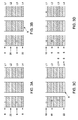
- FIGs. 3A to 3F illustrate cross-sectional view of a layer-by-layer arrangement of the substrate 10.
- An example of a substrate comprises four conductive layers and three non-conductive layers.
- the first, second, third, and fourth conductive layers are designated as L1, L2, L3, and L4 respectively.
- the 4 conductive layers are electrically insulated by 3 non-conductive layers.
- L1 and L3 comprise ion-sensing electrodes 6, wherein an intervening layer L2 is present that comprises a fence electrode 20.
- the fence electrode 20 prevents leakage of current between ion sensing electrodes.
- the L4 comprises heating element or heater 8.
- L1 and L3 are ion-sensing electrodes 6, wherein an intervening layer L2 is present as a fence electrode 20.
- the L4 comprises a temperature sensor 22.
- L1 and L2 comprise UV monitor 18, L3 and L4 comprise ion-sensing electrodes 6, and L4 further comprises a temperature sensor 22.
- L1 comprises an UV monitor 18, L2 and L4 comprise ion-sensing electrodes 6, wherein an intervening layer L3 comprises a heating element 8.
- L1 comprises an UV monitor 18, L2 comprises a heating element 8
- L3 comprises an ion-sensing electrode 6, and L4 comprises a temperature sensor 22.
- FIG. 3F is a cross-section view of one detector design, in which, the first conductor layer L1 is used as temperature sensor 22, the second layer L2 and third layer L3 are used as ion detector 6, and the fourth layer L4 is used as a heating element 8.
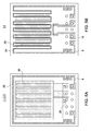
- FIGs. 4A and 4B are top view of the PID 1 having substrate with holes.
- the PID comprises an integrated circuit board 28.
- the layers of the substrate 10 are inter-connected to each other by holes 24 as shown in FIG 4A and 4B .
- the size of the hole is in a range of about 0.1 to 1 mm.
- a distance between edges of any of the two holes is 0.1 to 0.5 mm. In a specific embodiment, the distance between edges of any of the two holes is 0.3 mm.
- Each of the layers comprises one or more connecting pins 26.
- FIG. 4A shows three layers, L1, L2, and L3, wherein the heating elements or heaters are present on all three layers L1, L2, L3, and the heating elements are connected in series through holes.
- the heating element has a long serpentine design, and the length may be about 1m.
- FIG. 4B shows the layer L4, which comprises heating element 8, and a temperature feedback control circuit 16.
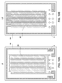
- FIGs. 5A and 5B are top view of the PID 1 having substrate with slot openings.
- the slots are rectangular in shape.
- the PID comprises an integrated circuit board 28.
- the layers of the substrate are inter-connected to each other by slot openings 30 as shown in FIG 5A and 5B .
- each of the slots has a length of 8 mm.
- the distance between an edge of the slot and the edge of the integrated circuit board is about 2 mm.
- Each of the layers comprises one or more connecting pins 26.
- the PID comprises an integrated circuit board 28, which has a length of 16 mm and width of 12 mm.
- FIG. 5A shows three layers, L1, L2, and L3, wherein the heating elements or heaters are present on all three layers L1, L2, L3, and the heating elements are connected in series through layer interconnects.
- FIG. 5B shows the layer L4 comprising heating element 8, and the temperature feedback control circuit 16.
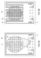
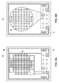
- FIGs. 6A to 6D are top view of the PID 1 comprising an integrated circuit board 28 with holes.
- the layers of the substrate are inter-connected to each other by holes 24.
- Each of the layers comprises one or more connecting pins 26.
- FIG. 6A, 6B , 6C, and 6D illustrate four different layers L1, L2, L3 and L4 respectively, wherein the heating elements or heaters are present on all four layers and the heating elements are connected in series through layer interconnects.
- FIG. 6D shows the layer L4, which further comprises the temperature feedback control circuit 16. Similar designs also exist with slot openings.
- FIG. 7A and 7B are top view of the PID 1 comprising an integrated circuit board 28 with holes.
- FIG. 7A shows three layers, L1, L2, and L3, wherein the heating elements or heaters are present on all three layers L1, L2, L3, and the heating elements are connected in series through layer interconnects.
- the heating element has a long serpentine design, and the length may be about 1m.
- FIG. 7B shows the layer L4, which comprises heating element 8, and the temperature feedback control circuit 16. Similar designs also exist with slot openings.
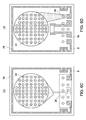
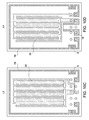
- FIGs. 8A to 8D are top view of the PID 1 comprising an integrated circuit board 28 with holes.
- FIGs. 8A, 8B , 8C, and 8D illustrate four different layers L1, L2, L3 and L4 respectively, wherein the heating elements or heaters are present on all four layers and the heating elements are connected in series through layer interconnects.
- L1, L2, L3 and L4 the heating elements also act as fence electrodes.
- the heating element has a long serpentine design, and the length may be about 1m.
- FIG. 8D shows the layer L4, which further comprises the temperature feedback control circuit 16.
- the electrodes in FIG. 8A are straight-line electrodes. Similar designs also exist with slot openings as shown in FIGs. 9A to 9D .
- FIGs. 10A to 10D Another set of examples of PIDs with various designs of integrated circuit boards are illustrated in FIGs. 10A to 10D .
- the design of FIGs 10A to 10D are same as mentioned above, however, the integrated circuit board 28 is longer than the previous one.
- the length of the integrated circuit board is about 38 mm, and width of about 12 mm.
- Measurements of the ionization current were performed with a pair of ion sensing electrode as shown in FIG. 5 . Ion current was converted to voltage by a transimpedance amplifier. The collected signal was analyzed using Labview software. Human breath tests were conducted to evaluate the functionality of the PID. During the breath sample tests, samples were collected from human through a bacteria filter mouthpiece (Vacumed MQ303) connected directly to the gas line. Water condensation may results from moisture present in breath. To avoid water condensation, the PID sensor chip was heated to about 80°C by an integrated on-chip heater.
- a gas diffuser plate was designed and implemented in the gas chamber immediately before the PID sensor.
- the "I" shaped diffuser splits the incoming gas into two side-streams and blocks direct impact of the gas flow on the sensor electrodes. Tests showed this method was able to reduce baseline voltage variation to about 6mV in 1 to 20 L/min flow rate range.
- FIG. 11 shows the calibration data of a PID sensor, and the signal peaks illustrate the output voltage of the sensor at different acetone concentrations, where a 10 eV UV lamp was used.
- 34, 36, 38 and 40 are the signal peaks for 0.1 ppm, 0.5 ppm, 1 ppm, and 2 ppm acetone concentration respectively.
- acetone is one of the most abundant endogenous compounds in human breath.
- An amount of acetone in healthy subjects is in a range of about 0.2-10 ppm, and acetone is higher in patients having uncontrolled diabetes.
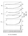
- the tests were performed by collecting samples from three different human individuals at two different times of a day. Two breath samples were collected from each human individual through a mouthpiece containing a bacteria filter (Vacuumed MQ303) connected directly to the gas line.
- the PID sensor was pre-heated to 79°C to prevent water condensation from human breath. One sample was collected about 1 hour before lunch and another sample was collected about 1 hour after lunch.
- the 5L sampling bag showed most consistent results compared to other two sampling approaches. Because of large volume, the 5L bag supplied a stable gas flow over a period of time to the PID to establish a steady signal output. In the direct blow and an approach with 0.25L bag, the sensor signal was seen dropping upon stopping of gas flow (stop blowing or empty bag). It is expected that when using a bag to collect breath sample, water vapor tend to condensate on the bag wall, which reduces the water concentration entering into the PID sensor chamber, therefore, reducing the water ion interference. This could explain the smaller signal amplitude with 5L and 0.25L bag sample. 0.25L sample has smallest signal amplitude. This is mainly due to the dead volume of the test setup.
- breath test signal and baseline is smaller than test data. This is because a lower UV lamp driving voltage is used (4 V down shift to 3.5 V) to extend the lifetime of the UV lamp. A lower driving voltage reduced the UV intensity emitted from the lamp, which changed the PID sensor sensitivity from 40mV/ppm to 10mv/ppm.
Landscapes
- Chemical & Material Sciences (AREA)
- Health & Medical Sciences (AREA)
- General Health & Medical Sciences (AREA)
- General Physics & Mathematics (AREA)
- Electrochemistry (AREA)
- Life Sciences & Earth Sciences (AREA)
- Analytical Chemistry (AREA)
- Biochemistry (AREA)
- Chemical Kinetics & Catalysis (AREA)
- Physics & Mathematics (AREA)
- Immunology (AREA)
- Pathology (AREA)
- Toxicology (AREA)
- Other Investigation Or Analysis Of Materials By Electrical Means (AREA)
- Investigating Or Analysing Materials By Optical Means (AREA)
- Investigating Or Analysing Biological Materials (AREA)
Abstract
Description
- The invention relates to volatile gas detectors and methods for detecting volatile gas components in breath, and more particularly to photo-ionization detectors and methods for detecting volatile gas components in breath using photo-ionization detectors.
- The volatile gas components present in a breath of an individual may reveal a health condition of the individual. For example, patients having diabetes, renal failure, or high cholesterol may have high concentrations of acetone, ammonia, or isoprene respectively in their breath. The reactive oxygen species oxidize polyunsaturated fatty acids, excreting lipid-based free radicals and eventually volatile alkanes and methylated alkanes in breath as markers for oxidative stress. Therefore, breath analysis is a way of screening patients for early detection of certain diseases by a reliable, noninvasive, painless, and inexpensive approach. The types and concentrations of chemical compounds that might serve as biomarkers for particular diseases can be determined by various methods, such as gas chromatography, laser spectrometry, ion mobility spectrometry, or sensor technologies such as electrochemical sensor, photo ionization sensor and semiconductor sensor. The latest advancement in breath analysis is to use photo ionization detector (PID) for screening patients having certain diseases.
- A typical PID includes an ionization source with high-energy photons, an ionization chamber, and an ion detector. The PID can detect volatile organic gases. In a PID, the high-energy photons are directed to the ionization chamber for collisions with gas molecules, wherein the photons ionize the gas molecules if the energy of the photon is larger than the ionization potential of the molecule. The ionized molecules are electrically detectable as ions and electrons.
- Although PID-based sensors may be used to correlate a response signal with a change in ionization, such response signals may be deleteriously affected by other, interfering signals, thereby generating signal artifacts. The signal artifacts may also include unwanted signal responses, for example, responses generated from one or more interfering molecules, such as water, ethanol, or carbon monoxide. The molecules are referred to herein as interfering substances, have high ionization potentials and can block or absorb UV photons, which decrease the detector sensitivity. A concern in prior PIDs is contaminants introduced with the sample and metal atoms released from internal and external electrodes which can deposit on the optical window of the UV lamp forming a coating and reduce the intensity of the UV light from the lamp. The coating reduces the sensitivity of the PID and requires recalibration of the PID using samples of known concentrations of detectable gas. Conventional PIDs also suffer from unstable baseline currents because of metallic electrodes, which are exposed to high-energy photons and release free electrons, which can produce a baseline current flow even when no ionizable gases are present. Frequent calibration of the PID with a reference is needed in order to re-establish a correct baseline current.
- Therefore, it is desirable to have a PID sensor, which can detect chemical components in breath with high selectivity and efficiency. The PID is desired to be energy efficient, can be miniaturized for portable applications, does not require frequent calibrations, and has a quick response to change in concentrations of volatile gases in surroundings.
- The invention relates to PID, and associated sensor systems that are capable of sensing volatile gases present in breath samples, and methods for making and using the sensors. The use of these PID or sensor system resolve the problems associated with the high selectivity and efficiency.
- In one embodiment, a photo-ionization detector (PID) comprises a substrate comprising a gas ionization chamber, at least one pair of ion sensing electrodes, and at least one amplifying circuit; and an ultraviolet (UV) ionization source to transmit a UV light beam into the gas ionization chamber.
- In another embodiment, a photo-ionization detector (PID) comprises a substrate, comprising a gas ionization chamber, at least one pair of ion sensing electrodes, and a heating element; an ultraviolet (UV) ionization source to transmit a UV light beam into the gas ionization chamber; a temperature sensor; and a temperature feedback control circuit in operative association with the substrate.
- In another embodiment, a system for measuring a compound in a gas mixture, comprises a photo-ionization detector (PID), a photo-ionization detector (PID) and a pressure sensor, wherein the PID comprises at least one ultraviolet (UV) ionization source and a substrate comprising a gas ionization chamber, at least one pair of ion sensing electrodes, and at least one amplifying circuit.
- In one example of a method of the invention, the method of measuring a compound in a breath sample by a photo-ionization detector (PID) comprises introducing the breath sample into the photo-ionization detector, transmitting an ultraviolet (UV) light beam through the breath sample; ionizing the breath sample; and detecting an amount of the compound in the breath sample.
- These and other features, aspects, and advantages of the present invention will become better understood when the following detailed description is read with reference to the accompanying drawings in which like characters represent like parts throughout the drawings, wherein:
-
FIG. 1 is a schematic drawing of a top view of a non-limiting embodiment of a photo-ionization detector (PID) of the invention, including an integrated current amplifier. -
FIG. 2 is a schematic drawing of a top view of a non-limiting embodiment of a PID of the invention, including an integrated heater and temperature sensor. -
FIGs. 3A to 3F are schematic drawings of cross-sectional views of substrates having layer-by-layer arrangement. -
FIG. 4A is a schematic drawing of the top view of one example of the PID substrate design comprising the first, second, and third layers with holes.FIG. 4B is a schematic drawing of the top view of the same PID substrate design comprising the fourth layer with holes. -
FIG. 5A is a schematic drawing of the top view of one example of the PID substrate design comprising the first, second, and third layers with slot openings.FIG. 5B is the top view of the same PID substrate design comprising the fourth layer with slot openings. -
FIGs. 6A to 6D are schematic drawings of the top view of one example of the PID substrate design comprising the first, second, third and fourth layers respectively with holes. -
FIG. 7A is a schematic drawing of the top view of one example of the PID substrate design comprising the first, second, and third layer with ion sensing electrodes stacked together.FIG. 7B is a schematic drawing of the top view of the same PID substrate design comprising the fourth layer with ion sensing electrodes stacked together. -
FIGs. 8A to 8D are schematic drawings of the top view of one example of the PID substrate design comprising the first, second, third and fourth layers with holes, and including a heater that functions as a fence electrode. -
FIGs. 9A to 9D are schematic drawings of the top view of one example of the PID substrate design comprising the first, second, third and fourth layers with slot openings, and including a heater that functions as a fence electrode. -
FIGs. 10A to 10D are schematic drawings of the top view of one example of the PID substrate design comprising the first, second, third and fourth layers with slot openings on a longer integrated circuit board, and including a heater at the second layer. -
FIG. 11 is a calibration graph of a PID of the invention. -
FIG. 12 is a graph of a signal output of a PID of the invention to measure various components of breath sample collected from three different subjects before food intake. - These and other features, aspects, and advantages of the present invention will become better understood when the following detailed description is read with reference to the accompanying drawings in which like characters represent like parts throughout the drawings, wherein:
- One or more of the embodiments of the PID are adapted to detect photo ionization of the volatile gases or compounds present in breath. In some embodiments, the PID may be used in a system.
- In one or more of the embodiments, the PID comprises a substrate comprising a gas ionization chamber, at least one pair of ion sensing electrodes, and at least one amplifying circuit; and an UV ionization source to transmit a UV light beam into the gas ionization chamber.
- The substrate further comprises a heating element. The heating element stabilizes the temperature of the PID and prevents condensation in the PID. The heating element may be a thin film heater, a heating pad, a solid-state heater, a filament heater, a heating tape, or any heater with a heating element. Generally, heating element maintains a nearly constant temperature of the ionization chamber of PID and prevents water condensation from entering gas. In a normal operation, heating element heats ionization chamber up to about 300° C, but any temperature (e.g., 40 to 50° C) that is above the temperature of the gas entering PID is sufficient to prevent condensation. In the absence of heating element, when PID is cooler than the ambient air, moistures may condense on optical window and electrodes. The condensation on optical window blocks UV light, and the condensation on electrodes causes a leakage current between electrodes. Heating element heats optical window and electrodes in ionization chamber to prevent condensation. In addition, heating element and temperature sensor can maintain PID at an optimal or constant operating temperature through a temperature feedback control loop and eliminate fluctuation of the baseline or zero signal of PID due to temperature variation. In one embodiment, the heating element and the ion sensing electrodes are integrated to the substrate.
- The substrate further comprises a temperature sensor. The temperature sensor is useful in sensing change of temperature in the PID. The substrate further comprises a temperature feedback control circuit. The temperature sensor, temperature feedback control circuit and heating element may be present in an operative association, so that when the temperature of PID is different from the desired operation temperature, an error signal is generated based on the temperature sensor's output and a temperature setpoint. The temperature feedback control circuit activates or turn off the heating element based on the error signal to maintain the temperature of the PID to a preset temperature point.
- In another embodiment, a PID comprises a substrate, comprising a gas ionization chamber, at least one pair of ion sensing electrodes, and a heating element; an UV ionization source to transmit a UV light beam into the gas ionization chamber; a temperature sensor; and a temperature feedback control circuit in operative association with the substrate. In this embodiment, the PID may further comprise an amplifying circuit.
- A pair of electrodes may be disposed on the substrate and may be coupled to the gas ionization chamber. In one embodiment, a pair of electrodes may be disposed on the amplifying circuit and may be coupled to the gas ionization chamber. Non-limiting examples of electrodes may include inter-digitated electrodes, ion sensing electrodes, photoemission electrodes, or discharge electrodes. In some embodiments, two pairs of electrodes may be present. Of the two pairs of electrodes, one pair may be used for measuring the ionized molecules, and the other pair may be used to monitor the photoemission current. The electrodes of ion detectors may have a variety of shapes. Non-limiting examples of electrode configuration may include interdigitated electrodes, combined electrodes, separated electrodes, parallel plate electrodes, monolayer electrodes, and multilayered electrodes. The multilayered electrode may comprise alternating conducting layers and dielectric layers. In some embodiments of the multilayered electrode, the electrode is made of plurality of conducting layers, or the electrode is made of plurality of dielectric layers. The substrate may further include one or more electrodes in between a pair of ion sensing electrodes to eliminate substrate current interference. This electrode used in between a pair of ion sensing electrodes, is also refers herein as a fence electrode. The fence electrode prevents ion-leakage between two ion-sensing electrodes.
- An interference results from a leakage current between two electrodes is known as 'substrate current interference'. In high voltage, the current leaks from the surface or edge of the electrodes. Two conductors are disposed on an insulating substrate to form the ion sensing electrodes. During sensing operation, a bias voltage is applied between the two electrodes to measure ion current (used herein as ion current measuring electrodes) of the gas sample. However, a leakage current may flow through the surface of the insulating substrate. The leakage current causes interference to the ion current. One method to reduce the leakage current is by using a third electrode in between the two ion sensing electrodes. By connecting the third electrode to ground or to a specific voltage source, leakage current may flow through the third electrode to the ground or to the specific voltage source instead of reaching the two measuring electrodes.
- The ion sensing electrodes attract positive ions formed when UV photons impact the ionizable gas molecules. An electrometer is present in operative association with the ion sensing electrodes. The ion sensing electrodes measure the ion current and the electrometer converts the ion current to a voltage, which is directly proportional to the concentration of ions. The concentration of the ions provides a measurement of equivalent amount of compounds present in the gas sample. The UV photons impact the photoemission electrode, which may liberate electrons but those electrons are typically attracted back to the photoemission electrode and do not contribute to a baseline current between the ion sensing electrodes. The photoemission electrode measures the electron number, which indicates the conditions of UV lamp.
- The substrate is made of one or more conducting layers, dielectric layers, or combinations of conducting layers and dielectric layers. The substrate is made of metal, ceramic, glass, polymer, or combinations thereof. In one embodiment, the substrate is made of semiconductor materials selected from the group consisting of silicon, germanium, silicon carbide, silicon nitride, aluminium nitride, aluminium phosphide, boron nitride, boron phosphide, and combinations thereof. The substrate may be, for example, a ceramic substrate, a printed circuit board, or a silicon substrate. The ceramic-based multilayer substrate may be formed by low temperature co-firing ceramic technology. In one embodiment, the substrate is a printed circuit board. Conducting layer deposition and patterning on the top surface of the substrate may form ion-sensing electrodes. The heating element may present on the top surface of the substrate, or on the bottom surface of the substrate. In one embodiment, the conducting layer of the substrate may function as the heating element.
- The substrate may be single layered, or multilayered. The multilayered substrate may comprise alternating conducting layers and dielectric (or non-conductive) layers. In some embodiments of the multilayered substrate comprise a plurality of conducting layers, or plurality of dielectric layers. The multilayered substrate may comprise a first layer, a second layer, a third layer, and a fourth layer. In a non-limiting embodiment, the substrate may comprise more than four layers. In one embodiment, the first layer of the substrate may comprise at least a pair of ion sensing electrodes, an amplification circuit, and at least one ionization chamber. The second layer of the substrate may comprise a pair of electrode connecting to the UV lamp, and a lamp holder that holds the UV lamp, which is connected to the substrate. In another embodiment, the first layer of the substrate may further comprise a heating element on the substrate. The first layer of the substrate may comprise a temperature sensor on the substrate. In some other embodiments, the second layer of the substrate may comprise a heating element and a temperature sensor on the substrate. The multilayered substrate may have one or more gaps or channels in between two or more conducting layers. The ionization chamber may form in one or more gaps or channels in between two dielectric layers on the substrate.
- The substrate comprises an array of holes or open slots. The holes or open slots provide open spaces to ionize the molecules, and configured as a gas ionization chamber. The holes or open slots are also function as connecting pins between various layers. The open slots are mainly rectangular in shape. In some embodiments, the substrate may comprise a plurality of layers, wherein the top and the bottom layers have holes or slot openings. In those embodiments, the middle layers have void spaces, which form a chamber for gas ionization. The gas passes through the holes or slot openings to the void spaces and UV light beam passes through the gas in perpendicular direction, which results ionization of the gas molecules. The gas ionization chamber may comprise ion-sensing electrodes to determine ion current. The gas ionization chamber further comprises a diffuser that regulates a controlled gas flow into the gas ionization chamber.
- The UV ionization source is an ultraviolet lamp (UV lamp), or a light emitting diode (LED). In one embodiment, the UV ionization source is directly fixed on the lamp driver board. The UV ionization source transmits UV light in a frequency range from about 100 nm to 210 nm. When an external electrical field excites the UV lamp, a UV radiation is produced, wherein the UV radiation may be in the form of a UV light beam. The UV light beam is directed into the gas ionization chamber perpendicular to a path of gas flow. In some embodiments, the UV ionization source is directly fixed to the substrate. In some embodiments, multiple UV lamps may be use to provide selectivity for various compounds present in the breath sample. Different compounds in breath have varying PID potentials therefore providing intrinsic selectivity by using low energy UV lamp, and/or using combinations of different UV lamps. The UV ionization source can selectively provide UV lights of more than one energy levels. The UV ionization source is selected from the UV lamp of 8.4 eV, 9.6 eV, 9.8 eV, 10 eV, 10.2 eV, 10.6 eV or 11.6 eV or a combination of more than one foregoing UV lamps. Different gas has different emission wavelengths, hence, different ionization energy. Typical inert gases used for UV lamp are krypton, xenon, and argon. For example, the krypton has ionization energy in a range from about 10 to 10.6 eV, xenon has ionization energy in a range from about 8.4 to 9.6 eV, and argon has ionization energy of 11.7 eV.
- A conventional gas discharge UV lamp for a PID is a sealed glass envelope containing two plates. A high voltage, which is applied to the plates via the leads that extend from the plates out of the glass envelope, causes a glow discharge process in a gas, which is trapped in the envelope. The glow discharge process generates UV photons that exit the envelope through an optical window and illuminate the ionization chamber of the PID.
- The UV ionization source ionizes the gas in the ionization chamber, and the ions are measured by ion sensing electrodes and generate a response signal. The response signal may be generated due to a change in ion concentrations on ion sensing electrodes and the response signal is detectable with respect to control. The extent of ionizations of various compounds is different with respect to ionization energy, and the ionization of the compounds generates ions, which result a response signal that represents different compounds.
- The PID further comprises a direct current (DC) voltage source. The DC voltage source generates a high voltage to the ion sensing electrodes. The ion sensing electrodes are connected to a high voltage DC source that provides a DC voltage of 10-200 V.
- A typical PID senses ions and generate a signal outputs on the order of pico-amperes to microamperes. In order to achieve accurate measurement of the small current, a current amplifier is used to amplify the signal to a large enough voltage signal, which may be recorded. The PID comprises at least one amplifying circuit, which amplifies the response signal generated by ion sensing electrodes to form amplified signals. The amplified signals are transmitted to a processor, wherein the processor may be present in operative association with the PID. The at least one amplifying circuit is selected from a transimpedance amplifying circuit, or a current-to-current amplifying circuit. A transimpedance amplifier converts current to voltage and amplify the signal. One way to make a transimpedance amplifier is to use a high gain operational amplifier with a resistive feedback. The feedback resistor determines the transimpedance gain. The bias voltage, such as Vb1 impact on the positive terminal of the operational amplifier and determines the baseline output voltage. In high sensitivity applications, a guard ring may be added to reduce stray leakage current from corrupting the signal going into the amplifier.
- The substrate may have a filtering circuit. The filtering circuit may reduce the measurement noise. The noise may be generated with the signal by substrate current interference, temperature variation, humidity interference, electromagnetic interference, capacitive coupling, inductive coupling, or other electrochemical interferences. To reduce the substrate current interference, one electrode of a pair of electrodes is attached to the ground or a voltage source, wherein the electrode eliminates the leakage current. A variation in temperature may generate a temperature-induced noise, which can be eliminated by using a temperature feedback control circuit. Using a heating element, the humidity-induced noise may be eliminated. The heating element maintains the inside temperature of the PID and reduce the condensation. Packaging the PID inside a metal shield may eliminate electromagnetic interference. Amplifier is used to minimize noise generated from capacitive coupling or inductive coupling. Positioning of amplifier in a close proximity of the ion sensing electrodes may reduce electrochemical or other interferences. When measuring low concentration target molecule in the sub ppb to ppm range, the ion current is very small. Any measurement noise or interference may affect the measurement of such small current. One method to reduce noise or interference is to have the amplifying circuit in close proximity of the ion sensing electrodes, which minimizes the coupling noise and interference. A significant noise reduction may generate a prominent and clear signal, which may provide an accurate measurement of ionized molecules of various compounds.
- The PID detects chemical compounds, volatile gases, or volatile organic compounds (VOCs) present in a gas mixture. For example, PID detects chemical compounds, volatile gases, or volatile organic compounds (VOCs) present in a breath sample. The PID is configured to detect aliphatic hydrocarbons, aromatic hydrocarbons, aldehydes, ketones, or alcohols. The PID is configured to detect acetone, isoprene, ammonia, ethanol, methanol, ethane, pentane or benzene. In a specific embodiment, the PID is configured to detect acetone. For selective detection of compounds in breath using PID, a combination of different UV lamps may be used while subtracting or compensating the contributions of interference of other compounds. The sampling method may be implemented such that only certain compounds are collected and introduced to PID detector to prevent interferences. The sampling method can be membrane based, pre-concentrator trap based, or other type of separation method, such as gas chromatography, or gas filters, however, some kinds of semi-separation method might also be useful. For example of a pre-concentrator trap based method, acetone can be trapped by Carbotrap X but larger molecules will not be trapped by this material. A different scenario can be that the analyte of interest may flow through the selected preconcentrator trap without being retained while most other interferents get trapped. For example, acetone will pass through the Carbotrap Y and Carbotrap B, which can trap a wide range of VOCs having carbon chain length from C5-C20.
- A system for measuring a compound in a gas mixture comprises a PID, and a pressure sensor. The system further comprises a processor configured to produce a sensor response pattern that indicates an amount of the compound in the gas mixture. The PID comprises a substrate, and an UV ionization source to transmit a UV light beam into the gas ionization chamber. The substrate comprises a gas ionization chamber, at least one pair of ion sensing electrodes, and at least one amplifying circuit. In an alternate embodiment, the system for measuring a compound in a gas mixture comprises a PID, a pressure sensor, and a processor, wherein the PID comprises a substrate. The substrate comprises an UV ionization source to transmit a UV light beam into the gas ionization chamber, a temperature sensor, and a temperature feedback control circuit in operative association with the substrate. In this embodiment, the substrate comprises a gas ionization chamber, at least one pair of ion sensing electrodes, and at least one heating element.
- An absolute pressure sensor with a pressure measuring range of 0-30 inch-water is used to measure pressure of breath sample. The use of pressure sensor ensures that the breath sample subjected to the PID has a proper blowing pattern with a constant pressure. A constant pressure is desirable during the measurement to generate accurate data. A differential pressure sensor with a range of 0-1 inch-water is used to measure the flow rate of breath sample based on differential pressure measurement at two locations in the PID. The purpose of the flow measurement is to ensure providing enough volume of breath to the PID for an accurate measurement. Typically, only the end tidal breath contains the right ion concentration, which may be captured by monitoring the flow rate of breath sample and PID signal after passing certain volume of breath sample. Depending on the age, physical condition, and other related parameters of the user, the initial dead volume of breath sample may be different. The system further comprises a diffuser that regulates a flow of the gas mixture. The diffuser is coupled to the gas ionization chamber. The at least one pair of ion sensing electrodes is an acetone sensing electrodes. The system further comprises a gas flow-rate sensor. The gas flow-rate sensor is configured to detect flow rate of gas while passing through gas ionization chamber.
- The system further comprises a CO2 sensor. CO2 measurement is an important aspect of breath analysis. The level of CO2 concentration determines various parameters in the system. For example, CO2 concentration determines whether the user breath may reach the end-tidal of the system. Desired CO2 concentration for end-tidal breath is around 5%. Therefore, a CO2 sensor may ensure the accurate end-tidal measurement. The second purpose for using CO2 sensor is to provide a normalization parameter to compare measured data between different subjects. Various subjects (human individual) have different metabolic rate and respiratory ventilation rate, resulting in different VOC concentration in breath. Therefore, it is hard to compare absolute VOC concentration data. However, if the concentration is normalized by breath CO2 concentration, then a comparison may be established in a large-scale database for breath analysis application.
- The system further comprises a controller, which is present in operative association with the PID. The controller mainly regulates the temperature feedback control unit, and the heating element depending on the temperature of the PID. The controller also controls the system by using heating element to reduce humidity and condensation.
- A method of measuring a compound in a breath sample by a PID, comprises collecting the breath sample; introducing the breath sample into the PID, transmitting an UV light beam through the breath sample, ionizing the breath sample, and detecting an amount of the compound in the breath sample. The method further generates a sensor response pattern. The sensor response pattern quantifies the amount of each compound present in the breath sample. The method further comprises heating the photo-ionization detector by using a heating element for maintaining a temperature inside the PID. The method further comprises measuring a temperature of the PID by a temperature sensor present in the PID. The method further controls a temperature-feedback control mechanism using the temperature sensor and the heating element.
- Referring now to
FIG. 1 andFIG. 2 , two different embodiments of a PID sensor 1 are illustrated. The PID sensor 1 employs anintegrated substrate structure 10 including theionization chamber 4, ion sensing electrodes ofPID 6, andheating element 8. In one embodiment, thesubstrate 10 is made of ceramic, with a thickness of at least 0.1 mm. The PID comprises an ultraviolet (UV)ionization source 2 to transmit a UV light beam into the gas ionization chamber. In the embodiment ofFIG. 1 , the PID comprises an amplifier or an amplifyingcircuit 12. In the embodiment ofFIG 2 , the PID comprises atemperature sensor 14, and a temperaturefeedback control unit 16. -
FIGs. 3A to 3F illustrate cross-sectional view of a layer-by-layer arrangement of thesubstrate 10. An example of a substrate comprises four conductive layers and three non-conductive layers. The first, second, third, and fourth conductive layers are designated as L1, L2, L3, and L4 respectively. The 4 conductive layers are electrically insulated by 3 non-conductive layers. InFIG. 3A , L1 and L3 comprise ion-sensing electrodes 6, wherein an intervening layer L2 is present that comprises afence electrode 20. Thefence electrode 20 prevents leakage of current between ion sensing electrodes. The L4 comprises heating element orheater 8. InFIG. 3B , L1 and L3 are ion-sensing electrodes 6, wherein an intervening layer L2 is present as afence electrode 20. The L4 comprises atemperature sensor 22. InFIG. 3C , L1 and L2 comprise UV monitor 18, L3 and L4 comprise ion-sensing electrodes 6, and L4 further comprises atemperature sensor 22. InFIG. 3D , L1 comprises anUV monitor 18, L2 and L4 comprise ion-sensing electrodes 6, wherein an intervening layer L3 comprises aheating element 8. InFIG. 3E , L1 comprises anUV monitor 18, L2 comprises aheating element 8, L3 comprises an ion-sensing electrode 6, and L4 comprises atemperature sensor 22.FIG. 3F is a cross-section view of one detector design, in which, the first conductor layer L1 is used astemperature sensor 22, the second layer L2 and third layer L3 are used asion detector 6, and the fourth layer L4 is used as aheating element 8. -
FIGs. 4A and 4B are top view of the PID 1 having substrate with holes. The PID comprises anintegrated circuit board 28. The layers of thesubstrate 10 are inter-connected to each other byholes 24 as shown inFIG 4A and 4B . The size of the hole is in a range of about 0.1 to 1 mm. A distance between edges of any of the two holes is 0.1 to 0.5 mm. In a specific embodiment, the distance between edges of any of the two holes is 0.3 mm. Each of the layers comprises one or more connecting pins 26.FIG. 4A shows three layers, L1, L2, and L3, wherein the heating elements or heaters are present on all three layers L1, L2, L3, and the heating elements are connected in series through holes. The heating element has a long serpentine design, and the length may be about 1m.FIG. 4B shows the layer L4, which comprisesheating element 8, and a temperaturefeedback control circuit 16. -
FIGs. 5A and 5B are top view of the PID 1 having substrate with slot openings. In one example, the slots are rectangular in shape. The PID comprises anintegrated circuit board 28. The layers of the substrate are inter-connected to each other byslot openings 30 as shown inFIG 5A and 5B . In one example, each of the slots has a length of 8 mm. In a specific embodiment, the distance between an edge of the slot and the edge of the integrated circuit board is about 2 mm. Each of the layers comprises one or more connecting pins 26. The PID comprises anintegrated circuit board 28, which has a length of 16 mm and width of 12 mm.FIG. 5A shows three layers, L1, L2, and L3, wherein the heating elements or heaters are present on all three layers L1, L2, L3, and the heating elements are connected in series through layer interconnects.FIG. 5B shows the layer L4 comprisingheating element 8, and the temperaturefeedback control circuit 16. -
FIGs. 6A to 6D are top view of the PID 1 comprising anintegrated circuit board 28 with holes. The layers of the substrate are inter-connected to each other byholes 24. Each of the layers comprises one or more connecting pins 26.FIG. 6A, 6B ,6C, and 6D illustrate four different layers L1, L2, L3 and L4 respectively, wherein the heating elements or heaters are present on all four layers and the heating elements are connected in series through layer interconnects.FIG. 6D shows the layer L4, which further comprises the temperaturefeedback control circuit 16. Similar designs also exist with slot openings. -
FIG. 7A and 7B are top view of the PID 1 comprising anintegrated circuit board 28 with holes.FIG. 7A shows three layers, L1, L2, and L3, wherein the heating elements or heaters are present on all three layers L1, L2, L3, and the heating elements are connected in series through layer interconnects. The heating element has a long serpentine design, and the length may be about 1m.FIG. 7B shows the layer L4, which comprisesheating element 8, and the temperaturefeedback control circuit 16. Similar designs also exist with slot openings. -
FIGs. 8A to 8D are top view of the PID 1 comprising anintegrated circuit board 28 with holes.FIGs. 8A, 8B ,8C, and 8D illustrate four different layers L1, L2, L3 and L4 respectively, wherein the heating elements or heaters are present on all four layers and the heating elements are connected in series through layer interconnects. In L1, L2, L3 and L4, the heating elements also act as fence electrodes. In layer L3, the heating element has a long serpentine design, and the length may be about 1m.FIG. 8D shows the layer L4, which further comprises the temperaturefeedback control circuit 16. The electrodes inFIG. 8A are straight-line electrodes. Similar designs also exist with slot openings as shown inFIGs. 9A to 9D . Another set of examples of PIDs with various designs of integrated circuit boards are illustrated inFIGs. 10A to 10D . The design ofFIGs 10A to 10D are same as mentioned above, however, theintegrated circuit board 28 is longer than the previous one. The length of the integrated circuit board is about 38 mm, and width of about 12 mm. - Measurements of the ionization current were performed with a pair of ion sensing electrode as shown in
FIG. 5 . Ion current was converted to voltage by a transimpedance amplifier. The collected signal was analyzed using Labview software. Human breath tests were conducted to evaluate the functionality of the PID. During the breath sample tests, samples were collected from human through a bacteria filter mouthpiece (Vacumed MQ303) connected directly to the gas line. Water condensation may results from moisture present in breath. To avoid water condensation, the PID sensor chip was heated to about 80°C by an integrated on-chip heater. - In human breath, the gas flow rate or pressure during breathing varies from person to person. Separate tests showed that the variation of breath flow rate in the range of 2∼15 L/min is possible. The change of flow rate affects the PID sensor's baseline signal (background signal when acetone is absent), leading to inaccuracy of ion measurement. Tests have indicated that the PID's baseline voltage could change ∼70mv when gas flow rate was varied from 1 to 20 L/min. The cause for the baseline change might partially because the incoming gas directly impacted on the lamp and sensor electrodes, which resulted a number of effects, such as abrupt changes of temperature, flow rate, relative position, and humidity in the ionization zone, one or the combination of which might result in change of sensor baseline voltage. To mitigate this issue, a gas diffuser plate was designed and implemented in the gas chamber immediately before the PID sensor. The "I" shaped diffuser splits the incoming gas into two side-streams and blocks direct impact of the gas flow on the sensor electrodes. Tests showed this method was able to reduce baseline voltage variation to about 6mV in 1 to 20 L/min flow rate range.
- For calibration, the PID sensor was subjected to dry acetone-nitrogen gas mixtures with different acetone concentrations.
FIG. 11 shows the calibration data of a PID sensor, and the signal peaks illustrate the output voltage of the sensor at different acetone concentrations, where a 10 eV UV lamp was used. 34, 36, 38 and 40 are the signal peaks for 0.1 ppm, 0.5 ppm, 1 ppm, and 2 ppm acetone concentration respectively. - In fat-metabolism, the decarboxylation of acetoacetate generates acetone, which is one of the most abundant endogenous compounds in human breath. An amount of acetone in healthy subjects is in a range of about 0.2-10 ppm, and acetone is higher in patients having uncontrolled diabetes. The tests were performed by collecting samples from three different human individuals at two different times of a day. Two breath samples were collected from each human individual through a mouthpiece containing a bacteria filter (Vacuumed MQ303) connected directly to the gas line. The PID sensor was pre-heated to 79°C to prevent water condensation from human breath. One sample was collected about 1 hour before lunch and another sample was collected about 1 hour after lunch.
FIG. 12 and Table 1 show the sensor response pattern (output voltage) for the breath acetone as detected by the PID. Comparing the signals obtained before (FIG. 12 ) and after (data not shown) lunch, as shown in Table 1, the breath acetone concentration was dropped about 20% after lunch, wherein the sensor output in Volts (in the plot ofFIG. 12 ) represents amount of acetone present in the breath sample in ppm. This result is consistent with the general understanding of the reduced fat metabolism after meal, wherein the amount of acetone is within a typical breath acetone range. The delayed drop (tail) of each signal peak may be due to the slow exiting residual gas in the gas line, which is about 5 feet (4mm I.D., ∼19 mL in volume) in the bench top setup for this test. As a result, the PID was able to quantify an amount of various compounds present in different gas mixture of the breath sample.Table 1 Subject Before lunch (mV) After lunch (mV) Change (mV) Change (%) Sample 1 Sample 2Average Sample 1 Sample 2Average 1 126 123 124.5 98 94 96 -28.5 -22.9% 2 114 103 108.5 96 76 86 -22.5 -20.7% 3 138 126 132 112 100 106 -26 -19.7% - In comparison, two commercially available PID sensors (for example, sensor 1 & 2), which were used as control, showed different levels of malfunction for human breath test (data not shown). The response pattern (or signal) of sensor 1 was unable to return to the baseline with time and the data was inconsistent between two different samples collected consecutively from the same human individual.
Sensor 2 showed slight drops from baseline when breath samples were provided, instead of positive signal peaks (data not shown). Sincesensors 1 and 2 functioned well in prior dry gas tests, the malfunction of the sensors for human breath sample is assumed due to the high humidity of human breath, which could condense and form conductive path between the sensor electrodes at room temperature. Therefore, the disclosed PID was able to quantify amount of various gases within acceptable margins of error. - Various breath-sampling approaches suitable for the PID were tested. In the experiment, three sampling methods were tested, such as, direct blow through a bacteria filter mouthpiece (Vacumed MQ303), pre-sampled breath stored in a 5L sampling bag (SKC), and pre-sampled breath stored in a 0.25L GaSampler bag (Quintron).
- The 5L sampling bag showed most consistent results compared to other two sampling approaches. Because of large volume, the 5L bag supplied a stable gas flow over a period of time to the PID to establish a steady signal output. In the direct blow and an approach with 0.25L bag, the sensor signal was seen dropping upon stopping of gas flow (stop blowing or empty bag). It is expected that when using a bag to collect breath sample, water vapor tend to condensate on the bag wall, which reduces the water concentration entering into the PID sensor chamber, therefore, reducing the water ion interference. This could explain the smaller signal amplitude with 5L and 0.25L bag sample. 0.25L sample has smallest signal amplitude. This is mainly due to the dead volume of the test setup. It is also noticeable that the breath test signal and baseline is smaller than test data. This is because a lower UV lamp driving voltage is used (4 V down shift to 3.5 V) to extend the lifetime of the UV lamp. A lower driving voltage reduced the UV intensity emitted from the lamp, which changed the PID sensor sensitivity from 40mV/ppm to 10mv/ppm.
- While only certain features of the invention have been illustrated and described herein, many modifications and changes will occur to those skilled in the art. It is, therefore, to be understood that the appended claims are intended to cover all such modifications and changes as fall within the scope of the invention.
- Various aspects and embodiments of the invention are indicated in the following clauses:
- 1. A photo-ionization detector (PID), comprising:
- a substrate comprising
- a gas ionization chamber,
- at least one pair of ion sensing electrodes,
- and at least one amplifying circuit; and
- at least one ultraviolet (UV) ionization source to transmit a UV light beam into the gas ionization chamber in the substrate.
- 2. The photo-ionization detector of clause 1, wherein the substrate further comprises a heating element.
- 3. The photo-ionization detector of either of
clause 1 or 2, wherein the substrate further comprises a temperature sensor. - 4. The photo-ionization detector of any preceding clause, wherein the substrate further comprises a temperature feedback control circuit.
- 5. The photo-ionization detector of any preceding clause, wherein the substrate is made of one or more conducting layers, dielectric layers, or combinations of conducting layers and dielectric layers.
- 6. The photo-ionization detector of any preceding clause, wherein the substrate is a printed circuit board.
- 7. The photo-ionization detector of any preceding clause, wherein the substrate comprises an array of holes or open slots.
- 8. The photo-ionization detector of any preceding clause, wherein the detector comprises a plurality of UV sources.
- 9. The photo-ionization detector of any preceding clause, wherein the ultraviolet (UV) ionization source is an ultraviolet lamp (UV lamp), or a light emitting diode (LED).
- 10. The photo-ionization detector of any preceding clause, wherein the UV light beam is directed into the gas ionization chamber perpendicular to the substrate.
- 11. The photo-ionization detector of any preceding clause, wherein the at least one amplifying circuit and the at least one pair of ion sensing electrodes incorporates an electrical guard ring to reduce leakage current signal.
- 12. The photo-ionization detector of any preceding clause, wherein the at least one amplifying circuit is selected from a transimpedance amplifying circuit, or current-to-current amplifying circuit.
- 13. The photo-ionization detector of any preceding clause, further comprising a direct current (DC) voltage source.
- 14. The photo-ionization detector of any preceding clause, further comprising a diffuser that regulates a gas flow into the gas ionization chamber.
- 15. A photo-ionization detector (PID), comprising:
- a substrate comprising
- a gas ionization chamber,
- at least one pair of ion sensing electrodes,
- and a heating element;
- an ultraviolet (UV) ionization source to transmit a UV light beam into the gas ionization chamber.
- 16. The photo-ionization detector of
clause 15, further comprises a temperature sensor, and a temperature feedback control circuit in operative association with the substrate. - 17. The photo-ionization detector of either of
clause - 18. The photo-ionization detector of any one of
clauses 15 to 17, is configured to detect acetone, isoprene, ammonia, or benzene. - 19. The photo-ionization detector of any one of
clauses 15 to 17, is configured to detect acetone. - 20. The photo-ionization detector of any one of
clauses 15 to 19, wherein the ultraviolet (UV) ionization source is directly fixed on the lamp driver board. - 21. The photo-ionization detector of any one of
clauses 15 to 20, wherein the ultraviolet (UV) ionization source transmits ultraviolet (UV) light in a frequency range from about 100 nm to 210 nm. - 22. A system comprising the photo-ionization detector of any one of the preceding clauses.
- 23. A system for measuring a compound in a gas mixture, comprising:
- a photo-ionization detector (PID) and a pressure sensor,
- wherein the PID comprises at least one ultraviolet (UV) ionization source and a substrate comprising a gas ionization chamber, at least one pair of ion sensing electrodes, and at least one amplifying circuit.
- 24. The system of clause 23, further comprising a processor configured to produce a sensor response pattern that indicates an amount of the compound in the gas mixture.
- 25. The system of either of
clause 23 or 24, further comprising a diffuser that regulates a flow of the gas mixture. - 26. The system of
clause 25, wherein the diffuser is coupled to the gas ionization chamber. - 27. The system of any one of clauses 23 to 26, wherein the at least one pair of ion sensing electrodes is an acetone sensing electrodes.
- 28. The system of any one of clauses 23 to 27, wherein the ultraviolet (UV) ionization source is directly fixed to the substrate.
- 29. The system of any one of clauses 23 to 28, wherein the ultraviolet (UV) ionization source is an UV lamp of 8.4 eV, 9.6 eV, 9.8 eV, 10 eV, 10.2 eV, 10.6 eV or 11.6 eV.
- 30. The system of any one of clauses 23 to 29, further comprising a gas flow-rate sensor.
- 31. The system of any one of clauses 23 to 30, further comprising a CO2 sensor.
- 32. The system of any one of clauses 23 to 31, further comprising a controller in operative association with the substrate.
- 33. A method of measuring a compound in a breath sample by a photo-ionization detector (PID), comprising:
- introducing the breath sample into the photo-ionization detector,
- transmitting an ultraviolet (UV) light beam through the breath sample;
- ionizing the breath sample; and
- detecting an amount of the compound in the breath sample.
- 34. The method of
clause 33, wherein the compound is selected from acetone, isoprene, ethanol, methanol, ammonia, ethane, or pentane. - 35. The method of either of
clause - 36. The method of any one of
clauses 33 to 35, wherein the step of introducing the breath sample comprises filtering one or more selected compounds of the breath sample. - 37. The method of any one of
clauses 33 to 36, wherein the compound is acetone. - 38. The method of any one of
clauses 33 to 37, further generating a sensor response pattern. - 39. The method of
clause 38, wherein the sensor response pattern quantifies the amount of the compound present in the breath sample. - 40. The method of any one of
clauses 33 to 39, further comprising heating the photo-ionization detector by using a heating element for maintaining a temperature inside the photo-ionization detector. - 41. The method of any one of
clauses 33 to 40, further comprising measuring a temperature of the photo-ionization detector by a temperature sensor present in the photo-ionization detector. - 42. The method of any one of
clauses 33 to 41, further controlling a temperature-feedback control mechanism using the temperature sensor and the heating element.
Claims (15)
- A photo-ionization detector (PID) (1), comprising:a substrate (10) comprisinga gas ionization chamber (4),at least one pair of ion sensing electrodes (6),and at least one amplifying circuit (12); andat least one ultraviolet (UV) ionization source (2) to transmit a UV light beam into the gas ionization chamber (4) in the substrate (10).
- The photo-ionization detector (1) of claim 1, wherein the substrate (10) further comprises a heating element (8).
- The photo-ionization detector (1) of either of claim 1 or 2, wherein the substrate (10) further comprises a temperature sensor (14).
- The photo-ionization detector (1) of any preceding claim, wherein the substrate further comprises a temperature feedback control circuit (16).
- The photo-ionization detector (1) of any preceding claim, wherein the at least one amplifying circuit (12) and the at least one pair of ion sensing electrodes (6) incorporates an electrical guard ring to reduce leakage current signal.
- A photo-ionization detector (PID) (1), comprising:a substrate (10) comprisinga gas ionization chamber (4),at least one pair of ion sensing electrodes (6),and a heating element (8);an ultraviolet (UV) ionization source (2) to transmit a UV light beam into the gas ionization chamber (4).
- The photo-ionization detector (1) of claim 6, further comprising a temperature sensor (14), and a temperature feedback control circuit (16) in operative association with the substrate (10).
- The photo-ionization detector (1) of either of claim 6 or 7, the detector configured to detect acetone.
- A system for measuring a compound in a gas mixture, comprising:a photo-ionization detector (PID) according to any one of the preceding claims (1) and a pressure sensor,
- The system of claim 9, further comprising a processor configured to produce a sensor response pattern that indicates an amount of the compound in the gas mixture.
- The system of either of claim 9 or 10, further comprising a diffuser, the diffuser being either or both of i) operable to regulate a flow of the gas mixture; and ii) coupled to the gas ionization chamber.
- A method of measuring a compound in a breath sample by a photo-ionization detector (PID) (1), comprising:introducing the breath sample into the photo-ionization detector,transmitting an ultraviolet (UV) light beam through the breath sample;ionizing the breath sample; anddetecting an amount of the compound in the breath sample.
- The method of claim 12, wherein the step of introducing the breath sample comprises pre-concentrating one or more selected compounds of the breath sample.
- The method of either of claim 12 or 13, wherein the step of introducing the breath sample comprises filtering one or more selected compounds of the breath sample.
- The method of any of claims 12 to 14, further controlling a temperature-feedback control mechanism using the temperature sensor and the heating element.
Applications Claiming Priority (1)
| Application Number | Priority Date | Filing Date | Title |
|---|---|---|---|
| US12/956,953 US8922219B2 (en) | 2010-11-30 | 2010-11-30 | Photo-ionization detectors and associated methods thereof |
Publications (2)
| Publication Number | Publication Date |
|---|---|
| EP2458375A1 true EP2458375A1 (en) | 2012-05-30 |
| EP2458375B1 EP2458375B1 (en) | 2017-08-30 |
Family
ID=45350412
Family Applications (1)
| Application Number | Title | Priority Date | Filing Date |
|---|---|---|---|
| EP11189472.1A Not-in-force EP2458375B1 (en) | 2010-11-30 | 2011-11-17 | Photo-ionization detectors and associated methods thereof |
Country Status (4)
| Country | Link |
|---|---|
| US (1) | US8922219B2 (en) |
| EP (1) | EP2458375B1 (en) |
| JP (1) | JP5923284B2 (en) |
| CN (1) | CN102565183B (en) |
Cited By (12)
| Publication number | Priority date | Publication date | Assignee | Title |
|---|---|---|---|---|
| CN103268897A (en) * | 2013-05-30 | 2013-08-28 | 吉林大学 | Ultraviolet detector of large-energy-gap oxide semiconductor thin film layer and with passivation function and preparation method thereof |
| CN103424466A (en) * | 2013-08-07 | 2013-12-04 | 华瑞科学仪器(上海)有限公司 | Ultraviolet lamp driving electrode of proportion integration differentiation (PID) sensor |
| CN103424465A (en) * | 2013-07-26 | 2013-12-04 | 华瑞科学仪器(上海)有限公司 | Intelligent PID sensor module |
| EP2745775A1 (en) * | 2012-12-18 | 2014-06-25 | General Electric Company | Device for measuring respiratory gas property, airway adapter and gas analyzing unit for respiratory gas analysis |
| GB2537361A (en) * | 2015-04-10 | 2016-10-19 | Ion Science Ltd | A Water Immersible Detector |
| GB2537881A (en) * | 2015-04-29 | 2016-11-02 | Ion Science Ltd | A method of operating a photoionisation detector to detect VOC's dissolved in water |
| WO2018022072A1 (en) * | 2016-07-29 | 2018-02-01 | Honeywell International Inc. | Photoionization detector automated zero level calibration |
| WO2019099044A1 (en) * | 2017-11-20 | 2019-05-23 | Honeywell International Inc. | Low profile ionization detector |
| WO2021007332A1 (en) * | 2019-07-09 | 2021-01-14 | Nanova Environmental, Inc. | Microchannel photoionization detector |
| EP3770595A1 (en) * | 2019-07-01 | 2021-01-27 | Honeywell International Inc. | Methods and systems for limiting water within a photoionization detector |
| US11162917B2 (en) | 2019-02-28 | 2021-11-02 | Honeywell International Inc. | Device for improving gas detection in photoionization detector |
| EP4459275A3 (en) * | 2023-04-14 | 2025-01-08 | Alphasense Limited | Photoionization detector |
Families Citing this family (48)
| Publication number | Priority date | Publication date | Assignee | Title |
|---|---|---|---|---|
| US9069035B2 (en) * | 2011-08-21 | 2015-06-30 | Dong Chen | Predicting LED parameters from electroluminescent semiconductor wafer testing |
| US20150226629A1 (en) * | 2012-09-04 | 2015-08-13 | Atonarp Inc. | System and method for leak inspection |
| TWI497102B (en) * | 2012-10-31 | 2015-08-21 | Iner Aec Executive Yuan | Ionization chamber with built-in temperature sensor |
| US9581585B2 (en) * | 2013-11-15 | 2017-02-28 | Western New England University | Breath acetone monitor and method of detecting breath acetone |
| EP3100024B1 (en) * | 2014-01-27 | 2020-09-09 | Cornell University | Integrated circuits based biosensors |
| EP3223702B1 (en) * | 2014-11-24 | 2023-01-11 | Université catholique de Louvain | Miniaturized device for determining a breathing pattern |
| KR102599775B1 (en) * | 2015-05-05 | 2023-11-07 | 더 리젠츠 오브 더 유니버시티 오브 미시건 | Microfluidic photoionization detector |
| KR101720572B1 (en) * | 2015-09-14 | 2017-03-29 | 연세대학교 산학협력단 | Sensor for Volatile Organic Compounds |
| CN109791130B (en) * | 2016-08-24 | 2021-07-13 | 密歇根大学董事会 | Miniaturized Discharge Photoionization Detector |
| CN107917951A (en) * | 2016-10-09 | 2018-04-17 | 岛津企业管理(中国)有限公司 | Photoionization detector |
| US10101298B1 (en) * | 2017-04-18 | 2018-10-16 | Broadsens Corp. | Photo ionization detector with self-calibration |
| CN110662959A (en) * | 2017-05-24 | 2020-01-07 | B·布莱恩·梅尔松根股份公司 | Drift tube for ion mobility spectrometer with integrated cluster capillary column |
| KR101815038B1 (en) | 2017-06-07 | 2018-01-05 | (주)센텍지엠아이 | Body fat burning measurement device |
| CN107228853A (en) * | 2017-06-26 | 2017-10-03 | 河北百强医用设备制造有限公司 | A kind of tidal air Volatile Organic Components automatic detection device and its method |
| WO2019084953A1 (en) * | 2017-11-02 | 2019-05-09 | 王健 | Ion counting detection device for tumor-related molecules, and using method therefor |
| CN107727731B (en) * | 2017-11-16 | 2023-12-22 | 哈尔滨东方报警设备开发有限公司 | High life photo ion gas detector |
| PL232385B1 (en) * | 2018-04-24 | 2019-06-28 | Akademia Gorniczo Hutnicza Im Stanislawa Staszica W Krakowie | Portable device intended for detection of biomarkers in exhaled air and method for detection of biomarkers in exhaled air |
| KR102785325B1 (en) * | 2018-08-23 | 2025-03-21 | 이명관 | Portable cancer diagnostic device using energy level |
| KR102094323B1 (en) * | 2018-08-23 | 2020-03-27 | 권민상 | Portable lung cancer diagnostic system using smartphone |
| KR102763800B1 (en) * | 2018-08-23 | 2025-02-07 | 이명관 | Portable Lung cancer diagnostic device using breath |
| KR102094322B1 (en) * | 2018-08-23 | 2020-03-27 | 권민상 | Lung cancer diagnostic sensor using breath |
| CN109884167B (en) * | 2019-03-26 | 2024-05-24 | 重庆邮电大学 | Ionization chamber and spiral path miniature photoionization detection device |
| CN111024803B (en) * | 2019-12-23 | 2025-09-05 | 北京华泰诺安探测技术有限公司 | An adjustable photoionization sensor |
| KR102336622B1 (en) * | 2020-02-05 | 2021-12-09 | 주식회사 태성환경연구소 | VOC Sensing PID Gas Sensor Device |
| US12269315B2 (en) | 2020-08-20 | 2025-04-08 | Denso International America, Inc. | Systems and methods for measuring and managing odor brought into rental vehicles |
| US11881093B2 (en) | 2020-08-20 | 2024-01-23 | Denso International America, Inc. | Systems and methods for identifying smoking in vehicles |
| US12017506B2 (en) | 2020-08-20 | 2024-06-25 | Denso International America, Inc. | Passenger cabin air control systems and methods |
| US11760169B2 (en) | 2020-08-20 | 2023-09-19 | Denso International America, Inc. | Particulate control systems and methods for olfaction sensors |
| US12377711B2 (en) | 2020-08-20 | 2025-08-05 | Denso International America, Inc. | Vehicle feature control systems and methods based on smoking |
| US11760170B2 (en) | 2020-08-20 | 2023-09-19 | Denso International America, Inc. | Olfaction sensor preservation systems and methods |
| US11813926B2 (en) | 2020-08-20 | 2023-11-14 | Denso International America, Inc. | Binding agent and olfaction sensor |
| US12251991B2 (en) | 2020-08-20 | 2025-03-18 | Denso International America, Inc. | Humidity control for olfaction sensors |
| US11932080B2 (en) | 2020-08-20 | 2024-03-19 | Denso International America, Inc. | Diagnostic and recirculation control systems and methods |
| US11636870B2 (en) | 2020-08-20 | 2023-04-25 | Denso International America, Inc. | Smoking cessation systems and methods |
| US11828210B2 (en) | 2020-08-20 | 2023-11-28 | Denso International America, Inc. | Diagnostic systems and methods of vehicles using olfaction |
| CN114624321A (en) * | 2020-12-09 | 2022-06-14 | 中国科学院大连化学物理研究所 | High-sensitivity exhaled air detection device for acetone enrichment |
| WO2022130184A1 (en) * | 2020-12-14 | 2022-06-23 | Molex, Llc | Photoionization detector and method of operating same |
| CN112834490B (en) * | 2021-01-07 | 2022-12-20 | 上海雷密传感技术有限公司 | Photo-ion detection device |
| US11143619B1 (en) * | 2021-04-12 | 2021-10-12 | Nanova Environmental, Inc. | Photo-ionization device with improved linearity and stability |
| CN113504179B (en) * | 2021-07-07 | 2025-04-29 | 中国科学院广州地球化学研究所 | A PID sensor and a VOCs concentration measurement method |
| KR102539118B1 (en) * | 2021-08-19 | 2023-06-02 | 한국광기술원 | Photoionization Detector |
| CN114113293B (en) * | 2021-10-28 | 2023-10-20 | 汉威科技集团股份有限公司 | Photo-ionization detector active sensitivity compensation method, detector and detector |
| KR102611218B1 (en) | 2021-11-22 | 2023-12-08 | 한국전자기술연구원 | Photoionization gas sensor |
| CN114235942B (en) * | 2021-12-31 | 2025-03-25 | 北京华泰诺安技术有限公司 | A vacuum ultraviolet lamp structure and preparation method thereof, and photoionization sensor |
| EP4231005B1 (en) * | 2022-02-18 | 2025-08-27 | Dräger Safety AG & Co. KGaA | Photo-ionization detector (pid) including a plurality of measurement cells and method using such a pid |
| CN118641616A (en) * | 2023-03-13 | 2024-09-13 | 霍尼韦尔国际公司 | Photoionization detector and method of using the same |
| US12461066B2 (en) | 2023-06-27 | 2025-11-04 | Applications Uniques Ltd. | Condensation mitigation in ionization sensing |
| WO2025072176A1 (en) * | 2023-09-28 | 2025-04-03 | The Regents Of The University Of Michigan | Avalanche gas ionization detector |
Citations (4)
| Publication number | Priority date | Publication date | Assignee | Title |
|---|---|---|---|---|
| EP0573060A2 (en) * | 1992-06-03 | 1993-12-08 | Hideo Ueda | Expired air examination device and method for clinical purpose |
| US6313638B1 (en) * | 1999-03-17 | 2001-11-06 | Rae Systems, Inc. | Dual-channel photo-ionization detector that eliminates the effect of ultraviolet intensity on concentration measurements |
| EP1331477A2 (en) * | 2002-01-24 | 2003-07-30 | Mocon, Inc. | Plug-in photoionization sensor |
| EP2148194A1 (en) * | 2008-07-21 | 2010-01-27 | SLS Micro Technology GmbH | Photo ionization detector based on microsystems technology and production process therefor |
Family Cites Families (18)
| Publication number | Priority date | Publication date | Assignee | Title |
|---|---|---|---|---|
| US4398152A (en) | 1980-08-12 | 1983-08-09 | Leveson Richard C | Photoionization detector |
| US4377749A (en) | 1981-02-25 | 1983-03-22 | Young Robert A | Photoionizer |
| GB8414311D0 (en) | 1984-06-05 | 1984-07-11 | Lovelock J E | Gas chromatography |
| US4804846A (en) | 1987-12-04 | 1989-02-14 | O. I. Corporation | Photoionization detector for gas chromatography |
| JPH0647047A (en) * | 1992-06-03 | 1994-02-22 | Hideo Ueda | Method for clinical inspection of expiration and device therefor |
| US5578271A (en) * | 1995-03-01 | 1996-11-26 | O.I. Corporation | Tandem photoionization detector and halogen specific detector |
| US5855850A (en) * | 1995-09-29 | 1999-01-05 | Rosemount Analytical Inc. | Micromachined photoionization detector |
| JPH09243627A (en) * | 1996-03-04 | 1997-09-19 | Suzuki Motor Corp | Exhalation analyzer |
| US5773833A (en) | 1996-03-22 | 1998-06-30 | Rae Systems, Inc. | Photo-ionization detector for volatile gas measurement |
| US6225633B1 (en) | 1998-10-22 | 2001-05-01 | Rae Systems, Inc. | Photo-ionization detector for volatile gas measurement and a method for self-cleaning the same |
| US6612306B1 (en) * | 1999-10-13 | 2003-09-02 | Healthetech, Inc. | Respiratory nitric oxide meter |
| DE60222304T2 (en) | 2001-11-20 | 2008-06-05 | Ion Science Ltd., Cambridge | GASPHOTOIONISATIONSDETEKTOR |
| US7530257B2 (en) | 2002-09-27 | 2009-05-12 | Honeywell International Inc. | Phased micro analyzer VIII |
| US20080314115A1 (en) * | 2005-03-18 | 2008-12-25 | Zenics Limited | Compliance Apparatus |
| CN2854570Y (en) * | 2005-12-27 | 2007-01-03 | 天津中和科技有限公司 | Gas-flow proportional counter tube gas density monitor |
| US8002712B2 (en) * | 2006-01-26 | 2011-08-23 | Meka Vikas V | Breath and breath condensate analysis system and associated methods |
| US20080176317A1 (en) * | 2006-04-17 | 2008-07-24 | Kirollos Kirollos S | System and device for transformation and detection of substances |
| CN101504388A (en) * | 2009-03-16 | 2009-08-12 | 中北大学 | Miniature optical ionization sensor |
-
2010
- 2010-11-30 US US12/956,953 patent/US8922219B2/en not_active Expired - Fee Related
-
2011
- 2011-11-17 EP EP11189472.1A patent/EP2458375B1/en not_active Not-in-force
- 2011-11-24 JP JP2011255669A patent/JP5923284B2/en not_active Expired - Fee Related
- 2011-11-30 CN CN201110403148.6A patent/CN102565183B/en not_active Expired - Fee Related
Patent Citations (4)
| Publication number | Priority date | Publication date | Assignee | Title |
|---|---|---|---|---|
| EP0573060A2 (en) * | 1992-06-03 | 1993-12-08 | Hideo Ueda | Expired air examination device and method for clinical purpose |
| US6313638B1 (en) * | 1999-03-17 | 2001-11-06 | Rae Systems, Inc. | Dual-channel photo-ionization detector that eliminates the effect of ultraviolet intensity on concentration measurements |
| EP1331477A2 (en) * | 2002-01-24 | 2003-07-30 | Mocon, Inc. | Plug-in photoionization sensor |
| EP2148194A1 (en) * | 2008-07-21 | 2010-01-27 | SLS Micro Technology GmbH | Photo ionization detector based on microsystems technology and production process therefor |
Non-Patent Citations (1)
| Title |
|---|
| XIE Z ET AL: "Determination of acetone, 2-butanone, diethyl ketone and BTX using HSCC-UV-IMS", ANALYTICAL AND BIOANALYTICAL CHEMISTRY, vol. 372, no. 5-6, March 2002 (2002-03-01), pages 606 - 610, XP055023768, ISSN: 1618-2642, DOI: 10.1007/s00216-002-1248-4 * |
Cited By (29)
| Publication number | Priority date | Publication date | Assignee | Title |
|---|---|---|---|---|
| EP2745775A1 (en) * | 2012-12-18 | 2014-06-25 | General Electric Company | Device for measuring respiratory gas property, airway adapter and gas analyzing unit for respiratory gas analysis |
| CN103268897B (en) * | 2013-05-30 | 2015-11-04 | 吉林大学 | There is ultraviolet detector and the preparation method of the broad stopband oxide semiconductor thin film of Passivation Treatment |
| CN103268897A (en) * | 2013-05-30 | 2013-08-28 | 吉林大学 | Ultraviolet detector of large-energy-gap oxide semiconductor thin film layer and with passivation function and preparation method thereof |
| CN103424465A (en) * | 2013-07-26 | 2013-12-04 | 华瑞科学仪器(上海)有限公司 | Intelligent PID sensor module |
| CN103424465B (en) * | 2013-07-26 | 2016-05-18 | 华瑞科学仪器(上海)有限公司 | Intelligent PID sensor assembly |
| CN103424466A (en) * | 2013-08-07 | 2013-12-04 | 华瑞科学仪器(上海)有限公司 | Ultraviolet lamp driving electrode of proportion integration differentiation (PID) sensor |
| CN103424466B (en) * | 2013-08-07 | 2016-01-20 | 华瑞科学仪器(上海)有限公司 | The uviol lamp drive electrode of PID sensor |
| US10345265B2 (en) | 2015-04-10 | 2019-07-09 | Ion Science Limited | Water immersible detector |
| GB2537361A (en) * | 2015-04-10 | 2016-10-19 | Ion Science Ltd | A Water Immersible Detector |
| GB2537361B (en) * | 2015-04-10 | 2017-05-03 | Ion Science Ltd | A Water Immersible Detector |
| GB2537881A (en) * | 2015-04-29 | 2016-11-02 | Ion Science Ltd | A method of operating a photoionisation detector to detect VOC's dissolved in water |
| US11480554B2 (en) | 2016-07-29 | 2022-10-25 | Honeywell International Inc. | Photoionization detector automated zero level calibration |
| US11714073B2 (en) | 2016-07-29 | 2023-08-01 | Honeywell International Inc. | Photoionization detector automated zero level calibration |
| US10782273B2 (en) | 2016-07-29 | 2020-09-22 | Honeywell International Inc. | Photoionization detector automated zero level calibration |
| EP4435429A3 (en) * | 2016-07-29 | 2024-12-18 | Honeywell International Inc. | Photoionization detector automated zero level calibration |
| WO2018022072A1 (en) * | 2016-07-29 | 2018-02-01 | Honeywell International Inc. | Photoionization detector automated zero level calibration |
| US10969371B2 (en) | 2016-07-29 | 2021-04-06 | Honeywell International Inc. | Photoionization detector automated zero level calibration |
| EP3835783A1 (en) * | 2016-07-29 | 2021-06-16 | Honeywell International Inc. | Photoionization detector automated zero level calibration |
| US11346806B2 (en) | 2017-11-20 | 2022-05-31 | Honeywell International Inc. | Low profile ionization detector |
| WO2019099044A1 (en) * | 2017-11-20 | 2019-05-23 | Honeywell International Inc. | Low profile ionization detector |
| US11162917B2 (en) | 2019-02-28 | 2021-11-02 | Honeywell International Inc. | Device for improving gas detection in photoionization detector |
| US11604163B2 (en) | 2019-02-28 | 2023-03-14 | Honeywell International Inc. | Device for improving gas detection in photoionization detector |
| US11965855B2 (en) | 2019-02-28 | 2024-04-23 | Honeywell International Inc. | Device for improving gas detection in photoionization detector |
| EP3770595A1 (en) * | 2019-07-01 | 2021-01-27 | Honeywell International Inc. | Methods and systems for limiting water within a photoionization detector |
| EP4215910A1 (en) * | 2019-07-01 | 2023-07-26 | Honeywell International Inc. | Methods and systems for limiting water within a photoionization detector |
| US11782036B2 (en) | 2019-07-01 | 2023-10-10 | Honeywell International Inc. | Methods and systems for limiting water within a photoionization detector |
| CN114207428A (en) * | 2019-07-09 | 2022-03-18 | 纳华环境科技有限公司 | Micro-channel photoionization detector |
| WO2021007332A1 (en) * | 2019-07-09 | 2021-01-14 | Nanova Environmental, Inc. | Microchannel photoionization detector |
| EP4459275A3 (en) * | 2023-04-14 | 2025-01-08 | Alphasense Limited | Photoionization detector |
Also Published As
| Publication number | Publication date |
|---|---|
| US20120136268A1 (en) | 2012-05-31 |
| JP2012118063A (en) | 2012-06-21 |
| EP2458375B1 (en) | 2017-08-30 |
| CN102565183B (en) | 2016-04-13 |
| US8922219B2 (en) | 2014-12-30 |
| CN102565183A (en) | 2012-07-11 |
| JP5923284B2 (en) | 2016-05-24 |
Similar Documents
| Publication | Publication Date | Title |
|---|---|---|
| EP2458375B1 (en) | Photo-ionization detectors and associated methods thereof | |
| US10067108B2 (en) | Device for detecting volatile organic compounds | |
| JP3793757B2 (en) | Plug-in photoionization sensor | |
| EP2634556B1 (en) | Sampling apparatus | |
| CN111587375B (en) | Thin Ionization Detector | |
| US7174766B2 (en) | Calibration device for carbon dioxide sensor | |
| TW200937487A (en) | Chemical ionization reaction or proton transfer reaction mass spectrometry with a quadrupole or time-of-flight mass spectrometer | |
| Pan et al. | Quantitative detection of nitric oxide in exhaled human breath by extractive electrospray ionization mass spectrometry | |
| US20150377844A1 (en) | Discharge ionization current detector | |
| Yang et al. | Ultrasensitive detection of volatile aldehydes with chemi-ionization-coupled time-of-flight mass spectrometry | |
| US20240345041A1 (en) | Photoionization detector | |
| JP6786918B2 (en) | Gas sensor array, gas measuring device, and gas measuring method | |
| Uthra et al. | Infrared Non‐Invasive Exhaled Biomarker Sensing: A Review | |
| US20110097812A1 (en) | Gas detector and process for monitoring the concentration of a gas | |
| Mikoviny et al. | Development and characterization of a high-temperature proton-transfer-reaction mass spectrometer (HT-PTR-MS) | |
| CN118033013B (en) | A device for detecting components of human breath | |
| US5874314A (en) | Method for detecting organic vapors and aerosols | |
| CN222529280U (en) | On-line Photoionization Detector System for Measuring Volatile Organic Compounds | |
| CN118518745B (en) | High-sensitivity micro-channel photoionization detector | |
| WO2012099564A1 (en) | Detector having a single source for ionization and photo detection | |
| RU174543U1 (en) | Photoionization gas detector | |
| US12461066B2 (en) | Condensation mitigation in ionization sensing | |
| JPH09184829A (en) | Gas chromatograph | |
| JP5946111B2 (en) | Detection method and detection apparatus using plasma | |
| Pham et al. | Analytical approaches for disease detection |
Legal Events
| Date | Code | Title | Description |
|---|---|---|---|
| PUAI | Public reference made under article 153(3) epc to a published international application that has entered the european phase |
Free format text: ORIGINAL CODE: 0009012 |
|
| AK | Designated contracting states |
Kind code of ref document: A1 Designated state(s): AL AT BE BG CH CY CZ DE DK EE ES FI FR GB GR HR HU IE IS IT LI LT LU LV MC MK MT NL NO PL PT RO RS SE SI SK SM TR |
|
| AX | Request for extension of the european patent |
Extension state: BA ME |
|
| 17P | Request for examination filed |
Effective date: 20121130 |
|
| 17Q | First examination report despatched |
Effective date: 20161028 |
|
| GRAP | Despatch of communication of intention to grant a patent |
Free format text: ORIGINAL CODE: EPIDOSNIGR1 |
|
| INTG | Intention to grant announced |
Effective date: 20170530 |
|
| GRAS | Grant fee paid |
Free format text: ORIGINAL CODE: EPIDOSNIGR3 |
|
| GRAA | (expected) grant |
Free format text: ORIGINAL CODE: 0009210 |
|
| AK | Designated contracting states |
Kind code of ref document: B1 Designated state(s): AL AT BE BG CH CY CZ DE DK EE ES FI FR GB GR HR HU IE IS IT LI LT LU LV MC MK MT NL NO PL PT RO RS SE SI SK SM TR |
|
| REG | Reference to a national code |
Ref country code: GB Ref legal event code: FG4D |
|
| REG | Reference to a national code |
Ref country code: CH Ref legal event code: EP |
|
| REG | Reference to a national code |
Ref country code: AT Ref legal event code: REF Ref document number: 924043 Country of ref document: AT Kind code of ref document: T Effective date: 20170915 |
|
| REG | Reference to a national code |
Ref country code: IE Ref legal event code: FG4D |
|
| REG | Reference to a national code |
Ref country code: DE Ref legal event code: R096 Ref document number: 602011041036 Country of ref document: DE |
|
| REG | Reference to a national code |
Ref country code: NL Ref legal event code: MP Effective date: 20170830 |
|
| REG | Reference to a national code |
Ref country code: LT Ref legal event code: MG4D |
|
| REG | Reference to a national code |
Ref country code: AT Ref legal event code: MK05 Ref document number: 924043 Country of ref document: AT Kind code of ref document: T Effective date: 20170830 |
|
| PG25 | Lapsed in a contracting state [announced via postgrant information from national office to epo] |
Ref country code: HR Free format text: LAPSE BECAUSE OF FAILURE TO SUBMIT A TRANSLATION OF THE DESCRIPTION OR TO PAY THE FEE WITHIN THE PRESCRIBED TIME-LIMIT Effective date: 20170830 Ref country code: AT Free format text: LAPSE BECAUSE OF FAILURE TO SUBMIT A TRANSLATION OF THE DESCRIPTION OR TO PAY THE FEE WITHIN THE PRESCRIBED TIME-LIMIT Effective date: 20170830 Ref country code: FI Free format text: LAPSE BECAUSE OF FAILURE TO SUBMIT A TRANSLATION OF THE DESCRIPTION OR TO PAY THE FEE WITHIN THE PRESCRIBED TIME-LIMIT Effective date: 20170830 Ref country code: NO Free format text: LAPSE BECAUSE OF FAILURE TO SUBMIT A TRANSLATION OF THE DESCRIPTION OR TO PAY THE FEE WITHIN THE PRESCRIBED TIME-LIMIT Effective date: 20171130 Ref country code: SE Free format text: LAPSE BECAUSE OF FAILURE TO SUBMIT A TRANSLATION OF THE DESCRIPTION OR TO PAY THE FEE WITHIN THE PRESCRIBED TIME-LIMIT Effective date: 20170830 Ref country code: LT Free format text: LAPSE BECAUSE OF FAILURE TO SUBMIT A TRANSLATION OF THE DESCRIPTION OR TO PAY THE FEE WITHIN THE PRESCRIBED TIME-LIMIT Effective date: 20170830 |
|
| PG25 | Lapsed in a contracting state [announced via postgrant information from national office to epo] |
Ref country code: LV Free format text: LAPSE BECAUSE OF FAILURE TO SUBMIT A TRANSLATION OF THE DESCRIPTION OR TO PAY THE FEE WITHIN THE PRESCRIBED TIME-LIMIT Effective date: 20170830 Ref country code: ES Free format text: LAPSE BECAUSE OF FAILURE TO SUBMIT A TRANSLATION OF THE DESCRIPTION OR TO PAY THE FEE WITHIN THE PRESCRIBED TIME-LIMIT Effective date: 20170830 Ref country code: IS Free format text: LAPSE BECAUSE OF FAILURE TO SUBMIT A TRANSLATION OF THE DESCRIPTION OR TO PAY THE FEE WITHIN THE PRESCRIBED TIME-LIMIT Effective date: 20171230 Ref country code: GR Free format text: LAPSE BECAUSE OF FAILURE TO SUBMIT A TRANSLATION OF THE DESCRIPTION OR TO PAY THE FEE WITHIN THE PRESCRIBED TIME-LIMIT Effective date: 20171201 Ref country code: BG Free format text: LAPSE BECAUSE OF FAILURE TO SUBMIT A TRANSLATION OF THE DESCRIPTION OR TO PAY THE FEE WITHIN THE PRESCRIBED TIME-LIMIT Effective date: 20171130 Ref country code: RS Free format text: LAPSE BECAUSE OF FAILURE TO SUBMIT A TRANSLATION OF THE DESCRIPTION OR TO PAY THE FEE WITHIN THE PRESCRIBED TIME-LIMIT Effective date: 20170830 |
|
| PG25 | Lapsed in a contracting state [announced via postgrant information from national office to epo] |
Ref country code: NL Free format text: LAPSE BECAUSE OF FAILURE TO SUBMIT A TRANSLATION OF THE DESCRIPTION OR TO PAY THE FEE WITHIN THE PRESCRIBED TIME-LIMIT Effective date: 20170830 |
|
| PG25 | Lapsed in a contracting state [announced via postgrant information from national office to epo] |
Ref country code: RO Free format text: LAPSE BECAUSE OF FAILURE TO SUBMIT A TRANSLATION OF THE DESCRIPTION OR TO PAY THE FEE WITHIN THE PRESCRIBED TIME-LIMIT Effective date: 20170830 Ref country code: PL Free format text: LAPSE BECAUSE OF FAILURE TO SUBMIT A TRANSLATION OF THE DESCRIPTION OR TO PAY THE FEE WITHIN THE PRESCRIBED TIME-LIMIT Effective date: 20170830 Ref country code: CZ Free format text: LAPSE BECAUSE OF FAILURE TO SUBMIT A TRANSLATION OF THE DESCRIPTION OR TO PAY THE FEE WITHIN THE PRESCRIBED TIME-LIMIT Effective date: 20170830 Ref country code: DK Free format text: LAPSE BECAUSE OF FAILURE TO SUBMIT A TRANSLATION OF THE DESCRIPTION OR TO PAY THE FEE WITHIN THE PRESCRIBED TIME-LIMIT Effective date: 20170830 |
|
| PG25 | Lapsed in a contracting state [announced via postgrant information from national office to epo] |
Ref country code: SM Free format text: LAPSE BECAUSE OF FAILURE TO SUBMIT A TRANSLATION OF THE DESCRIPTION OR TO PAY THE FEE WITHIN THE PRESCRIBED TIME-LIMIT Effective date: 20170830 Ref country code: EE Free format text: LAPSE BECAUSE OF FAILURE TO SUBMIT A TRANSLATION OF THE DESCRIPTION OR TO PAY THE FEE WITHIN THE PRESCRIBED TIME-LIMIT Effective date: 20170830 Ref country code: IT Free format text: LAPSE BECAUSE OF FAILURE TO SUBMIT A TRANSLATION OF THE DESCRIPTION OR TO PAY THE FEE WITHIN THE PRESCRIBED TIME-LIMIT Effective date: 20170830 Ref country code: SK Free format text: LAPSE BECAUSE OF FAILURE TO SUBMIT A TRANSLATION OF THE DESCRIPTION OR TO PAY THE FEE WITHIN THE PRESCRIBED TIME-LIMIT Effective date: 20170830 |
|
| REG | Reference to a national code |
Ref country code: DE Ref legal event code: R097 Ref document number: 602011041036 Country of ref document: DE |
|
| PG25 | Lapsed in a contracting state [announced via postgrant information from national office to epo] |
Ref country code: MC Free format text: LAPSE BECAUSE OF FAILURE TO SUBMIT A TRANSLATION OF THE DESCRIPTION OR TO PAY THE FEE WITHIN THE PRESCRIBED TIME-LIMIT Effective date: 20170830 |
|
| PLBE | No opposition filed within time limit |
Free format text: ORIGINAL CODE: 0009261 |
|
| STAA | Information on the status of an ep patent application or granted ep patent |
Free format text: STATUS: NO OPPOSITION FILED WITHIN TIME LIMIT |
|
| GBPC | Gb: european patent ceased through non-payment of renewal fee |
Effective date: 20171130 |
|
| PG25 | Lapsed in a contracting state [announced via postgrant information from national office to epo] |
Ref country code: LI Free format text: LAPSE BECAUSE OF NON-PAYMENT OF DUE FEES Effective date: 20171130 Ref country code: CH Free format text: LAPSE BECAUSE OF NON-PAYMENT OF DUE FEES Effective date: 20171130 |
|
| 26N | No opposition filed |
Effective date: 20180531 |
|
| PG25 | Lapsed in a contracting state [announced via postgrant information from national office to epo] |
Ref country code: LU Free format text: LAPSE BECAUSE OF NON-PAYMENT OF DUE FEES Effective date: 20171117 Ref country code: SI Free format text: LAPSE BECAUSE OF FAILURE TO SUBMIT A TRANSLATION OF THE DESCRIPTION OR TO PAY THE FEE WITHIN THE PRESCRIBED TIME-LIMIT Effective date: 20170830 |
|
| REG | Reference to a national code |
Ref country code: FR Ref legal event code: ST Effective date: 20180731 Ref country code: BE Ref legal event code: MM Effective date: 20171130 |
|
| REG | Reference to a national code |
Ref country code: IE Ref legal event code: MM4A |
|
| PG25 | Lapsed in a contracting state [announced via postgrant information from national office to epo] |
Ref country code: MT Free format text: LAPSE BECAUSE OF NON-PAYMENT OF DUE FEES Effective date: 20171117 |
|
| PG25 | Lapsed in a contracting state [announced via postgrant information from national office to epo] |
Ref country code: FR Free format text: LAPSE BECAUSE OF NON-PAYMENT OF DUE FEES Effective date: 20171130 Ref country code: IE Free format text: LAPSE BECAUSE OF NON-PAYMENT OF DUE FEES Effective date: 20171117 |
|
| PG25 | Lapsed in a contracting state [announced via postgrant information from national office to epo] |
Ref country code: BE Free format text: LAPSE BECAUSE OF NON-PAYMENT OF DUE FEES Effective date: 20171130 Ref country code: GB Free format text: LAPSE BECAUSE OF NON-PAYMENT OF DUE FEES Effective date: 20171130 |
|
| PG25 | Lapsed in a contracting state [announced via postgrant information from national office to epo] |
Ref country code: HU Free format text: LAPSE BECAUSE OF FAILURE TO SUBMIT A TRANSLATION OF THE DESCRIPTION OR TO PAY THE FEE WITHIN THE PRESCRIBED TIME-LIMIT; INVALID AB INITIO Effective date: 20111117 |
|
| PG25 | Lapsed in a contracting state [announced via postgrant information from national office to epo] |
Ref country code: CY Free format text: LAPSE BECAUSE OF NON-PAYMENT OF DUE FEES Effective date: 20170830 |
|
| PG25 | Lapsed in a contracting state [announced via postgrant information from national office to epo] |
Ref country code: MK Free format text: LAPSE BECAUSE OF FAILURE TO SUBMIT A TRANSLATION OF THE DESCRIPTION OR TO PAY THE FEE WITHIN THE PRESCRIBED TIME-LIMIT Effective date: 20170830 |
|
| PG25 | Lapsed in a contracting state [announced via postgrant information from national office to epo] |
Ref country code: TR Free format text: LAPSE BECAUSE OF FAILURE TO SUBMIT A TRANSLATION OF THE DESCRIPTION OR TO PAY THE FEE WITHIN THE PRESCRIBED TIME-LIMIT Effective date: 20170830 |
|
| PG25 | Lapsed in a contracting state [announced via postgrant information from national office to epo] |
Ref country code: PT Free format text: LAPSE BECAUSE OF FAILURE TO SUBMIT A TRANSLATION OF THE DESCRIPTION OR TO PAY THE FEE WITHIN THE PRESCRIBED TIME-LIMIT Effective date: 20170830 |
|
| PG25 | Lapsed in a contracting state [announced via postgrant information from national office to epo] |
Ref country code: AL Free format text: LAPSE BECAUSE OF FAILURE TO SUBMIT A TRANSLATION OF THE DESCRIPTION OR TO PAY THE FEE WITHIN THE PRESCRIBED TIME-LIMIT Effective date: 20170830 |
|
| PGFP | Annual fee paid to national office [announced via postgrant information from national office to epo] |
Ref country code: DE Payment date: 20201020 Year of fee payment: 10 |
|
| REG | Reference to a national code |
Ref country code: DE Ref legal event code: R119 Ref document number: 602011041036 Country of ref document: DE |
|
| PG25 | Lapsed in a contracting state [announced via postgrant information from national office to epo] |
Ref country code: DE Free format text: LAPSE BECAUSE OF NON-PAYMENT OF DUE FEES Effective date: 20220601 |