EP2458363A1 - Measurement of the positions of curvature midpoints of optical areas of a multi-lens optical system - Google Patents
Measurement of the positions of curvature midpoints of optical areas of a multi-lens optical system Download PDFInfo
- Publication number
- EP2458363A1 EP2458363A1 EP20110009187 EP11009187A EP2458363A1 EP 2458363 A1 EP2458363 A1 EP 2458363A1 EP 20110009187 EP20110009187 EP 20110009187 EP 11009187 A EP11009187 A EP 11009187A EP 2458363 A1 EP2458363 A1 EP 2458363A1
- Authority
- EP
- European Patent Office
- Prior art keywords
- curvature
- optical
- optical system
- centers
- interferometer
- Prior art date
- Legal status (The legal status is an assumption and is not a legal conclusion. Google has not performed a legal analysis and makes no representation as to the accuracy of the status listed.)
- Granted
Links
- 230000003287 optical effect Effects 0.000 title claims abstract description 208
- 238000005259 measurement Methods 0.000 title claims description 71
- 238000000034 method Methods 0.000 claims abstract description 32
- 238000012360 testing method Methods 0.000 claims description 41
- 238000007689 inspection Methods 0.000 claims description 3
- 230000008859 change Effects 0.000 claims description 2
- 238000001514 detection method Methods 0.000 claims description 2
- 241000219739 Lens Species 0.000 description 74
- 238000013461 design Methods 0.000 description 10
- 238000011156 evaluation Methods 0.000 description 5
- 238000004519 manufacturing process Methods 0.000 description 4
- 230000005540 biological transmission Effects 0.000 description 2
- 238000004364 calculation method Methods 0.000 description 2
- 238000010276 construction Methods 0.000 description 2
- 230000000694 effects Effects 0.000 description 2
- 238000012854 evaluation process Methods 0.000 description 2
- 230000007246 mechanism Effects 0.000 description 2
- 230000008569 process Effects 0.000 description 2
- 238000004088 simulation Methods 0.000 description 2
- 241001136792 Alle Species 0.000 description 1
- OKTJSMMVPCPJKN-UHFFFAOYSA-N Carbon Chemical compound [C] OKTJSMMVPCPJKN-UHFFFAOYSA-N 0.000 description 1
- 240000004322 Lens culinaris Species 0.000 description 1
- 238000013459 approach Methods 0.000 description 1
- 238000012937 correction Methods 0.000 description 1
- 238000009795 derivation Methods 0.000 description 1
- 238000006073 displacement reaction Methods 0.000 description 1
- 238000005516 engineering process Methods 0.000 description 1
- 238000002594 fluoroscopy Methods 0.000 description 1
- 238000003384 imaging method Methods 0.000 description 1
- 238000000691 measurement method Methods 0.000 description 1
- 238000013508 migration Methods 0.000 description 1
- 230000005012 migration Effects 0.000 description 1
- 238000000275 quality assurance Methods 0.000 description 1
- 238000003908 quality control method Methods 0.000 description 1
- 230000003595 spectral effect Effects 0.000 description 1
Images


Classifications
-
- G—PHYSICS
- G01—MEASURING; TESTING
- G01M—TESTING STATIC OR DYNAMIC BALANCE OF MACHINES OR STRUCTURES; TESTING OF STRUCTURES OR APPARATUS, NOT OTHERWISE PROVIDED FOR
- G01M11/00—Testing of optical apparatus; Testing structures by optical methods not otherwise provided for
- G01M11/02—Testing optical properties
- G01M11/0221—Testing optical properties by determining the optical axis or position of lenses
Definitions
- the invention relates to a method and a device for measuring the positions of centers of curvature of optical surfaces of a multi-lens optical system.
- the lenses When manufacturing high quality multi-lens optical systems, the lenses must be aligned with high accuracy. In order to be able to perform such an alignment, it is necessary to determine the positions of the optical surfaces by measurement. Even if a check of the position accuracy is dispensed with during the adjustment of the lenses, such measurements are regularly carried out, at least in the context of quality control.
- a decisive geometric variable in the measurement of multi-lens optical systems are the positions of the centers of curvature of the optical surfaces.
- the centers of curvature lie exactly on a common reference axis, which should generally coincide with the axes of symmetry of the lens receptacles receiving the lenses.
- the centers of curvature are statistically distributed around this reference axis due to manufacturing and assembly tolerances. If the distances of the centers of curvature from the reference axis are too great, the imaging properties of the optical system deteriorate intolerably.
- a method for measuring centers of curvature of optical surfaces of a multi-lens optical system is known.
- the positions of the centers of curvature of the individual optical surfaces are successively measured by means of an autocollimator.
- the first surface for which the position of the center of curvature is measured is the surface closest to the autocollimator. Once the position of the center of curvature of this first surface has been determined, the subsequent second surface is measured. However, the first surface affects the measurement of the second surface. Therefore, the optical effect of the first surface must be taken into account when determining the position of the center of curvature of the second surface.
- the design data of the first surface is used, in particular the desired radius of curvature and the nominal distance to the second surface (ie the center thickness of the first lens). Also considered mathematically is the previously measured position of the center of curvature of the first surface.
- the object of the invention is to improve the known methods for measuring the positions of centers of curvature of optical surfaces of a multi-lens optical system with the aim of a higher measurement accuracy.
- a further object of the invention is to provide a device suitable for carrying out such an improved method.
- the optical surfaces do not have to be measured in the order in which they are arranged in the optical system.
- the optical effect of the surfaces lying ahead of a certain surface can only take place when all measurement data for the optical system has been recorded.
- the order in which the measurement data is recorded can therefore be determined freely according to other criteria within wide limits.
- Such another criterion may be, for example, to keep the measuring time as short as possible by minimizing the travel paths of optical components in the angle measuring device.
- the angle measuring device is an autocollimator, for example, the order in which the measurement data is recorded can be determined such that the optical surfaces are not arranged in the order of their arrangement in the optical system System, but in the order of arrangement of their centers of curvature is performed. First you will measure z. B. not the closest to the autocollimator optical surface, but that surface whose center of curvature is closest to the autocollimator. Next, the area whose center of curvature is closest to the autocollimator is then measured, etc.
- the autocollimator's zoom optics used for focusing must approach only the successive desired positions of the centers of curvature, as they result from the design data of the optical system .
- the steps a) and b) can also be reversed. Then, assuming the desired distances between the surfaces, the approximate positions of all centers of curvature are first provisionally measured, as has hitherto been the case in the prior art. After measuring the distances using the interferometer, these measured values are then subsequently corrected by calculation or the step b) is repeated and the mathematical consideration of the distances takes place in the evaluation of the second measurement of the centers of curvature.
- a second measurement of the centers of curvature with accurate knowledge of the actual distances between the optical surfaces can often be carried out with greater accuracy.
- the measurement of the distances between the surfaces using the interferometer not only improves the accuracy in measuring the positions of the centers of curvature. Conversely, measuring the positions of the centers of curvature makes it possible to measure the distances between the surfaces more accurately.
- An accurate measurement of the distances between the surfaces with the aid of the interferometer succeeds only if the distance measuring light directed by the interferometer onto the surfaces impinges perpendicularly on the surfaces to be measured. With only a slight tilting of the surfaces, the intensity of the diminishes The surfaces reflected back into the interferometer light so much that due to the then very small signal. Noise ratio or at best a comparatively inaccurate measurement is possible.
- the distance measuring light is incident perpendicular to the optical surfaces when the optical axis of the optical system is aligned with the reference axis along which the distances are measured. Therefore, in an advantageous embodiment of the method, prior to the measurement of the distances according to step a), an optical axis of the optical system is provisionally determined using the angle measuring device. Subsequently, the optical system and the interferometer are aligned with each other so that the provisionally determined optical axis is aligned with the reference axis. In general, the optical system will be adjusted relative to the fixed interferometer. In principle, however, an adjustment of the interferometer relative to the fixed optical system is possible.
- optical axis of a non-perfectly adjusted multi-lens optical system is not at all clearly defined.
- a provisionally determined optical axis of such a system is here therefore understood to mean an axis which has been defined according to a predetermined criterion as a preliminary optical axis.
- This pre-determined criterion qualitatively describes the property that the preliminarily measured centers of curvature, for example in the sense of a straight line, are (as far as possible) close to this axis.
- step b) may be performed prior to step a).
- the positions of the centers of curvature measured in step b) are then used for the preliminary determination of the optical axis.
- the optical axis may be determined preliminarily by measuring the positions of the centers of curvature of at least some surfaces and defining the optical axis by a straight line of equalization through the curvature centers thus determined. If only two surfaces are used to determine the preliminary optical axis, e.g. B. the first and the last surface of the optical system, the equalization line goes into a connecting line.
- Another way of provisionally determining the optical axis is to introduce test light from one side of the optical system and to detect the test light emerging from the optical system on the opposite side in a spatially resolved manner from a light sensor of the angle measuring device. It is exploited that with dejust elected optical surfaces, the test light is deflected by refraction and therefore does not hit the light sensor at the puncture point of the reference axis.
- Such a preliminary determination of the optical axis succeeds particularly efficiently if the optical system during the spatially resolved detection of the test light is rotated about the reference axis. From the change in the location of the test light on the light sensor during the rotation can then be qualitatively concluded that the deviation of the optical axis from the reference axis. Namely, during the rotation of the optical system, the incident location of the inspection light on the photosensor moves in a circular path. An optimal alignment of the optical system to the reference axis is achieved when the radius of the circular path is minimal.
- the test light can be generated, for example, by a light source arranged in the interferometer.
- This light source may be the light source for the distance-measuring light provided anyway in the interferometer or a test light source independent thereof.
- Another way of aligning the optical system with the reference axis prior to the actual measurement of the centers of curvature is to calculate the intensities of the distance measurement light produced by the interferometer after reflection at the optical surfaces using the center of curvature determined by the angle measurement device the provisionally determined optical axis defined by the centers of curvature is optimally aligned with the reference axis.
- the optical system is then aligned by tilting and / or shifting in such a way that the intensities measured by the interferometer come as close as possible to the calculated intensities.
- the measurement of the distances in step a) and the measurement of the positions of the centers of curvature in step b) are performed from the same side of the optical system. As a result, a more compact construction of the measuring device can often be achieved.
- the distance measuring light used by the interferometer and angle measuring light used by the angle measuring device can be directed by the same focusing optics on the optical system.
- the method according to the invention also makes it possible to measure positions of centers of curvature in aspherical surfaces.
- the center of curvature in this case is defined only with respect to the spherical portion of the aspherical surface.
- z ch 2 1 + 1 - 1 + k ⁇ c 2 ⁇ H 2 + A ⁇ H 4 + B ⁇ H 6 + C ⁇ H 8th + D ⁇ H 10 + e ⁇ H 12 + F ⁇ H 14 + G ⁇ H 16 + H ⁇ H 18 + J ⁇ H 20 , is writable, the center of curvature is given by the center of a sphere with the radius of curvature R.
- Planar surfaces can also be measured with the aid of the method according to the invention. In this case, however, the angle measuring device does not provide any positions of centers of curvature, but rather the angle which encloses the plane surface relative to the reference axis.
- the device may include a test light source configured to inject test light from one side of the optical system. Furthermore, a spatially resolving light sensor can be provided which is set up to detect spatially resolved test light emerging on the opposite side of the optical system. In particular, the test light source can be integrated into the interferometer.
- the apparatus may include a rotating mechanism configured to rotate the optical system about the reference axis.
- the interferometer and the angle measuring device can be arranged on the same side of the optical system.
- focusing optics can be provided, through which both the distance measuring light generated by the interferometer and the angle measuring light generated by the angle measuring device are directed onto the optical system.
- the FIG. 1 shows in a meridional section an optical system, generally designated 10, comprising seven lenses L1 to L7.
- the two lenses L3 and L4 are joined together gap-free and form a doublet used as Achromat.
- the lenses L1 to L7 have a cylindrical ground lens edge 12 which is received in each case in a lens frame, not shown.
- the lenses L1 to L7 are aligned so that their optical axes are all on a common reference axis 14, which is also the axis of symmetry of the cylindrical lens rims.
- the reference axis 14 is then generally referred to as the optical axis of the optical system 10.
- FIG. 2 shows by way of example for the lens L5 how a slight (in the FIG. 2 However, exaggerated) tilting of the lens L5 in the lens frame on the centering effect.
- the two lens surfaces S51 and S52 of the lens L5 are spherical and have centers of curvature which are shown in FIG. 2 are designated K51 and K52, respectively.
- the centers of curvature K51 and K52 set the optical axis of the lens L5, which in the FIG. 2 is indicated by a dashed line 16.
- the optical axis 16 is always perpendicular to the spherical optical surfaces S51, S52 of the lens L5.
- the optical axis is defined by the centers of curvature of the spherical portion of the aspherical lens surfaces.
- the tilting of the lens L5 may be caused, for example, by the lens L5 not being properly inserted in its lens barrel.
- the reason for this is considered, for example, that the lens edge 12 has not been ground so that its axis of symmetry with the optical axis 16 of the lens L5 is aligned.
- the lens L5 In order to align the lens L5 correctly on the reference axis 14 of the optical system 10, the lens L5 would have to be tilted and optionally additionally shifted perpendicular to the reference axis 14 so that the optical axis 16 is aligned with the reference axis 14, as shown in FIG FIG. 1 was accepted.
- the optical axes of the individual lenses are generally distributed more or less irregularly relative to the reference axis 14, depending on the quality of the centering state.
- FIG. 3 This is exemplary in the FIG. 3 for an optical system with four lenses with centers of curvature K11, K12, K21, K22, K31, K32 and K41, K42 indicated; the optical axes of the four lenses are designated 161, 162, 163, 164.
- a plurality of lenses In order to improve the centering of the lenses in such an optical system, a plurality of lenses must be tilted and / or translationally displaced, so that all the optical axes 161, 162, 163, 164 are aligned with the reference axis 14.
- a measuring device In order to be able to readjust individual lenses of an optical system or the optical system as a whole, but also for regular quality assurance, a measuring device according to the invention is used with which the positions of the centers of curvature of the optical surfaces can be measured with high accuracy. From the positions of the centers of curvature, the positions of the optical axes of the individual lenses and their deviation from a reference axis 14 can be determined. Furthermore, it is possible to determine variables derived therefrom, for example the radii of curvature of the optical surfaces.
- the construction of the measuring device according to the invention with reference to the FIGS. 5 to 8 before going into section 3. for the measurement procedure.
- the in the FIG. 5 shown in a meridional section and generally denoted by 20 comprises an autocollimator 22 used as an angle measuring device, an interferometer 24 used as a distance measuring device and a computing unit in the form of a computer 26.
- the measuring device 20 further includes a beaulingsability 28 which is held by an annular turntable 30 ,
- the turntable 30, together with the test piece receptacle 28 arranged thereon, can be rotated about a reference axis 34 by means of a motor 32, as indicated by an arrow 36.
- the turntable 30 together with the motor 32 forms a rotary mechanism of the measuring device 20.
- the autocollimator 22 includes a light source 38 which illuminates a pinhole aperture 40 with angular measurement light.
- the angle measuring light emerging from the perforated plate 40 is directed via a beam splitter 42 onto a collimator lens 44 and leaves it as an axis-parallel bundle of rays.
- a movable along the reference axis 34 zoom lens 46 bundles the axis-parallel angle-measuring light in a focal point 48. In focal point 48 thus creates an image of the pinhole 40.
- a diaphragm with a different shaped opening, for. B. a Phillips opening, selected then arises in the focal plane of the zoom lens 46, an image of the cross slot.
- an image sensor 50 is arranged, which is understood here as a photosensitive spatially resolving sensor. Suitable as an image sensor, for example, known CCD or CMOS sensors.
- the exiting from the autocollimator 22 angle measuring light is here on a DUT, which is a ball 52 for the sake of simplicity. If the image of the pinhole 40 lies exactly in the center 54 of the ball 52, this means that the angular measurement light emanating from the autocollimator 22 always falls perpendicular to the surface 56 of the ball 52. Consequently, this angular measurement light is reflected back on the surface 56 of the sphere, passes through the zoom lens 46, the collimator lens 44, and in part also the beam splitter 42 and generates on the image sensor 50 an image of the pinhole 40 which is centered to the reference axis 34 ,
- FIG. 7 shows the beam path in the event that the ball 52 has been displaced perpendicular to the reference axis 34.
- the light rays no longer strike the surface 56 of the ball 52 perpendicularly and are therefore not reflected back in themselves.
- the reflected, in the FIG. 7 Angle measuring light 58 indicated by dashed lines therefore generates on the image sensor 50 an image 60 of the perforated diaphragm 40, which is displaced perpendicular to the reference axis 34.
- the image 60 on the image sensor 50 describes a circular path. From the position of the center of this circular path relative to the reference axis can determine where the center 54 of the ball 52 is located relative to the reference axis 34.
- the autocollimator 22 Since the decentering of the ball 52 ultimately means a tilt of the part of the surface 56 facing the autocollimator 22, the autocollimator 22 ultimately measures the angle which the surface 56 of the ball 52 encloses with respect to the reference axis 34.
- the autocollimator therefore represents an angle measuring device in a broader sense. Accordingly, other non-contact angle measuring devices can also be used instead of the autocollimator 22.
- this measuring process works in the same way, except that the measurement does not give the position of a spherical center, as in the case of a sphere, but the position of the center of curvature of the relevant spherical surface.
- test specimen designated 62 only consists of the specimen shown in FIG. 1 shown doublet, which is composed of the lenses L3 and L4.
- the test piece 62 thus has three optical surfaces S1, S2 and S3 to be measured, the centers of curvature of which are denoted by K1, K2 and K3. How to get in the FIG. 5 can recognize, these centers of curvature K1, K2 and K3 are neither on the reference axis 34 nor exactly on another line.
- the interferometer 24 is designed as a short-coherence interferometer and contains for this purpose a spectrally wideband light source 64 in comparison to a laser light source, in which it is z. B. may be a superluminescent diode. Due to the comparatively large spectral bandwidth, the light generated by the light source 64 has a substantially shorter coherence length than light generated by laser light sources. Alternatively, a laser light source can be used which generates extremely short light pulses, since even such light pulses have a very short coherence length.
- Distance measuring light generated by the light source 64 is collimated by a converging lens 66 and directed to a beam splitter cube 68 which splits the distance measuring light into a measuring light beam 70 directed to the specimen 62 and a reference light beam 72.
- the reference light beam 72 is reflected by a mirror 74 in itself, which is movable by means of an actuator 76 along the beam direction. On In this way, the optical path length of the reference light beam 72 between the beam splitter cube 68 and the mirror 74 can be changed.
- the measuring light beam 70 is directed to the specimen 62 via an optical system 78.
- the measuring light 80 reflected at the optical surfaces S1, S2 and S3 passes back to the beam splitter cube 68 via the optical system 78 and is partially reflected by it in the direction of a photodetector 82. There, the reflected measuring light 80 is superimposed with the reference light beam 72 reflected by the mirror 74.
- the photodetector 82 If the difference of the optical path lengths which the measurement light beam 70 and the reference light beam 72 have traveled to the path to the photodetector 82 is in the order of magnitude of the coherence length of the distance measurement light generated by the light source 64, interference phenomena occur detected by the photodetector 82. Since the coherence length of the distance measuring light generated by the light source 64 is short, the photodetector 82 generates path-wise sharply-limited output signals when the above-mentioned condition is satisfied.
- the FIG. 8 shows by way of example a graph in which the intensity I detected by the photodetector 82 is plotted against the optical path length OPL traveled by the reference light beam 72. This optical path length is changed by moving the mirror 74 during the measurement. Whenever the optical path lengths of the measuring light beam 70 and the reference beam 72 coincide, an interference signal at the photodetector 82 can be detected.
- the abscissa indicates the areas S3, S2 and S1, which have led to the corresponding interference signals at the photodetector 82.
- From the positions of the maxima of the envelopes 83 of the measurement signals can be calculated taking into account the group refractive index determine the distances between the surfaces S1, S2 and S3 with very high accuracy.
- the z. B. caused by multiple reflections within the specimen 62 and can sometimes reach relatively high levels.
- the interference signals can be hidden.
- the discriminator windows are preferably automatically positioned where interference signals are to be expected on the basis of the desired distances between the areas S1, S2, S3.
- the measuring light beam 70 can be adapted to the test piece 62 with the aid of the optics 78.
- FR 2 803 027 A1 Further details on the measurement of thicknesses of transparent bodies using a short-coherence interferometer, the FR 2 803 027 A1 be removed.
- suitable short-coherence interferometers are offered, inter alia, by FOGALE nanotech, Nimes, France.
- FIG. 9 shows a measuring device 20 according to the invention according to another embodiment, in which the interferometer 24 is arranged on the same side of the specimen 62 as the autocollimator 22. Accordingly, the measurements of the positions of the centers of curvature K1, K2, K3 of the optical surfaces S1, S2, S3 and their distances from each other are performed from the same side of the device under test 62.
- the measuring device 20 has a second beam splitter cube 90, which divides the light reflected by the first beam splitter cube 68 into the measuring light beam 70 and the reference beam 72.
- the first beam splitter cube 68 has in this embodiment only the task To couple the light generated by the light source 64 in that arm of the interferometer 24 containing the photodetector 82.
- the zoom lens 46 serves in this embodiment both the focusing of the angle measuring light and the distance measuring light 70.
- the optical axis of the autocollimator 22, the axis of rotation of the turntable 30 and the measuring light beam 70 of the interferometer 24 are aligned with each other so that they lie on the common reference axis 34. Such an adjustment takes place only once before the first start-up of the measuring device 20.
- a plane mirror can be placed over the opening of the turntable 30.
- the autocollimator 22 and the turntable 30 are then adjusted to each other until the image of the aperture plate 40 on the image sensor 50 is exactly centered on the optical axis of the autocollimator 22.
- a ball lens is inserted into the opening of the annular turntable 30 in order to achieve an exact coaxial alignment of the optical axis of the autocollimator 22 and the axis of rotation of the turntable 30.
- the autocollimator 22 and the turntable 30 are then adjusted to each other until the image of the aperture plate 40 on the Image sensor 50 is centered again to the optical axis of the autocollimator.
- the interferometer 24 can be aligned relative to the turntable 30.
- An optimal alignment with the common reference axis 34 is achieved when, when inserting a plane mirror and a ball lens, the intensity detected by the photodetector 82 is maximum.
- the distances between the surfaces S1, S2, S3 are first measured with the aid of the interferometer 24 in a step ST1.
- the measuring light beam 70 of the interferometer 24 must be aligned very precisely with the optical axis of the test piece 62. For only when the measuring light beam 40 falls perpendicular to the optical surfaces S1, S2, S3, enough of the surfaces S1, S2, S3 reflected measuring light back to the photodetector 82 and there may contribute to the interference with the reference light beam 72. This in turn is equivalent to the requirement that the centers of curvature K1, K2, K3 lie on the reference axis 34.
- the optical axis of the specimen 62 is initially not known at all. It is therefore necessary to preliminarily determine the optical axis of the device under test 62 prior to the alignment of the device under test 62 relative to the interferometer 24. There are several options for this.
- One possibility is to provisionally determine the positions of the centers of curvature of the surfaces S1, S2, S3 and to derive therefrom an optical axis of the test object 62 before the distances are measured. How to measure the positions of the centers of curvature with the aid of the autocollimator 22 will be explained in more detail later in section 3.c).
- an optical axis of the specimen 62 from preliminarily determined centers of curvature K1, K2, K3 can be done in various ways. For example, by means of the centers of curvature K1, K2, K3, a balancing line can be laid which is defined as the optical axis of the test object 62. In the determination of the compensation line, a weighting of the centers of curvature K1, K2, K3 can be made, which is based for example on the radii of curvature of the respective surfaces. In the FIG. 5 For example, such a predetermined preliminary optical axis is indicated by a dashed line and designated 92.
- the optical axis 92 can also be determined in a simpler manner. For example, only the centers of curvature K1 and K3 of the first surface S1 and the last surface S3 can be taken into account in such a way that the preliminary optical axis passes through these centers of curvature.
- Another way to provisionally determine the optical axis 92 of the specimen 62 is to transilluminate the specimen 62 in transmission.
- the white light source 64 of the interferometer 24 is used to direct a scholarlichtstrahl to the device under test 62.
- the test light beam passes through the specimen 62 and the zoom lens 46, the collimator lens 44 and the beam splitter 42 and generates a light spot on the image sensor 50. If the centers of curvature K1, K2, K3 lie on the reference axis 34, then the test light beam passes through the optical surfaces S1, S2, S3 perpendicularly and thus propagates in a straight line along the reference axis 34.
- the light spot on the image sensor 50 also travels around the reference axis 34.
- the specimen holder 28 with the specimen 62 received therein is tilted and / or displaced until the circular path of the light spot on the image sensor 50 has a minimum diameter, then the distance of the centers of curvature K1, K2, K3 from the reference axis 34 is minimal , The optical axis of the specimen 62 is then aligned in the desired manner well to the reference axis 34 of the measuring device 20.
- a further possibility for adjusting the test piece 28 on the turntable 30 is, as in variant i), with the aid of the autocollimator 22, provisionally determining the positions of the centers of curvature K1, K2, K3 of the surfaces S1, S2, S3 of the test object 62.
- z. B. by ray-tracing method, it is then determined what intensities would be detected at the photodetector 82, when the test piece 62 would be optimally aligned with the pre-measured centers of curvature K1, K2, K3 on the turntable 92.
- Such an optimal orientation can be defined by the fact that the centers of curvature K1, K2, K3 are then as close as possible to the reference axis 34 on average; if necessary, a modified criterion can also be used here.
- the tilting and / or displacement of the test piece 62 on the turntable 30 is then carried out until the photodetector 82 detects the previously calculated intensities.
- the distances between the surfaces S1, S2, S3 are measured with the aid of the interferometer 24.
- the optical path length of the reference light beam 72 is tuned by moving the mirror 74 and the interference signal of the photodetector 82 is detected and evaluated.
- a second step ST2 the positions of the centers of curvature K1, K2, K3 of the surfaces S1, S2, S3 are measured with the aid of the autocollimator 22.
- the procedure is as follows:
- the zoom lens 46 of the autocollimator 22 is moved such that the focal point 48 of the angle measurement light is in the vicinity of the center of curvature expected based on the design data. Then, the turntable 30 is set in rotation and the migration of the image of the pinhole 40 on the image sensor 50 is recorded.
- the position of the center of curvature K1 of the surface S1 can be derived from the center of the circular path on which the image of the pinhole 40 on the image sensor 50 moves around the reference axis 34 during the rotation of the test object.
- the zoom lens 46 is moved such that the focal point 48 of the angular measurement light comes to lie at least approximately in the center of curvature K2 of the surface S2 following in the light propagation direction.
- the angle measuring light emanating from the autocollimator 22 now also passes through the previously measured area S1, the measured values obtained in the second measurement must be corrected by the optical effect of the first area S1.
- steps ST3 and ST4 generally be part of a common correction calculation at the end of the entire measurement process.
- the radius of curvature of this surface is generally required.
- the radii of curvature can be derived directly from the positions of the centers of curvature K1, K2, K3 and the distances of the surfaces S1, S2, S3.
- the radii of curvature can also be taken from the design data of the area S1 or measured in an additional measuring operation with the aid of the autocollimator 22.
- the radius of curvature in a spherical lens is equal to the distance between the center of curvature K1 and an arbitrary point on the optical surface S1. The position of such a point can be measured simply by placing the focal point 48 of the zoom lens 46 on the optical surface S1. The resulting image on the image sensor 50 of the pinhole 40 then has its maximum intensity.
- the distance between the first surface S1 and the second surface S2 along the reference axis 34 is not based on design data, as in the prior art, but on the measured value for this distance previously determined with the aid of the interferometer 24.
- step ST2 If a measurement of the positions of the centers of curvature K1, K2, K3 has already been performed beforehand to provisionally determine the optical axis 92 of the specimen 62 and the specimen 62 for the purpose of distance measurement on the reference axis 34, this measurement can be repeated in step ST2, since a higher accuracy in the measurement of the positions of the centers of curvature K1, K2, K3 is possibly achieved with the now better aligned sample 62.
- the measurement results already obtained ie the light patterns obtained on the image sensor 50 for the individual areas S1, S2, S3, and the distances between the areas S1, S2, S3 that were previously measured exactly in step ST1 only to be considered in the mathematical evaluation.
- the steps ST1 and ST2 are then performed in reverse order.
- the zoom lens 46 is moved so that the focal point 48 is placed approximately in the second closest center of curvature - here the center of curvature K2 of the second surface S2 - etc.
- the zoom lens 46 between the measuring steps minimal travel distances travels.
- the measurement can also be performed in the reverse order, ie starting with the measurement of the position of the center of curvature farthest from the autocollimator.
- the mathematical consideration of the measured center of curvature positions and the distances according to the steps ST3 and ST4 is also utilized in each case according to the steps Recording all measured data in a common iterative evaluation process can be performed.
- the result of the measurement is a very precise determination of the centers of curvature of the specimen 62, which is not distorted by deviations of the actual distances between the optical surfaces S1, S2, S3 from the design data. From the exactly determined centers of curvature and the measured distances, the computer 26 can also determine the radii of curvature exactly. Very accurately measured air spacings and center thicknesses of the lenses of the test piece 62 additionally occur as useful measurement results.
- the u. a. Setpoint values for the positions of the centers of curvature, which contain air gaps between the lenses and the center thicknesses of the lenses, a corrected actual data set in which the specified values are replaced by highly accurate measured values.
Abstract
Description
Die Erfindung betrifft ein Verfahren und eine Vorrichtung zur Messung der Positionen von Krümmungsmittelpunkten optischer Flächen eines mehrlinsigen optischen Systems.The invention relates to a method and a device for measuring the positions of centers of curvature of optical surfaces of a multi-lens optical system.
Bei der Fertigung von qualitativ hochwertigen mehrlinsigen optischen Systemen müssen die Linsen mit hoher Genauigkeit zueinander ausgerichtet werden. Um eine solche Ausrichtung durchführen zu können, ist es erforderlich, die Positionen der optischen Flächen messtechnisch zu bestimmen. Selbst wenn während der Justierung der Linsen auf eine Überprüfung der Positionsgenauigkeit verzichtet wird, so werden solche Messungen zumindest im Rahmen der Qualitätskontrolle regelmäßig durchgeführt.When manufacturing high quality multi-lens optical systems, the lenses must be aligned with high accuracy. In order to be able to perform such an alignment, it is necessary to determine the positions of the optical surfaces by measurement. Even if a check of the position accuracy is dispensed with during the adjustment of the lenses, such measurements are regularly carried out, at least in the context of quality control.
Eine entscheidende geometrische Größe bei der Vermessung mehrlinsiger optischer Systeme sind die Positionen der Krümmungsmittelpunkte der optischen Flächen. Idealerweise liegen die Krümmungsmittelpunkte exakt auf einer gemeinsamen Referenzachse, die in der Regel mit den Symmetrieachsen der die Linsen aufnehmenden Linsenfassungen zusammenfallen sollte. In realen optischen Systemen liegen die Krümmungsmittelpunkte jedoch infolge von Fertigungs- und Montagetoleranzen statistisch um diese Referenzachse herum verteilt. Sind die Abstände der Krümmungsmittelpunkte von der Referenzachse zu groß, so verschlechtern sich die Abbildungseigenschaften des optischen Systems in untolerierbarer Weise.A decisive geometric variable in the measurement of multi-lens optical systems are the positions of the centers of curvature of the optical surfaces. Ideally, the centers of curvature lie exactly on a common reference axis, which should generally coincide with the axes of symmetry of the lens receptacles receiving the lenses. However, in real optical systems, the centers of curvature are statistically distributed around this reference axis due to manufacturing and assembly tolerances. If the distances of the centers of curvature from the reference axis are too great, the imaging properties of the optical system deteriorate intolerably.
Aus der
Bei allen weiteren Flächen wird in gleicher Weise vorgegangen. Bei der rechnerischen Auswertung werden somit stets die gemessenen Positionen der Krümmungsmittelpunkte aller vorausliegenden optischen Flächen und ansonsten die Designdaten berücksichtigt.For all other areas, the same procedure is used. In the arithmetic evaluation, therefore, the measured positions of the centers of curvature of all the optical surfaces lying ahead and otherwise the design data are always taken into account.
Aus der
Aus der
Aufgabe der Erfindung ist es, die bekannten Verfahren zur Messung der Positionen von Krümmungsmittelpunkten optischer Flächen eines mehrlinsigen optischen Systems mit dem Ziel einer höheren Messgenauigkeit zu verbessern. Ferner ist es Aufgabe der Erfindung, eine für die Durchführung eines solchen verbesserten Verfahrens geeignete Vorrichtung anzugeben.The object of the invention is to improve the known methods for measuring the positions of centers of curvature of optical surfaces of a multi-lens optical system with the aim of a higher measurement accuracy. A further object of the invention is to provide a device suitable for carrying out such an improved method.
Erfindungsgemäß wird diese Aufgabe hinsichtlich des Verfahrens durch ein Verfahren zur Messung der Positionen von Krümmungsmittelpunkten optischer Flächen eines mehrlinsigen optischen Systems gelöst, das folgende Schritte umfasst:
- a) Messen der Abstände zwischen den Flächen entlang einer Bezugsachse unter Verwendung eines Interferometers;
- b) Messen der Positionen der Krümmungsmittelpunkte der Flächen unter Verwendung einer optischen Winkelmesseinrichtung, wobei bei der Messung des Krümmungsmittelpunkts einer innerhalb des optischen Systems liegenden Fläche
- die gemessenen Positionen der Krümmungsmittelpunkte der zwischen dieser Fläche und der Winkelmesseinrichtung liegenden Flächen und
- die in Schritt a) gemessenen Abstände zwischen den Flächen
- a) measuring the distances between the surfaces along a reference axis using an interferometer;
- b) measuring the positions of the centers of curvature of the surfaces using an optical angle measuring device, wherein in the measurement of the center of curvature of an area lying within the optical system
- the measured positions of the centers of curvature of lying between this surface and the angle measuring surfaces and
- the distances between the surfaces measured in step a)
Es hat sich gezeigt, dass sich die Genauigkeit bei der Messung der Positionen der Krümmungsmittelpunkte erheblich steigern lässt, wenn bei der Bestimmung der optischen Wirkung der bereits vermessenen optischen Flächen nicht auf Soll-Abstände zwischen den Flächen, d. h. aus dem optischen Design abgeleitete Daten, zurückgegriffen wird, sondern diese Abstände mit hoher Genauigkeit unter Verwendung eines Interferometers gemessen werden. Während nämlich etwa die Krümmungsradien der optischen Flächen in der Regel mit sehr hoher Genauigkeit fertigungstechnisch realisiert werden können, gilt dies für die Mittendicken der Linsen nur eingeschränkt. Vor allem jedoch kommt es bei der Montage des optischen Systems häufig zu Justierfehlern bei der Einstellung der Luftabstände zwischen den Linsen.It has been found that the accuracy in the measurement of the positions of the centers of curvature can be increased considerably if, when determining the optical effect of the already measured optical surfaces, it is not at desired spacings between the surfaces, i. H. data derived from the optical design, but these distances are measured with high accuracy using an interferometer. While, for example, the radii of curvature of the optical surfaces can generally be produced with very high accuracy in terms of manufacturing technology, this is only of limited effect for the center thicknesses of the lenses. Above all, however, it comes in the assembly of the optical system often to adjustment errors in the adjustment of the air gaps between the lenses.
Da die Ist-Abstände zwischen den optischen Flächen somit teilweise deutlich von den Soll-Abständen abweichen können, kann es dann, wenn nur die Soll-Abstände bei der rechnerischen Auswertung berücksichtigt werden, zu signifikanten Fehlern bei der Bestimmung der Positionen der Krümmungsmittelpunkte kommen.Since the actual distances between the optical surfaces can thus deviate significantly from the desired distances in some cases, if only the desired distances are taken into account in the computational evaluation, significant errors can occur in the determination of the positions of the centers of curvature.
Bei der Vermessung mehrlinsiger optischer Systeme tritt hier außerdem die Besonderheit hinzu, dass Messfehler bei der Vermessung einer optischen Fläche infolge des iterativen Auswertungsprozesses auf die Messgenauigkeit aller vom Winkelmesssystem aus gesehen dahinter liegenden optischen Flächen durchschlagen. Umgekehrt ausgedrückt gehen in den Messwert für die Position des Krümmungsmittelpunkts der vom Winkelmesssystem aus gesehen letzten Fläche des optischen Systems alle Messfehler der für das betreffende optische System durchgeführten Messungen kumulativ ein. Auf diese Weise können sich selbst kleinere Abweichungen der Ist-Abstände von den Soll-Abständen zumindest auf die Messgenauigkeit der vom Winkelmesssystem aus gesehen letzten optischen Flächen sehr ungünstig auswirken.In the measurement of multi-lens optical systems, there is also the special feature that measurement errors in the measurement of an optical surface as a result of the iterative evaluation process penetrate the measurement accuracy of all of the optical surfaces behind the angle measurement system. Conversely, in the measured value for the position of the center of curvature of the last surface of the optical system, as viewed from the angle measuring system, all measuring errors of the measurements made for the relevant optical system cumulatively enter. That way you can Even smaller deviations of the actual distances from the desired distances at least affect the measurement accuracy of the angle of the last optical surfaces very unfavorable.
Durch die erfindungsgemäße Durchführung einer unabhängigen Messung der Abstände zwischen den optischen Flächen ist es möglich, bei der Bestimmung der Position des Krümmungsmittelpunkts einer bestimmten optischen Fläche nicht mehr auf die Soll-Abstände, sondern auf die tatsächlichen Ist-Abstände zwischen denjenigen Flächen zurückzugreifen, die zwischen dieser Fläche und dem Winkelmesssystem liegen. Dies führt, und zwar besonders bei optischen Systemen mit vielen optischen Flächen, zu einer erheblichen Steigerung der Messgenauigkeit vor allem für die "hinteren" optischen Flächen, d. h. diejenigen Flächen, zu deren Vermessung das Winkel-Messlicht sehr viele vorausliegende Flächen jeweils zweimal durchtreten muss.By carrying out an independent measurement of the distances between the optical surfaces according to the invention, it is possible, in determining the position of the center of curvature of a specific optical surface, not to resort to the nominal distances, but to the actual distances between those areas which are between lie this surface and the angle measuring system. This leads, in particular in optical systems with many optical surfaces, to a considerable increase in the measurement accuracy, especially for the "rear" optical surfaces, ie. H. those surfaces whose measurement the angle measuring light has to pass through many surfaces in each case twice.
Bei der Vermessung der Positionen der Krümmungsmittelpunkte in Schritt b) ist zu beachten, dass die optischen Flächen nicht in der Reihenfolge vermessen werden müssen, wie sie in dem optischen System angeordnet sind. Denn die rechnerische Berücksichtigung der optischen Wirkung der einer bestimmten Fläche vorausliegenden Flächen kann auch erst dann erfolgen, wenn alle Messdaten für das optische System aufgenommen wurden. Die Reihenfolge bei der Aufnahme der Messdaten kann daher auch nach anderen Kriterien in weiten Grenzen frei festgelegt werden.When measuring the positions of the centers of curvature in step b), it should be noted that the optical surfaces do not have to be measured in the order in which they are arranged in the optical system. For the mathematical consideration of the optical effect of the surfaces lying ahead of a certain surface can only take place when all measurement data for the optical system has been recorded. The order in which the measurement data is recorded can therefore be determined freely according to other criteria within wide limits.
Ein solches anderes Kriterium kann beispielsweise sein, die Messzeit möglichst kurz zu halten, indem die Verfahrwege optischer Komponenten in der Winkelmesseinrichtung minimiert werden. Handelt es sich bei der Winkelmesseinrichtung etwa um einen Autokollimator, so kann die Reihenfolge bei der Aufnahme der Messdaten derart festgelegt werden, dass die optischen Flächen nicht in der Reihenfolge ihrer Anordnung im optischen System, sondern in der Reihenfolge der Anordnung ihrer Krümmungsmittelpunkte durchgeführt wird. Zuerst vermessen wird dann z. B. nicht die dem Autokollimator am nächsten angeordnete optische Fläche, sondern diejenige Fläche, deren Krümmungsmittelpunkt dem Autokollimator möglichst nahe liegt. Als nächstes wird dann diejenige Fläche vermessen, deren Krümmungsmittelpunkt dem Autokollimator am zweitnächsten liegt, usw. Auf diese Weise muss die zur Fokussierung verwendete Zoomoptik des Autokollimators nur die aufeinander folgenden Soll-Positionen der Krümmungsmittelpunkte anfahren, wie sie sich aus den Designdaten des optischen Systems ergeben. Die Schritte a) und b) können auch vertauscht werden. Es werden dann zunächst unter Annahme der Soll-Abstände zwischen den Flächen die ungefähren Positionen aller Krümmungsmittelpunkte vorläufig gemessen, wie dies im Stand der Technik bislang der Fall war. Nach Messung der Abstände unter Verwendung des Interferometers werden diese Messwerte dann anschließend rechnerisch korrigiert, oder der Schritt b) wird wiederholt und die rechnerische Berücksichtigung der Abstände findet bei der Auswertung der zweiten Messung der Krümmungsmittelpunkte statt. Eine zweite Messung der Krümmungsmittelpunkte bei genauer Kenntnis der Ist-Abstände zwischen den optischen Flächen lässt sich häufig mit größerer Messgenauigkeit durchführen.Such another criterion may be, for example, to keep the measuring time as short as possible by minimizing the travel paths of optical components in the angle measuring device. If the angle measuring device is an autocollimator, for example, the order in which the measurement data is recorded can be determined such that the optical surfaces are not arranged in the order of their arrangement in the optical system System, but in the order of arrangement of their centers of curvature is performed. First you will measure z. B. not the closest to the autocollimator optical surface, but that surface whose center of curvature is closest to the autocollimator. Next, the area whose center of curvature is closest to the autocollimator is then measured, etc. In this way, the autocollimator's zoom optics used for focusing must approach only the successive desired positions of the centers of curvature, as they result from the design data of the optical system , The steps a) and b) can also be reversed. Then, assuming the desired distances between the surfaces, the approximate positions of all centers of curvature are first provisionally measured, as has hitherto been the case in the prior art. After measuring the distances using the interferometer, these measured values are then subsequently corrected by calculation or the step b) is repeated and the mathematical consideration of the distances takes place in the evaluation of the second measurement of the centers of curvature. A second measurement of the centers of curvature with accurate knowledge of the actual distances between the optical surfaces can often be carried out with greater accuracy.
Die Messung der Abstände zwischen den Flächen unter Verwendung des Interferometers verbessert jedoch nicht nur die Genauigkeit bei der Vermessung der Positionen der Krümmungsmittelpunkte. Auch umgekehrt ermöglicht es die Messung der Positionen der Krümmungsmittelpunkte, die Abstände zwischen den Flächen genauer zu vermessen. Eine genaue Vermessung der Abstände zwischen den Flächen mit Hilfe des Interferometers gelingt nämlich nur, wenn das vom Interferometer auf die Flächen gerichtete Abstands-Messlicht senkrecht auf die zu vermessenden Flächen auftrifft. Bei einer nur leichten Verkippung der Flächen verringert sich die Intensität des von den Flächen in das Interferometer zurückreflektierten Lichts so erheblich, dass infolge des dann sehr kleinen Signal-. Rausch-Verhältnisses keine oder allenfalls eine vergleichsweise ungenaue Messung möglich ist. Außerdem wird bei nicht senkrechtem Auftreffen des Abstands-Messlichts selbst dann, wenn das reflektierte Licht eine ausreichend hohe Intensität hat, letztlich nicht der eigentlich gewünschte Abstand zwischen den Flächen entlang der optischen Achse gemessen. Dies bleibt aber unbemerkt und ist deswegen besonders nachteilig.However, the measurement of the distances between the surfaces using the interferometer not only improves the accuracy in measuring the positions of the centers of curvature. Conversely, measuring the positions of the centers of curvature makes it possible to measure the distances between the surfaces more accurately. An accurate measurement of the distances between the surfaces with the aid of the interferometer succeeds only if the distance measuring light directed by the interferometer onto the surfaces impinges perpendicularly on the surfaces to be measured. With only a slight tilting of the surfaces, the intensity of the diminishes The surfaces reflected back into the interferometer light so much that due to the then very small signal. Noise ratio or at best a comparatively inaccurate measurement is possible. Moreover, even if the distance measuring light does not impinge perpendicularly, even if the reflected light has a sufficiently high intensity, ultimately the actually desired distance between the surfaces along the optical axis is not measured. This remains unnoticed and is therefore particularly disadvantageous.
Das Abstands-Messlicht trifft senkrecht auf die optischen Flächen auf, wenn die optische Achse des optischen Systems mit der Bezugsachse, entlang der die Abstände gemessen werden, fluchtet. Deswegen wird bei einer vorteilhaften Ausgestaltung des Verfahrens vor der Vermessung der Abstände gemäß Schritt a) unter Verwendung der Winkelmesseinrichtung eine optische Achse des optischen Systems vorläufig bestimmt. Anschließend werden das optische System und das Interferometer so zueinander ausgerichtet, dass die vorläufig bestimmte optische Achse mit der Bezugsachse fluchtet. Im Allgemeinen wird dabei das optische System relativ zum feststehenden Interferometer justiert werden. Im Prinzip ist aber auch eine Justierung des Interferometers relativ zum feststehenden optischen System möglich.The distance measuring light is incident perpendicular to the optical surfaces when the optical axis of the optical system is aligned with the reference axis along which the distances are measured. Therefore, in an advantageous embodiment of the method, prior to the measurement of the distances according to step a), an optical axis of the optical system is provisionally determined using the angle measuring device. Subsequently, the optical system and the interferometer are aligned with each other so that the provisionally determined optical axis is aligned with the reference axis. In general, the optical system will be adjusted relative to the fixed interferometer. In principle, however, an adjustment of the interferometer relative to the fixed optical system is possible.
Die optische Achse eines nicht perfekt justierten mehrlinsigen optischen Systems ist an und für sich gar nicht eindeutig definiert. Unter einer vorläufig bestimmten optischen Achse eines solchen Systems wird hier deswegen eine Achse verstanden, die gemäß einem vorab bestimmten Kriterium als vorläufige optische Achse definiert wurde. Dieses vorab bestimmte Kriterium beschreibt qualitativ die Eigenschaft, dass die vorläufig gemessenen Krümmungsmittelpunkte, etwa im Sinne einer Ausgleichsgeraden, (möglichst) nahe an dieser Achse liegen.The optical axis of a non-perfectly adjusted multi-lens optical system is not at all clearly defined. A provisionally determined optical axis of such a system is here therefore understood to mean an axis which has been defined according to a predetermined criterion as a preliminary optical axis. This pre-determined criterion qualitatively describes the property that the preliminarily measured centers of curvature, for example in the sense of a straight line, are (as far as possible) close to this axis.
Um die optische Achse des optischen Systems vorläufig zu bestimmen, kann der Schritt b) vor dem Schritt a) durchgeführt werden. Die in dem Schritt b) gemessenen Positionen der Krümmungsmittelpunkte werden dann für die vorläufige Bestimmung der optischen Achse verwendet.To preliminarily determine the optical axis of the optical system, step b) may be performed prior to step a). The positions of the centers of curvature measured in step b) are then used for the preliminary determination of the optical axis.
Die optische Achse kann beispielsweise vorläufig bestimmt werden, indem die Positionen der Krümmungsmittelpunkte zumindest einiger Flächen gemessen werden und die optische Achse durch eine Ausgleichsgerade durch die so bestimmten Krümmungsmittelpunkte festgelegt wird. Wenn nur zwei Flächen zur Bestimmung der vorläufigen optischen Achse verwendet werden, z. B. die erste und die letzte Fläche des optischen Systems, so geht die Ausgleichsgerade in eine Verbindungsgerade über.For example, the optical axis may be determined preliminarily by measuring the positions of the centers of curvature of at least some surfaces and defining the optical axis by a straight line of equalization through the curvature centers thus determined. If only two surfaces are used to determine the preliminary optical axis, e.g. B. the first and the last surface of the optical system, the equalization line goes into a connecting line.
Es ist auch möglich, einzelne Flächen bei der Festlegung der vorläufigen optischen Achse zu gewichten. In Betracht kommt etwa, die stärker brechenden Flächen, also die Flächen mit kleineren Krümmungsradien, stärker zu gewichten, da diese Flächen im Allgemeinen einen größeren Einfluss auf die optischen Eigenschaften des optischen Systems haben. Daneben kommt in Betracht, nur einzelne Abschnitte des optischen Systems bei der vorläufigen Bestimmung der optischen Achse zu berücksichtigen.It is also possible to weight individual areas in determining the preliminary optical axis. Consideration may be given to weighting more strongly the refracting surfaces, that is to say the surfaces with smaller radii of curvature, since these surfaces generally have a greater influence on the optical properties of the optical system. In addition, it is possible to consider only individual sections of the optical system in the preliminary determination of the optical axis.
Eine andere Möglichkeit, die optische Achse vorläufig zu bestimmen, besteht darin, von einer Seite des optischen Systems Prüflicht einzukoppeln und auf der gegenüberliegenden Seite aus dem optischen System austretendes Prüflicht von einem Lichtsensor der Winkelmesseinrichtung ortsaufgelöst zu erfassen. Dabei wird ausgenutzt, dass bei dejustierten optischen Flächen das Prüflicht durch Brechung abgelenkt wird und deswegen den Lichtsensor nicht auf dem Durchstoßpunkt der Bezugsachse trifft.Another way of provisionally determining the optical axis is to introduce test light from one side of the optical system and to detect the test light emerging from the optical system on the opposite side in a spatially resolved manner from a light sensor of the angle measuring device. It is exploited that with dejustierten optical surfaces, the test light is deflected by refraction and therefore does not hit the light sensor at the puncture point of the reference axis.
Besonders effizient gelingt eine solche vorläufige Bestimmung der optischen Achse, wenn das optische System während des ortsaufgelösten Erfassens des Prüflichts um die Bezugsachse gedreht wird. Aus der Veränderung des Auftrefforts des Prüflichts auf dem Lichtsensor während der Drehung kann dann qualitativ auf die Abweichung der optischen Achse von der Bezugsachse geschlossen werden. Während der Drehung des optischen Systems bewegt sich der Auftreffort des Prüflichts auf dem Lichtsensor nämlich auf einer Kreisbahn. Eine optimale Ausrichtung des optischen Systems zur Bezugsachse ist dann erreicht, wenn der Radius der Kreisbahn minimal ist.Such a preliminary determination of the optical axis succeeds particularly efficiently if the optical system during the spatially resolved detection of the test light is rotated about the reference axis. From the change in the location of the test light on the light sensor during the rotation can then be qualitatively concluded that the deviation of the optical axis from the reference axis. Namely, during the rotation of the optical system, the incident location of the inspection light on the photosensor moves in a circular path. An optimal alignment of the optical system to the reference axis is achieved when the radius of the circular path is minimal.
Das Prüflicht kann beispielsweise von einer in dem Interferometer angeordneten Lichtquelle erzeugt sein. Bei dieser Lichtquelle kann es sich um die ohnehin im Interferometer vorgesehene Lichtquelle für das Abstands-Messlicht oder um eine davon unabhängige Prüflichtquelle handeln.The test light can be generated, for example, by a light source arranged in the interferometer. This light source may be the light source for the distance-measuring light provided anyway in the interferometer or a test light source independent thereof.
Eine weitere Möglichkeit, das optische System vor Beginn der eigentlichen Messung der Krümmungsmittelpunkte zur Bezugsachse auszurichten, besteht darin, unter Verwendung der von der Winkelmesseinrichtung ermittelten Krümmungsmittelpunkte zu berechnen, welche Intensitäten von dem Interferometer erzeugtes Abstands-Messlicht nach Reflexion an den optischen Flächen hat, wenn die durch die Krümmungsmittelpunkte festgelegte vorläufig bestimmte optische Achse optimal mit der Bezugsachse fluchtet. Das optische System wird dann durch Verkippen und/oder Verschieben so ausgerichtet, dass die von dem Interferometer gemessenen Intensitäten den berechneten Intensitäten möglichst nahe kommen.Another way of aligning the optical system with the reference axis prior to the actual measurement of the centers of curvature is to calculate the intensities of the distance measurement light produced by the interferometer after reflection at the optical surfaces using the center of curvature determined by the angle measurement device the provisionally determined optical axis defined by the centers of curvature is optimally aligned with the reference axis. The optical system is then aligned by tilting and / or shifting in such a way that the intensities measured by the interferometer come as close as possible to the calculated intensities.
Bei einem Ausführungsbeispiel wird die Messung der Abstände in Schritt a) und die Messung der Positionen der Krümmungsmittelpunkte in Schritt b) von der gleichen Seite des optischen Systems aus durchgeführt. Dadurch lässt sich häufig ein kompakterer Aufbau der Messvorrichtung erzielen.In one embodiment, the measurement of the distances in step a) and the measurement of the positions of the centers of curvature in step b) are performed from the same side of the optical system. As a result, a more compact construction of the measuring device can often be achieved.
Das von dem Interferometer verwendete Abstands-Messlicht und von der Winkelmesseinrichtung verwendetes Winkel-Messlicht können dabei von der gleichen Fokussieroptik auf das optische System gerichtet werden.The distance measuring light used by the interferometer and angle measuring light used by the angle measuring device can be directed by the same focusing optics on the optical system.
Das erfindungsgemäße Verfahren gestattet es auch, bei asphärischen Flächen Positionen von Krümmungsmittelpunkten zu messen. Der Krümmungsmittelpunkt ist in diesem Fall nur bezüglich des sphärischen Anteils der asphärischen Fläche definiert. Bei einer asphärischen Fläche, die durch die übliche Asphärengleichung 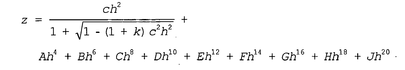
beschreibbar ist, ist der Krümmungsmittelpunkt durch den Mittelpunkt einer Kugel mit dem Krümmungsradius R gegeben. In der Gleichung bezeichnet z die Pfeilhöhe der betreffenden Fläche parallel zur optischen Achse, h den radialen Abstand von der optischen Achse, c = 1/R die Scheitelkrümmung der betreffenden Fläche, k die konische Konstante und A, B, C, D, E, F, G, H und J Asphärenkonstanten. Die Lage einer Symmetrieachse, bezüglich der eine asphärische Fläche rotationssymmetrisch ist und auf welcher der Krümmungsmittelpunkt des sphärischen Anteils liegen kann, aber nicht notwendigerweise liegen muss, lässt sich durch das erfindungsgemäße Verfahren hingegen nicht ermitteln. Auch Planflächen lassen sich mit Hilfe des erfindungsgemäßen Verfahrens vermessen. Die Winkelmesseinrichtung liefert in diesem Fall allerdings keine Positionen von Krümmungsmittelpunkten, sondern die Winkel, welche die Planfläche zur Bezugsachse einschließt.The method according to the invention also makes it possible to measure positions of centers of curvature in aspherical surfaces. The center of curvature in this case is defined only with respect to the spherical portion of the aspherical surface. In an aspheric surface, by the usual aspheric equation
is writable, the center of curvature is given by the center of a sphere with the radius of curvature R. In the equation z denotes the height of the respective surface parallel to the optical axis, h the radial distance from the optical axis, c = 1 / R the vertex curvature of the relevant surface, k the conic constant and A , B , C, D, E, F, G, H and J aspheric constants. The position of a symmetry axis, with respect to which an aspherical surface is rotationally symmetric and on which the center of curvature of the spherical portion can lie, but need not necessarily lie, can not be determined by the method according to the invention. Planar surfaces can also be measured with the aid of the method according to the invention. In this case, however, the angle measuring device does not provide any positions of centers of curvature, but rather the angle which encloses the plane surface relative to the reference axis.
Hinsichtlich der Vorrichtung wird die eingangs genannte Aufgabe gelöst durch eine Vorrichtung zur Messung der Positionen von Krümmungsmittelpunkten optischer Flächen eines mehrlinsigen optischen Systems mit
- a) einem Interferometer, das als Kurzkohärenz-Interferometer ausgebildet und dazu eingerichtet ist, Abstände zwischen den Flächen entlang einer Bezugsachse zu messen,
- b) einer optischen Winkelmesseinrichtung, die dazu eingerichtet ist, die Positionen der Krümmungsmittelpunkte der optischen Flächen zu messen,
- c) einer Recheneinheit, die dazu eingerichtet ist, bei der Messung der Position des Krümmungsmittelpunkts einer innerhalb des optischen Systems liegenden Fläche
- die gemessenen Positionen der Krümmungsmittelpunkte der zwischen dieser Fläche und der Winkelmesseinrichtung liegenden Flächen und
- die von dem Interferometer gemessenen Abstände zwischen den Flächen
- a) an interferometer designed as a short-coherence interferometer and adapted to measure distances between the surfaces along a reference axis,
- b) an optical angle measuring device which is adapted to measure the positions of the centers of curvature of the optical surfaces,
- c) a computing unit adapted to measure the position of the center of curvature of a surface located within the optical system
- the measured positions of the centers of curvature of lying between this surface and the angle measuring surfaces and
- the distances between the surfaces measured by the interferometer
Die vorstehend zum Verfahren genannten Ausgestaltungen und Vorteile gelten hier entsprechend.The above-mentioned embodiments and advantages apply here accordingly.
Die Vorrichtung kann eine Prüflichtquelle aufweisen, die dazu eingerichtet ist, von einer Seite des optischen Systems Prüflicht in dieses einzukoppeln. Ferner kann ein ortsauflösender Lichtsensor vorgesehen sein, der dazu eingerichtet ist, auf der gegenüberliegenden Seite des optischen Systems austretendes Prüflicht ortsaufgelöst zu erfassen. Insbesondere kann die Prüflichtquelle dabei in das Interferometer integriert sein.The device may include a test light source configured to inject test light from one side of the optical system. Furthermore, a spatially resolving light sensor can be provided which is set up to detect spatially resolved test light emerging on the opposite side of the optical system. In particular, the test light source can be integrated into the interferometer.
Außerdem kann die Vorrichtung eine Drehmechanik aufweisen, die dazu eingerichtet ist, das optische System um die Bezugsachse zu drehen.In addition, the apparatus may include a rotating mechanism configured to rotate the optical system about the reference axis.
Das Interferometer und die Winkelmesseinrichtung können auf der gleichen Seite des optischen Systems angeordnet sein. In diesem Fall kann eine Fokussieroptik vorgesehen sein, durch die hindurch sowohl von dem Interferometer erzeugtes Abstands-Messlicht als auch von der Winkelmesseinrichtung erzeugtes Winkel-Messlicht auf das optische System gerichtet wird.The interferometer and the angle measuring device can be arranged on the same side of the optical system. In this case, focusing optics can be provided, through which both the distance measuring light generated by the interferometer and the angle measuring light generated by the angle measuring device are directed onto the optical system.
Weitere Merkmale und Vorteile der Erfindung ergeben sich aus der nachfolgenden Beschreibung der Ausführungsbeispiele anhand der Zeichnungen. Darin zeigen:
Figur 1- einen Meridionalschnitt durch ein mehrlinsiges optisches System, bei dem alle Linsen perfekt zu einer Referenzachse ausgerichtet sind;
- Figur 2
- eine einzelne Linse aus dem in
der Figur 1 gezeigten optischen System, die jedoch gegenüber der Referenzachse verkippt ist; Figur 3- eine schematische Darstellung der Krümmungsmittelpunkte eines mehrlinsigen optischen Systems;
- Figur 4
- eine schematische Darstellung wie in
der Figur 3 , wobei die Krümmungsmittelpunkte jedoch auf einer von der Referenzachse verschiedenen Geraden liegen; - Figur 5
- einen Meridionalschnitt durch eine erfindungsgemäße Messvorrichtung gemäß einem ersten Ausführungsbeispiel;
- Figur 6
- einen Meridionalschnitt durch einen in der Messvorrichtung verwendeten Autokollimator bei der Vermessung einer exakt auf der Bezugsachse ausgerichteten Kugellinse;
- Figur 7
- den Autokollimator aus der
Figur 6 , jedoch mit dezentrierter Kugellinse; - Figur 8
- einen Graphen, in dem die während einer Abstandsmessung von einem Photodetektor erfasste Intensität in Abhängigkeit von der optischen Weglänge aufgetragen ist, die von einem Referenzlichtstrahl eines Interferometers der Messvorrichtung zurückgelegt wird;
- Figur 9
- einen Meridionalschnitt durch eine erfindungsgemäße Messvorrichtung gemäß einem anderen Ausführungsbeispiel, bei dem das Interferometer und der Autokollimator auf der gleichen Seite des Prüflings angeordnet sind;
- Figur 10
- ein Flussdiagramm zur Erläuterung wichtiger Schritte des erfindungsgemäßen Verfahrens.
- FIG. 1
- a meridional section through a multi-lens optical system in which all lenses are perfectly aligned to a reference axis;
- FIG. 2
- a single lens made in the
FIG. 1 shown optical system, however, tilted with respect to the reference axis; - FIG. 3
- a schematic representation of the centers of curvature of a multi-lens optical system;
- FIG. 4
- a schematic representation as in the
FIG. 3 however, the centers of curvature lie on a straight line different from the reference axis; - FIG. 5
- a meridional section through a measuring device according to the invention according to a first embodiment;
- FIG. 6
- a Meridionalschnitt by an autocollimator used in the measuring device in the measurement of a precisely aligned on the reference axis ball lens;
- FIG. 7
- the autocollimator from the
FIG. 6 , but with decentered ball lens; - FIG. 8
- a graph in which the detected by a photodetector during a distance measurement intensity is plotted against the optical path length, which is covered by a reference light beam of an interferometer of the measuring device;
- FIG. 9
- a meridional section through a measuring device according to the invention according to another embodiment, in which the interferometer and the autocollimator are arranged on the same side of the specimen;
- FIG. 10
- a flowchart for explaining important steps of the method according to the invention.
Die
Im Idealfall sind die Linsen L1 bis L7 so ausgerichtet, dass ihre optischen Achsen alle auf einer gemeinsamen Referenzachse 14 liegen, die gleichzeitig die Symmetrieachse der zylindrischen Linsenränder ist. Die Referenzachse 14 wird dann im Allgemeinen als die optische Achse des optischen Systems 10 bezeichnet.Ideally, the lenses L1 to L7 are aligned so that their optical axes are all on a
Bei realen optischen Systemen kommt es jedoch aufgrund von Fertigungs- und Montagetoleranzen zu Abweichungen von einer solchen idealen Ausrichtung. Die
Bei asphärischen Linsen ist die optische Achse durch die Krümmungsmittelpunkte des sphärischen Anteils der asphärischen Linsenflächen definiert.For aspheric lenses, the optical axis is defined by the centers of curvature of the spherical portion of the aspherical lens surfaces.
Die Verkippung der Linse L5 kann beispielsweise dadurch hervorgerufen sein, dass die Linse L5 nicht korrekt in ihre Linsenfassung eingesetzt wurde. Als Ursache hierfür kommt etwa in Betracht, dass der Linsenrand 12 nicht so geschliffen wurde, dass seine Symmetrieachse mit der optischen Achse 16 der Linse L5 fluchtet.The tilting of the lens L5 may be caused, for example, by the lens L5 not being properly inserted in its lens barrel. The reason for this is considered, for example, that the
Um die Linse L5 korrekt auf der Referenzachse 14 des optischen Systems 10 auszurichten, müsste die Linse L5 so verkippt und ggf. zusätzlich senkrecht zur Referenzachse 14 verschoben werden, dass die optische Achse 16 mit der Referenzachse 14 fluchtet, wie dies in der
Bei einem mehrlinsigen optischen System, wie es in der
Dies ist beispielhaft in der
Gelegentlich kann es auch, wie die
Um ggf. einzelne Linsen eines optischen Systems oder das optische System insgesamt nachjustieren zu können, aber auch zur regelmäßigen Qualitätssicherung wird eine erfindungsgemä-βe Messvorrichtung eingesetzt, mit der sich die Positionen der Krümmungsmittelpunkte der optischen Flächen mit hoher Genauigkeit messen lassen. Aus den Positionen der Krümmungsmittelpunkte lassen sich die Lagen der optischen Achsen der Einzellinsen und deren Abweichung von einer Referenzachse 14 bestimmen. Ferner ist es möglich, daraus abgeleitete Größen zu bestimmen, etwa die Krümmungsradien der optischen Flächen. Im folgenden Abschnitt 2. wird zunächst der Aufbau der erfindungsgemäßen Messvorrichtung mit Bezug auf die
Die in der
Der Autokollimator 22 enthält eine Lichtquelle 38, die eine Lochblende 40 mit Winkel-Messlicht ausleuchtet. Das aus der Lochblende 40 austretende Winkel-Messlicht wird über einen Strahlteiler 42 auf eine Kollimatorlinse 44 gerichtet und verlässt diese als achsparalleles Strahlenbündel. Eine entlang der Bezugsachse 34 verfahrbare Zoomlinse 46 bündelt das achsparallele Winkel-Messlicht in einem Brennpunkt 48. Im Brennpunkt 48 entsteht somit ein Bild der Lochblende 40. Wird anstelle der Lochblende 40 eine Blende mit einer anders geformten Öffnung, z. B. einer Kreuzschlitzöffnung, gewählt, so entsteht in der Brennebene der Zoomlinse 46 ein Bild des Kreuzschlitzes.The
Auf der rückwärtigen Seite des Strahlteilers 42 ist ein Bildsensor 50 angeordnet, worunter hier ein lichtempfindlicher ortsauflösender Sensor verstanden wird. Geeignet als Bildsensor sind beispielsweise an sich bekannte CCD- oder CMOS-Sensoren.On the rear side of the
Die Funktion des Autokollimators 22 wird im Folgenden mit Bezug auf die
Die
Wird die Kugel 52 nun auf dem Drehtisch 30 um die Bezugsachse 34 gedreht, so beschreibt das Bild 60 auf dem Bildsensor 50 eine Kreisbahn. Aus der Lage des Mittelpunkts dieser Kreisbahn relativ zur Bezugsachse lässt sich ermitteln, wo der Mittelpunkt 54 der Kugel 52 relativ zur Bezugsachse 34 liegt.If the
Da die Dezentrierung der Kugel 52 letztlich eine Verkippung des dem Autokollimator 22 zugewandten Teils der Oberfläche 56 bedeutet, misst der Autokollimator 22 letztlich den Winkel, den die Oberfläche 56 der Kugel 52 zur Bezugsachse 34 einschließt. Der Autokollimator stellt deswegen im weiteren Sinne eine Winkelmesseinrichtung dar. Dementsprechend können auch andere berührungslos arbeitende Winkelmesseinrichtungen anstelle des Autokollimators 22 eingesetzt werden.Since the decentering of the
Bei Linsen mit sphärischen Flächen funktioniert dieser Messvorgang in gleicher Weise, nur dass die Messung nicht wie bei einer Kugel die Position eines Kugelmittelpunkts, sondern die Position des Krümmungsmittelpunkts der betreffenden sphärischen Fläche ergibt.In the case of lenses with spherical surfaces, this measuring process works in the same way, except that the measurement does not give the position of a spherical center, as in the case of a sphere, but the position of the center of curvature of the relevant spherical surface.
Im Folgenden wird wieder Bezug auf die
Im Folgenden wird der Aufbau des Interferometers 24 näher erläutert. Das Interferometer 24 ist als Kurzkohärenz-Interferometer ausgebildet und enthält zu diesem Zweck eine im Vergleich zu einer Laserlichtquelle spektral breitbandige Lichtquelle 64, bei der es sich z. B. um eine Superlumineszenzdiode handeln kann. Infolge der vergleichsweise großen spektralen Bandbreite hat das von der Lichtquelle 64 erzeugte Licht eine wesentliche kürzere Kohärenzlänge als Licht, das von Laserlichtquellen erzeugt wird. Alternativ kann eine Laserlichtquelle verwendet werden, die extrem kurze Lichtpulse erzeugt, da auch solche Lichtpulse eine sehr kurze Kohärenzlänge haben.The structure of the
Von der Lichtquelle 64 erzeugtes Abstands-Messlicht wird von einer Sammellinse 66 gebündelt und auf einen Strahlteilerwürfel 68 gerichtet, der das Abstands-Messlicht in einen auf den Prüfling 62 gerichteten Messlichtstrahl 70 und einen Referenzlichtstrahl 72 aufteilt. Der Referenzlichtstrahl 72 wird von einem Spiegel 74 in sich reflektiert, der mit Hilfe eines Aktuators 76 entlang der Strahlrichtung verfahrbar ist. Auf diese Weise lässt sich die optische Weglänge des Referenzlichtstrahls 72 zwischen dem Strahlteilerwürfel 68 und dem Spiegel 74 verändern.Distance measuring light generated by the
Der Messlichtstrahl 70 wird über eine Optik 78 auf den Prüfling 62 gerichtet. Das an den optischen Flächen S1, S2 und S3 reflektierte Messlicht 80 gelangt zurück über die Optik 78 auf den Strahlteilerwürfel 68 und wird von diesem teilweise in Richtung eines Photodetektors 82 reflektiert. Dort überlagert sich das reflektierte Messlicht 80 mit dem vom Spiegel 74 reflektierten Referenzlichtstrahl 72.The measuring
Liegt die Differenz der optischen Weglängen, die der Messlichtstrahl 70 und der Referenzlichtstrahl 72 bis zu ihrem Weg auf den Photodetektor 82 zurückgelegt haben, in der Grö-βenordnung der Kohärenzlänge des von der Lichtquelle 64 erzeugten Abstands-Messlicht, so kommt es zu Interferenzerscheinungen, die vom Photodetektor 82 erfasst werden. Da die Kohärenzlänge des von der Lichtquelle 64 erzeugten Abstands-Messlichts kurz ist, erzeugt der Photodetektor 82 weglängenmäßig scharf begrenzte Ausgangssignale, wenn die vorstehend genannte Bedingung erfüllt ist.If the difference of the optical path lengths which the
Die
Aus den Positionen der Maxima der Hüllkurven 83 der Messsignale lassen sich unter Berücksichtigung des Gruppenbrechungsindex die Abstände zwischen den Flächen S1, S2 und S3 mit sehr hoher Genauigkeit bestimmen.From the positions of the maxima of the
Bei realen Messsignalen liegen zwischen den Hüllkurven 83 im Allgemeinen weitere Interferenzsignale, die z. B. von Mehrfachreflexen innerhalb des Prüflings 62 verursacht sind und teilweise relativ hohe Pegel erreichen können. Damit solche Störsignale die Messung nicht beeinträchtigen, können mit Hilfe von Diskriminatorfenstern, die um die Hüllkurven 83 gelegt werden, die Störsignale ausgeblendet werden. Die Diskriminatorfenster werden vorzugsweise automatisch dort positioniert, wo Interferenzsignale unter Zugrundelegung der Soll-Abstände zwischen den Flächen S1, S2, S3 zu erwarten sind. Damit möglichst viel Messlicht von den Flächen S1, S2, S3 des Prüflings 62 reflektiert und dem Photodetektor 82 zugeleitet werden kann, kann der Messlichtstrahl 70 mit Hilfe der Optik 78 an den Prüfling 62 angepasst werden.In real measurement signals between the
Weitere Einzelheiten zur Vermessung von Dicken transparenter Körper mit Hilfe eines Kurzkohärenz-Interferometers können der
Die
Zu diesem Zweck weist die Messvorrichtung 20 einen zweiten Strahlteilerwürfel 90 auf, der das vom ersten Strahlteilerwürfel 68 reflektierte Licht in den Messlichtstrahl 70 und den Referenzstrahl 72 aufteilt. Der erste Strahlteilerwürfel 68 hat bei diesem Ausführungsbeispiel lediglich die Aufgabe, das von der Lichtquelle 64 erzeugte Licht in denjenigen Arm des Interferometers 24 einzukoppeln, der den Photodetektor 82 enthält. Die Zoomlinse 46 dient bei diesem Ausführungsbeispiel sowohl der Fokussierung des Winkel-Messlichts als auch des Abstands-Messlichts 70.For this purpose, the measuring
Ansonsten sind die in den
Im Folgenden wird das erfindungsgemäße Messverfahren mit Bezug auf das in der
Vorausgesetzt wird zunächst, dass die optische Achse des Autokollimators 22, die Drehachse des Drehtischs 30 und der Messlichtstrahl 70 des Interferometers 24 so zueinander ausgerichtet sind, dass sie auf der gemeinsamen Bezugsachse 34 liegen. Eine solche Justierung erfolgt nur einmalig vor der erstmaligen Inbetriebnahme der Messvorrichtung 20.It is first assumed that the optical axis of the
Um zunächst eine Parallelität der Drehachse des Drehtischs 30 mit der optischen Achse des Autokollimators 22 zu erzielen, kann über die Öffnung des Drehtischs 30 ein Planspiegel gelegt werden. Der Autokollimator 22 und der Drehtisch 30 werden dann so lange zueinander justiert, bis das Bild der Lochblende 40 auf dem Bildsensor 50 exakt zur optischen Achse des Autokollimators 22 zentriert ist.In order initially to achieve a parallelism of the axis of rotation of the
In einem zweiten Schritt wird in die Öffnung des ringförmigen Drehtisches 30 eine Kugellinse eingesetzt, um eine exakt koaxiale Ausrichtung der optischen Achse des Autokollimators 22 und der Drehachse des Drehtisches 30 zu erzielen. Der Autokollimator 22 und der Drehtisch 30 werden dann so lange zueinander justiert, bis das Bild der Lochblende 40 auf dem Bildsensor 50 wieder zur optischen Achse des Autokollimators zentriert ist.In a second step, a ball lens is inserted into the opening of the
In gleichartiger Weise kann auch das Interferometer 24 relativ zum Drehtisch 30 ausgerichtet werden. Eine optimale Ausrichtung auf die gemeinsame Bezugsachse 34 ist dann erreicht, wenn bei Einsetzen eines Planspiegels und einer Kugellinse die vom Photodetektor 82 erfasste Intensität jeweils maximal ist.Similarly, the
Zur Messung der Positionen der Krümmungsmittelpunkte des mehrlinsigen Prüflings 62 werden zunächst in einem Schritt ST1 die Abstände zwischen den Flächen S1, S2, S3 mit Hilfe des Interferometers 24 gemessen. Um reproduzierbare und genaue Messergebnisse zu erhalten, muss dabei jedoch der Messlichtstrahl 70 des Interferometers 24 sehr genau zur optischen Achse des Prüflings 62 ausgerichtet sein. Denn nur wenn der Messlichtstrahl 40 senkrecht auf die optischen Flächen S1, S2, S3 fällt, gelangt genügend von den Flächen S1, S2, S3 reflektiertes Messlicht zurück auf den Photodetektor 82 und kann dort zur Interferenz mit dem Referenzlichtstrahl 72 beitragen. Dies wiederum ist gleichbedeutend mit der Forderung, dass die Krümmungsmittelpunkte K1, K2, K3 auf der Bezugsachse 34 liegen.In order to measure the positions of the centers of curvature of the
Im Allgemeinen ist diese Voraussetzung jedoch nicht gegeben, weil der Prüfling 62 zunächst verkippt und/oder dezentriert auf dem Drehtisch 30 gehalten ist, wie dies in der
Allerdings ist die optische Achse des Prüflings 62 zunächst überhaupt nicht bekannt. Es ist deswegen erforderlich, vor der Ausrichtung des Prüflings 62 relativ zum Interferometer 24 die optische Achse des Prüflings 62 vorläufig zu bestimmen. Hierzu kommen mehrere Möglichkeiten in Betracht.However, the optical axis of the
Eine Möglichkeit besteht darin, bereits vor der Messung der Abstände die Positionen der Krümmungsmittelpunkte der Flächen S1, S2, S3 vorläufig zu bestimmen und daraus eine optische Achse des Prüflings 62 abzuleiten. Wie man mit Hilfe des Autokollimators 22 die Positionen der Krümmungsmittelpunkte misst, wird weiter unten im Abschnitt 3.c) näher erläutert.One possibility is to provisionally determine the positions of the centers of curvature of the surfaces S1, S2, S3 and to derive therefrom an optical axis of the
Die Ableitung einer optischen Achse des Prüflings 62 aus vorläufig bestimmten Krümmungsmittelpunkten K1, K2, K3 kann auf verschiedene Weise erfolgen. So kann beispielsweise durch die Krümmungsmittelpunkte K1, K2, K3 eine Ausgleichsgerade gelegt werden, die als optische Achse des Prüflings 62 definiert wird. Bei der Festlegung der Ausgleichsgeraden kann auch eine Gewichtung der Krümmungsmittelpunkte K1, K2, K3 vorgenommen werden, die sich beispielsweise an den Krümmungsradien der betreffenden Flächen orientiert. In der
Da die Bestimmung der optischen Achse 92 lediglich vorläufig ist und keine höchste Genauigkeit erfordert, kann die optische Achse 92 auch auf einfachere Weise festgelegt werden. So können beispielsweise nur die Krümmungsmittelpunkte K1 und K3 der ersten Fläche S1 bzw. der letzten Fläche S3 in der Weise berücksichtigt werden, dass die vorläufige optische Achse durch diese Krümmungsmittelpunkte hindurch verläuft.Since the determination of the
Eine andere Möglichkeit, die optische Achse 92 des Prüflings 62 vorläufig zu bestimmen, besteht darin, den Prüfling 62 in Transmission zu durchleuchten. Hierzu wird die Weißlichtquelle 64 des Interferometers 24 genutzt, um einen Prüflichtstrahl auf den Prüfling 62 zu richten. Der Prüflichtstrahl durchtritt den Prüfling 62 sowie die Zoomlinse 46, die Kollimatorlinse 44 und den Strahlteiler 42 und erzeugt auf dem Bildsensor 50 einen Lichtfleck. Liegen die Krümmungsmittelpunkte K1, K2, K3 auf der Bezugsachse 34, dann durchtritt der Prüflichtstrahl die optischen Flächen S1, S2, S3 senkrecht und breitet sich folglich geradlinig entlang der Bezugsachse 34 aus.Another way to provisionally determine the
Im Allgemeinen jedoch liegen die Krümmungsmittelpunkte K1, K2, K3 nicht exakt auf der Bezugsachse 34. Dann trifft der Prüflichtstrahl nicht senkrecht, sondern schräg auf die Flächen S1, S2, S3 auf, so dass er beim Durchtritt durch den Prüfling 62 infolge Brechung an den Flächen S1, S2, S3 abgelenkt wird. Infolge dieser Ablenkung verlagert sich auch der Lichtfleck auf dem Bildsensor 50 von der Bezugsachse 34 weg.In general, however, the centers of curvature K1, K2, K3 are not exactly on the
Wird nun während einer solchen Durchleuchtung des Prüflings 62 mit Prüflicht der Prüfling 62 mit Hilfe des Drehtischs 30 um die Bezugsachse 34 gedreht, so wandert auch der Lichtfleck auf dem Bildsensor 50 um die Bezugsachse 34 herum. Aus der Bahn dieses Lichtflecks kann man allerdings nicht quantitativ auf die Positionen der Krümmungsmittelpunkte K1, K2, K3 schließen. Wird die Prüflingsaufnahme 28 mit dem darin aufgenommenen Prüfling 62 jedoch so lange verkippt und/oder verschoben, bis die Kreisbahn des Lichtflecks auf dem Bildsensor 50 einen minimalen Durchmesser hat, so ist auch der Abstand der Krümmungsmittelpunkte K1, K2, K3 von der Bezugsachse 34 minimal. Die optische Achse des Prüflings 62 ist dann in der gewünschten Weise gut zur Bezugsachse 34 der Messvorrichtung 20 ausgerichtet.If the
Eine weitere Möglichkeit zur Justierung des Prüflings 28 auf dem Drehtisch 30 besteht darin, ähnlich wie bei der Variante i) mit Hilfe des Autokollimators 22 die Positionen der Krümmungsmittelpunkte K1, K2, K3 der Flächen S1, S2, S3 des Prüflings 62 vorläufig zu bestimmen. Im Wege einer Simulation, z. B. durch Ray-Tracing-Verfahren, wird dann ermittelt, welche Intensitäten am Photodetektor 82 zu erfassen wären, wenn der Prüfling 62 mit den vorab gemessenen Krümmungsmittelpunkten K1, K2, K3 optimal auf den Drehtisch 92 ausgerichtet wäre. Eine solche optimale Ausrichtung kann dadurch definiert sein, dass die Krümmungsmittelpunkte K1, K2, K3 sich dann im Mittel möglichst nahe der Bezugsachse 34 befinden; ggf. kann hier auch ein abgewandeltes Kriterium verwendet werden. Die Verkippung und/oder Verschiebung des Prüflings 62 auf dem Drehtisch 30 wird dann so lange durchgeführt, bis vom Photodetektor 82 die vorab berechneten Intensitäten erfasst werden.A further possibility for adjusting the
Nachdem also der Prüfling 62 nach einer der drei vorstehend erläuterten Varianten i) bis iii) optimal zur Bezugsachse 34 der Messvorrichtung 20 ausgerichtet wurde, werden die Abstände zwischen den Flächen S1, S2, S3 mit Hilfe des Interferometers 24 gemessen. Hierzu wird in der oben bereits beschriebenen Weise die optische Weglänge des Referenzlichtstrahls 72 durch Verfahren des Spiegels 74 durchgestimmt und das Interferenzsignal des Photodetektors 82 erfasst und ausgewertet.Thus, after the
In einem zweiten Schritt ST2 werden die Positionen der Krümmungsmittelpunkte K1, K2, K3 der Flächen S1, S2, S3 mit Hilfe des Autokollimators 22 vermessen. Hierbei wird wie folgt vorgegangen:In a second step ST2, the positions of the centers of curvature K1, K2, K3 of the surfaces S1, S2, S3 are measured with the aid of the
Um bei einem mehrlinsigen Prüfling 62 die Positionen der Krümmungsmittelpunkte K1, K2 und K3 der optischen Flächen S1, S2, S3 zu messen, müssen mehrere Messvorgänge nacheinander durchgeführt werden. Begonnen wird dabei z. B. mit derjenigen optischen Fläche, die dem Autokollimator 22 am nächsten liegt. Bei dem Prüfling 62 ist dies die Fläche S1.In order to measure the positions of the centers of curvature K1, K2 and K3 of the optical surfaces S1, S2, S3 in the case of a
Zur Bestimmung der Position des Krümmungsmittelspunkts der Fläche S1 wird die Zoomlinse 46 des Autokollimators 22 so verfahren, dass der Brennpunkt 48 des Winkel-Messlichts in der Nähe des auf der Grundlage der Designdaten erwarteten Krümmungsmittelpunkts liegt. Dann wird der Drehtisch 30 in Rotation gesetzt und die Wanderung des Bildes der Lochblende 40 auf dem Bildsensor 50 aufgezeichnet. Wie oben bereits mit Bezug auf die
Nachdem die Position des Krümmungsmittelpunkts K1 der ersten Fläche S1ermittelt wurde, wird die Zoomlinse 46 so verfahren, dass der Brennpunkt 48 des Winkel-Messlichts zumindest annähernd im Krümmungsmittelpunkt K2 der in Lichtausbreitungsrichtung folgenden Fläche S2 zu liegen kommt. Da das vom Autokollimator 22 ausgehende Winkel-Messlicht nun aber zusätzlich auch die zuvor bereits vermessene Fläche S1 durchtritt, müssen die bei der zweiten Messung erhaltenen Messwerte rechnerisch um die optische Wirkung der ersten Fläche S1 korrigiert werden. Rechnerisch berücksichtigt werden dabei in einem Schritt ST3 die Position des Krümmungsmittelpunkts K1 der bereits vermessenen Fläche S1 und in einem Schritt ST4 der bereits mit Hilfe des Interferometers 24 gemessene Abstand zwischen den beiden Flächen S1 und S2 entlang der Bezugsachse 34, wobei die Schritte ST3 und ST4 im Allgemeinen Teil einer gemeinsamen Korrekturrechnung am Ende des gesamten Messvorgangs sein werden.After the position of the center of curvature K1 of the first surface S1 has been determined, the
Bei der Bestimmung der optischen Wirkung der ersten Fläche S1 wird in der Regel der Krümmungsradius dieser Fläche benötigt. Bei sphärischen Linsen können die Krümmungsradien aus den Positionen der Krümmungsmittelpunkte K1, K2, K3 und den Abständen der Flächen S1, S2, S3 unmittelbar abgeleitet werden. Alternativ können die Krümmungsradien auch den Design-Daten der Fläche S1 entnommen oder in einem zusätzlichen Messvorgang mit Hilfe des Autokollimators 22 gemessen werden. Der Krümmungsradius ist nämlich bei einer sphärischen Linse gleich dem Abstand zwischen dem Krümmungsmittelpunkt K1 und einem beliebigen Punkt auf der optischen Fläche S1. Die Position eines solchen Punkts kann einfach dadurch gemessen werden, indem der Brennpunkt 48 der Zoomlinse 46 auf die optische Fläche S1 gelegt wird. Das auf dem Bildsensor 50 entstehende Bild der Lochblende 40 hat dann seine maximale Intensität.In determining the optical effect of the first surface S1, the radius of curvature of this surface is generally required. For spherical lenses, the radii of curvature can be derived directly from the positions of the centers of curvature K1, K2, K3 and the distances of the surfaces S1, S2, S3. Alternatively, the radii of curvature can also be taken from the design data of the area S1 or measured in an additional measuring operation with the aid of the
Hervorzuheben ist, dass für den ebenfalls zu berücksichtigenden Abstand zwischen der ersten Fläche S1 und der zweiten Fläche S2 entlang der Bezugsachse 34 nicht wie im Stand der Technik auf Designdaten, sondern auf den zuvor mit Hilfe des Interferometers 24 ermittelten Messwert für diesen Abstand zurückgegriffen wird.It should be emphasized that the distance between the first surface S1 and the second surface S2 along the
Bei allen weiteren optischen Flächen des Prüflings 62 erfolgt die Messung der Positionen der Krümmungsmittelpunkte in gleicher Weise. Es werden dabei stets die Positionen der Krümmungsmittelpunkte aller vorausliegenden Flächen und die von dem Interferometer gemessenen Abstände zwischen den vorausliegenden Flächen gemäß den Schritten ST3 und ST4 rechnerisch berücksichtigt. Auf diese Weise erhält man eine räumliche Anordnung aller Krümmungsmittelpunkte K1, K2 und K3.In all other optical surfaces of the
Falls eine Vermessung der Positionen der Krümmungsmittelpunkte K1, K2, K3 bereits zuvor durchgeführt wurde, um die optische Achse 92 des Prüflings 62 vorläufig bestimmen und den Prüfling 62 zum Zwecke der Abstandsmessung an der Bezugsachse 34 ausrichten zu können, kann diese Messung im Schritt ST2 wiederholt werden, da unter Umständen mit dem nun besser ausgerichteten Prüfling 62 eine höhere Genauigkeit bei der Messung der Positionen der Krümmungsmittelpunkte K1, K2, K3 erreicht wird. Es ist aber alternativ hierzu ebenfalls möglich, die bereits erhaltenen Messergebnisse, d. h. die auf dem Bildsensor 50 für die einzelnen Flächen S1, S2, S3 erhaltenen Lichtmuster, zu verwenden und die zuvor im Schritt ST1 genau vermessenen Abstände zwischen den Flächen S1, S2, S3 lediglich bei der rechnerischen Auswertung zu berücksichtigen. Die Schritte ST1 und ST2 werden dann in umgekehrter Reihenfolge durchgeführt.If a measurement of the positions of the centers of curvature K1, K2, K3 has already been performed beforehand to provisionally determine the
Ferner kann es zweckmäßig sein, die Messung der Positionen der Krümmungsmittelpunkte K1, K2, K3 nicht wie vorstehend beschrieben in der Reihenfolge der optischen Flächen S1, S2, S3, sondern in der Reihenfolge deren Soll-Krümmungsmittelpunkte durchzuführen. Bei dem in der
Das Ergebnis der Messung ist eine sehr präzise Bestimmung der Krümmungsmittelpunkte des Prüflings 62, die auch nicht durch Abweichungen der tatsächlichen Abstände zwischen den optischen Flächen S1, S2, S3 von den Designdaten verfälscht wird. Aus den exakt ermittelten Krümmungsmittelpunkten und den gemessenen Abständen kann der Computer 26 auch die Krümmungsradien exakt bestimmen. Sehr genau gemessene Luftabstände und Mittendicken der Linsen des Prüflings 62 fallen zusätzlich als nützliche Messergebnisse an. Man erhält somit ausgehend von einem Designdatensatz, der u. a. Sollwerte für die Positionen der Krümmungsmittelpunkte, die Luftabstände zwischen den Linsen und die Mittendicken der Linsen enthält, einen korrigierten Ist-Datensatz, in dem die genannten Soll-Werte durch hochgenaue Messwerte ersetzt sind.The result of the measurement is a very precise determination of the centers of curvature of the
Claims (15)
rechnerisch berücksichtigt werden (ST3, ST4).
calculated (ST3, ST4).
rechnerisch zu berücksichtigen.
calculated.
Applications Claiming Priority (1)
| Application Number | Priority Date | Filing Date | Title |
|---|---|---|---|
| DE201010053422 DE102010053422B3 (en) | 2010-11-29 | 2010-11-29 | Measurement of the positions of centers of curvature of optical surfaces of a multi-lens optical system |
Publications (2)
| Publication Number | Publication Date |
|---|---|
| EP2458363A1 true EP2458363A1 (en) | 2012-05-30 |
| EP2458363B1 EP2458363B1 (en) | 2015-11-11 |
Family
ID=45023513
Family Applications (1)
| Application Number | Title | Priority Date | Filing Date |
|---|---|---|---|
| EP11009187.3A Active EP2458363B1 (en) | 2010-11-29 | 2011-11-19 | Measurement of the positions of curvature midpoints of optical areas of a multi-lens optical system |
Country Status (4)
| Country | Link |
|---|---|
| US (1) | US8913234B2 (en) |
| EP (1) | EP2458363B1 (en) |
| JP (1) | JP5902448B2 (en) |
| DE (1) | DE102010053422B3 (en) |
Cited By (1)
| Publication number | Priority date | Publication date | Assignee | Title |
|---|---|---|---|---|
| WO2014114444A1 (en) * | 2013-01-23 | 2014-07-31 | Jenoptik Optical Systems Gmbh | System for determining the position of a test object and associated method |
Families Citing this family (14)
| Publication number | Priority date | Publication date | Assignee | Title |
|---|---|---|---|---|
| DE102013004738A1 (en) | 2013-03-12 | 2014-10-02 | Fraunhofer-Gesellschaft zur Förderung der angewandten Forschung e.V. | Method for the targeted adjustment of optical components to a reference axis |
| CN103940377B (en) * | 2014-03-26 | 2017-01-04 | 中国科学院长春光学精密机械与物理研究所 | Optical lens centre of sphere deviation measurement device |
| EP3037800B1 (en) * | 2014-12-24 | 2018-04-04 | Trioptics GmbH | Measurement of the positions of curvature midpoints of optical areas of a single or multi-lens optical system |
| CN105403151B (en) * | 2015-12-11 | 2018-06-19 | 杭州志达光电有限公司 | Interference and the aspherical eccentricity detecting instrument of projection integration and its detection method |
| DE102016014834B3 (en) * | 2016-12-14 | 2018-04-19 | Innolite Gmbh | Method for ultra-precise centering of a transmissive or reflective optic, in particular a lens with an aspherical or free-form front lens surface |
| CN108801178B (en) * | 2017-05-04 | 2020-07-10 | 北京理工大学 | Differential confocal auto-collimation center deviation and curvature radius measuring method and device |
| DE102018112436A1 (en) * | 2018-05-24 | 2019-11-28 | Carl Zeiss Jena Gmbh | Methods and apparatus for determining alignment errors of beam sources and for their correction |
| JP7404005B2 (en) | 2019-09-10 | 2023-12-25 | オリンパス株式会社 | Eccentricity measuring device and eccentricity measuring method |
| DE102019133738A1 (en) * | 2019-12-10 | 2021-06-10 | AIXEMTEC GmbH | Device, method and use of the device for adjusting, assembling and / or testing an electro-optical system |
| DE102020107298A1 (en) | 2020-03-17 | 2021-09-23 | Berliner Glas GmbH | Method and adjustment device for aligning optical lenses |
| US11460713B2 (en) * | 2020-05-13 | 2022-10-04 | Asm Technology Singapore Pte Ltd | System and method for aligning multiple lens elements |
| CN112697054A (en) * | 2020-12-10 | 2021-04-23 | 无锡鑫巨宏智能科技有限公司 | Microlens rise measuring device and method |
| FR3131955A1 (en) * | 2022-01-17 | 2023-07-21 | Fogale Nanotech | Method and device for determining geometric information of interfaces of an optical element |
| JP2024040947A (en) * | 2022-09-13 | 2024-03-26 | キヤノン株式会社 | Acquisition device, acquisition method, and optical system manufacturing method |
Citations (5)
| Publication number | Priority date | Publication date | Assignee | Title |
|---|---|---|---|---|
| FR2803027A1 (en) | 1999-12-23 | 2001-06-29 | Nanotec Solution | Optical measurement technique for determination of the wall thickness of a transparent container uses two light beams derived from an interferometer to determine the optical path lengths to a target and a reference reflector |
| DE102004029735A1 (en) | 2004-06-21 | 2006-01-12 | Trioptics Gmbh | Optical surfaces measuring method for multi lens assembly, involves calculating adjusting error for optical surface with basic significance of illustrating properties of preliminary lenses that occurs by radiating light and reflected light |
| DE102005013571A1 (en) | 2005-03-23 | 2006-06-14 | Carl Zeiss Smt Ag | Production of an optical lens with an aspheric surface, e.g. for an astronomical telescope, rotates the substrate on a table for measurement at rotary positions of the reference and symmetry axes in relation to the table axis |
| US7133225B1 (en) | 2004-10-18 | 2006-11-07 | Carl Zeiss Smt Ag | Method of manufacturing an optical system |
| US7643149B2 (en) | 2005-05-24 | 2010-01-05 | Carl Zeiss Smt Ag | Method of aligning an optical system |
Family Cites Families (6)
| Publication number | Priority date | Publication date | Assignee | Title |
|---|---|---|---|---|
| JPS61118639A (en) * | 1984-11-15 | 1986-06-05 | Olympus Optical Co Ltd | Apparatus for measuring quantity of eccentricity |
| US7046351B2 (en) * | 2002-05-20 | 2006-05-16 | Pentax Corporation | Method and apparatus for measuring eccentricity of optical lens, and method and apparatus for centering and edging optical lens |
| JP2004069594A (en) * | 2002-08-08 | 2004-03-04 | Olympus Corp | Apparatus and method for measuring amount of eccentricity |
| JP2005147703A (en) * | 2003-11-11 | 2005-06-09 | Olympus Corp | Device and method for measuring surface distance |
| JP4880513B2 (en) * | 2007-03-29 | 2012-02-22 | 富士フイルム株式会社 | Method and apparatus for measuring surface deviation of aspherical lens |
| DE102010053423A1 (en) * | 2010-11-29 | 2012-05-31 | Trioptics Gmbh | Method and device for measuring distances between optical surfaces of an optical system |
-
2010
- 2010-11-29 DE DE201010053422 patent/DE102010053422B3/en active Active
-
2011
- 2011-11-19 EP EP11009187.3A patent/EP2458363B1/en active Active
- 2011-11-22 US US13/302,697 patent/US8913234B2/en active Active
- 2011-11-25 JP JP2011257768A patent/JP5902448B2/en active Active
Patent Citations (5)
| Publication number | Priority date | Publication date | Assignee | Title |
|---|---|---|---|---|
| FR2803027A1 (en) | 1999-12-23 | 2001-06-29 | Nanotec Solution | Optical measurement technique for determination of the wall thickness of a transparent container uses two light beams derived from an interferometer to determine the optical path lengths to a target and a reference reflector |
| DE102004029735A1 (en) | 2004-06-21 | 2006-01-12 | Trioptics Gmbh | Optical surfaces measuring method for multi lens assembly, involves calculating adjusting error for optical surface with basic significance of illustrating properties of preliminary lenses that occurs by radiating light and reflected light |
| US7133225B1 (en) | 2004-10-18 | 2006-11-07 | Carl Zeiss Smt Ag | Method of manufacturing an optical system |
| DE102005013571A1 (en) | 2005-03-23 | 2006-06-14 | Carl Zeiss Smt Ag | Production of an optical lens with an aspheric surface, e.g. for an astronomical telescope, rotates the substrate on a table for measurement at rotary positions of the reference and symmetry axes in relation to the table axis |
| US7643149B2 (en) | 2005-05-24 | 2010-01-05 | Carl Zeiss Smt Ag | Method of aligning an optical system |
Non-Patent Citations (1)
| Title |
|---|
| ALLAIN COURTEVILLE ET AL: "Non-contact in-process metrology using a high-accuracy low-coherence interferometer", 31 May 2006 (2006-05-31), pages 1 - 11, XP055021154, Retrieved from the Internet <URL:http://www.fogale.fr/~fogaleco/media/articles_LISE/LAMDAMAP_2005.pdf> [retrieved on 20120307] * |
Cited By (2)
| Publication number | Priority date | Publication date | Assignee | Title |
|---|---|---|---|---|
| WO2014114444A1 (en) * | 2013-01-23 | 2014-07-31 | Jenoptik Optical Systems Gmbh | System for determining the position of a test object and associated method |
| US10175141B2 (en) | 2013-01-23 | 2019-01-08 | Trioptics Gmbh | System for determining the position of a test object |
Also Published As
| Publication number | Publication date |
|---|---|
| EP2458363B1 (en) | 2015-11-11 |
| JP5902448B2 (en) | 2016-04-13 |
| JP2012118066A (en) | 2012-06-21 |
| US20120133924A1 (en) | 2012-05-31 |
| DE102010053422B3 (en) | 2012-03-29 |
| US8913234B2 (en) | 2014-12-16 |
Similar Documents
| Publication | Publication Date | Title |
|---|---|---|
| EP2458363B1 (en) | Measurement of the positions of curvature midpoints of optical areas of a multi-lens optical system | |
| EP2458321B1 (en) | Method and device for measuring distances between optical areas of an optical system | |
| EP3037800B1 (en) | Measurement of the positions of curvature midpoints of optical areas of a single or multi-lens optical system | |
| EP0370229B1 (en) | Interferometric process for testing optical elements producing aspherical wave fronts | |
| DE102012022487A1 (en) | Apparatus and method for determining the position of two coupled waves to each other | |
| DE102013216566A1 (en) | DEVICE AND METHOD FOR DETECTING AN AT LEAST PARTIAL MIRRORING SURFACE | |
| EP2263062B1 (en) | Device and method for measuring the topography of surfaces of articles | |
| DE102017131224A1 (en) | Method and device for detecting a focal position of a laser beam | |
| DE60312406T2 (en) | Apparatus and method for measuring optical properties of a diffractive optical element | |
| DE102011012611B4 (en) | Method and device for non-contact measurement of an angle | |
| WO1986004676A2 (en) | Device for optical determination of low-order errors in shape | |
| DE102010004824A1 (en) | Device for determining e.g. refraction index of V or wedge shaped samples, has adjusting device adjusting rotational angle of deflecting mirror, and measuring telescope firmly arranged opposite to beam directed towards prism | |
| EP1918687A1 (en) | Method and device for determining the position of the symmetrical axis of an aspherical lens surface | |
| DE102018222231A1 (en) | Device and method for the optical measurement of an inner contour of a spectacle frame | |
| DE102019105627B3 (en) | Collimator and method for testing a camera | |
| DE102006015627A1 (en) | Rotation symmetric part`s form deviation and ripple determining method, involves conducting high pass filtering of measurement curve of reflection signal, where curve shows form deviation of testing part | |
| EP0600048A1 (en) | Process for measuring relative angles | |
| DE102014001151A1 (en) | Measurement of the positions of centers of curvature of optical surfaces of a multi-lens optical system | |
| WO2005022127A2 (en) | Device for measuring a planar element | |
| AT510097B1 (en) | METHOD FOR MEASURING THE ORIENTATION OF A SHAFT WITH RESPECT TO A REFERENCE SURFACE | |
| DE102006032404B4 (en) | Apparatus and method for determining surface properties | |
| DE202013003898U1 (en) | Goniometer for optical prisms | |
| DE3233101A1 (en) | Method for determining the angle of the normals of a specimen rotating about a fixed axis of rotation and measuring machine for carrying out the method | |
| DE102022123591A1 (en) | Method for determining a refractive index of an optical test specimen, device and measuring system | |
| DE102015005779B4 (en) | Method for calibrating a device for examining an optical device and method for examining an optical device |
Legal Events
| Date | Code | Title | Description |
|---|---|---|---|
| PUAI | Public reference made under article 153(3) epc to a published international application that has entered the european phase |
Free format text: ORIGINAL CODE: 0009012 |
|
| AK | Designated contracting states |
Kind code of ref document: A1 Designated state(s): AL AT BE BG CH CY CZ DE DK EE ES FI FR GB GR HR HU IE IS IT LI LT LU LV MC MK MT NL NO PL PT RO RS SE SI SK SM TR |
|
| AX | Request for extension of the european patent |
Extension state: BA ME |
|
| 17P | Request for examination filed |
Effective date: 20121128 |
|
| GRAP | Despatch of communication of intention to grant a patent |
Free format text: ORIGINAL CODE: EPIDOSNIGR1 |
|
| RIC1 | Information provided on ipc code assigned before grant |
Ipc: G01M 11/02 20060101AFI20150427BHEP |
|
| INTG | Intention to grant announced |
Effective date: 20150529 |
|
| GRAS | Grant fee paid |
Free format text: ORIGINAL CODE: EPIDOSNIGR3 |
|
| GRAA | (expected) grant |
Free format text: ORIGINAL CODE: 0009210 |
|
| AK | Designated contracting states |
Kind code of ref document: B1 Designated state(s): AL AT BE BG CH CY CZ DE DK EE ES FI FR GB GR HR HU IE IS IT LI LT LU LV MC MK MT NL NO PL PT RO RS SE SI SK SM TR |
|
| REG | Reference to a national code |
Ref country code: GB Ref legal event code: FG4D Free format text: NOT ENGLISH |
|
| REG | Reference to a national code |
Ref country code: CH Ref legal event code: EP |
|
| REG | Reference to a national code |
Ref country code: FR Ref legal event code: PLFP Year of fee payment: 5 |
|
| REG | Reference to a national code |
Ref country code: IE Ref legal event code: FG4D Free format text: LANGUAGE OF EP DOCUMENT: GERMAN |
|
| REG | Reference to a national code |
Ref country code: AT Ref legal event code: REF Ref document number: 760696 Country of ref document: AT Kind code of ref document: T Effective date: 20151215 |
|
| REG | Reference to a national code |
Ref country code: DE Ref legal event code: R096 Ref document number: 502011008308 Country of ref document: DE |
|
| REG | Reference to a national code |
Ref country code: LT Ref legal event code: MG4D |
|
| REG | Reference to a national code |
Ref country code: NL Ref legal event code: MP Effective date: 20160211 |
|
| PG25 | Lapsed in a contracting state [announced via postgrant information from national office to epo] |
Ref country code: HR Free format text: LAPSE BECAUSE OF FAILURE TO SUBMIT A TRANSLATION OF THE DESCRIPTION OR TO PAY THE FEE WITHIN THE PRESCRIBED TIME-LIMIT Effective date: 20151111 Ref country code: LT Free format text: LAPSE BECAUSE OF FAILURE TO SUBMIT A TRANSLATION OF THE DESCRIPTION OR TO PAY THE FEE WITHIN THE PRESCRIBED TIME-LIMIT Effective date: 20151111 Ref country code: ES Free format text: LAPSE BECAUSE OF FAILURE TO SUBMIT A TRANSLATION OF THE DESCRIPTION OR TO PAY THE FEE WITHIN THE PRESCRIBED TIME-LIMIT Effective date: 20151111 Ref country code: NL Free format text: LAPSE BECAUSE OF FAILURE TO SUBMIT A TRANSLATION OF THE DESCRIPTION OR TO PAY THE FEE WITHIN THE PRESCRIBED TIME-LIMIT Effective date: 20151111 Ref country code: NO Free format text: LAPSE BECAUSE OF FAILURE TO SUBMIT A TRANSLATION OF THE DESCRIPTION OR TO PAY THE FEE WITHIN THE PRESCRIBED TIME-LIMIT Effective date: 20160211 Ref country code: IT Free format text: LAPSE BECAUSE OF FAILURE TO SUBMIT A TRANSLATION OF THE DESCRIPTION OR TO PAY THE FEE WITHIN THE PRESCRIBED TIME-LIMIT Effective date: 20151111 Ref country code: IS Free format text: LAPSE BECAUSE OF FAILURE TO SUBMIT A TRANSLATION OF THE DESCRIPTION OR TO PAY THE FEE WITHIN THE PRESCRIBED TIME-LIMIT Effective date: 20160311 |
|
| PG25 | Lapsed in a contracting state [announced via postgrant information from national office to epo] |
Ref country code: PL Free format text: LAPSE BECAUSE OF FAILURE TO SUBMIT A TRANSLATION OF THE DESCRIPTION OR TO PAY THE FEE WITHIN THE PRESCRIBED TIME-LIMIT Effective date: 20151111 Ref country code: LV Free format text: LAPSE BECAUSE OF FAILURE TO SUBMIT A TRANSLATION OF THE DESCRIPTION OR TO PAY THE FEE WITHIN THE PRESCRIBED TIME-LIMIT Effective date: 20151111 Ref country code: RS Free format text: LAPSE BECAUSE OF FAILURE TO SUBMIT A TRANSLATION OF THE DESCRIPTION OR TO PAY THE FEE WITHIN THE PRESCRIBED TIME-LIMIT Effective date: 20151111 Ref country code: PT Free format text: LAPSE BECAUSE OF FAILURE TO SUBMIT A TRANSLATION OF THE DESCRIPTION OR TO PAY THE FEE WITHIN THE PRESCRIBED TIME-LIMIT Effective date: 20160311 Ref country code: GR Free format text: LAPSE BECAUSE OF FAILURE TO SUBMIT A TRANSLATION OF THE DESCRIPTION OR TO PAY THE FEE WITHIN THE PRESCRIBED TIME-LIMIT Effective date: 20160212 Ref country code: FI Free format text: LAPSE BECAUSE OF FAILURE TO SUBMIT A TRANSLATION OF THE DESCRIPTION OR TO PAY THE FEE WITHIN THE PRESCRIBED TIME-LIMIT Effective date: 20151111 Ref country code: SE Free format text: LAPSE BECAUSE OF FAILURE TO SUBMIT A TRANSLATION OF THE DESCRIPTION OR TO PAY THE FEE WITHIN THE PRESCRIBED TIME-LIMIT Effective date: 20151111 Ref country code: BE Free format text: LAPSE BECAUSE OF NON-PAYMENT OF DUE FEES Effective date: 20151130 |
|
| REG | Reference to a national code |
Ref country code: CH Ref legal event code: PL |
|
| PG25 | Lapsed in a contracting state [announced via postgrant information from national office to epo] |
Ref country code: CZ Free format text: LAPSE BECAUSE OF FAILURE TO SUBMIT A TRANSLATION OF THE DESCRIPTION OR TO PAY THE FEE WITHIN THE PRESCRIBED TIME-LIMIT Effective date: 20151111 Ref country code: LI Free format text: LAPSE BECAUSE OF NON-PAYMENT OF DUE FEES Effective date: 20151130 Ref country code: CH Free format text: LAPSE BECAUSE OF NON-PAYMENT OF DUE FEES Effective date: 20151130 |
|
| REG | Reference to a national code |
Ref country code: DE Ref legal event code: R097 Ref document number: 502011008308 Country of ref document: DE |
|
| REG | Reference to a national code |
Ref country code: IE Ref legal event code: MM4A |
|
| PG25 | Lapsed in a contracting state [announced via postgrant information from national office to epo] |
Ref country code: SM Free format text: LAPSE BECAUSE OF FAILURE TO SUBMIT A TRANSLATION OF THE DESCRIPTION OR TO PAY THE FEE WITHIN THE PRESCRIBED TIME-LIMIT Effective date: 20151111 Ref country code: SK Free format text: LAPSE BECAUSE OF FAILURE TO SUBMIT A TRANSLATION OF THE DESCRIPTION OR TO PAY THE FEE WITHIN THE PRESCRIBED TIME-LIMIT Effective date: 20151111 Ref country code: RO Free format text: LAPSE BECAUSE OF FAILURE TO SUBMIT A TRANSLATION OF THE DESCRIPTION OR TO PAY THE FEE WITHIN THE PRESCRIBED TIME-LIMIT Effective date: 20151111 Ref country code: EE Free format text: LAPSE BECAUSE OF FAILURE TO SUBMIT A TRANSLATION OF THE DESCRIPTION OR TO PAY THE FEE WITHIN THE PRESCRIBED TIME-LIMIT Effective date: 20151111 Ref country code: DK Free format text: LAPSE BECAUSE OF FAILURE TO SUBMIT A TRANSLATION OF THE DESCRIPTION OR TO PAY THE FEE WITHIN THE PRESCRIBED TIME-LIMIT Effective date: 20151111 |
|
| PLBE | No opposition filed within time limit |
Free format text: ORIGINAL CODE: 0009261 |
|
| STAA | Information on the status of an ep patent application or granted ep patent |
Free format text: STATUS: NO OPPOSITION FILED WITHIN TIME LIMIT |
|
| PG25 | Lapsed in a contracting state [announced via postgrant information from national office to epo] |
Ref country code: MC Free format text: LAPSE BECAUSE OF FAILURE TO SUBMIT A TRANSLATION OF THE DESCRIPTION OR TO PAY THE FEE WITHIN THE PRESCRIBED TIME-LIMIT Effective date: 20151111 |
|
| 26N | No opposition filed |
Effective date: 20160812 |
|
| GBPC | Gb: european patent ceased through non-payment of renewal fee |
Effective date: 20160211 |
|
| PG25 | Lapsed in a contracting state [announced via postgrant information from national office to epo] |
Ref country code: IE Free format text: LAPSE BECAUSE OF NON-PAYMENT OF DUE FEES Effective date: 20151119 |
|
| REG | Reference to a national code |
Ref country code: FR Ref legal event code: PLFP Year of fee payment: 6 |
|
| PG25 | Lapsed in a contracting state [announced via postgrant information from national office to epo] |
Ref country code: SI Free format text: LAPSE BECAUSE OF FAILURE TO SUBMIT A TRANSLATION OF THE DESCRIPTION OR TO PAY THE FEE WITHIN THE PRESCRIBED TIME-LIMIT Effective date: 20151111 |
|
| PG25 | Lapsed in a contracting state [announced via postgrant information from national office to epo] |
Ref country code: GB Free format text: LAPSE BECAUSE OF NON-PAYMENT OF DUE FEES Effective date: 20160211 |
|
| PG25 | Lapsed in a contracting state [announced via postgrant information from national office to epo] |
Ref country code: BG Free format text: LAPSE BECAUSE OF FAILURE TO SUBMIT A TRANSLATION OF THE DESCRIPTION OR TO PAY THE FEE WITHIN THE PRESCRIBED TIME-LIMIT Effective date: 20151111 Ref country code: HU Free format text: LAPSE BECAUSE OF FAILURE TO SUBMIT A TRANSLATION OF THE DESCRIPTION OR TO PAY THE FEE WITHIN THE PRESCRIBED TIME-LIMIT; INVALID AB INITIO Effective date: 20111119 |
|
| PG25 | Lapsed in a contracting state [announced via postgrant information from national office to epo] |
Ref country code: CY Free format text: LAPSE BECAUSE OF FAILURE TO SUBMIT A TRANSLATION OF THE DESCRIPTION OR TO PAY THE FEE WITHIN THE PRESCRIBED TIME-LIMIT Effective date: 20151111 |
|
| PG25 | Lapsed in a contracting state [announced via postgrant information from national office to epo] |
Ref country code: TR Free format text: LAPSE BECAUSE OF FAILURE TO SUBMIT A TRANSLATION OF THE DESCRIPTION OR TO PAY THE FEE WITHIN THE PRESCRIBED TIME-LIMIT Effective date: 20151111 Ref country code: MT Free format text: LAPSE BECAUSE OF FAILURE TO SUBMIT A TRANSLATION OF THE DESCRIPTION OR TO PAY THE FEE WITHIN THE PRESCRIBED TIME-LIMIT Effective date: 20151111 |
|
| REG | Reference to a national code |
Ref country code: FR Ref legal event code: PLFP Year of fee payment: 7 |
|
| PG25 | Lapsed in a contracting state [announced via postgrant information from national office to epo] |
Ref country code: LU Free format text: LAPSE BECAUSE OF NON-PAYMENT OF DUE FEES Effective date: 20151119 |
|
| REG | Reference to a national code |
Ref country code: AT Ref legal event code: MM01 Ref document number: 760696 Country of ref document: AT Kind code of ref document: T Effective date: 20161119 |
|
| PG25 | Lapsed in a contracting state [announced via postgrant information from national office to epo] |
Ref country code: AT Free format text: LAPSE BECAUSE OF NON-PAYMENT OF DUE FEES Effective date: 20161119 |
|
| PG25 | Lapsed in a contracting state [announced via postgrant information from national office to epo] |
Ref country code: MK Free format text: LAPSE BECAUSE OF FAILURE TO SUBMIT A TRANSLATION OF THE DESCRIPTION OR TO PAY THE FEE WITHIN THE PRESCRIBED TIME-LIMIT Effective date: 20151111 |
|
| PG25 | Lapsed in a contracting state [announced via postgrant information from national office to epo] |
Ref country code: AL Free format text: LAPSE BECAUSE OF FAILURE TO SUBMIT A TRANSLATION OF THE DESCRIPTION OR TO PAY THE FEE WITHIN THE PRESCRIBED TIME-LIMIT Effective date: 20151111 |
|
| REG | Reference to a national code |
Ref country code: DE Ref legal event code: R082 Ref document number: 502011008308 Country of ref document: DE Representative=s name: WALDAUF, ALEXANDER, DIPL.-ING. DR.-ING., DE |
|
| PGFP | Annual fee paid to national office [announced via postgrant information from national office to epo] |
Ref country code: FR Payment date: 20231124 Year of fee payment: 13 Ref country code: DE Payment date: 20231120 Year of fee payment: 13 |